1
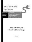
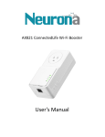
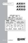
AX501
1 ConnectedLife Adapter
User's
ser's Manual
TABLE OF CONTENT
ORDERING INFORMATION .................................................................................................................................... 2
INCLUDED ITEMS................................................................................................................................................ 3
IMPORTANT SAFETY INSTRUCTIONS ....................................................................................................................... 4
PRODUCT OVERVIEW .......................................................................................................................................... 5
PRODUCT INSTALLATION...................................................................................................................................... 7
Application 1 – local Powerline network among PCs ......................................................................... 7
Application 2 – PC to xDSL router connection .................................................................................... 8
Application 3 – Wireless Access Point range extensions .................................................................... 9
Create private PLC network ............................................................................................................... 10
Remove a device from a logical network Group ............................................................................... 11
Setting different network Group ....................................................................................................... 11
STANDBY MODE ............................................................................................................................................... 12
AC outlets connection ........................................................................................................................ 13
Connection via power strip ................................................................................................................ 15
Electrical interference ........................................................................................................................ 15
Electrical wiring .................................................................................................................................. 15
Special Care for business installation ................................................................................................ 15
SPECIFICATIONS ............................................................................................................................................... 17
FAQ (Frequently Asked Questions) ............................................................................................................ 19
TROUBLE SHOOTING ......................................................................................................................................... 22
ORDERING INFORMATION
Neurona's ConnectedLife family of products have been designed to deliver the highest
quality consumer experience possible. This experience is created by taking a holistic
approach to addressing the demands of an expanding and evolving connected life.
This user manual describes the AX501: ConnectedLife Adaptor with AC-Passthrough
device.
The AX501 ConnectedLife Adapter coverts any power outlet in the home into an Ethernet
port which can be used to connect Smart TVs, Blu-Ray Players, or laptops to the Internet.
The AX501 implements HomePlug Power Line Communications (PLC) technology. This
technology leverages the home's electrical wiring to create a whole home
communications network, which provides the ultimate flexibility when it comes to
installation.
The AX501 ConnectedLife Adapter with AC-Pass-through was designed to prevent the loss
of access to the outlet that it is plugged into, which simplifies the installation for the
consumer. Additionally, the pass-through plug uses advanced noise filtering to ensure
that the device’s performance is not impacted when even the noisiest of devices are
plugged into the AX501's replicated power outlet.
Through the implementation of SmartLink™ technology, the AX501 enhances
performance and home coverage by leveraging all three electrical wires—line, neutral
and ground. This new offering increases overall network performance by up to 50% when
compared to HomePlug solutions that only utilize the line and neutral wires. The result
is a more robust Internet connection everywhere in the home.
The AX501 is compliant with HomePlug AV Specification standard and is equipped with
128-bit AES encryption to keep data secure.
INCLUDED ITEMS
AX501
AX501-B
SmartLink
ConnectedLife Adapter
One AX501
SmartLink
ConnectedLife Adapter Kit
Two AX501s
ETHERNET CABLE
One
Two
DOCUMENTATION
Quick Start Guide
Quick Start Guide
PART NUMBER
DESCRIPTION
DEVICE
NOTICE: This product complies with IC: ICES-006; en conformité avec IC: NMB-006, FCC,
and ETL Safety Standards
IMPORTANT SAFETY INSTRUCTIONS
This product is intended for connection to the AC power line. For installation instructions,
refer to the Installation section. The following precautions should be taken when using
this product:
Please read all instructions before installing and operating.
Please keep all instructions for later reference.
Please follow all warnings and instructions marked.
This product should NOT be installed in any electrical socket with venting holes
facing down towards the floor.
Unplug the Powerline device from the wall outlet before cleaning. Use a dry cloth for
cleaning. DO NOT use liquid cleaners or aerosol cleaners.
DO NOT operate this product near water.
This product should never be placed near or over a radiator or heat register.
This product relies on the building’s electrical installation for short-circuit (over
current) protection.
DO NOT allow anything to rest on the product interconnect plug.
DO NOT place this product in a location where people may step on the cords.
Because this product sends data over the power line, we recommend that you plug
this product directly into a power outlet. Do not plug the device into a UPS or power
strip with surge protection. The product has its own power filter for protection
against surges.
Only a qualified technician should service this product. Opening or removing covers
may result in exposure to dangerous voltage points or other risks.
Unplug the product from the wall outlet and refer the product to qualified service
personnel for the following conditions:
When the interconnect cords are damaged or frayed.
If liquid has been spilled into the product.
If the product has been exposed to rain or water.
If the product does not operate normally when the operating instructions are
followed.
If the product exhibits a distinct change in performance.
PRODUCT OVERVIEW
Product View
AC Pass through
Socket
A
B
C
D
Ethernet Port
E
Button/LED Descriptions
Item name
A
POWER LED
B
Ethernet
Link/Activity LED
Description
ON:: Power on and ready.
BLINKING:
1. (blink at slower rate)
ra means Standby mode, or
2. During Group pairing procedure.. In this procedure, the device joining
or being joined into same logical network will blink for two minutes,
minutes
until the procedure
pr
succeeds or is canceled.. To enter or cancel Group
pairing procedure,
procedure just press the GROUP button 2~3 sec.
OFF:: Power off.
ON:: Ethernet Link Detected.
BLINKING Ethernet traffic detected.
BLINKING:
OFF:: No Ethernet Link detected.
ON:: Powerline Link detected but no powerline traffic.
traff
C
PLC Link/Activity
LED
BLINKING:
BLINKING
1. Fast blinking (0.06 s ON/ 0.06 s OFF): Powerline data rate higher than
60Mbps.
2. Normal blinking (0.2 s ON/ 0.2 s OFF) Powerline data rate between
10Mbps to 60Mbps.
60Mbps
3. Slow blinking (1 s ON1/ 1 s OFF): Powerline data rate slower than
10Mbps.
OFF:: Powerline Link not detected (either other devices in same network is
too far to communicate or it is alone in its logical network).
D
GROUP Button
E
RESET Button
Press 10 seconds: Clear the current and randomly generate a new network
group name.
Press 2 to 3 seconds: This will enter Group pairing procedure. In this
procedure, the device starts joining into a logical network of other device
or announcing its network group name for other devices to join. This
maximum two-minute procedure automatically ends when it succeeds or is
manually stopped. Pressing this button for 2 to 3 seconds will manually
stop the procedure.
Press the button when the device is powered on (not standby) to recover
all Factory default settings (including PLC network group name).
Every new PLC devices’ factory default PLC network group name is
HomePlugAV. During trouble shooting powerline network communication
and network group assignment, doing this to every PLC device will force
every device return to default network group, thus ensure their mutual
communicability.
PRODUCT INSTALLATION
This Powerline device is virtually an Ethernet cable replacement and an Ethernet hub
replacement. Two ConnectedLife Adapter devices replace an Ethernet cable to connect
any PC to another PC, a PC to a DSL/cable router, or a wireless AP to a DSL device. Many
of these devices can be connected together to form a mesh communication. For example,
three computers can connect to a DSL/cable router for Internet access via four Powerline
devices, so each computer connects to one Powerline device while the DSL/cable router
connects to a fourth Powerline device. Here are some installations examples:
Application 1 – local Powerline network among PCs
Use the included Powerline devices for connecting computers in different rooms or floors
at home!
Quick Installation:
Connect the AX501 device to a PC, as shown in Room A of the following picture. The AC
to DC electric adapter cord of desktop PC can be plugged into the pass-through AC socket
of this device.
Create a ConnectedLife network by using another Neurona device in the other room (for
example, Room B). This way, desktop PC at Room A can communicate with Notebook PC
at Room B for sharing files.
Room B
Room A
Homeplug
PLC AV
device
This
device
AC
power
cord
Ethernet
Ethernet
Application 2 – PC to xDSL router connection
Use the included Powerline devices for connecting multiple PC or Ethernet devices to an
xDSL router in any other room!
Quick Installation:
Follow the similar procedure as in Application 1, except, instead of connecting to a
notebook PC, please connect to a DSL or cable modem like in Room B. This way, Desk-top
PC at room A will be able to surf internet via the xDSL modem of Room B.
Room B
Room A
This
device
AC
power
cord
Ethernet
Homeplug
PLC AV
device
Cable/
DSL
modem
Ethernet
Note: Under good power line signal conditions, Room A and Room B can be many rooms
away from each other without communication issues. (See the FAQ section)
Application 3 – Wireless Access Point range extensions
Sometimes, a PC using wireless LAN on one floor of a concrete house cannot access the
wireless AP router installed on different floors. The Powerline Ethernet devices will solve
this problem!
Quick Installation:
Connect the included Powerline device to a wireless Access Point (AP) like picture shown
in Room A. Plug AC to DC electric adapter of the Access Point onto the pass-through AC
socket of this device. If users purchase the dual or combo package, connect another
included Powerline device with a broadband DSL modem like in Room B. If users buy a
single device package, please connect to the modem using other HomePlug AV PLC
device in Room B.
Room A
This
device
AC
power
cord
Ethernet
Room B
Homeplug
AV PLC
device
Room C
Cable/ DSL
modem
Wi-Fi AP
Ethernet
Create private PLC network
Each Powerline device has predefined attributes, such as a DAK (device password) and
Powerline network name. Multiple Powerline devices with the same network names can
communicate to one another, thus belonging to the same PLC network group. Devices
with different network names won’t communicate. The maximum number of devices in a
PLC network group is defined in the SPECIFICATIONS section of this manual.
Any Homeplug-AV-compliant new PLC device, including this device, has its factory default
network name of HomePlugAV, and can communicate with other brands of
Homeplug-AV-compliant devices. Pushing the GROUP button of the device will change its
network name. This way, users can create private or multiple private PLC network groups
in one minute without involving complicated PC software, thus protecting their data that
has been transmitted over the Powerline. Pressing the RESET button of a power-active
device will reset the network name back to its factory default.
By pushing GROUP button for more than 10 seconds, a random network name (different
from HomePlugAV) will be generated. This device can then ask other devices to join its
PLC network to form a private network group. Any other device which joins the private
PLC network group will need to follow steps below.
To enable Powerline device B join Powerline device A’s logical network, follow these
three steps: (NOTE: it is more convenient to bring devices, which are to be configured
into same logical network group, side by side during this procedure. After the network
group is set, the devices can be deployed anywhere within the home).
Step 1. Clear the logical network group of device B by pressing the GROUP button for
more than 10 seconds until all LED lights simultaneously turn off and on one
time. At this moment, its network group name has been changed to a random
name and ready to be assigned another network name. Now, this device also
can be used as a seed device so other PLC devices can join to form a private
network group. Any other device that will join this device’s network group will
also need to go through Step 1.
Steps to join device B to device A’s logical network:
Step 2. Press the GROUP Button of device A for 2 to 3 sec (make sure POWER LED
starts blinking). This forces device A into a maximum two-minute Group pairing
procedure to start broadcasting its network name and wait for another device
to join its network group. This procedure can be manually stopped by
pressing the GROUP button 2 to 3 sec.
Step 3. Less than two minutes after the above step, press the GROUP Button of
device B for 2 to 3 sec (after push, make sure POWER LED starts blinking) to
end the Group pairing procedure. After ~8-10 seconds, the LED light will stop
blinking if device B successfully joined to Device A’s network group, also
signifying that the Group pairing procedure is completed. Thus, device B will
connect to device A and begin transmitting data between the two devices.
This way, Powerline device B joins the same logical network as device A. Users can join
device C to device A’s logical network with same procedure. Thus, both device C and
device B join device A’s logical network. After this procedure, device A, B, and C should
be in the same logical network group. Users can assign as many Powerline devices into
the logical same network group according to the maximum number allowed, which can
be found in the SPECIFICATION section.
Removing a device from a logical network group
If device A and device B are in the same logical network group, and the user wants to
remove device A, follow the procedure in Step 1 by pressing device A’s GROUP button for
10 seconds. After this procedure, device A will no longer be able to communicate with
device B. Similarly, if a user wants to remove a device from a logical network group
containing 3 or more devices, just operate the GROUP button of this device as in Step 1.
Setting a different network group
To remove device B from the logical network of device A, follow Step 1. This way, a
random network name is generated that differs from device A’s network name. By adding
other devices to device B’s network group or to device A’s network group using same
procedures as Step 2 and 3, users can form two groups of logical network.
STANDBY MODE
Standby mode enables the PLC device to save on power consumption. The device will
automatically enter standby mode if no Ethernet cable is connected, or if the PC
connecting this device enters standby, hibernation, or is powered-off after two minutes.
During standby, only POWER LED blinks at slower rate. To exit standby, insert the Ethernet
cable to the device or resume PC back to running.
Note:
Some computers support a “Wake up LAN” function, in which case, the PLC device will not
enter standby mode.
ENHANCE PLC PERFORMANCE DURING INSTALLATION
This Powerline device sends data to and from the devices over the existing electrical
wiring in your home, and may be affected by factors such as electrical noise or a home's
wiring length. Keep the following in mind when placing this Powerline device at home.
AC outlets connection
Avoid connecting this device to an uninterruptible power supply (UPS) or backup power
supply device. For best results, we recommend connecting the adaptors directly to a wall
outlet. Avoid connecting high power-consumption appliances to the same wall outlet.
Plug these power consuming devices into a noise filtering power strip to prevent
interference with the Powerline device. See the following illustration figure:
For optimum performance, the following connection is recommended. Note: devices that
are connected without a noise filter power strip will still function.
The following connections are NOT recommended, although current PLC technology will
overcome most noise interference from electronic devices’ AC adapters or chargers.
Connection via power strip
If you must connect this device to a power strip, please keep the following in mind:
• Make sure the power strip does not have a noise filter or surge protector, as
these features may impair communication signaling of the Powerline device sent
over the electric wiring, resulting in degraded distance capabilities.
• Use a power strip with an AC cord that is as short as possible.
• Do not connect the adaptor to a power strip that receives power from another
power strip.
Electrical interference
Certain electrical devices emit electrical noise. If this noise is spread over to the electrical
wiring in your home, it may interfere with the performance, speed, and reliability of this
device. For best results, we recommend connecting an electrical noise filter to noise
emitting appliances.
The following appliances are more likely to produce noise:
• Battery chargers (including cell phone chargers)
• Hair dryers
• Power drills
• Halogen lights
• Vacuum cleaners
Additionally, this product may interfere with the following appliance:
• Lights or lamps which have a touch-sensitive on/off feature
Electrical wiring
This device sends data to other devices over the existing electrical wiring in your house. If
two spatially neighboring wall outlets are separated by a great distance of electrical wire
routing, these devices may not communicate as well with each other. For more
information, refer to the TROUBLESHOOTING section.
Special Care for business installation
We DO NOT recommend these Powerline devices for business environments due to
several uncertainties which may degrade Powerline performance or block its operation.
This device has NO GUARANTEE to operate in a business environment such as offices or
factories. However, many businesses will find it to be an inexpensive solution to
implement networking with no costly changes to wiring infrastructure.
The distance between two Powerline devices is limited by the noise in the electrical
wiring in that business environment. Interference may be intermittent; for example,
noise may be highest at one time of day or one day of the week. Normally, a business
environment covers a wider area than the recommended home application. Electric
wiring in a business environment may require more than one power meter system, can
result in communication difficulties between Powerline devices.
SPECIFICATIONS
Items
Description
ID
PLC Standard
IEEE 1901 / HomePlug
Home
AV
PHY Rate
500 Mbps over Powerline and 10/100 Mbps over Ethernet
Model
500Mbps SmartLink Powerline Ethernet Bridge with AC-Pass through
PHY: Up to 500 Mbps
Data Transfer Rate
UDP: Up to 98 Mbps
TCP: Up to 94 Mbps
95% Coverage (UDP)
50 Mbps
Dimension
(L× W×H)
93 × 56 × 40
0 mm (plug not included)
Frequency Band
2 MHz to 30
0 MHz,
Super band: 30
0 MHz to 68 MHz.
Power Input
100 ~ 240 VAC 50/60Hz
Power consumption
Pass-through AC
socket types
Full load: (110 VAC) < 3.8 Watts; (220 VAC) < 4.5Watts; (240 VAC) < 5.0
5 Watts
Standby mode: < 0.5W
0.5 @ (110, 220, 240 VAC);
Type B, E, F
Pass -through socket
2M~68MHz : -30dB
30dB at least。
least
AC noise filter
Pass -through socket
16 - 20A
Max. load
Max device weight
on pass-thru socket
165 g
Ethernet port
1X
X
LEDs
(1) Power (green),
(2) Ethernet Link/Activity (green),
10/100 Fast Ethernet
(3) Powerline Activity (green)
Distance
AC Wire: up to 300 meters
Access Methods
Priority-based
based CSMA/CA channel access schemes
Applications
*Extend Broadband access to whole house by AC wire
*Extend wireless network coverage
*IP set-top box
*IP TV
*VOIP phone
*High definition video distribution
*Single IP appliances
QoS
Integrated quality of service
Modulation
OFDM 4096/1024/256/64/16/8 - QAM, QPSK, BPSK and ROBO Modulation
Schemes
LAN Standards
IEEE 802.3, IEEE 802.3U
Max. dev in a
network Group
8(active)/16(total)
PC side Operating
System
OS independent
Encryption
128-bit AES
Other FW features
* Dynamic channel adaptation and channel estimation
* Advanced Turbo Code Forward Error Correction
* Supports IGMP managed multicast Sessions
Temperature
0~40 Degrees C (Operating); -20~60 Degrees C (Storage)
Relative Humidity
Regulation*
10~85% Non-Condensing (Operating)
5~90% Non-Condensing (Storage)
FCC, CE EMC, CE-CB, RoHS, WEEE, ETL
FAQ (Frequently Asked Questions)
1. What is the distance this device can transmit?
ANS: Powerline technology provides reliable coverage over considerable distances in a
home. However, outside noise from your home electrical appliances may be a
limiting factor for the transmission distance. Thus, if many devices are
simultaneously running, the user may get less or more coverage. Please check on
the “maximum distances under good AC wire conditions” in the SPECIFICATIONS
section.
2. What is the throughput?
ANS: The device’s throughput depends largely on several factors: (1) the distance
between devices, (2) interference by other appliances, (3) the number of the same
Powerline devices that share common electric wiring, and (4) the application packet
type – TCP or UDP. TCP applications will be slower than UDP applications. Longer
distance, larger interference, or more Powerline devices will reduce the data
throughput. The maximum throughput between two devices for TCP and UDP are
specified in the SPECIFICATIONS section.
3.
Do I have to rewire my home’s electric outlets or install special filters to use this
device?
ANS: If your wiring is modern, there is no need to rewire outlets or to install special filters.
Powerline uses existing electrical wiring to network computers in different rooms so
that they can share files, printers, and Internet connections. This Powerline product
particularly uses existing electrical sockets (outlets).
4. What type of AC outlet can I use to plug in this device?
ANS: This power line product works with AC 100V to 240V with 2-prong or 3-prong
electrical outlets, depending on whether the plug is 2-prong or 3-prong type.
5. Can this powerline device work with circuit breakers?
ANS: In many countries Powerline signals will not communicate between different
phases. Please have an installer or local expert check your home’s electric wiring
before installation.
6. Is it secure to send private data over this power line device?
ANS: It is secure because the technology supports special data encryption. Please refer
to the SPECIFICATIONS section for the type encryption algorithm used with this device.
7.
How can I connect multiple devices together?
ANS: multiple devices can be connected together if they are in same logical network
group. Use the GROUP button to set the group of this device. By default, newly
shipped devices in a dual or combo package are automatically in same group.
8. How many devices can be assigned into a single group?
ANS: Please see the SPECIFICATIONS section for maximum number of devices that can be
assigned to a single logical network group. There can be multiple groups in same
electric wiring environment.
9. Does any device in a group communicate to any other device in a group?
ANS: Yes. For example, four Powerline devices, A, B, C and D form a logical network group
in which B, C, and D all can communicate with A. if A links to a PC, then B, C, and D
all can share files of the PC. If A links to an xDSL broadband router, then B, C, and D
can surf the internet via the DSL router.
10. Why is a password necessary (called DAK, located at the bottom of the device)?
ANS: The password protects the device from being configured by unauthorized people.
PLC configuration software is available with the older version of Homeplug AV PLC
devices, which don’t have a hardware group button. Since this device comes with a
hardware group button, PLC configuration software is not needed for creating a
logical private network group. The device password is also called DAK, which is
found in the label sticker on the backside of the PLC devices.
11. What standard does this device use?
ANS: This device uses the PLC Standard. Powerline devices from multiple manufacturers
using this same PLC standard are able to communicate with each other. Please see
the SPECIFICATIONS section for the exact PLC standard used in this device.
12. How many devices can I install in my home?
ANS: Multiple devices can be used in a single power-wiring network. However, the more
devices that share the bandwidth, the greater the chance becomes for unintended
performance degradation.
13. Can I install this device in a business environment?
ANS: Powerline devices are not recommended to be used in business environments;
however, the system may function when the placement of two of Powerline devices
are in close proximity to each other. The chance for function is also much greater
without extra electrical noise that is generated by neighboring electrical devices in
the office or factories.
14. Can this SmartLink PLC device communicate with any other PLC devices purchased
in the market?
ANS: PLC devices using a different PLC standard (protocol) may have issues
communicating with each other across electrical wire - line and neutral - although
they all can co-exist with the same electric wires. Check the following table below
for capability of communication between different PLC standards. To understand
what type of PLC standard this device use, please check it in the SPECIFICATIONS
section. Moreover, this SmartLink PLC device can communicate with other SmartLink
PLC devices by transferring data across all three electrical wires—line, neutral and
ground.
Capability of
HomePlug
HomePlug
HomePlug AV
HomePlug AV/
communication
1.0
turbo
200 Mbps
IEEE 1901
between PLC
UPA
HD-PLC
- 500 Mbps
standard
HomePlug 1.0
OK
OK
NO
NO
NO
NO
HomePlug turbo
OK
OK
NO
NO
NO
NO
NO
NO
OK
OK
NO
NO
NO
NO
OK
OK
NO
NO
UPA
NO
NO
NO
NO
OK
NO
HD-PLC
NO
NO
NO
NO
NO
OK
HomePlug AV
200 Mbps
HomePlug AV/
IEEE 1901
-500 Mbps
TROUBLE SHOOTING
New devices are shipped with the same logical PLC network group assignment and
should be mutually communicable at first deployment. If two PLC devices do not
communicate either due to the erasing of the PLC network group during product
shipping, handling, or users deploying, please follow these steps:
Press the RESET button of the powered-on (not entering standby) PLC device with a
needle pin. For safety reasons, do not use a metal pin. This will return the PLC device
into its factory default network group (HomePlugAV). If successful, all LED lights will
turn off and on one time.
Repeat the step above on all PLC devices to ensure they return to the same default
network group. This ensures devices of same network group won’t have any further
communication problems. You can now create a private network group on these
devices when needed.
If the devices still do not communicate, the electric wiring may be causing the
problem. Examples of potential problems are:
– Old fuse boxes.
– Old wiring that does not meet modern wiring building codes.
Make sure the devices are functioning well by plugging these units into nearby
electrical outlets in the same room or into the same power strip with noise filtering.
If these two devices can communicate, go to the Long Distance Debugging Steps
section. If these two devices still cannot communicate, continue to check the
following:
o Check that the Ethernet cables are securely plugged in.
o Check the power supply.
o Check that LED lights are properly lit, blinking, or turned off.
o Uninstall and reinstall the device.
o Conduct a "ping" test to see whether your device is connected to the network.
o Gradually increase the distance between Powerline units. Your testing will
determine whether the distances you can achieve.
Long distance debugging steps:
Gradually increase the distance between the two Powerline devices. Some nearby
outlets may be harder for the devices to communicate than the farer outlets. It all
depends on electrical wiring topologies. Try it with different outlets on different wall
or different rooms.
Swap devices to isolate the problem to a particular Powerline unit.
If there are problem areas, have a qualified electrician review the building’s electrical
plans, assessing the noise conditions for each phase of the powerline.
Pay special attention to the electrical noise generated by the following devices:
–
–
–
–
–
–
Air conditioning
Florescent lights, particularly industrial grade lights
Refrigerators
Surge protectors and other line filters and conditioning
Blowers
Large electrical motors
Note
1)
2)
3)
This Powerline device is not designed for business use. Consult a professional
electrician to evaluate your electricity's noise in your building and to suggest remedies.
If you've moved a Powerline device or disconnected the cables, your PLC devices at the
other end of the powerline network may need up to 5 minutes to start transmitting
connecting information in the same AC wire loop.
Use all the same Powerline models for best connectivity. Also, software for one model
may not work for another model. In particular, remote and advanced features may not
work between Powerline device manufacturers.