1
US008645581B2
(12) Ulllted States Patent
(10) Patent N0.:
Goto et a].
(54)
(45) Date of Patent:
TERMINAL DEVICE
.
~
.
-
CN
2783391
Y
5/2006
JP
2002366268 A
ShImada, Chiba (JP); Yuklhlto Hara,
JP
2003228544 A
8/2003
IchikaWa (JP)
JP
2006244091 A
9/2006
JP
2007-004251
(73) Assignee: Buffalo Inc. (JP)
Notice:
Feb. 4, 2014
FOREIGN PATENT DOCUMENTS
(75) Inventors. Satoru Goto,~Ich1kaWa (JP), :Iunpel
(*)
US 8,645,581 B2
12/2002
1/2007
OTHER PUBLICATIONS
Subject to any disclaimer, the term of this
European Search Repon, EP 09012999, dated Mar, 4, 2010,
patent is extended or adjusted under 35
Chinese Of?ce Action for CN 2009101799788 dated Jul. 15, 2011.
U_S_C_ 154(1)) by 0 days_
Japanese Of?ce Action forApplication No. 2008-269202 datedAug.
7, 2012.
_
European Of?ce Action from Application No. EP 09012990 dated
(21) Appl. No.. 12/587,998
Ju1‘9, 2013‘
_
“umount(8)iLinux man page.” [online]. Jul. 2007. [Retrieved Jul. 9,
(22) Flledi
Oct- 15, 2009
2013] <http://linux.die.net/man/8/umount>.
European Of?ce Action from Application No. EP 090129990 dated
(65)
Prior Publication Data
Oct 24, 2013
Facilis Technology Inc. “TerraBlock User Manual Version 2.0.” Jun.
US 2010/0100644 A1
(30)
(
15, 2006. Retrieved from the Internet: <http://cvp.com/pdf/facilisi
TerraBiockGuide2.0.pdf>, 47 pages.
Foreign Application Priority Data
Oct. 17, 2008
51
Apr. 22, 2010
(Continued)
(JP) ............................... .. 2008-269202
I t Cl
)
n '
(74) Attorney, Agent, or Firm * Lerner, David, Littenberg,
'
G06F 3/00
(52) US. Cl.
(58)
KrumholZ & Mentlik, LLP
(2006.01)
(57)
56
ABSTRACT
UISPC ......... ...... ........................................ .. 710/5
Field of Classi?cation Search
A terminal device including a plurality of logical ports as
rt f
-d1 - 1
tth 1 - 1 n 1 -
USPC ............................................................ .. 710/5
p0 S or provl mg oglca Connec Ions’
See application ?le for complete search history.
(
Primary Examiner i Chun_Kuan Lee
R f
)
e erences
e oglca p0 S Ogl
cally connecting external devices to the terminal device, the
terminal device comprising: a receiver con?gured to receive
an execution instruction for an unmount process Which is a
. .
.
.
.
process of transition from an activated state in Which the
C't d
l 6
us PATENT DOCUMENTS
logical connections are activated to a deactivated state in
Which the logical connections are deactivated; and a control
6,792,558 B2 *
9/2004 Kuwako et a1. ............... .. 714/13
ler con?gured to control the logical ports, Wherein the con
6371252 B1
3/2005 C1111? _
troller deactivates the logical connections corresponding to
6’990’545 B2 *
V2006 Anmllh et a1‘ """"""" " 710602
the lo ical
7,565,473 B2 *
7/2009 Tabira et a1. ................ .. 710/302
2004/0215865 A1
2006/0140179 A1
10/2004 Arimilli et al.
6/2006 Campini et al.
2006/0252184 A1
11/2006 Tabira et al.
g
orts in res onse to the execution instruction for
P
’
P
the unmount Process
14 Claims, 4 Drawing Sheets
DETECT THAT REMOVAL
BUTTON IS PRESSED
RECENE EXECUTION
INSTRUCTION FOR
UNMOUNT PROC E55
UNMOUNT NOTIFICATION
UNMOUNT PROC ESS
ANNUNCIATE THAT
EXECUTION OF UNMOUNT
PROCESS IS COMPLETED
US 8,645,581 B2
Page 2
(56)
References Cited
OTHER PUBLICATIONS
Feb. I, 2002, Retrieved from the Internet: <httpJ/tascam.com/con
tent/doWnloads/products/305/mxfmanualfupdateBfl l.pdf>, 60
pages.
TASCAM Teac Professional Division. “MX-2424 24-Bit 24
Track Hard Disk Recorder.” TASCAM Teac Professional Division.
* Cited by examiner
US. Patent
Feb. 4, 2014
Sheet 1 of4
US 8,645,581 B2
FIG. 1
EXTERNAL DEVICE
TERMINAL DEVICE @100
up
/\/11 0
120
[J
CONTROLLER
RECEIvER
Z
140
I
ANNUNClATOR’\/150
gswml
8
130
US. Patent
Feb. 4, 2014
Sheet 2 0f 4
US 8,645,581 B2
FIG. 2
N112
\
LOGICAL
____
'____
EALYE'Z
LLE’J-‘ LL32) LLPEJ /\/112b
3
PHYSICAL
.---'---. LAYER
> 110
lL__liP___g
AV112a
USB PORT
’\J111
/\/201
200
Z
202
Z
203
US. Patent
Feb. 4, 2014
Sheet 3 of4
US 8,645,581 B2
FIG. 3
|/Fk110
IIF110
1
l/F110
A
120
2
CONTROLLER
1
LOGICAL PORT
STATE DETECTOR
PHYSICAL PORT
STATE DETECTOR
Z
2
121
122
123w PROCESSOR
ANNUNCIATOR 150
RECENER 14o
US. Patent
Feb. 4, 2014
US 8,645,581 B2
Sheet 4 0f 4
FIG. 4
(
START
)
DETECT THAT REMOVAL
BUTTON IS PRESSED
“31 0
I
RECEIVE EXECUTION
INSTRUCTION FOR
UNMOUNT PROCESS
N820
I
UNMOUNT NOTIFICATION
$30
I
UNMOUNT PROCESS
~$40
ANNUNCIATE THAT
EXECUTION OF UNMOUNT ~S50
PROCESS IS COMPLETED
S60
IS EXTERNAL
DEVICE REMOVED?
MOUNT PROCESS
END
US 8,645,581 B2
1
2
TERMINAL DEVICE
connections, the logical ports logically connecting external
CROSS REFERENCE TO RELATED
APPLICATION
ing: a receiver con?gured to receive an execution instruction
devices to the terminal device, the terminal device compris
for an unmount process Which is a process of transition from
an activated state in Which the logical connections are acti
vated to a deactivated state in Which the logical connections
are deactivated; and a controller con?gured to control the
The present application claims priority from Japanese
Patent Application No. 2008-269202 ?led in the Japanese
logical ports, Wherein the controller deactivates the logical
connections corresponding to the logical ports, in response to
Patent Of?ce on Oct. 17, 2008, the entire content of Which is
incorporated herein by reference.
the execution instruction for the unmount process.
According to the ?rst aspect of the present invention, the
BACKGROUND OF THE INVENTION
receiver receives the execution instruction for the unmount
process, and the controller deactivates the logical connections
corresponding to the logical ports, in response to the execu
1. Field of the Invention
The present invention relates to a terminal device including
tion instruction for the unmount process. For this reason, the
unmount process can be easily performed even for an external
multiple logical ports as ports for providing logical connec
tions to logically connect external devices to the terminal
device.
device having no removal button. In addition, according to the
?rst aspect of the present invention, the controller deactivates
the logical connections corresponding to the respective mul
2. Description of the Related Art
Heretofore, there has been knoWn an external device con
nectable to a terminal device, such as a PC, through an inter
face, such as a USB. The terminal device and the external
device are connected to each other by a physical connection to
connect the devices physically and a logical connection to
connect the devices logically. The physical connection means
that the terminal device and the external device are connected
physically by a cable. The logical connection means that the
terminal device and the external device are connected logi
20
tiple logical ports. For this reason, When a certain one of the
multiple external devices is to be removed from the terminal
device, there is no need to select a logical connection to be
deactivated. Any of the external devices can be thus removed
Without using a GUI. Thus, the unmount process for the
25
external devices can be easily executed even in a case Where
a device having no GUI is used as the terminal device. There
fore, the ?rst aspect of the present invention makes it possible
cally through recognition of the external device by the termi
nal device.
Here, a state in Which the logical connection betWeen the
terminal device and the external device is activated is referred
30
to suf?ciently facilitate the unmount process.
A second aspect of the present invention is according to the
?rst aspect of the present invention and is summariZed in that
the controller deactivates the logical connections correspond
ing to the logical ports in response to the execution instruction
to as an “activated state.” On the other hand, a state in Which
the logical connection betWeen the terminal device and the
for the unmount process, and maintains the deactivate state of
external device is deactivated is referred to as a “deactivated
the logical connections until a predetermined condition is
satis?ed.
A third aspect of the present invention is according to the
second aspect of the present invention and is summariZed in
that the predetermined condition is physical removal of any of
the external devices.
A fourth aspect of the present invention is according to the
second aspect of the present invention and is summariZed in
state.” In addition, a process of transition from the deactivated
35
state to the activated state is referred to as a “mount process.”
On the other hand, a process of transition from the activated
state to the deactivated state is referred to as an “unmount
process.”
In general, the terminal device, such as a PC, includes a
graphical user interface (GUI) Which uses images shoWn on a
40
that the receiver receives an execution instruction for a mount
process Which is a process of transition from the deactivated
display. The unmount process described above is performed
by using the GUI.
In addition, as a technique of facilitating the unmount
process, there has been knoWn a technique of providing an
45
external device With a removal button With Which an instruc
tion to execute the unmount process is issued to the terminal
device through the external device (see Japanese Patent
Application Publication No. 2007-4251, for example).
Meanwhile, if an external device having no removal button
is connected to the terminal device, the unmount process still
50
A sixth aspect of the present invention is according to the
?rst aspect of the present invention and is summariZed in that
If consideration is given to a situation Where an external
device having no removal button is connected to a terminal
55
tates the unmount process.
SUMMARY OF THE INVENTION
The present invention, therefore, has been made in vieW of
60
the above problem, and an object thereof is to provide a
terminal device capable of suf?ciently facilitating an
unmount process.
The present invention has the folloWing aspects to solve the
problems described above. First of all, a ?rst aspect of the
present invention is summariZed as a terminal device includ
ing a plurality of logical ports as ports for providing logical
A ?fth aspect of the present invention is according to the
second aspect of the present invention and is summariZed in
that the predetermined condition is an elapse of a predeter
mined period of time after a receipt of the execution instruc
tion for the unmount process.
needs to be performed by using the GUI.
device, there has yet to be a technique that suf?ciently facili
state to the activated state, and the predetermined condition is
that the execution instruction for the mount process is
received.
65
the terminal device further comprising an annunciator con
?gured to annunciate that execution of the unmount process is
completed, When the transition from the activated state to the
deactivated state is completed.
A seventh aspect of the present invention is according to
the ?rst aspect of the present invention and is summariZed in
that the terminal device further comprising a press part con
?gured to be pressed by a user, Wherein the receiver receives
the execution instruction for the unmount process, by press of
the press part.
A eighth aspect of the present invention is according to the
seventh aspect of the present invention and is summariZed in
that the receiver receives an execution instruction for a mount
process Which is a process of transition from the deactivated
US 8,645,581 B2
4
3
state to the activated state, the receiver manages the number of
As shoWn in FIG. 1, the terminal device 100 includes an
pressing actions in each of Which the press part is pressed
once, and When the press part is pressed, the receiver deter
troller 120, a removal button 130 (press part), a receiver 140,
interface 110 (hereinafter, referred to as an I/F 110), a con
and an annunciator 150.
The I/F 110 is a hardWare interface to connect external
mines Whether the receiver has received the execution
instruction for the unmount process or the execution instruc
tion for the mount process, on the basis of Whether the man
aged number of pressing actions is an odd number or an even
devices (unillustrated) to the terminal device 100. The I/F 110
number.
A ninth aspect of the present invention is according to the
?rst aspect of the present invention and is summarized in that,
at a time of executing the unmount process, the controller
physical port is a port used for providing a physical connec
tion Which alloWs the terminal device 100 and the external
devices to be connected physically. The logical ports are ports
used for providing logical connections Which alloW the ter
minal device 100 and the external devices to be connected
includes one physical port and multiple logical ports. The
deactivates all the logical connections formed through the
logically. As the I/F 110, a USB or the like can be used for
logical ports.
example, but the I/F 110 is not limited to it. A con?guration of
the I/ F 110 as Well as the physical connection and the logical
connections Will be described later in detail.
The present invention makes it possible to provide a termi
nal device capable of su?iciently facilitating the unmount
process.
The controller 120 controls the multiple logical ports. A
speci?c con?guration of the controller 120 Will be described
BRIEF DESCRIPTION OF THE DRAWINGS
later in detail.
20
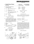
FIG. 1 is a block diagram shoWing a terminal device 100
according to a ?rst embodiment of the present invention.
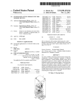
FIG. 2 is a diagram shoWing a con?guration of an interface
110 and a protocol stack related to an operation of the I/ F 110.
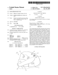
FIG. 3 is a block diagram shoWing a controller 120.
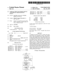
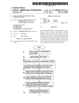
FIG. 4 is a ?owchart shoWing an operation of the terminal
device 100 according to the ?rst embodiment of the present
invention.
DESCRIPTION OF THE EMBODIMENTS
user of the terminal device 100.
The receiver 140 receives an execution instruction for an
unmount process When the removal button 130 is pressed.
25
30
The unmount process is a process of transition from an acti
vated state in Which the logical connections are activated, to a
deactivated state in Which the logical connections are deacti
vated.
Speci?cally, the receiver 140 is connected to the controller
120 and the removal button 130. The receiver 140 monitors
Whether or not the removal button is pressed. Upon detection
that the removal button 130 is pressed, the receiver 140 deter
Next, embodiments of a terminal device according to the
present invention Will be described With reference to the
draWings. Note that throughout the draWings, the same or
similar components are denoted by the same or similar refer
The removal button 130 is provided on an outer surface of
the terminal device 1 00, and is con?gured to be pressed by the
mines that the execution instruction for the unmount process
is received. Upon receipt of the execution instruction for the
35
unmount process, the receiver 140 transmits an unmount
ence numerals. It is to be noted, hoWever, that the draWings
noti?cation indicating receipt of the execution instruction for
are only schematic and that dimensional ratios and the like are
the unmount process, to the controller 120.
When the transition from the activated state to the deacti
different from the actual ones. Thus, speci?c dimensions and
the like should be determined by taking into account the
folloWing descriptions. Moreover, it is needless to say that
40
dimensional relationships and proportions may be different
vated state is completed, the annunciator 150 noti?es that
execution of the unmount process is completed. Speci?cally,
the annunciator 150 is connected to the controller 120 and
acquires a transition completion noti?cation indicating that
betWeen the draWings in some parts.
the transition from the activated state to the deactivated state
First Embodiment
45
?es that the execution of the unmount process is completed.
HereinbeloW, a terminal device according to a ?rst embodi
ment of the present invention Will be described With reference
to the draWings. Speci?cally, the descriptions Will be given
for (l) a con?guration of the terminal device, (2) an operation
of the terminal device, (3) advantageous effects, (4) Modi?
cation l, and (5) Modi?cation 2.
An LED, a speaker, a LCD, or the like can be used as the
annunciator 150, so that the completion of the execution of
the unmount process can be noti?ed of by illuminating or
50
(l) Con?guration of Terminal Device
(1.1) Schematic Con?guration of Terminal Device
55
CPU to execute processing of the I/F 110, the controller 120,
the receiver 140, and the annunciator 150. A recording
medium, such as a RAM, a ROM, a hard disk, a ?exible disk,
a compact disk, an IC chip, a cassette tape, or the like, can be
used as the program holder.
tion Will be described With reference to FIG. 1. FIG. 1 is a
block diagram shoWing a terminal device 100 according to
60
speci?c con?guration of the terminal device 100 is omitted in
(1.2) Con?guration of I/F 110 and Physical Connection and
Logical Connection
Next, a con?guration of the I/F 110 as Well as the physical
connection and the logical connections Will be described With
reference to FIG. 2. FIG. 2 is a diagram shoWing a con?gu
FIG. 1.
The terminal device 100 of the present invention includes
multiple logical ports (Which Will be described later). As the
terminal device 100, a netWork attached storage (NAS) or the
like can be used, but the terminal device 100 is not limited to
it. A PC may be used as the terminal device 100 instead.
?ashing the light, making a sound, displaying a message, or
the like.
Incidentally, although not illustrated herein, a program
holder may be provided Which holds programs to cause a
First of all, a schematic con?guration of the terminal
device according to the ?rst embodiment of the present inven
the ?rst embodiment. It should be noted that illustration of a
is completed, from the controller 120. Upon acquisition of the
transition completion noti?cation, the annunciator 150 noti
ration of the I/F 110 and a protocol stack related to an opera
65
tion of the I/F 110. Here, in FIG. 2, the description Will be
given for a case Where a USB is used as the I/F 110. FIG. 2
also shoWs a case Where an external device group 200 includ
US 8,645,581 B2
5
6
ing multiple external devices is connected to the UP 110. USB
is neWly created betWeen the terminal device 100 and the neW
external device. The logical layer 1121) maintains its non
recognition state until acquiring an activation instruction to
devices, such as a USB storage, a USB printer, and a USB
connected UPS, as Well as a USB hub Which connects the
activate the multiple logical connections.
The logical layer 1121) creates the logical port LP for each
multiple USB devices and the terminal device 100 can be used
as the external devices.
of the external devices physically connected to the terminal
device 100, When acquiring the activation instruction to acti
As shoWn in FIG. 2, the UP 110 includes a USB port 111.
In addition, the UP 110 operates in accordance With a protocol
stack 112 shoWn in FIG. 2. The protocol stack 112 includes a
physical layer 112a and a logical layer 1121).
vate the multiple logical connections, from the controller 120.
Accordingly, the logical layer 1121) activates the logical con
The USB port 111 is a terminal Which mechanically con
nects the terminal device 100 and the external devices.
nections betWeen the terminal device 100 and all the external
devices physically connected to the terminal device 100. In
The physical layer 112a electrically connects the terminal
device 100 and the external devices. Speci?cally, the physical
layer 112a manages a physical port PP for establishing an
electrical communication path betWeen the terminal device
addition, the logical layer 1121) cancels the non-recognition
state When acquiring the activation instruction.
(1.3) Con?guration of Controller 120
Next, a con?guration of the controller 120 Will be
described With reference to FIG. 3. FIG. 3 is a block diagram
100 and each of the external devices.
shoWing the controller 120.
In the physical layer 112a, one physical port PP is created
As shoWn in FIG. 3, the controller 120 includes a logical
port state detector 121, a physical port state detector 122, and
for one USB port 111. For example, in a case Where a USB
hub 201 is connected to the USB port 111 and Where USB
devices 202, 203 are connected to doWnstream ports of the
USB hub 201 as shoWn in FIG. 2, the physical layer 112a
20 a processor 123.
The logical port state detector 121 detects the states of the
multiple logical ports. Speci?cally, the logical port state
establishes electrical communication paths respectively to
the USB hub 201 and the USB devices 202, 203 through one
detector 121 detects Whether or not logical ports are created in
physical port PP.
the logical layer 1121) of the UP 110. Accordingly, the logical
Provided With the mechanical connection to the USB port
25
port state detector 121 detects transition of the state of each of
1 1 1 and the electrical connection through the physical port PP
the logical connections formed respectively through the logi
as described above, the external devices are physically con
nected to the terminal device 100.
cal ports, from the activated state to the deactivated state or
from the deactivated state to the activated state.
The logical layer 1121) logically connects the terminal
device 100 and the external devices. Speci?cally, the logical
The physical port state detector 122 detects the state of the
30
physical port. Speci?cally, the physical port state detector
layer 1121) manages multiple logical ports LP for establishing
122 detects When an electrical connection through the physi
a logical communication path between the terminal device
cal port is neWly formed or is disconnected. Accordingly, the
100 and each of the external devices physically connected to
the terminal device 100. Provided With the logical connec
physical port state detector 122 detects When an external
tions through the corresponding logical ports LP, the external
35
device is neWly connected to the physical port or physically
removed from the physical port.
The processor 123 is connected to the logical port state
detector 121 and the physical port state detector 122. The
processor 123 executes (a) the unmount process, (b) the
mount process, and (c) a transition completion noti?cation
devices are logically connected to the terminal device 100.
In the logical layer 112b, one logical port LP is created for
each of the external devices, Which are physically connected
to the terminal device 100 through the one physical port PP. In
other Words, one or more logical ports LP are created for one 40 process.
physical port PP. For example, as shoWn in FIG. 2, logical
ports LP1, LP2, LP3 are respectively created for the USB hub
201 and the USB devices 202, 203 in the logical layer 1121).
(a) Unmount Process
The logical layer 1121) creates the logical port LP by giving
a descriptor to the external device physically connected to the
terminal device 1 00. In a case Where multiple external devices
are physically connected to the terminal device 100, the logi
45
cal layer 1121) gives different descriptors to the multiple
external devices. When a USB is used as the UP 110, the
logical layer 1121) can use up to 127 descriptors for one
50
physical port PP. In other Words, the logical layer 1121) is
capable of managing 127 logical ports LP for one physical
port PP.
In this event, the deactivation instruction transmitted by the
processor 123 instructs deactivation of all the logical connec
tions formed respectively through the multiple logical ports
55
provided in the UP 110. In other Words, the processor 123
deactivates the logical connections respectively correspond
state and the deactivated state, on each of the logical connec
tions, Which are formed betWeen the terminal device 100 and
the external devices.
ing to the multiple logical ports, in response to the execution
instruction for the unmount process.
After executing the unmount process, the processor 123
The logical layer 1121) deletes all the logical ports LP When
acquiring a deactivation instruction to deactivate the multiple
logical connections, from the controller 120 . Accordingly, the
receiver 140. Speci?cally, When acquiring the unmount noti
?cation from the receiver 140, the processor 123 transmits the
deactivation instruction to deactivate the logical connections,
to the UP 110, thereby to execute the unmount process.
According to an instruction from the controller 120, the
logical layer 112!) performs sWitching betWeen the activated
As described above, the unmount process is a process of
transition from the activated state in Which the logical con
nections are activated, to the deactivated state in Which the
logical connections are deactivated.
The processor 123 executes the unmount process upon
acquisition of the unmount noti?cation transmitted from the
60
maintains the multiple logical connections in the deactivated
state until a predetermined condition is satis?ed. In other
Words, the processor 123 does not execute the mount process
logical layer 1121) deactivates all the logical connections. In
addition, the logical layer 1121) transitions to a non-recogni
until the predetermined condition is satis?ed. The predeter
tion state When acquiring the deactivation instruction. The
mined condition Will be described later in detail.
non-recognition state refers to a state in Which, even When a 65
neW external device is connected to the terminal device 100,
The processor 123 may determine Whether or not to
execute the unmount process, on the basis of a detection result
no logical port LP is neWly created, i.e., no logical connection
from the logical port state detector 121. For example, the
US 8,645,581 B2
7
8
processor 123 may determine not to transmit the deactivation
tion noti?cation, the annunciator 150 annunciates that execu
tion of the unmount process is completed.
In Step S60, the controller 120 detects whether or not any
of the external devices are physically removed. The controller
instruction, when acquiring the unmount noti?cation while
the multiple logical connections are in the deactivated state.
(b) Mount Process
120 proceeds to Step 70 upon detection of physical removal
The mount process is a process of transition from the
deactivated state in which the logical connections are deacti
vated, to the activated state in which the logical connections
are activated. In the ?rst embodiment of the present invention,
the predetermined condition for the processor 123 to execute
the unmount process is physical removal of any of the exter
nal devices.
of any of the external devices. If not, the controller 120
repeats the process of Step 60 until it detects removal of any
of the external devices from the physical port.
In Step S70, the controller 120 executes the mount process
and then terminates the processing. Consequently, the mul
tiple logical connections for the remaining external devices
transition to the activated state.
The processor 123 executes the mount process in accor
dance with a detection result from the physical port state
(3) Advantageous Effects
detector 122. Speci?cally, when the physical port state detec
tor 122 detects physical removal of any of the external
devices, the processor 123 transmits the activation instruction
to activate the logical connections for the remaining external
devices, to the UP 110, thereby to execute the mount process.
In this event, the activation instruction transmitted by the
processor 123 instructs activation of the logical connections
between the terminal device 100 and all the remaining exter
nal devices physically connected to the terminal device 100
20
instruction for the unmount process, the receiver 140 trans
mits the unmount noti?cation to the controller 120. Upon
acquisition of the unmount noti?cation, the controller 120
through the physical port. In other words, upon physical
removal of the external device, the processor 123 activates the
25
logical connections respectively corresponding to the
remaining multiple logical ports.
sition completion noti?cation indicating that the transition
from the activated state to the deactivated state is completed,
to the annunciator 150. Speci?cally, the processor 123 trans
mits the transition completion noti?cation to the annunciator
150 when the logical port state detector 121 detects state
transition of the logical connections from the activated state
executes the unmount process. With such a con?guration, the
unmount process can be easily performed even for an external
device having no removal button.
In addition, in the terminal device 100 according to the ?rst
(c) Transition Completion Noti?cation Process
The transition completion noti?cation process is a process
of notifying the annunciator 150 of the state transition of the
multiple logical connections from the activated state to the
deactivated state.
In accordance with the detection result from the logical
port state detector 121, the processor 123 transmits the tran
In the terminal device 100 according to the ?rst embodi
ment of the present invention, the receiver 140 receives the
execution instruction for the unmount process when the
removal button 130 provided on the outer surface of the
terminal device 100 is pressed. When receiving the execution
30
embodiment of the present invention, the controller 120
instructs deactivation of all the logical connections at the time
of executing the unmount process.
It is to be noted that the following problem would arise if
the removal button, which is provided to the external device in
the conventional technique, were simply provided to the ter
35
minal device 100. Speci?cally, in a case of the terminal device
1 00 including multiple logical ports, when the removal button
is pressed in order to remove any of the multiple external
devices connected to the terminal device 100, it is necessary
to select which logical connection to deactivate, by selecting
40
to the deactivated state.
(2) Operation of Terminal Device
a logical port through which the external device to be
removed is logically connected. In this case, a GUI is required
to select the logical connection to be deactivated.
However, a device having no GUI, such as an NAS, is also
used as the terminal device. Therefore, to remove an external
Next, an operation of the terminal device 100 according to
the ?rst embodiment of the present invention will be
45
device connected to the terminal device having no GUI, it is
necessary to select a logical connection corresponding to the
external device to be removed, by means of a remote opera
tion performed by a different terminal device having a GUI.
Otherwise, the terminal device having no GUI needs to be
50
powered off.
described with reference to FIG. 4. FIG. 4 is a ?owchart
showing the operation of the terminal device 100 according to
the ?rst embodiment. Note that in the ?owchart shown in FIG.
4, at least one external device is assumed to be connected to
the terminal device 100.
As shown in FIG. 4, in Step S10, the removal button 130 is
pressed by the user of the terminal device 100.
In Step S20, the receiver 140 detects that the removal
button 130 is pressed, and thus determines that an execution
instruction for the unmount process is received.
In Step S30, the receiver 140 transmits an unmount noti?
In contrast, in the terminal device 100 according to the ?rst
embodiment of the present invention, the controller 120 deac
tivates all the logical connections formed through the respec
tive multiple logical ports, when executing the unmount pro
55
a logical connection to be deactivated, even when multiple
cation indicating receipt of the execution instruction for the
external devices are connected to the terminal device 100.
unmount process, to the controller 120. The controller 120
acquires the unmount noti?cation from the receiver 140.
In Step S40, the controller 120 executes the unmount pro
60
tion to the deactivated state.
deactivated state. Upon acquisition of the transition comple
Any of the external devices can be thus removed without
using a GUI. Accordingly, the unmount process for the exter
nal devices can be performed easily even in a case where a
device having no GUI, such as an NAS, is used as the terminal
cess. Consequently, the multiple logical connections transi
In Step S50, the controller 120 transmits a transition
completion noti?cation to the annunciator 150 when detect
ing the state transition of all the logical connections to the
cess in response to the execution instruction for the unmount
process. With such a con?guration, there is no need to select
65
device 100.
As has been described thus far, with the terminal device
100 according to the ?rst embodiment of the present inven
tion, it is possible to suf?ciently facilitate the unmount pro
cess.
US 8,645,581 B2
10
In addition, in the terminal device 100 according to the ?rst
embodiment of the present invention, the controller 120 does
nal device group 200. The present invention, hoWever, is not
limited to this case. For example, the predetermined condition
may be an elapse of a predetermined period of time after the
receiver 140 receives the execution instruction for the
not execute the unmount process until the predetermined
condition is satis?ed, and executes the unmount process When
the predetermined condition is satis?ed, more speci?cally,
When detecting physical removal of any of the external
unmount process.
devices. Such a con?guration alloWs continuous use of the
external devices other than the external device to be removed,
Without having to physically remove and re-insert the exter
nal devices.
Moreover, in the terminal device 100 according to the ?rst
embodiment of the present invention, the annunciator 150
annunciates that the execution of the unmount process is
completed, When the transition from the activated state to the
deactivated state is completed. Such a con?guration alloWs
the user of the terminal device 100 to knoW the timing for
timer (unillustrated) Which measures a predetermined period
of time. The receiver 140 activates the timer When detecting
that the removal button 130 is pressed. Upon expiry of the
timer, the receiver 140 transmits a timer expiry noti?cation to
the controller 120.
The processor 123 of the controller 120 according to Modi
?cation 2 executes the mount process upon acquisition of the
timer expiry noti?cation. As in the case of the above-de
scribed ?rst embodiment, the processor 123 of Modi?cation 2
transmits the activation instruction, to the UP 110, the activa
physically removing the external device.
tion instruction to execute the mount process, namely, to
The receiver 140 according to Modi?cation 2 includes a
activate the logical connections betWeen the terminal device
100 and all the external devices physically connected to the
(4) Modi?cation l
20
HereinbeloW, the terminal device 100 according to Modi
?cation l of the ?rst embodiment of the present invention Will
be described. In the above-described ?rst embodiment of the
present invention, the description is given for the case Where
the predetermined condition for the processor 123 of the
Other Embodiments
25
controller 120 to execute the mount process is the physical
removal of any of the external devices constituting the exter
nal device group 200. The present invention, hoWever, is not
limited to this case. For example, the predetermined condition
may be that the receiver 140 receives an execution instruction
for the mount process.
Hereinabove, the content of the present invention has been
disclosed using an embodiment of the present invention.
HoWever, it should not be understood that any of the descrip
tions and the draWings Which form part of this disclosure
limits the present invention. From the disclosure, various
alternative embodiments, applications, and operation tech
30
niques should be apparent to those skilled in the art.
For example, in the above-described ?rst embodiment, the
description is given for the case Where the terminal device 1 00
is provided With the removal button 130 and the unmount
process is executed When the receiver 140 detects that the
35
removal button 130 is pressed. The present invention, hoW
The receiver 140 according to Modi?cation l manages the
number of times the removal button 130 is pressed since the
terminal device 100 is poWered on. Based on the number of
times of the pressing action, the receiver 140 determines
terminal device 100 through the physical port.
Whether it has received the execution instruction for the
ever, is not limited to this case. For example, the receiver 140
mount process or the execution instruction for the unmount
process.
may be provided With a communication interface and acquire
a signal indicating the execution instruction for the unmount
When detecting that the removal button 13 0 is pressed, and
the number of times of the pressing action is an odd number,
the receiver 140 determines that it has received the execution
instruction for the unmount process. On the other hand, When
the number of times of the pressing action is an even number,
the receiver 140 determines that it has received the execution
instruction for the mount process. The receiver 140 then
transmits the mount noti?cation indicating receipt of the
execution instruction for the mount process, to the controller
120.
The processor 123 of the controller 120 according to Modi
?cation l executes the mount process upon acquisition of the
mount noti?cation. As in the case of the above-described ?rst
embodiment, the processor 123 of Modi?cation l transmits
the activation instruction, to the UP 110, the activation
instruction to execute the mount process, namely, activate the
logical connections betWeen the terminal device 100 and all
the external devices physically connected to the terminal
process, from a remote controller outside the terminal device
40
100 through the communication interface.
In addition, in the above-described ?rst embodiment, the
description is given for the case Where the terminal device 1 00
is provided With one USB port 111, but the present invention
45
provided With multiple USB ports 111.
Moreover, in the above-described ?rst embodiment, the
is not limited to this case. The terminal device 100 may be
description is given for the case Where the terminal device 1 00
includes the annunciator 150, but the present invention is not
limited to this case. The terminal device 100 may not include
50
?rst embodiment, the description is given for the case Where,
based on the number of times a single removal button 130 is
pressed, the receiver 140 determines Whether it has received
55
device 100 through the physical port.
(5) Modi?cation 2
60
HereinbeloW, the terminal device 100 according to Modi
?cation 2 of the ?rst embodiment of the present invention Will
be described. In the above-described ?rst embodiment of the
present invention, the description is given for the case Where
the predetermined condition for the processor 123 of the
controller 120 to execute the mount process is the physical
removal of any of the external devices constituting the exter
the annunciator 150.
Furthermore, in the above-described Modi?cation l of the
the execution instruction for the mount process or the execu
tion instruction for the unmount process. The present inven
tion, hoWever, is not limited to this case. For example, the
terminal device 1 00 may be provided With tWo buttons. In this
case, the receiver 140 determines that it has received the
execution instruction for the unmount process, When detect
ing that one of the tWo buttons is pressed, Whereas the receiver
140 determines that it has received the execution instruction
for the mount process, When detecting that the other one of the
buttons is pressed.
65
As described above, the present invention includes various
embodiments and the like Which are not described herein, as
a matter of course. Hence, the technical scope of the present
US 8,645,581 B2
11
12
invention is to be de?ned solely by the features of the present
invention according to the scope of claims appropriate from
the above descriptions.
What is claimed is:
1. A terminal device comprising:
a plurality of logical ports as ports for providing logical
unmount process or the execution instruction for the
mount process, on the basis of Whether the managed
number of pressing actions is an odd number or an even
number.
8. A terminal device comprising:
a plurality of logical ports as ports for providing logical
connections, the logical ports logically connecting
connections, the logical ports logically connecting
external devices to the terminal device, each external
device is logically connected only to the terminal device
external devices to the terminal device, and each exter
nal device is logically connected only to the terminal
by the logical ports;
device by the logical ports;
a receiver con?gured to receive an execution instruction for
an unmount process Which is a process of transition from
an activated state in Which the logical connections are
activated to a deactivated state in Which the logical con
nections are deactivated; and
a receiver con?gured to receive an execution instruction for
an unmount process Which is a process of transition from
an activated state in Which the logical connections are
activated to a deactivated state in Which the logical con
nections are deactivated;
a controller con?gured to control the logical ports, Wherein
the controller deactivates the logical connections corre
sponding to all the logical ports in response to the execu
a controller con?gured to control the logical ports, Wherein
the controller deactivates the logical connections corre
sponding to all the logical ports in response to the execu
tion instruction for the unmount process Without the
tion instruction for the unmount process Without the
external devices communicating With each other; and
20
a press part con?gured to be pressed by a user, Wherein the
pressed part is on the terminal device and the receiver
receives the execution instruction for the unmount pro
cess after the press part is pressed.
2. The terminal device according to claim 1, Wherein the
25
controller deactivates the logical connections corresponding
to all the logical ports in response to the execution instruction
for the unmount process, and maintains the deactivate state of
the logical connections until a predetermined condition is
satis?ed.
3. The terminal device according to claim 2, Wherein the
receiver receives an execution instruction for a mount process
to transition from the deactivated state to the activated state,
and the predetermined condition is that the execution instruc
30
external devices.
4. The terminal device according to claim 2, Wherein the
the activated state, and
the predetermined condition is that the execution instruc
tion for the mount process is received.
5. The terminal device according to claim 2, Wherein the
predetermined condition is an elapse of a predetermined
period of time after a receipt of the execution instruction for
the unmount process.
35
40
the unmount process.
6. The terminal device according to claim 1, further com
prising an annunciator con?gured to annunciate that execu
tion of the unmount process is completed, When the transition
from the activated state to the deactivated state is completed.
7. The terminal device according to claim 1, Wherein
of Which the press part is pressed once, and When the
press part is pressed, the receiver determines Whether the
receiver has received the execution instruction for the
12. The terminal device according to claim 8, further com
prising an annunciator con?gured to annunciate that execu
tion of the unmount process is completed, When the transition
from the activated state to the deactivated state is completed.
13. The terminal device according to claim 8, further com
prising a press part con?gured to be pressed by a user,
Wherein the receiver receives the execution instruction for the
unmount process When the press part is pressed.
14. The terminal device according to claim 8, Wherein
the receiver receives an execution instruction for a mount
45
process Which is a process of transition from the deac
tivated state to the activated state,
the receiver manages a number of pressing actions in each
of Which a press part is pressed once, and When the press
part is pressed, the receiver determines Whether the
the receiver receives an execution instruction for a mount
process Which is a process of transition from the deac
tivated state to the activated state,
the receiver manages a number of pressing actions in each
tion for the mount process is received.
11. The terminal device according to claim 8, Wherein the
predetermined condition is an elapse of a predetermined
period of time after a receipt of the execution instruction for
predetermined condition is physical removal of any of the
receiver receives an execution instruction for a mount process
Which is a process of transition from the deactivated state to
external device communicating With each other, and
maintains the deactivate state of the logical connections
until a predetermined condition is satis?ed.
9. The terminal device according to claim 8, Wherein the
predetermined condition is physical removal of any of the
external devices.
10. The terminal device according to claim 8, Wherein the
50
receiver has received the execution instruction for the
unmount process or the execution instruction for the
mount process, on the basis of Whether the managed
number of pressing actions is an odd number or an even
number.