1
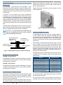
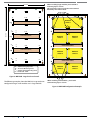
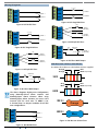
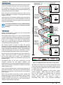
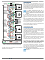
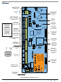
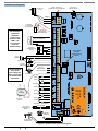
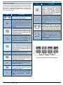
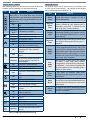
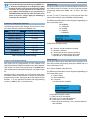
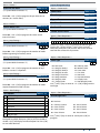
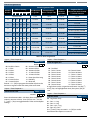
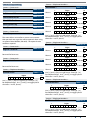
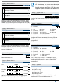
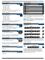
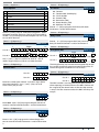
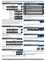
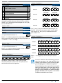
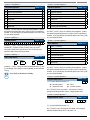
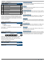
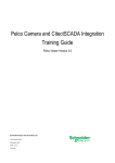
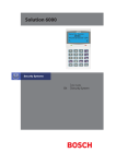
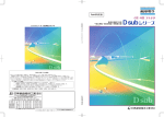
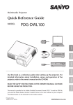
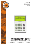
Solution 144 Quick Start Guide
Con n ec t ing Power To The Pane l
Transformer Output
(Red Wires)
For normal operation, the panel requires both AC and DC
power sources. The AC source can be provided either by an
external adapter or by an internal transformer depending
on the model and country of sale.
When connecting using the AC adapter, feed the cable in
to the enclosure and terminate the wires on the removable
terminal block supplied before connection it to the PCB.
D
FUSE
8AG - 250V
250mA MAX
NEUTRAL
N
L
L
ACTIVE
F U SED
A
B
A
C
The panel is supplied with a set of battey leads to suit the
chosen enclosure. Connect the RED battery lead to the
battery (+) terminal and the BLACK battery lead to the
battery (-) terminal on the PCB.
A
B
C
D
Once terminated onto the PCB connect the other end of
the leads to the battery paying attention to the polarity.
On models with an internal transformer, a permanent
connection shall be made to the mains supply. See
Figure 8. This must be completed by a suitably qualified
electrician according to the applicable wiring standards
and regulations.
TRANSFORMER
220 - 240V A.C.
50-60Hz 150mA
EARTH
Co n n e c t ing The B atte r y
AC M a in s Tra nsfor m e r O pt ion
A
Transformer
Input
(Blue Wires)
N
If using a 3 wire adaptor, then the earth wire should also
be terminated onto the terminal block. Always check the
orientation of the terminal block with the PCB markings
before connecting it to the PCB.
A
Wiring must be carried out by
a licensed electrician following
applicable wiring standards
=
=
=
=
PCB Mounting Clip Holes
Enclosure Mounting Holes
Fused Terminal Block
Transformer
Figure 8: Internal Transformer Connection Diagram
Pan e l L ED I n di cator s
The control panel PCB has two LED indicators (Dialler and
Status LED’s) which display the following information.
Next connect the transformer output wires (red) to the
removable terminal block supplied and then connect it
to the PCB. Always check the orientation of the terminal
block with the PCB markings before connecting.
Condition
Off
On
Flashing
For permanently connected equipment, a readily
accessable disconnect device shall be installed in a
Note location near to the equipment.
i
Meaning
Offline
On Line (Dialling/Answered)
Incoming Call
Table 2: Dialler Indicator LED
Condition
Off
On
Flash Once Every 2 Seconds
Flash Fast
Meaning
Error
Error
OK
AC or Battery Trouble
Table 3: Status Indicator LED
During factory defaulting the Status and Dialler LED
indicators will flash alternatively for approximately
Note 15 seconds.
i
8
Bosch Security Systems 10/12 BLCC600R