1
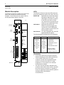
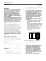
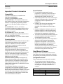
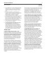
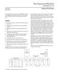
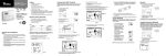
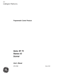
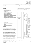
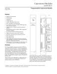
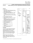
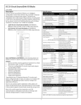
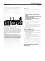
Bus Expansion Modules
1
Remote I/O Scanner
GFK-0539D
August 2006
The IC697 Remote I/O Scanner (IC697BEM733/735)
is an intelligent module that mounts in a remote
IC697 rack, and interfaces IC697 I/O modules to an
IC66* bus.
The Remote I/O Scanner is ideally suited for use in
an IC697 PLC system. However, any type of PLC or
computer capable of controlling an IC66* bus can be
used as the host.
a42453
CPU
Features
▪
Can be located up to 7500 feet (2275 meters)
from controller.
▪
Supports standard IC697 discrete and analog I/O
modules.
▪
Supports PCM, ADS, and analog expander
modules.
▪
Handles up to 128 bytes of inputs and 128 bytes
of outputs per remote drop.
▪
Configurable with programming software or
Hand-held Monitor.
▪
Remote I/O Scanner IC697BEM733/735B or
later supports both CPU and IC66* bus
redundancy.
▪
Each remote drop can include up to eight racks,
with a Remote I/O Scanner located in rack 0.
▪
Up to 30 remote drops can be located on the
same IC66* bus.
BUS
CONTROLLER
HAND-HELD
MONITOR
COMMUNICATIONS
BUS
REMOTE DROP
P
S
S
C
A
N
N
E
R
I/O BLOCKS
Together, a Remote I/O Scanner and the modules it
serves make up a remote drop on the
communications bus. A remote drop can consist of
up to eight racks, linked by Bus Transmitter and Bus
Receiver modules. 9–slot and/or 5–slot IC697 racks
can be used. The maximum distance from the first
rack to the last rack in a remote drop is 50 feet (15
meters).
The Remote I/O Scanner can handle any mix of
discrete and analog inputs and outputs up to a total
of 1024 discrete inputs and 1024 discrete outputs, or
64 analog inputs and 64 analog outputs (regardless
of the number of racks in the remote drop). A remote
drop can include all presently–available IC697
discrete modules, analog modules, and analog
expander modules. Bus Transmitter, Bus Receiver,
PCM, and ADS modules can also be placed in a
remote drop (requires Remote I/O Scanner version
3.5 or later). A remote drop cannot have any I/O
module interrupts, bus controllers, communications
modules, or other modules that depend on COMREQ
instructions for their operations.
Required Equipment
The following additional equipment may be required
to use a Remote I/O Scanner:
▪
▪
At least one IC697 5–slot or 9–slot remote rack
with power supply.
If the parallel version of Logicmaster
programming software will be used, the remote
drop must include a Bus Transmitter Module
(IC697BEM713).
If the remote drop will be part of a multidrop network,
which cannot be guaranteed to be on the same
electrical ground and served by the same phase on
the mains, isolation must be provided separately for
each CPU and Remote I/O Scanner. If isolation is
required, use the RS–422 Isolated Repeater/RS–232
converter (catalog number IC655CCM590), or
equivalent product.
2
Bus Expansion Modules
GFK-0539D
August 2006
Remote I/O Scanner
Module Description
LEDs
The Remote I/O Scanner consists of a single circuit
board, with a hinged door which serves as a
faceplate. The module does not require batteries;
the faceplate battery holder is not used.
The Remote I/O Scanner has three LEDs that show
through the transparent portion at the top of the door.
Module OK
lights when the module has passed
its powerup diagnostic tests. If this
LED flashes, it indicates a problem.
If this LED is off, there is a fatal
error that will cause the Remote I/O
Scanner to go to stop/faulted mode.
I/O Enabled
lights when the Remote I/O
Scanner is receiving output data
from the CPU. If this LED flashes,
either I/O data is forced or there is a
Device Number conflict.
Bus B Active
on a dual (redundant) bus, this LED
lights when Bus B is active.
The following table summarizes the LED indications.
a44761
MODULE OK LED
I/O ENABLED LED
BUS B ACTIVE LED
IC66*
HAND HELD
MONITOR
CONNECTOR
BEM 733
MODULE OK
I/O ENABLED
BUS B ACTIVE
ON = OK,
ACTIVE
MODULE FUNCTION
IC66* BUS
REMOTE I/O
SCANNER
SERIAL
GENIUS
HAND HELD
MONITOR
PORT
RS-422/485
COMPATIBLE
SERIAL
PORT
RS-422/485
COMPATIBLE
IC66*
BUS
TERMINALS
Normal Operation
Blinking
On
Fault detected
On
Blinking
I/O data forced
Alternate
blinking
Alternate
blinking
Fault detected, and I/O
data forced
Synchronous
blinking
Synchronous
blinking
Device Number conflict
On
Off
Outputs not being
updated from CPU
Off
Off
No power or fatal error
SER2
SER1A
SHIELD
IN A
SER2A
SHIELD
OUT A
Connectors
SER1B
SHIELD
IN B
▪
SER2B
SHIELD
OUT B
9–pin male D Connector: the upper connector.
Used for attaching an IC66* Hand–held Monitor.
▪
15–pin female D Connector: the center
connector is an RS–422 compatible RS–485
serial port, for direct connection of a serial
programmer or for connection to a multidrop
communications network.
▪
The IC66* bus terminal strip is attached to the
connector at the bottom of the module. Because
the terminal strip is removable, it is possible to
service or replace the module while the system is
operating without disrupting bus
communications.
D
N
On
SHIELD
OUT
N
A
On
Meaning
SHIELD
IN
E
U
I/O Enabled
SER1
R
D
Module OK
C
Y
MODULE
IC697BEM733
LABEL
44A726758-110R02
BEM 733/735
3
Bus Expansion Modules
Remote I/O Scanner
GFK-0539D
August 2006
between the Bus Transmitter and the Remote I/O
Scanner. Slot 2 is recommended.
Operation
The Remote I/O Scanner scans the I/O modules in
the remote drop in the same manner as a CPU
scans the I/O modules in the PLC. At powerup,
scanning begins immediately unless a fatal
diagnostic error occurs. All I/O in a remote drop,
except those that are forced, default to Off at
powerup. I/O that are forced at powerup start in the
forced state or value.
During operation, the Remote I/O Scanner first scans
the input modules in rack and slot order, storing the
input data in its own %I and %AI memories. Then, it
scans the output modules in rack and slot order,
sending them the most recent output data from its
own %Q and %AQ memories.
▪
In a multiple–rack remote drop, a Bus Receiver
must be located in slot 1 of each expansion rack.
▪
A high–level analog input module and its
associated expander modules must be installed
in the same rack of a remote drop. The high–
level analog input module must be in the lowest
slot position of the group, with the expander
modules to its right.
▪
Empty slots are permitted between modules, with
two exceptions:
1. There can be no empty slots to the left of a
Bus Transmitter, analog, PCM, or ADS
module.
2. If, in the future, modules will be placed in the
empty slots and a Hand–held Monitor will be
used to reconfigure the remote drop, locate
empty slots to the right in the rack.
Otherwise, reconfiguration will change the
I/O references assigned to the boards
already there.
IC66* Communications with the Host
After the Remote I/O Scanner completes a
successful login with the host, it begins data transfer
on the IC66* bus. When the Remote I/O Scanner
receives the bus communications token, it transmits
the most recent input data from the configured
portion of its %I and %AI memories. When the
host’s bus controller has the communications token,
it sends the Remote I/O Scanner new output data
from the host. The Remote I/O Scanner places the
output data into the configured portion of its %Q and
%AQ memories.
REMOTE DROP
P
S
Remote Drop Installation
The Remote I/O Scanner User’s Manual gives
installation procedures for the racks, power supplies,
and modules in a remote drop. Be sure to follow the
grounding procedures carefully.
Module Locations
A remote drop can consist of up to eight IC697 racks,
numbered 0 to 7. Rack numbers are configured by
setting the jumpers located on the rack backplane.
See the User’s Manual for instructions. Before
installing modules in a remote drop, determine where
to place them.
▪
The Remote I/O Scanner must be located in rack
0, slot 1 (remote drop).
▪
A Bus Transmitter can be located in any slot of
rack 0; however, there must be no empty slots
S
C
A
N
N
E
R
I
/
O
I
/
O
I
/
O
I
/
O
a44753
I
/
O
Remote I/O Scanner Installation
▪
▪
Be sure the rack is powered–down.
▪
Align the module’s printed circuit board with the
connector on the rack backplane. Slide it
towards the connector until it begins to seat.
▪
Place one thumb on the left of the top plastic
flange and the other thumb on the left of the
bottom plastic flange. Push the board into the
connector until the top and bottom latches click
onto the rack rails.
▪
Be sure the module has seated properly.
Grasp the module firmly and insert it into the
card guide.
4
Bus Expansion Modules
GFK-0539D
August 2006
▪
Remote I/O Scanner
If the rack is in a high–vibration area, use screws
to secure the module in the rack.
Remote I/O Scanner Removal
▪
▪
Be sure the rack is powered–down.
▪
Squeeze the rack clips on the back of the cover
with your fingers to disengage the clip from the
rack rail and pull the board firmly to remove it
from the backplane connector.
▪
Slide the printed circuit board along the card
guide and remove it from the rack.
Grasp the module firmly at the top and bottom of
the board cover with your thumbs on the front of
the cover and your fingers on the plastic clips on
the back of the cover.
IC66* Bus Connections
For single (non–redundant) bus installations, the
IC66* bus cable is connected to the upper four
terminals of the Remote I/O Scanner (1 – 4 in the
diagram). The lower eight terminals are not
connected.
Remote I/O Scanner to additional devices which are
controlled by its bus switching action, it connects to
the top four terminals (1 – 4); otherwise the top four
terminals are unused.
The maximum exposed length of bare wires should
be two inches. For added protection, each shield
drain wire should be insulated with spaghetti tubing
to prevent the Shield In and Shield Out wires from
touching each other or the signal wires.
On a bus, connect Serial 1 to the Serial 1 terminals
of the previous device and the next device. Connect
Serial 2 to the Serial 2 terminals of the previous
device and the next device. Connect the Remote I/O
Scanner’s Shield In terminal to Shield Out of the
preceding device. Connect Shield Out to Shield In of
the next device. If the Remote I/O Scanner is the
first device on a bus, Shield In can be left
unconnected. If it is the last device on a bus, Shield
Out can be left unconnected. Note that the IC66*
bus connections for a Remote I/O Scanner are not
the same as the connections for an IC697 bus
controller, even though the terminals are physically
identical.
a44890
FOR
SINGLE
BUS
CONNECT
BUS TO
TOP FOUR
TERMINALS
NOT
USED
FOR A
DUAL
BUS
SER
1
1
SER
2
3
SER1A 5
R
E
D
7
U SER2A
N
D
A SER1B 9
N
C
Y
SER2B 11
2
SHIELD
IN
4
SHIELD
OUT
6
SHIELD
IN A
8
SHIELD
OUT A
10
SHIELD
IN B
12
SHIELD
OUT B
IC66*
BUS
REMOTE
I/O SCANNER
CONTROLLER
SER1
CONNECT
BUS
STUB CABLE
HERE
TERMINALS
FOR
BUS A
TERMINALS
FOR
BUS B
For dual (redundant) bus installations, the serial bus
cable from the Bus Controller on bus A connects to
the center four terminals on the terminal strip (5 – 8
in the diagram). The cable from the Bus Controller
on Bus B connects to the lower four terminals (9 –
12). The Remote I/O Scanner contains an integral
bus switching relay; there is no need to attach an
external Bus Switching Module for dual bus
configurations. If there is a bus stub from the
SER2
SHIELD
OUT
a44755
SER1
SHIELD IN
SER2
SHIELD
OUT
SHIELD
IN
IC66* Bus Termination
If the Remote I/O Scanner is at either end of a bus
(electrically), connect the appropriate terminating
resistor across the Serial 1 and Serial 2 terminals.
Impedance for the IC66* bus will be 75, 100, 120, or
150 ohms. Chapter 2 of the I/O System User’s
Manual (for IC660*) lists the correct impedance to
use for each approved type of bus cable.
In a redundant bus application, if either cable of the
dual bus ends at the Remote I/O Scanner, it must
have its own terminating resistor. The upper four
connectors are never terminated in a dual bus
configuration.
5
Bus Expansion Modules
Remote I/O Scanner
GFK-0539D
August 2006
Note
If the Remote I/O Scanner will be powered
up when not connected to a properly–
terminated bus, connect a 75–ohm resistor
across its Serial 1 and Serial 2 terminals to
assure proper powerup.
Serial Port Connections
The Remote I/O Scanner’s serial port can be used
for connection to a multidrop communications
network or for direct connection of a programmer
using serial communications.
Serial Port Termination
If the Remote I/O Scanner will be at the end of a
communications network, or if a programmer will be
connected directly to it through an RS-442/485 cable,
the serial port must be terminated by connecting a
220 ohm resistor across pins 10 and 11 and another
220 ohm resistor across pins 8 and 15. These
connections must be made inside the connector’s D–
shell. At the other end of the cable, terminate the SD
and RTD pins in the same way.
Direct Programmer Connections
If the programmer uses a standared PC serial
communications port, connection must be made via
an intermediate RS422/RS485 to RS232 converter.
If the Remote I/O Scanner serial port is needed for
connection to a multidrop communications network,
an intermediate connector can be used. See the
Remote I/O Scanner User’s Manual for details.
If the programmer is equipped with the parallel
version of Logicmaster programming software and a
Workstation Interface board, connection is made to a
Bus Transmitter module in rack 0.
If the programmer is equipped with the serial version
of Logicmaster programming software and a
Workstation Interface board, connection is made to
the serial port on the Remote I/O Scanner module.
Programmer Grounding
For proper operation, the programmer must have a
ground connection in common with remote drop rack
0. Normally, the common ground connection is
provided by connecting the programmer’s power
cord to the same power source (with the same
ground reference point) as the rack. If a common
ground cannot be established, use the RS–422
Isolated Repeater/RS–232 Converter
IC655CCM590, or an equivalent product to protect
the equipment.
Configuration
A Remote I/O Scanner must be configured to:
▪
▪
▪
Assign its Device Number (serial bus address).
Assign its baud rate.
Specify starting references and lengths for
discrete inputs and outputs, and for analog
inputs and outputs.
▪
Specify the Remote Drop ID.
Configuration can be done with:
▪
Machine Edition Logic Developer PLC
configuration software.
▪
Logicmaster programming software release 3.0
or later. This software provides full configuration
of I/O modules and allows selection of module
options.
▪
An IC66* Hand–held Monitor, version 4.0 or
later. The HHM automatically assigns I/O
references to the modules in the remote drop.
The I/O modules in the remote drop operate in
default mode if a Hand–held Monitor is used to
enter or change configuration. If the remote drop
includes any analog expanders, a Hand–held
Monitor cannot be used for configuration.
IC697 PLC Configuration
If the system host is an IC697 PLC, each Remote I/O
Scanner must be added to the PLC configuration.
With Logicmaster programming software release 3.0
or later, a separate program folder should be created
for each remote drop. The folders should be
organized so that the remote drop folders are located
in the central PLC folder. The Remote I/O Scanner
User’s Manual gives complete configuration
instructions.
6
Bus Expansion Modules
GFK-0539D
August 2006
Important Product Information
Remote I/O Scanner
Open Problems
1.
Compatibility
This Remote I/O Scanner is compatible with:
IC66* Hand–held Monitor:
version 4.0 (IC660HHM501G) or later.
For an IC697 PLC: CPU firmware release 2.0 or
later, Machine Edition Logic Developer programming
software, or Logicmaster programming software
release 3.0 or later, Bus Controller release 3.0 or
later.
For an IC600 PLC: CPU rev. 105 or later,
Logicmaster programming software release 4.02 or
later, Bus Controllers (IC660CBB902 or 903) must
be version 1.7 or later.
For an IC655 PLC: CPU rev. 4.0 or later,
Logicmaster programming software release 2.01 or
later, any version Bus Controller.
For a Host Computer: any version PCIM or QBIM.
Operating Notes
Analog Reference Address Limits: Do not use %AI or
%AQ references greater than 64 for analog I/O
modules in a Remote I/O Scanner hardware
configuration. Programming software does not
always enforce these limits.
Rack Sizes: Autoconfiguring a Remote I/O Scanner
with a Hand-held Monitor always generates a
configuration for a nine-slot rack, regardless of the
actual rack size. If a five-slot rack is being used, the
rack size can be entered using the programmer
software. The Hand-held Monitor will subsequently
display the correct rack type.
Serial Bus Address Conflict: If the Remote I/O
Scanner detects an SBA conflict, the SBA conflict
must be resolved. The Remote I/O Scanner logs a
fault, which prevents scanning. This fault must be
cleared with the programmer or HHM before normal
operation can begin.
Force /Release: Normally, an output that is
configured for Hold Last State operation will retain
the last value it received from the Bus Controller
before losing communications. However, if an output
is forced, and communications are lost before the
force is released, the output retains is forced state
until communications are restored.
2.
3.
4.
5.
6.
If a configuration downloaded from the
programmer to a Remote I/O Scanner has an
incorrect or missing module in the rack, the
appropriate fault contacts will not be set.
If the Hand-held Monitor is used to autoconfigure
a Remote I/O Scanner with no I/O modules, the
configuration cannot be uploaded to the
programmer.
I/O data in the I/O map, for which there is no
corresponding I/O module configured, is
displayed on an HHM as word values with no
labels.
Repeated configuration changes may alter the
IC600 and IC550 PLC reference assignments.
IC600 and IC550 PLC users should check that
information after changing the configuration.
This version of the Remote I/O Scanner does not
check the backplane rack jumper settings. Be
sure that jumpers are set to zero.
The checksum generated by autoconfiguration is
different from the checksum generated by
programmer configuration. If the PLC has a
programmer configuration for the Remote I/O
Scanner, and the Remote I/O Scanner is
subsequently autoconfigured using the same I/O
and references, it may generate error: “Remote
I/O Scanner config does not match PLC”.
User Manual Changes
In Chapter 4 of the Remote I/O Scanner Module
User’s Manual, the section Configuration Limits will
be replaced by the following text at the next revision:
Configuration Limits
These configuration limits must not be exceeded:
1. The maximum amount of data that may be
exchanged with any drop, including a Remote
I/O Scanner, is 128 bytes of %I plus %AI data
and 128 bytes of %Q plus %AQ data. For
example:
Limits For Typical Combinations of %I and %AI Data
%I
%AI
1024 Points (128 Bytes)
None ( 0 Bytes)
512 Points ( 64 Bytes)
32 Words ( 64 Bytes)
None ( 0 Bytes)
64 Words (128 Bytes)
Bus Expansion Modules
Remote I/O Scanner
2.
Any combination of %I and %AI data that totals
128 bytes or less is valid. Any combination of
%Q and %AQ that totals 128 bytes or less is
valid.
3.
For each I/O module in a remote drop, the
maximum reference address (start address plus
length in points or words) cannot exceed
%I1024, %AI64, %Q1024, or %AQ64.
4.
5.
6.
If the configured size of %AI and/or %AQ data in
the PLC CPU is less than 64 words, then the
size of %AI and/or %AQ data in a remote drop is
limited to the size configured for the CPU.
There must not be too many option modules in
the remote drop. See chapter 1.
The I/O configuration data must not be greater
than 4500 bytes total. This amount of
configuration data will never be reached in a
remote drop where all of the I/O modules are
included in the Remote I/O Scanner’s I/O map.
Turn to appendix B if the remote drop will have
I/O modules configured outside the I/O map.
I/O Map Limits
In Machine Edition Logic Developer ─ PLC
programming software, the Remote I/O Scanner and
its associated rack(s) and I/O modules (the remote
drop) comprise a separate target from the PLC that
controls the Genius bus. The Remote I/O scanner
exists in both targets – as a Genius device in the
PLC target and as a slot 1 controller in the remote
drop target. Each target has its own separate I/O
map for the Remote I/O Scanner.
In the PLC target, the Remote I/O Scanner with its
I/O Map tab occurs in the Genius bus configuration
for the Bus Controller, at the SBA number where the
scanner is configured. The other I/O map occurs in
the Main Rack, Slot 1 configuration for the remote
drop target. If the remote drop target is not linked to
the PLC target, these two I/O maps may be
configured independently with different sets of
reference addresses. The two I/O maps are unlinked
when the value of the Linked Target Name
parameter in the remote drop Properties window is
“<None>”.
7
GFK-0539D
August 2006
The I/O map for the remote drop target must conform
to the I/O reference address limits from item 2 of the
Configuration Limits section. This will occur
automatically if the AutoMap parameter in the I/O
Map tab is “On”. If AutoMap is “Off”, users must
verify that all reference address limits are observed.
If the I/O maps in the remote drop and PLC targets
are linked, then the reference address limits for I/O
modules in the remote drop also apply to the I/O map
for the Remote I/O Scanner in the PLC target.
Accordingly, reference addresses in the PLC for I/O
modules in the remote drop are limited to small
values. These modules should be configured before
any other I/O to assure that their reference
addresses conform to the required limits.
However, if the two targets are not linked, then the
reference address limits for the remote drop do not
apply to the I/O map in the PLC target. The PLC
reference addresses may take any value permitted
by the programming software.
In Logicmaster 90 programming software, the
Remote I/O Scanner has just one I/O map.
Reference addresses in remote drop I/O modules,
the remote drop I/O map, and the PLC configuration
are all linked together. Editing any of these reference
addresses will automatically change the other two.
To assure that reference addresses in the remote
drop meet the limits from item 2 of the Configuration
Limits section, I/O modules in the remote drop
should be configured before any other I/O.
Control and VersaPro programming software do not
support direct configuration of remote drops. Instead,
the Remote I/O Scanner must be configured on its
Genius bus as a Generic I/O Device, and the remote
drop must be configured separately using the HandHeld Monitor or other programming software that
supports remote drops. The Hand-Held Monitor
automatically enforces the I/O reference address
limits from item 2 of the Configuration Limits section.
The I/O map of the Generic I/O Device in the PLC
configuration may have any reference addresses that
are valid for the PLC CPU.
8
Bus Expansion Modules
Remote I/O Scanner
GFK-0539D
August 2006
Specifications
Module Type
LEDs
Size
Ports
Current Required from +5V Bus
Bus Type
Bus Termination
Baud Rate
Maximum Bus Length
Maximum Number of Devices per Bus
Maximum Number of Remote Drops per
Bus
153.6K baud extended
153.6K baud extended
76.8K baud
IC697 Remote I/O Scanner, IC697BEM733/735
Module OK, I/O Enabled, Bus B Active
Occupies single slot in IC697 remote rack
One 15–pin RS–422/485 compatible serial port,
one 9–pin IC66* Hand–held Monitor port.
0.8 amps
Daisy–chained bus cable; single twisted pair plus shield or Twinax. Fiber
optics cable and modems can also be used.
75, 100, 120, or 150 ohm resistor at both ends of electrical bus cable.
Configurable. 153.6 Kbaud standard, 153.6 Kbaud extended, 76.8 Kbaud, or
38.4 Kbaud.
7500 feet (2275 meters) at 38.4 Kbaud, 4500 feet (1365 meters) at 76.8
Kbaud, 3500 feet (1060 meters) at 153.6 Kbaud extended, 2000 feet 605
meters) at 153.6 Kbaud, standard. Maximum length at each baud rate also
depends on cable type. The IC66* I/O System User’s Manual
provides a complete list of cable types, showing corresponding bus lengths
and baud rates.
32 devices at 153.6 Kbaud standard, 153.6 Kbaud extended, or 76.8 Kbaud.
16 devices at 38.4 Kbaud. Includes bus controller and Hand–held Monitor.
Depends on baud rate as follows:
Up to 20 fully–loaded drops, or up to 30 drops if not fully–loaded.
Up to 20 fully–loaded drops, or up to 30 drops if not fully–loaded.
Up to 10 fully–loaded drops, or up to 30 drops if not fully–loaded.
Refer to GFK–0867B, or later for product standards and general specifications. For installations requiring compliance to more
stringent requirements (for example, FCC or European Union Directives), refer to Installation Requirements for Conformance
to Standards.
Note: For Conformal Coat option, or Low Temperature Testing option please consult the factory for price and availability.
For More Information,
Please refer to these related publications:
Remote I/O Scanner Module User’s Manual.
Programmable Controller Installation Manual.
Programming Software User’s Manual.
Programmable Controller Reference Manual.