1
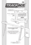
®
TRACKACE LASER WHEEL ALIGNMENT GAUGE USER MANUAL
Laser unit on/off switch
Requires 2 x AAA Batteries
(Not supplied)
TOE IN
TOE OUT
20
20’ 40’ 10 20’ 40’
20 40’ 20’ 1050’40’30’20’10’ 10’ 30’ 50’ 10’ 30’ 50’
50’ 30’ 10’
PLEASE READ ALL THE INSTRUCTIONS BEFORE
COMMENCING WITH YOUR WHEEL ALIGNMENT CHECK
When placing against the wheel, both
legs simply push fit onto the wheel gauge.
Adjust the angle of either leg to level the
gauge with reference to the level bubble.
Patented Product GB2477147
Europe Pending - US Pending
0
SAFETY WARNINGS
Read all these instructions to avoid injury to yourself and others.
Never let anyone use your Trackace without the instruction manual.
Download extra printable manuals at www.trackace.co.uk
The Trackace is intended for use to diagnose vehicle front wheel alignment. It should only
be used as instructed; by a competent person who has fully read and fully understands the
instructions. If you do not understand the instructions do not use the Trackace.
The Trackace should only be used after you have checked all the vehicles wheel mounting
and suspension components are in good working order with reference to the relevant service
and repair manual. Any adjustments to the vehicle must be done by a competent person with
reference to the manufacturer’s recommendations and relevant service and repair manual.
The Trackace uses a visible laser that emits low radiation levels that can be harmful to the
eyes, at less than 1mW momentary accidental eye exposure is considered safe by international
laser standards authorities, but never stare at the beam or allow the beam or reflected beam to
point at a person or animal. Make others in the vicinity aware that you are using a laser and
keep children out of the area. Only turn on the laser when required and turn the laser off as
soon as the check is complete. Never leave the Trackace unattended.
LASER RADIATION
DO NOT STARE INTO BEAM
CLASS 2 LASER PRODUCT
650 nm
<1mW
IEC-EN-60825-1, Ed 2:2007-03
The Trackace should always be stored securely out of reach of children and mentally disabled
adults and always with the batteries removed.
Before inserting batteries, ensure unit is switched off.
Ensure all relevant health and safety regulations for your environment are observed at all times.
The user should not be under the influence of alcohol or drugs. If you use prescription drugs
check with your doctor if it is safe for you to use machinery before use.
In the event of breakage take appropriate safety precautions for handling glass, use appropriate
gloves and eye protection.
The Trackace should only be used on solid level ground, clear of obstructions and vehicle traffic.
Do not use by the roadside or in wet or windy conditions.
Trackace Limited cannot be held responsible for any loss or injury arising from disregard of any
of the safety warnings.
1
Introduction and assembly.
The Trackace provides quick and easy diagnosis of front wheel alignment (Toe angle)
on vehicles with as little as 100mm ground clearance on up to 22” wheels in degrees° and
minutes’, accurate to 0°01’ (0.0166 decimal degrees). 60’ (minutes) = 1° (degree).
Minimal assembly is required. The wheel contact points are provided on the two mounting legs
which simply push fit onto the wheel gauge (see illustrations on front cover).
The Trackace is designed to work on the wheel rims. Read through the checking procedure
including the tips on page 8 to help you use the Trackace properly.
Taking care of your Trackace.
Your Trackace is a diagnostic instrument and should be treated with care.
Keep your Trackace in its original moisture resistant storage box.
Do not store below -5˚C / 23˚F or above 50˚C / 122˚F.
If stored below 5˚C / 41˚F warm at room temperature for 30 minutes before use.
Never leave the legs fitted to the bar or the flex fit may be affected.
Clean your Trackace with a warm damp cloth using a mild detergent.
Clean the mirror with a glass cleaner, following the manufacturer’s instructions.
Always remove the batteries for storage.
Prepare your car for a tracking check.
Follow the vehicle manufacturer’s recommendations for wheel alignment testing
(i.e. check tyre pressures, remove items from car etc).
Select an area of solid level ground. Drive very slowly forward for approximately 2 metres with
the steering in the straight ahead direction. Stop the vehicle as gently as possible, do not allow
the car to roll back, apply the hand brake and turn off the ignition. Never back the vehicle into
position. Gently rock the front of the vehicle up and down to settle the suspension. You are now
ready to perform the front wheel alignment check.
Important.
When performing your tracking check the wheel gauge should lean against the wheel rim, never
lean the gauge on contaminated or damaged parts of the wheel rim or the balancing weights
where fitted. Record your results as + positive toe (for toe in) and – negative toe (for toe out).
2
Stage 1
1a
Laser Unit Placement (view from both front and side)
Use the length of the wheel gauge to place the
laser unit at the correct distance from the right
hand wheel. The capped end should touch the
wheel rim and the mirror surround should
squarely touch the upright front of the laser unit.
Once in position the laser unit should
be just forward of the right hand wheel.
1b
Wheel Gauge Placement (view from both front and side)
RIM
Working from the left hand wheel, attach legs to the wheel gauge to suit the width of the rim.
Lean against the wheel rim at a suitable stable height. Level the gauge by adjusting the angle of
either leg with reference to the level bubble, (see illustration on the front cover).
Check the gauge is contacting with the rim.
3
Stage 1 (continued)
1c
WARNING
To ensure you are not exposed to the
reflected laser beam on the next step,
the mirror should not be left vertical at
this point. The mirror must be angled
so that it reflects towards the ground
as shown in the ticked box.
Check the gauge is still contacting
with the rim and is still level.
1d
Turn the laser unit on and adjust the angle and level of the laser beam until it hits the
centre of the mirror, carefully maintaining the units set distance from the right hand wheel.
1e
Adjust the mirrors vertical angle until the reflected laser beam is level with the scale on the laser unit.
If it hits inside the scale check the gauge is still contacting with the rim and is still level, goto Stage 1f.
If the laser hits outside the scale or misses the laser unit completely see the tip on next page.
4
Tip - Find Mirror Centreline
If at Stage 1e the reflected laser beam hits outside the scale (Fig A) to either side, the
laser dot may disappear when adjusting to zero at Stage 1f, or if it misses the laser unit
completely (Fig B) to either side, it is necessary to move the laser unit to the centreline
of the mirror, this is at the centre of the two beams (dashed line in Fig A & B)
Position a marker (like a coin) at this central position. If the laser beam misses the laser
unit completely adjust the mirror so the reflected laser beam hits the ground to the side
of the laser unit for reference.
A
B
marker
marker
Turn off the laser. Start again from Stage 1a, this time position the laser unit central with
the marker as shown in Fig C, this should ensure the reflected laser beam hits inside the
scale at Stage 1e and does not disappear when adjusting to zero at Stage 1f.
If the vehicle or steering is moved, repeat these steps to find the centreline again.
C
marker
5
Stage 1 (continued)
1f
Fine adjust the angle of the laser unit until the laser dot is centred on the zero line,
carefully maintaining the units set distance from the right hand wheel.
IMPORTANT
Once zeroed, the laser unit must not be
moved again for the remainder of this check.
Note:
The laser is focused to give an easy to
centre larger dot at this stage and a
smaller fine dot at the result stage.
In darker conditions it is normal for dim
patterns to become visible around the
laser dot. Centre on the main dot only.
Adjusting.
Zeroed.
TOE IN
40’ 20’
50’ 30’ 10’
6
TOE OUT
0 20’ 40’50’ 10’20’30’40’50’
40’ 20’
10’ 30’
50’ 30’ 10’
This completes stage 1. The Trackace is now calibrated to the left wheel.
Stage 2
2a
2a
(side view)
Move the wheel gauge to the right hand
wheel rim. Again position the gauge at a
suitable stable height and level with
reference to the level bubble.
2b
Result
TOE OUT
TOE IN
40’ 20
40’ 10 20’30’ 50’
20’ 0 20’
20 40’ 20’10’1050’40’30’ 10’ 10’ 30’ 50’ 10’
50’ 30’
Adjust the mirrors vertical angle until the
reflected laser is level with the scale on the
laser unit. Check the gauge is still contacting
the rim and is still level.
The angular difference between the wheels
is now shown by the laser dot on the scale.
Record your result as + for toe in / - for toe out.
2c
After recording your result, to confirm that the laser unit did not move after step 1f, return the
wheel gauge to the left wheel rim, again at a suitable stable height and level with reference to
the level bubble. Adjust the mirrors vertical angle so that the laser is again level with the scale on the
laser unit. Check the gauge is still contacting the rim and is still level. Check that the laser is still on the
zero line for the left wheel. If not on zero, disregard the result and perform the whole checking
procedure again. If it is still on zero, then you can be confident your result is accurate.
Finally
To compensate for any rim run out (bent wheels) it is necessary to perform a second
tracking check with the wheels rotated 180˚ (half a turn) and compare both results as
instructed in the next box.
7
Rim run out check
On completing one tracking check mark one wheel
at the top centre point, use non damaging chalk,
crayon or sticky tape etc. Move the vehicle forward
until the mark is at the bottom centre point of the
wheel. Re-settle the suspension and perform a
second tracking check. If the two results differ add
them together using the +/- values and divide the
total by 2 to find your average toe angle.
(+ result = toe in) and (- result = toe out)
X
X
Forward direction
TIPS
Tip 1
When adjusting the mirror’s vertical
angle, apply light pressure to the top
of the bar to help the rubber feet grip
the ground for a stable smooth action.
Do not contact damaged parts of the
rim or wheel balancing weights
where fitted.
Tip 2
The Trackace measures up to 2 degrees toe in/out,
any more is excessive toe in/out indicated by which
side of the scale the laser dot is at the result stage.
If the result completely misses the laser unit adjust
the mirror as at Stage 2b so the reflected laser
beam hits the ground in front of the laser unit to see
which side of the scale the laser dot is, indicating
excessive toe in or excessive toe out.
Applicable standards.
EN-60825-1, Ed2:2007-03
2011/65/EU
2004/108/EC
-Safety Of Laser Products
-RoHS Restriction of Hazardous Substances in Electrical and Electronic Equipment
-EMC Elecromagnetic Compatibility Directive
Technical data.
Laser Wavelength
Optical Power
Operating Voltage
Power Supply
Accuracy
Operating Temperature
Storage Temperature
Weight Boxed
Size Boxed
Wheel Range
Vehicle Ground Clearance
650 nm
0.5~0.9 mW
2.7~3.2V DC
2x AAA 1.5V Batteries.
0˚1’ / 0.0166˚ decimal degrees.
5˚C to 40˚c (41˚F to 104˚F)
-5˚C to 50˚C (23˚F to 122˚F)
Approximately 1kg
W 75.5cm x D 18.5cm x H 3.5cm
10” to 22” wheels
Minimum 100mm
Guarantee.
This product is guaranteed against manufacturing defects for a period of twelve months.
This cover does not include accidental breakage, faults arising from use contrary to the instructions,
misuse, abuse or where the product has been subject to an unauthorised repair or modification.
Please retain your proof of purchase and in the unlikely event that the product develops a fault within
the guarantee period that is deemed to be a manufacturing defect, please email your contact details
along with a copy of your proof of purchase to [email protected] so we can arrange a
replacement.
This does not effect your statutory rights.
8
Settings for most vehicles can be downloaded from www.trackace.co.uk/settings
Trackace measures angles in degrees ( ° ) and minutes ( ’ )
60’ minutes = 1° degree (e.g. 1°30’ = 1 ½ degrees)
Converting millimetre values to degrees° minutes’.
If you have inch values see below for conversion to mm’s first.
Wheel Size (inch”)
mm’s
10”
11”
12”
13”
14”
15”
16”
17”
18”
19”
20”
21”
22”
0.1
0.2
0.3
0.4
0.5
0.6
0.7
0.8
0.9
1’
3’
4’
5’
7’
8’
10’
11’
12’
1’
2’
4’
5’
6’
7’
8’
10’
11’
1’
2’
4’
5’
5’
7’
8’
9’
10’
1’
2’
3’
4’
5’
6’
7’
8’
10’
1’
2’
3’
4’
5’
6’
7’
8’
9’
1’
2’
3’
4’
5’
5’
7’
7’
8’
1’
2’
2’
4’
4’
5’
6’
7’
8’
1’
2’
2’
3’
4’
5’
5’
7’
7’
1’
2’
2’
3’
4’
5’
5’
6’
7’
1’
1’
2’
3’
4’
4’
5’
5’
7’
1’
1’
2’
3’
4’
4’
5’
5’
6’
1’
1’
2’
2’
3’
4’
5’
5’
6’
1’
1’
2’
2’
3’
4’
4’
5’
5’
1
2
3
4
5
6
7
8
9
10
11
12
13
14
15
14’
27’
41’
54’
1° 08’
1° 21’
1° 35’
1° 48’
2° 02’
2° 15’
2° 29’
2° 42’
2° 56’
3° 09’
3° 23’
13’
25’
37’
49’
1° 02’
1° 14’
1° 26’
1° 38’
1° 50’
2° 03’
2° 15’
2° 28’
2° 40’
2° 52’
3° 04’
11’
23’
34’
45’
56’
1° 08’
1° 19’
1° 30’
1° 41’
1° 53'
2° 04’
2° 15’
2° 26’
2° 38’
2° 49’
10’
21’
31’
41’
52’
1° 02’
1° 13’
1° 23’
1° 34’
1° 44’
1° 55’
2° 05’
2° 15’
2° 26’
2° 36’
10’
19’
29’
38’
49’
58’
1° 08’
1° 17’
1° 27’
1° 37’
1° 46’
1° 56’
2° 05’
2° 15’
2° 25’
9’
18’
27’
36’
45’
54’
1° 04’
1° 13’
1° 22’
1° 31’
1° 40’
1° 47’
1° 58’
2° 07’
2° 16’
8’
17’
25’
34’
42’
51’
59’
1° 08’
1° 16’
1° 25’
1° 33’
1° 41’
1° 50’
1° 58’
2° 07’
8’
16’
24’
32’
40’
48’
56’
1° 04’
1° 11’
1° 20’
1° 28’
1° 35’
1° 43’
1° 52’
1° 59’
8’
15’
23’
30’
38’
45’
53’
1° 00’
1° 08’
1° 15’
1° 23’
1° 30’
1° 38’
1° 45’
1° 53’
7’
14’
22’
28’
35’
43’
50’
57’
1° 04’
1° 11’
1° 19’
1° 25’
1° 32’
1° 40’
1° 47’
7’
14’
20’
27’
34’
41’
47’
54’
1° 01’
1° 08’
1° 14’
1° 21’
1° 28’
1° 35’
1° 41’
7’
13’
19’
26’
32’
38’
45’
52’
58’
1° 04’
1° 11’
1° 17’
1° 24’
1° 30’
1° 37’
6’
13’
19’
25’
31’
37’
43’
49’
55’
1° 02’
1° 08’
1° 14’
1° 20’
1° 26’
1° 32’
If required simply add the decimal fraction from above to the whole mm from below
(example 5.5 mm on 13 inch wheels would be 52’+5’ = 57’)
Convert inch fractions to mm’s rounded to 1 decimal place using the chart below.
inch
1/64
1/32
3/64
1/16
5/64
3/32
7/64
1/8
9/64
5/32
11/64
mm
0.4
0.8
1.2
1.6
2.0
2.4
2.8
3.2
3.6
4
4.4
inch
3/16
13/64
7/32
15/64
1/4
17/64
9/32
19/64
5/16
21/64
11/32
mm
4.8
5.2
5.6
6
6.4
6.7
7.1
7.5
7.9
8.3
8.7
inch
23/64
3/8
25/64
13/32
27/64
7/16
29/64
15/32
31/64
1/2
33/64
mm
9.1
9.5
9.9
10.3
10.7
11.1
11.5
11.9
12.3
12.7
13.1
inch
17/32
35/64
9/16
37/64
19/32
39/64
5/8
41/64
21/32
43/64
11/16
mm
13.5
13.9
14.3
14.7
15.1
15.5
15.9
16.3
16.7
17.1
17.5
inch
45/64
23/32
47/64
3/4
49/64
25/32
51/64
13/16
53/64
27/32
55/64
mm
17.9
18.3
18.7
19.1
19.4
19.8
20.2
20.6
21.0
21.4
21.8
inch
7/8
57/64
29/32
59/64
15/16
61/64
31/32
63/64
1
mm
22.2
22.6
23.0
23.4
23.8
24.2
24.6
25.0
25.4
To convert decimal inch values to mm’s multiply by 25.4 and round to 1 decimal place.
(e.g. 0.25” x 25.4 = 6.35mm, rounded = 6.4mm ).
Rounding to 1 decimal place, if 2nd decimal place is below 5 then just delete it,
if 2nd decimal place is 5 or above then delete it and add 1 to the first decimal place.
(e.g. 6.34mm becomes 6.3mm but 6.35 becomes 6.4).
9
EC DECLARATION OF CONFORMITY
Trackace Ltd,
declare that the
Trackace Laser Wheel Alignment Gauge
Complies with,
2004/108/EC
-EC Electromagnetic Compatibility Directive
Technical file holder:
Trackace Ltd
Unit G
7 Wykebeck Mount,
Leeds,
LS9 0HN
Name: Terence Grogan
Director
Date: 08/01/11
Waste electrical products should not
be disposed of with normal household
waste. Please recycle where facilities
exist. Check with your Local Authority
or retailer for recycling advice.
www.trackace. co. uk