1
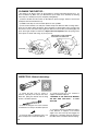
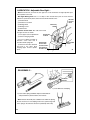
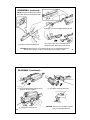
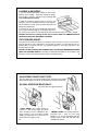
BFI OP. MANUAL
PDF Version
WARNING: BEFORE USING THlS FIREARM,
READ AND FOLLOW THESE INSTRUCTIONS.
If there is anything you do not understand,
get help from someone qualified in the safe handling of firearms.
®
For all
BUSHMASTER
XM15 Models
OPERATING AND SAFETYA1 & A2 Sight Systems
All Rifles & Carbines
INSTRUCTION MANUAL
including V Match
PLEASE PRACTICE SAFE FIREARMS HANDLING!
This instructional manual should always accompany your Bushmaster firearm.
WA RN I N G: IF THIS FIREARM IS CARELESSLY OR IMPROPRERLY HANDLED,
UNINTENTIONAL DISCHARGE COULD RESULT AND COULD CAUSE INJURY,
DEATH, OR DAMAGE TO PROPERTY.
CA U T I ON : CAREFULLY READ THIS INSTRUCTION MANUAL PRIOR TO LOADING
AND FIRING THIS FIREARM. FOLLOW ALL INSTRUCTIONS ON THE PROPER
HANDLING AND SAFE USE OF THIS FIREARM - LIVES MAY DEPEND ON IT! If
unfamiliar with firearms, seek further advice through safe handling courses run by your
local gun clubs, NRA approved instructor, or similar qualified organizations.
CA U T I ON : USE ONLY CLEAN, DRY, HIGH QUALITY COMMERCIALLY
MANUFACTURED AMMUNITION IN GOOD CONDITION which is appropriate to the
.223 Rem. caliber of your firearm. We do not recommend the use of remanufactured or
hand loaded ammunition because it may damage your rifle. Use of improper ammunition
will invalidate your warranty.
WA RN I N G: THIS WEAPON COULD CHAMBER A ROUND if it is dropped or jarred with
a loaded magazine in place - either with the Bolt Carrier Assembly locked to the rear, or in
its forward position.
PLEASE PRACTICE SAFE FIREARMS HANDLING!
FUNDAMENTAL RULES FOR SAFE GUN HANDLING
ALWAYS KEEP THE GUN POINTED IN A SAFE DlRECTlON.
NEVER LOAD THE GUN UNTIL READY TO USE.
KEEP YOUR FINGER OFF THE TRIGGER UNTIL READY TO SHOOT.
WARNING: BEWARE OF DANGEROUS PROCEDURES
• Be sure cam pin is installed in the bolt group. If it isn't, your rifle can still fire and will
explode.
• If you are using a blank firing attachment, never fire anything except blank
rounds (for safety, we recommend the visible military style blank firing attachment).
• If your rifle stops firing with a live round in the chamber of a hot barrel (a misfire),
remove the round fast. However, if you cannot remove it within 10 seconds, remove
magazine and wait 15 minutes with the rifle pointing in a safe direction. This way you
won't get hurt by a possible round “cooking-off” (i.e. the round detonating just from the
heat of the barrel). In any event, keep your face away from the ejection port while
clearing a hot chamber.
• If your bolt fails to unlock, and you try to free it by banging the buttstock on the ground,
keep yourself clear of the muzzle.
• If there's water in the barrel, do not fire the rifle. It could explode.
• If a noticeable difference in sound or recoil is experienced, STOP FIRING. Either
condition could indicate an incomplete powder burn and/or a bullet stuck in the bore.
ALWAYS PRACTICE SAFE FIREARMS HANDLING!
1
FACTS ABOUT YOUR BUSHMASTER XM15 E2S RIFLE…
The Bushmaster XM15 E2S rifle system consists of a rifle, a magazine, and a sling. It
is a lightweight, gas operated, air-cooled, magazine-fed, shoulder-fired weapon that can
be fired in a semi-automatic mode - i.e., a single shot each time the trigger is pulled.
• The upper receiver and barrel assembly has a fully adjustable rear sight.
• The upper and lower receivers are easily opened for cleaning and inspection.
• The bolt group and barrel extension are designed with locking lugs that lock the bolt
group to the barrel extension.
• The forged aluminum upper and lower receivers reduce the weight of the rifle.
• The bore and chamber are chrome plated for long life and ease of maintenance.
• Caliber: .223 Remington / 5.56 mm
• Weight: (depends upon model) 20" Bbl. Rifle = 8.27 Ibs. / 3.75 kg
• Length: (depends upon model) 20" Bbl. Rifle = 38.25" / 97cm
• Barrel Rifling: R.H. twist; 1 in 9"; 6 lands & grooves
• Firing characteristics: muzzle velocity approx. 3,260 fps; chamber pressure 52,000 psi
• Maximum effective rate of fire: 45 rounds per min. / semi-automatic
• Max effective range: 550 meters (individual/point targets) / 800 meters (area targets)
• Maximum range: 3534 meters
2
TABLE OF CONTENTS
Rifle Parts and Where To Find Them
………
Clearing Your Rifle
………
Disassembling Your Rifle
………
Cleaning / Inspection / Lubrication
………
Detailed Cleaning Techniques
………
Cleaning the Upper Receiver
………
Cleaning the Lower Receiver
………
Cleaning the Ejector
………
Inspection before Lubrication
………
Lubrication / Upper Receiver
………
Lubrication / Lower Receiver
………
Lubrication / Bolt Carrier Group
………
Lubrication / Adjustable Rear Sight
………
Reassembly
………
Magazine Disassembly / Reassembly
………
4
6
8
13
14
15
16
17
18
19
19
20
21
22
28
Preventative Maintenance Checks
………
Safety Function Checks
………
Adjustable Front Sight Post
………
Dual Aperture Rear Sight
………
Zeroing Your Sights
………
Zeroing Adjustments
………
25 Meter Zeroing Procedure
………
A1 Sights - Differences / Adjustments
………
Operation of Your Rifle / Loading
………
Operation / Inserting a Magazine
………
Operation / Chambering a Round
………
Immediate Action in Case of Trouble
………
Remedial Action
………
Bullet Stuck in the Bore
………
Troubleshooting
………
Parts Illustration………
Limited Warranty………
29
30
32
32
33
34
34
36
38
39
40
42
44
45
46
54
55
WARNING: BEFORE USING THIS FIREARM, READ AND
FOLLOW THESE INSTRUCTIONS. If there is anything you do
not understand, get help from someone qualified in the safe
handling of firearms.
RIFLE PARTS AND WHERE TO FIND THEM (Right Side)…
REAR SIGHT
ELEVATION KNOB
REAR SIGHT
WINDAGE KNOB
FRONT SIGHT
ASSEMBLY
SPENT BRASS
DEFLECTOR
CHARGING HANDLE
FRONT SLING
SWIVEL
FORWARD ASSIST
ASSEMBLY
EJECTION PORT
COVER
BARREL
TRIGGER
MUZZLE
HANDGUARDS
REAR SLING
LOOP
4
MAGAZINE
RELEASE
BUTTON
MAGAZINE
(RIFLE ACCEPTS ALL
CAPACITY AR15 / M16 TYPE)
RIFLE PARTS AND WHERE TO FIND THEM (Left Side)…
A2 “SQUARE” FRONT
SIGHT POST
(A Round Post can be
found on some A1
models. Bushmaster
only uses the A2)
CARRYING HANDLE
(A3 Removeable type is
illustrated at lower left.)
BUTTPLATE
ASSEMBLY
WITH ”TRAPDOOR”
STORAGE
A2 TYPE
UPPER RECEIVER
BOLT
CATCH
SLIP RING
(DELTA RING)
TAKEDOWN PIN
®
B.F.I.
WINDHAM, ME.
U.S.A.
BUSHMASTER
L099999
CAL.223-5.56MM
MOD. XM15-E2S
PIVOT
PIN
Above, A Bushmaster
V Match “Flat-Top” Style
Upper Receiver And A3 Type
Removeable Carry Handle.
Right, an early A1 Upper Receiver
(note the rear sight differences).
SAFETY
SELECTOR
LEVER
PISTOL
GRIP
BUTTSTOCK
5
CLEARING YOUR RIFLE…
1.) Point Rifle in a SAFE DIRECTION!
Place Safety Selector Lever on SAFE.
(If the rifle is not cocked, the Selector
Lever cannot be pointed toward SAFE.)
6
2.) Press Magazine Catch Button and pull
Magazine down to remove.
CLEARING YOUR RIFLE (continued)…
3.) To Lock Bolt Open, Pull Charging
Handle rearward. Press bottom of
Bolt Catch and allow Bolt to move
forward until it engages Bolt Catch.
Return Charging Handle to forward.
If you haven't before, place Safety
Selector Lever on SAFE.
4.) Check Receiver and
Chamber to ensure there is
no ammunition in the rifle.
5.) With Selector Lever pointing
toward SAFE, allow Bolt to
go forward by pressing upper
portion of Bolt Catch.
7
DISASSEMBLING YOUR RIFLE…
1.) Clear your Rifle and disconnect the Sling.
3.) Push in Front Pivot Pin.
2.) Push in Takedown Pin as far as it will go.
Pivot Upper Receiver away from Lower.
4.) Separate Upper and Lower Receivers.
8
5.) Pull back Charging Handle and Bolt Carrier
DISASSEMBLING YOUR RIFLE (continued)…
6.) Remove Bolt Carrier and Bolt
7.) Remove Charging Handle by pulling
back and up
DO NOT OPEN
OR CLOSE
SPLIT END
OF PIN
8.) Remove Firing Pin Retaining Pin.
9
DISASSEMBLING YOUR RIFLE (continued)…
9.) Push Bolt in to locked position.
PUSH BOLT IN
10.) Drop Firing Pin out rear of Bolt Carrier.
11.) Remove
Bolt Cam Pin.
GIVE CAM
PIN A 1/4
TURN AND
LIFT OUT
12.) Remove Bolt Assembly from Carrier.
10
DISASSEMBLING YOUR RIFLE (continued)…
DISASSEMBLE USING STEPS 13 THRU 16 ONLY WHEN DIRTY OR DAMAGED
PUSH
EXTRACTOR
PIN OUT
NOTE: Press rear
of extractor to check
spring function.
13.) Remove Extractor Pin by pushing out
with a punch or the tip of a bullet.
14.) Remove Extractor and Spring.
CAUTION: Extractor Spring may
pop out and get lost!
DISASSEMBLING YOUR RIFLE
(continued)…
11
BUFFER
RETAINER
15.) Press in Buffer, depress Retainer,
and release Buffer.
16.) Remove Buffer and
Action Spring.
BUFFER
STOP
The Handguards may be disassembled at any point in your cleaning
procedures as necessary (see Pg. 27 - “Buddy System” instructions).
If your Rifle is equipped with the A3 Type Removeable Carry Handle,
that may be removed for cleaning by loosening the 2 thumbnuts. Clean as
per instructions for aluminum Upper and Lower Receivers (see Pg. 16).
Lightly lubricate the thumbnut threads and the Rear Sight mechanism (as
12 described on Pg. 21 - Lubrication - Adjustable Rear Sight).
BUSHMASTER
DOES NOT
RECOMMEND
ANY FURTHER
DISASSEMBLY
CLEANING • INSPECTION • LUBRICATION…
After firing, clean your rifle as soon as possible to make the job easier and to avoid allowing
the development of any corrosion.
When your firearm has not been fired, you should clean it at least once or twice a year if
you live in a temperate climate, or as often as once a week in a tropical climate.
If you get your firearm wet, clean it as soon as possible.
Use a high quality rifle cleaning kit that includes a cleaning rod; swab holder; cotton flannel
bore patches; pipe cleaners; a small toothbrush; brass wire bristle bore and chamber brushes
and a Cleaner/Lubricant/Preservative (CLP in Army terminology).
After you have disassembled the rifle, thoroughly clean, inspect and lubricate all parts
according to the techniques described on following pages.
13
DETAILED CLEANING TECHNIQUES…
NOTE: The procedures below describe cleaning with a standard military
issue multi-piece rod cleaning kit. Other commercial cleaning kits may
include alternate cleaning instructions which may be just as effective.
CLEANING THE BORE: The bore of your Bushmaster rifle has lands and
grooves called rifling. Rifling makes the bullet spin very fast as it moves
down the bore and down range. It is difficult to push a new, stiff bore brush
through the bore. You will find it much easier, and more effective, to pull
your bore brush through the bore. Also, because the brush will clean
better if the bristles follow the grooves (this is called tracking), you want the
bore brush to be allowed to turn as you pull it through. Always clean from
from chamber toward the muzzle. This is how you do it:
1.) Swab out the bore with a patch moistened with “CLP”.
2.) Attach three rod sections together but leave each one about two turns
short of being tight.
3.) Attach the bore brush but leave it two turns short also.
4.) Point muzzle down. Hold the upper receiver in one hand while inserting
the end of the rod without the brush into the chamber. Guide the rod
carefully through the bore. CAUTION - do not let the rod or its threaded
end scratch the Chrome Lining of the Bore or Firing Chamber.
About 2 - 3 inches of the rod should protrude out of the muzzle.
14
BORE
BRUSH
AND
THREE
ROD
SECTIONS
DETAILED CLEANING TECHNIQUES (continued)…
5.) Attach the handle section of the cleaning rod to the end of the rod sticking
out of the muzzle.
6.) Pull the brush through the bore and out the muzzle. You should be able to
see the rod twisting as you pull it - this is the brush "tracking" in the rifling. Never
reverse the direction of the bore brush while it is in the bore.
7.) After one pull, take off the handle section and repeat the process. After
three or four pulls, the three rod sections and the bore brush may become
screwed tightly together. Loosen them up and repeat the process.
8.) Send a patch through the bore occasionally to help clean out the crud that
the brush is getting loose. Just replace the bore brush with the rod tip (patch
holder) and a wet patch. Pull it through. If you leave the rods loose again, the
patch will "track" in the rifling as before. But remember, always have the bore
wet with cleaner before trying to pull a brush through.
CLEANING THE UPPER RECEIVER…
NOTE: Check to ensure that there is no looseness between the Barrel
and the Upper Receiver - if you detect any movement by twisting with your
hands, the barrel nut must be retorqued. Bring the Rifle to a qualified
gunsmith.
ATTACH HANDLE
1.) Using a “CLP“ type product, clean all areas of Powder Fouling, AND PULL THROUGH
Corrosion, Dirt and Rust. Never use a wire brush or any type of abrasive to FROM CHAMBER
clean the Aluminum Upper Receiver - you'll scratch and damage the finish.
TO MUZZLE 15
CLEANING THE UPPER RECEIVER (continued)…
2.) Clean the Firing Chamber - dip the larger chamber cleaning brush in CLP and use at least
five plunge strokes and three 360 clockwise rotations. Then swab out the bore as described
previously to remove any contaminated solution or loosened crud.
3.) Use the bore cleaning brush, still wet with CLP, and clean carbon and powder residue from
around the gas tube, run a pipe cleaner into the gas tube, clean the bolt locking lugs, bolt rings,
firing pin, bolt cam pin, lip of the extractor, and inside the bolt carrier from both front and rear.
4.) Wipe all components clean and dry, and inspect
for excessive wear, corrosion or mechanical damage.
Replace any defective parts before firing again (call
us at 1-800-998-SWAT for any parts needs.)
A SMALL TOOTHBRUSH
WILL REMOVE BUILT-UP
DIRT
CLEANING THE LOWER RECEIVER…
1.) Clean all areas of Powder Fouling, Corrosion, Dirt
and Rust. Again, never use a wire brush or any type of
abrasive to clean the Aluminum Lower Receiver.
2.) Wipe any dirt from the Trigger Mechanism. Clean CLEAN THE DRAIN HOLE IN
THE BUTTPLATE SCREW
the Buffer, Action Spring, and inside
the Lower Receiver Extension
(the Buffer Tube).
WIPE INSIDE OF BUFFER
TUBE CLEAN
16
PIPE
CLEANER
CLEANING THE EJECTOR…
The design of the Ejector makes its disassembly for cleaning somewhat impractical (i.e. we
don't recommend it). Make sure your Bushmaster ejects empty cases efficiently by following
these steps on a monthly basis (more frequently if firing blanks).
1.) Remove the Bolt from the Carrier (as described on previous pages). Hold it as shown with
the Ejector down and the Extractor up.
2.) Dribble a few drops of CLP around the Ejector to form a puddle.
3.) Take a fired or dummy case and place it under the lip of the Extractor. With a rocking motion,
press the case down against the Ejector. Since the Ejector is spring loaded, some resistance will
be felt. Press on the case until it stops against the bolt face. Ease off with your thumb slightly and
press down again. Repeat several times. Replace the CLP frequently. Once the spring action
of the Ejector is smooth and strong, dry off any excess.
ROCK EMPTY CASE AGAINST
EJECTOR TO LUBRICATE
EJECTOR
17
INSPECTION - Before Lubricating…
1.) Check the Bolt: Look for cracks or
fractures, especially in the cam pin hole area.
Bolts with pitting that extends into the firing
pin hole should be replaced.
4.) Check the Cam Pin: If it is cracked, or
chipped, it should be replaced.
WARNING: IF THE CAM PIN IS MISSING,
DO NOT FIRE THE RIFLE - IT WILL
EXPLODE.
2.) Check the Firing Pin: If it is bent, cracked,
too blunted or too sharp, it should be replaced.
3.) Check the Firing Pin Retaining Pin: If it is
bent, or badly worn, it should be replaced.
18
5.) Check the Extractor and Extractor Spring:
If the Extractor is chipped, or has broken
edges in the area of the lip that engages the
cartridge rim, it should be replaced. Check that
the rubber insert is inside the Extractor Spring.
LUBRICATION - Upper Receiver…
Lightly lubricate the inside of upper receiver, the
bore and chamber (using the cleaning rod and a
patch), the outer surfaces of barrel and front sight,
and surfaces under the handguard. Be sure you lube
in and around all the Locking Lugs (see illustration at right).
Depress the Front Sight Detent and apply two or three drops of
CLP to it. Depress the detent severaI times to work the lubricant into
the spring.
FRONT
SIGHT
DETENT
LUBRICATION - Lower Receiver…
Lightly lubricate inside the Lower Receiver Extension (Buffer
Tube), the Buffer and the Action Spring.
Generously lubricate all moving parts inside the Lower
Receiver (trigger, hammer, safety, bolt catch,
forward assist, etc), and their various pins
and detents. Don't forget the
Takedown and Pivot Pins and their
detents. Wipe any fingerprints (they
can start the corrosion process) off
the exterior surfaces with an oiled
rag - a black cloth is best as it won't
leave visible lint.
LUBRICATION - Bolt Carrier Group…
Lightly lubricate the Firing Pin with CLP - also the Firing Pin
recess in the Bolt.
Generously lubricate the Bolt, its Cam Pin area, the Bolt Gas
Rings. A lighter application is good on the Extractor and its Pin.
Lightly lubricate the Charging Handle and the inner and outer
surfaces of the Bolt Carrier.
Generously lubricate the slide and Cam Pin area of the Bolt
Carrier.
The inside of the Carrier Key on the Bolt Carrier should be dried
with a Pipe Cleaner - then place one drop of CLP inside.
20
19
LUBRICATION - Adjustable Rear Sight…
Note: Record how far you move the rear sight so it can be returned to its original position upon
the completion of this task.
Rear Sight Moving Parts: Use 1 or 2 drops of CLP. Rotate these parts to ensure that the
lubricant is spread evenly above, below and around the threads of the:
DETENT
1.) Elevation knob
SPRING
2.) Elevation screw shaft
HOLE
3.) Windage knob
WINDAGE
KNOB
4.) Windage screw
5.) Detent holes
Elevation Screw Shaft: Also lube from inside
the upper receiver as follows:
WINDAGE
1.) Turn upper receiver upside down
SCREW
2.) Remove charging handle
3.) Put 2 or 3 drops on bottom of
elevation screw shaft and in
elevation detent spring hole
4.) Rotate the elevation dial back
and forth a few times while
keeping upper receiver upsidedown
BOTTOM OF
ELEVATION
SCREW SHAFT
AND DETENT
SPRING HOLE
ELEVATION
KNOB
21
REASSEMBLY…
RUBBER
INSERT
2.) Insert Extractor and Spring.
1.) Insert Action Spring and Buffer. Depress Buffer Detent.
and push Buffer in past the Detent, then release.
Note: Extractor Assembly has a Rubber Insert within the Spring.
Be sure not to lose it. If the Spring comes loose, put the large end
of the spring in the extractor and seat it (a bullet tip works well).
22
REASSEMBLY (continued)…
STAGGER THE GAS RING GAPS
TO REDUCE GAS LOSS. Position the three
ring gaps 120 apart around the bolt.
3.) Push in Extractor Pin.
4.) Slide Bolt into Carrier.
23
REASSEMBLY (continued)…
WARNING: Be sure the Cam Pin is installed in the Bolt Group. If it isn't, your rifle can still fire
and will explode!
NOTE: The Bolt is machined so as to allow insertion of the Cam Pin from one side only. This
provision aligns the Extractor and Ejector properly within the Upper Receiver.
5.) Replace Bolt Cam Pin.
FIRING PIN
6.) Drop in and seat
the Firing Pin.
24
GIVE
CAM PIN
A 1/4 TURN
AFTER
INSERTION
7.) Pull Bolt out.
REASSEMBLY (continued)…
NOTE: Firing Pin should not fall out when
Bolt Carrier Group is turned upside down.
9.) Engage, then push Charging Handle part way.
8.) Replace Firing Pin Retaining Pin.
10.) Position Carrier Key in slotted bottom of
Charging Handle. Slide in Bolt Carrier Group.
CAUTION: Bushmaster does not recommend the practice of swapping bolts between
different rifles. Doing so could result in damage, personal injury or death.
25
REASSEMBLY (continued)…
11.) Push Charging Handle and Bolt Carrier
group into receiver together.
13.) Engage Receiver Pivot Pin.
26
12.) Join Upper and Lower Receivers.
CAUTION: Selector Lever should be on SAFE
before closing Upper Receiver.
REASSEMBLY (continued)…
14.) Close the Upper and Lower Receiver groups and push
in the Takedown Pin.
When re-attaching the Handguards, use
The “Buddy System”:
15.) Place the Rifle on the
Buttstock and press down on
the Slip Ring with both hands.
Note: The “Half-Round”
Handguards are identical and
can be used on top or bottom.
16.) Have your buddy install one
handguard on top and the
other on the bottom.
17.) Re-attach the Sling.
27
MAGAZINE DISASSEMBLY / REASSEMBLY …
1.) Release Base Catch by
prying up gently on the
Magazine Floor Plate
(just enough to clear).
2.) Remove Magazine Floor Plate by sliding
it out of the Magazine Body.
3.) Jiggle Spring and Follower to remove. Do
not remove the Follower from the Spring.
TO CLEAN and LUBRICATE, Wipe dirt from
Magazine Body, Spring, and Follower. Then
lightly lubricate the Spring.
28
REASSEMBLY is reverse of steps above.
Make sure to slide the base under all four
tabs until it snaps back under the catch.
PREVENTATIVE MAINTENANCE CHECKS & SERVICES…
CHECK BEFORE YOU FIRE! …
1.) Check to see that there is no excessive oil in the Bore. If there is, swab it out with a patch and
the cleaning rod.
2.) Retract the Bolt to
ensure free movement
between Bolt Carrier
and Gas Tube.
3.) Perform Safety Function Check to ensure that
Safety Selector Lever works properly.
See Safety Check next page.
Then back
to Step 4.
4.) Check to ensure that the Magazine is secure.
29
SAFETY FUNCTION CHECK…
UNLOAD RIFLE - REMOVE MAGAZINE - CHECK CHAMBER
1.) Remove magazine if installed. Pull Charging Handle assembly to rear.
Check that Chamber is clear. Let Bolt and Bolt Carrier close. Do not pull
Trigger. Leave Hammer in cocked position.
WARNING: If Rifle fails any of the following tests, continued use of the
Rifle could result in injury to, or death of, personnel.
2.) Place Selector Lever in SAFE position and pull Trigger. THE
HAMMER SHOULD NOT FALL.
3.) Place Selector Lever in FIRE position. Pull trigger. THE HAMMER
SHOULD FALL.
NOTE: For the purpose of the following check, "SLOW" is defined as
one fourth to one half the normal rate of trigger release.
4.) Hold Trigger to the rear, pull Charging Handle to the rear, and release
pressure on the Trigger with a slow, smooth motion, without hesitations or
stops, until the Trigger is fully forward. AN AUDIBLE CLICK SHOULD
BE HEARD - THE HAMMER SHOULD NOT FALL.
5.) Repeat the FIRE position test five times. The Rifle must not
malfunction during any of these five tests. If the Rifle malfunctions during
any of these five tests, have the Rifle checked by a qualified gunsmith.
30
LOADING A MAGAZINE…
1.) Use only quality ammunition suitable for your firearm.
Examine each cartridge - particularly around the primer.
Look for dents, scratches, and other signs of damage. Do
not load damaged ammunition.
2.) With the magazine facing forward as shown in the
illustration, place a round between the lips of the magazine
with the bullet tip forward. Push the round down until it is
held by the magazine lips.
3.) If necessary, give the round a slight push backward to
seat it against the back edge of the magazine lips. Place
next round on top of previous round and repeat steps until desired number of rounds is loaded.
CAUTION: Safe firearms handling dictates that you ONLY LOAD LIVE AMMUNITION INTO
YOUR RIFLE WHEN YOU ARE ABOUT TO SHOOT.
THE FORWARD ASSIST…
The forward assist helps lock the bolt into the barrel, but it will only be useful on rare occasions
when the bolt fails to lock automatically. If you find that you need to use the forward assist, it is
probably time you cleaned your rifle - pay particular attention to the locking lug areas in the
chamber and on the bolt.
CAUTION: ALWAYS CHECK THAT AMMUNITION IS CLEAN AND UNDAMAGED BEFORE
USING THE FORWARD ASSIST. Forcing dirty or damaged ammunition into the chamber could
damage your rifle and could result in injury, death or property damage.
31
ADJUSTABLE FRONT SIGHT POST…
The Front Sight Post is moved up and down when “Zeroing” the Rear Sight.
Once the Rear Sight is zeroed, the Front Sight Post should not be moved.
A2 DUAL APERTURE REAR SIGHT…
(See Page 36 for A1 Sight information)
SHORT RANGE - This “larger” aperture is
used for 0 - 200 meters range. As shown
above, the sight is set tor 0 - 200 meters. This
larger aperture is only used when the 8/3
marking is aligned with the vertical mark on
the left side of the upper receiver.
32
NORMAL RANGE - The smaller aperture is
unmarked and is used for most firing
situations. It is used in conjunction with the
elevation knob for 300, 400, 500, 600, 700,
and 800 meter targets.
ZEROING YOUR SIGHTS…
This is the procedure to follow in order to “Zero” your mechanical sights.
1.) In this procedure, the Front Sight Post and Rear Sight Windage Knob
are adjusted so that you can hit your point of aim at 300 meters:
2.) Flip the unmarked (smaller) aperture to the up position (as shown).
3.).Set the Rear Sight so that the 300-meter mark is aligned with the mark
on the left side of the receiver.
ZEROING ADJUSTMENTS…
1.) During zeroing procedures, only the front sight post and windage knob
are adjusted to move the strike of the bullet on the target.
2.) If you are zeroing on a 25-meter range, the rear sight elevation knob is
adjusted to the 300-meter mark plus one "click" up.
300 METERS
ON THE
ELEVATION KNOB
(dial rotated down)
3.). Also see the detailed zeroing procedures on the following pages.
FRONT SIGHT: To adjust elevation, depress detent and rotate
post. To raise strike of bullet, rotate post in the direction of
arrow marked UP. Reverse the direction of rotation to
lower strike of bullet. Each graduation (notch) moves the
point of impact of bullet as indicated.
IMPACT
DISTANCE
0.9 cm (3/8 in.)
25 meters
3.5 cm (1 3/8 in.)
100 meters
7.0 cm (2 3/4 in.)
200 meters
33
ZEROING ADJUSTMENTS (continued)…
WINDAGE KNOB
FOR WINDAGE KNOB (per click)*…
POINTER
IMPACT
DISTANCE
0.3 cm (1/8 in.)
25 meters
1.25 cm (1/2 in.)
100 meters
WINDAGE
2.50 cm (1 in.)
200 meters
3.8 cm (1 1/2 in.)
300 meters
SCALE
5.0 cm (2 in.)
400 meters
6.3 cm (21/2 in.)
500 meters
7.6 cm (3 in.)
600 meters
8.8 cm (3 1/2 in.)
700 meters
10.0 cm (4 in.)
800 meters
*AII the above values have been rounded off.
To remember your correct zero windage, note location of Windage Scale and Windage Knob
Pointer (heavy mark on outside of knob). Once you have established your correct zero windage
leave your Windage Scale and Windage Knob Pointer on these settings at all times.
25 METER ZEROING PROCEDURES…
Place an appropriate 25 Meter Paper Sighting Target 25 meters downrange and follow the
steps below to establish a “battlesight” zero.
1.) Do not move the front sight post on your Bushmaster XM15 E2S rifle at this time. It was set at
the factory and should be very close to your zero.
2.) Center the rear sight aperture by turning the windage knob left or right. This is called
"Mechanical Zero Windage".
34 3.) The Unmarked (smaller) Aperture should be up.
25 METER ZEROING PROCEDURES (continued)…
4.) Now rotate the elevation knob "up" one click past the 300-meter mark. From this point on, the
elevation knob should not be moved. Any changes in elevation required in the following zeroing
steps are made to the front sight post only.
5.) Carefully aim and fire at the center of the target bull's-eye.
6.) If your shot group is not in the center of the bull's-eye, use the squares on the target sheet to
calculate the required "clicks" necessary to move your next shot group into the bull's-eye.
Remember - any changes in elevation are made by moving front sight post only!
7.) In order to raise your next shot group, rotate the front sight post clockwise. One click of
the front sight post will move the the bullet strike one vertical square on the target sheet.
In order to lower your next shot group, rotate the front sight post counter-clockwise. One click
of the front sight post, as above, equals one square.
Changes in windage are made with the windage knob. Three clicks will move the strike of
the bullet one horizontal square on the target sheet.
In order to move the shot group to the left, turn the windage knob counterclockwise.
In order to move the shot group to the right, turn the windage knob clockwise.
8.) Carefully aim and fire another group at the center of the target bull's-eye.
9.) Repeat Steps 7 through 9, if required.
10.) If your group is on target, your sight is now "calibrated." To place your actual 300-meter zero
on the rifle, you must rotate the elevation knob one click "down." (The range scale's 300-meter
mark should now be aligned with the mark on the rifle's receiver.)
35
A1 TYPE RIFLE SIGHTS - DIFFERENCES & ADJUSTMENTS…
A1 Type Rifles have sights that differ a bit from the later A2 Style.
The A1 REAR SIGHT Has two apertures for differing ranges but does not offer any mechanical
means of adjustment for elevation
• Use the unmarked aperture for targets from 0 - 300 meters.
• Use the aperture marked L for targets from 300 - 400+ meters.
The A1 FRONT SIGHT - Has five notches of elevation per revolution (instead of the four
notches found on A2 square post type front sight - Bushmaster only uses the A2 type Front
Sight Post in its current production models).
APERTURE
EARLIER
UNMARKED
MARKED L
A1 ROUND
APERTURE
SIGHT POST
FIVE
NOTCHES
1.) Battlesight zero is that setting on the Rifle's sights which will cause the point of aim and
strike of the bullet to be the same at 250 meters.
2.) When using the L-marked aperture, the path of the bullet will cross the line of sight at 25
meters. Hence, zeroing is now conducted with point of aim and point of impact being the same
(see chart on next page).
36
A1 SIGHTS - DIFFERENCES & ADJUSTMENTS (continued)…
NOTE: To zero the rifle, adjust the front sight (elevation) and the rear sight (windage) so that you
can hit the aiming point at a given range.
LONG RANGE APERTURE
.S.
L.R
25 M
REGULAR APERTURE
25 M
250 M
375 M
FRONT SIGHT - To adjust elevation, depress detent and rotate post as
described previously for A2 Front Sight Post. The 5 notches of the A1 post
allow for a finer adjustment than does the square A2 Post with 4 notches.
NOTE: Bushmaster uses only the newer A2 square front sight post.
REAR SIGHT - To adjust windage, depress detent and rotate drum to
direction you want. Each notch moves the point of impact of bullet as
indicated in chart.
1.) To move point of impact to right, turn drum clockwise in direction
of arrow and letter R.
2.) To move point of impact to left, turn drum counterclockwise.
IMPACT
0.7cm (17/64 in.)
2.8cm (1-3/32 in.)
5.6cm (2-13/64 in.)
DISTANCE
25 meters
100 meters
200 meters
37
OPERATION OF YOUR RIFLE…
WARNING: If a noticeable difference in sound or recoil is experienced, STOP FIRING.
Either condition could indicate an incomplete powder burn and/or a bullet stuck in the
bore (Also see Page 45). Retract the bolt slowly and remove the fired cartridge case.
Clear the weapon and check for unburned powder grains in the receiver or bore, and for
a bullet stuck in the bore. Clean out any unburned powder before resuming firing. If a
bullet is stuck in the bore, do not attempt to remove it. Take the rifle to a qualified
gunsmith.
LOADING…
CAUTION:
ALWAYS POINT THE MUZZLE
IN A SAFE DIRECTION!
38
1.) With Hammer cocked,
place Selector Lever on SAFE.
2.) Open Bolt and check Chamber.
Make sure it is clear.
OPERATION OF YOUR RIFLE…
INSERTING A MAGAZINE…
3.) Push Magazine up into Magazine Well
until Magazine Catch engages and holds
the Magazine.
4.) Tap upward on Magazine bottom to
make sure it's seated correctly.
39
OPERATION OF YOUR RIFLE…
CHAMBERING A ROUND with Bolt Assembly Open…
NOTE: The Magazine may be inserted into the Rifle with Bolt Assembly open or closed.
FORWARD ASSIST
BOLT CATCH
40
1.) Depress upper portion of Bolt Catch.
Bolt should spring forward.
2.) TAP the Forward Assist to ensure
Bolt is fully forward and locked.
OPERATION OF YOUR RIFLE…
CHAMBERING A ROUND with Bolt Assembly Closed…
1.) Pull Charging Handle fully to rear.
2.) Release the Charging Handle.
FORWARD
ASSIST
NEVER “Ride” (or push) the Charging
Handle. Let it move forward on its own.
3.)TAP the Forward Assist to ensure
Bolt is fully forward and locked.
NOTE: If the Rifle is not going to be fired immediately, make sure the Selector Lever
is still on SAFE, and close the Ejection Port Cover to keep out dirt.
41
IMMEDIATE ACTION in case of trouble…
IF YOUR RIFLE STOPS FIRING: Perform the following immediate actions…
FIRING CHAMBER
1.) SLAP upward on Magazine to make
sure it's seated properly.
42
2.) PULL Charging Handle all the way back
Observe ejection of case or cartridge.
Check Chamber for any obstruction.
WARNING: DO NOT LOAD WITH A HOT CHAMBER. A ROUND MAY “COOK OFF”
(meaning it may fire from the heat of the chamber)
IMMEDIATE ACTION in case of trouble (continued)…
3.) If cartridge or case is ejected or chamber
is clear, RELEASE Charging Handle to
feed a new round. Don't “ride” the
Charging Handle forward.
4.) TAP Forward Assist.
5.) Now FIRE. If the Rifle won't fire, look
for trouble and apply remedial action.
(See next page.)
43
REMEDIAL ACTION…
WARNING: If your rifle stops flring with a live round in the chamber of a hot barrel,
remove the round fast. However, if you cannot remove it within 10 seconds, remove the
magazine and wait 15 minutes with the rifle pointing in a safe direction (always check that
the “SAFE” direction remains safe during that time). This way you won't get hurt by a
possible round cooking off. REGARDLESS, KEEP YOUR FACE AWAY FROM THE
EJECTION PORT WHILE CLEARING A HOT CHAMBER.
If your Rifle still fails to fire after performing
Steps 1 through 5 on previous page, check
again for a jammed cartridge case.
44
If a cartridge case is in the chamber, open
the receivers, remove the bolt carrier, and try
to tap out the case with a cleaning rod.
IF YOUR RIFLE STILL FAILS TO FIRE, CHECK THE TROUBLESHOOTING SECTION
IN THIS MANUAL - OR TAKE THE RIFLE TO A QUALIFIED GUNSMITH.
BULLET STUCK IN THE BORE…
WARNING: If an audible “POP” or reduced RECOIL is experienced during firing,
immediately CEASE FIRE: Then, (1) Remove the Magazine, (2) Lock the Bolt to the rear,
(3) Place the Selector Lever on the SAFE position and (4) visually inspect and/or insert a
cleaning rod into the bore to ensure there is not a bullet stuck in the bore.
1. Remove the Magazine
2. Lock the Bolt
to the rear.
3. Place the
Selector Lever
on SAFE
4. Check for a
Bullet in the Bore
DO NOT APPLY THE “IMMEDIATE ACTIONS” PREVIOUSLY DESCRIBED ON PAGE 43.
IF A BULLET IS STUCK IN THE BARREL OF THE WEAPON, DO NOT TRY TO REMOVE IT.
TAKE THE RIFLE TO A QUALIFIED GUNSMITH.
45
TROUBLESHOOTING…
PROBLEM
CHECK FOR:
WHAT TO DO
WON'T FIRE
Selector Lever on SAFE
Put it on FIRE
Improper assembly of
Firing Pin.
Assemble correctly.
RETAINING PIN GOES IN BACK OF LARGE
SHOULDER ON FIRING PIN.
Too much oil in Firing
Pin recess.
Wipe out with pipe cleaner.
Defective Ammunition
Remove and discard.
Too much carbon on
Firing Pin or in Firing Pin
recess.
Clean.
46
TROUBLESHOOTING (continued)…
PROBLEM
CHECK FOR:
WHAT TO DO
BOLT WON'T
UNLOCK
Dirty or burred Bolt.
Clean or see a qualified gunsmith.
WON'T EXTRACT
Broken Extractor Spring.
See a qualified gunsmith.
Dirty or corroded Ammo.
Remove stuck round - push out
with cleaning rod.
Carbon in Chamber.
Clean Chamber.
Fouling or carbon in
Extractor recess or lip.
Clean Extractor.
47
TROUBLESHOOTING (continued)…
PROBLEM
CHECK FOR:
WHAT TO DO
WON'T FEED
Dirty or corroded Ammo.
Clean.
Dirty Magazine.
Clean.
Defective Magazine.
Replace.
Too many rounds in
Magazine.
Take out excess.
Action of Buffer
Assembly is restricted.
Take out Buffer and Spring - Clean them.
Magazine not fully
seated.
Adjust Magazine Catch:
PRESS MAGAZINE
CATCH BUTTON
ON RIGHT SIDE
48
TROUBLESHOOTING (continued)…
PROBLEM
CHECK FOR
WON'T FEED
(continued)
What To Do
Turn Catch Clockwise to tighten and
Counterclockwise to loosen
TURN CATCH
ON LEFT SIDE
DOUBLE FEED
Defective Magazine.
Replace.
WON'T CHAMBER
Dirty or corroded Ammo.
Clean.
Damaged Ammo.
Replace.
Carbon in Chamber or
on Gas Tube
Clean.
49
TROUBLESHOOTING (continued)…
PROBLEM
CHECK FOR:
WHAT TO DO
WON'T LOCK
Dirt, corrosion, or carbon
buildup in barrel locking
lugs
Clean lugs.
CLEAN
WON'T EXTRACT
Frozen Extractor.
Restricted Buffer
Assembly.
Restricted movement of
Bolt Carrier Group.
50
Remove and
clean.
Remove and
clean.
Remove, clean, and lube.
(Before putting Bolt back in, make sure Gas
Tube fits into Carrier Key and that the Carrier
moves freely.)
TROUBLESHOOTING (continued)…
PROBLEM
CHECK FOR
What To Do
SHORT RECOIL
Correct alignment of
Gaps in Bolt Gas Rings
“Gaps” in the 3 Gas Rings should be
staggered 120 around the Bolt body for
maximum effectivness.
GAP
GAP
GAP
Carbon or dirt in Carrier
Key or on outside of Gas
Tube.
Clean Carrier Key or around area of the Gas
Tube.
51
TROUBLESHOOTING (continued)…
PROBLEM
CHECK FOR:
WHAT TO DO
SHORT RECOIL
(continued)
Q-Tip or Pipe Cleaner
pieces stuck inside
Carrier Key.
Clean out if possible or have Rifle checked by
a qualified gunsmith.
Check with Q-Tip/
Pipe Cleaner
BOLT FAILS TO
LOCK AFTER
LAST ROUND
SELECTOR
LEVER BINDS
52
Dirty or corroded Bolt
Latch.
Clean - or replace Bolt Catch.
Check for Buffer Endcap backout or
obstruction.
Check for full travel of Bolt Carrier
Faulty Magazine
Replace.
Needs oil.
Lubricate with CLP.
Dirt or sand under
Trigger.
Clean.
TROUBLESHOOTING (continued)…
PROBLEM
CHECK FOR:
WHAT TO DO
BOLT CARRIER
“HUNG UP”
Round jammed between
Bolt and Charging
Handle and/or double
feed
1.) Remove Magazine.
2.) Push in on the bottom of the Bolt Latch.
3.) While pulling down on Charging Handle,
bang the Rifle Butt on the ground. Bolt should
lock to the rear.
WARNING:
KEEP CLEAR
OF MUZZLE.
4.) While Bolt is held to the rear, round should
fall through the Magazine well.
CAUTION:
AFTER ROUND
IS REMOVED,
BOLT IS UNDER
TENSION.
NOTE: If this procedure fails, use a section of cleaning rod to
push the Bolt fully to rear through the Ejection Port.
53
DISASSEMBLY VIEWS - Bushmaster XM15 E2S Rifle
BARREL ASSEMBLY
AND COMPONENTS
Gas Tube 8448567
Upper Receiver / Barrel / Bolt Carrier / Sight Groups
(See also next page)
Handguard
Snap Ring
MS16626-1137
Weld Spring 8448555
Front Sight Post 9349056
Delta Ring 8448712
Front Sight Detent 8448573
Indexing Pin 9349054BIP
Front Sight Detent Spring 8448574
Barrel Extension 9349054BE
Handguard Cap 9349053
Barrel Nut 9349054BN
Gas Tube Roll Pin MS16562-106
Metal Handguard Liner (2)
(Included with handguard)
Front Sight 9349054FSHA
Thermoset Handguard (2)
9349059
BARREL - FULL LENGTH HEAVY
STYLE - CHROME MOLYBDENUM STEEL
WITH HARD CHROME LINED BORE
AND CHAMBER. STANDARD MODEL
RIFLE AVAILABLE WITH 20", 24" OR 26" BBL.
Charging Handle
Latch Roll Pin
8448521-2
Front Sight
Taper Pins (2)
9349054BTP
Charging Handle
Latch 8448519
Charging Handle
Latch Spring
8448520
Front Sling Swivel
8448571
Front Sling Swivel Rivet
8448697
REAR SIGHT
ASSEMBLY / COMPONENTS
Rear Sight
Windage
Knob Pin
MS1656-103
UPPER RECEIVER, BOLT
AND BOLT CARRIER
ASSEMBLIES / COMPONENTS
Charging Handle
8448518
Bolt Carrier Key Screw (2) 8448508
Bolt Carrier Key 8448506
Rear Sight Assembly
9349072
Firing Pin 8448503
Index Screw 9349065
Firing Pin Retaining Pin 8448504
Rear Sight Elevation
Index 9349066
Cam Pin 8448502
Bolt & Bolt Carrier Assembly
8448501-S
Elevation Knob
9349067
Bolt Carrier 8448507
Bolt Gas Rings (3) 8448511K
Rear Sight Elevation
Spring 9349070
Extractor Pin 8448513
Rear Sight
Ejector Roll Pin MS16562-98
Elevation
Spring Pin
Ejector Spring 8448516
MS16562-121
Ejector 8448515
Bolt 8448510
Extractor Spring 8448755SP
Extractor Spring Insert 8448754
Extractor 8448512
Forward Assist
Spring Pin
MS16562-103
Bolt Assembly 8448509
Pawl Spring 8448542
Pawl Detent 8448544
Forward Assist
Plunger 9349085
Pawl Spring Pin
MS16562-103
54
Forward Assist Assembly
9349086
Forward Assist
Pawl 8448543
Forward Assist
Spring 8448540
8
/3
Rear Sight
Windage
Knob
9349077
Ball Bearing
MS19060-4808
Elevation Index
Spring 9349069
Rear Sight Windage
Screw 9349076
Rear Sight Base 9349074
Rear Sight Helical
Spring 9349069
Rear Sight Ball Bearing
MS19060-4808
Rear Sight Aperature
9349075
Rear Sight Flat
Spring 8448536
Rear Sight Ball Bearing
MS19060-4808
Rear Sight Index
Spring 9349069
Upper Receiver
9349063
Forged of 7075T6
Aircraft Quality
Aluminum
DISASSEMBLY VIEWS - Bushmaster XM15 E2S Rifle
Lower Receiver / Magazine Groups
FIR
FOR 20" BARRELLED RIFLE
• Caliber .223 Rem. (5.56 Mm)
• Mode of Fire: Safe / Semi-Automatic
• 30 Round Magazine
• 39.25" Length Overall
• 20" Barrel Length
• Rifling - 1 in 9" / Right Hand Twist
• Weight w/o Mag. - 8.27 Lbs. (3.75 kg)
E
SA
FE
Action Spring
8448629
Buttcap Spacer
12597640
Buffer Assembly
8448615
Buttstock
9349121
Buffer Retainer
8448582
Buttplate
9349130
Hammer with J pin
8448612-SK
Buffer Retainer
Spring 8448583
Buttplate
Screw
9349128
Hammer Spring
8448611
Takedown Pin Spring
8448586
Lower
Receiver
9349102-S
Takedown Pin Detent
8448585
Takedown Pin
8448584
FIR
Bolt Catch
8448628
Bolt Catch Roll Pin
MS16562-119
Bolt Catch Plunger
8448634
E
Magazine
Catch
8448638
Access
Door
Assembly
8448658
Rear Swivel
Screw
9349120
Safety Detent
8448631
Access
Door
Hinge
8448653
Safety Detent Spring
8448516
Rear
Sling
Swivel
8448652
Trigger
Guard
Pivot Roll Pin
MS16562-35
Pistol Grip
9349127
Lock Washer
MS35335-61
Pistol Grip Screw
AN501D416-18
Hammer and
Trigger Pins
8448609
Magazine
Follower
Bolt Catch
Spring
8448633
E
SAF
Access Door
Hinge Pin
8448655
Magazine Sold as a Complete Unit
8448670
Safety Selector Lever
9381367-S
Receiver
Extension
8448581
Magazine
Catch Spring
8448637
Trigger Guard
Magazine
Assembly
Catch Button
8448587
8448636
Pivot Pin Detent
8448585
Pivot Pin Spring
8448586
Pivot Pin
8448621
Disconnector Spring
8448594
Disconnector
9349114-S
Trigger 8448592-S
Trigger Spring
8448593
Magazine Box
Magazine Spring
Magazine
Floor
Plate
55
PLEASE PRACTICE SAFE FIREARMS HANDLING
If your Bushmaster Operation Manual is lost or destroyed, you can obtain a
replacement by writing to Bushmaster Firearms, Inc. 999 Roosevelt Trail, Windham,
Maine 04062 USA or by calling 1-800-883-6229. When requesting a manual, include
the serial number of your rifle.
This Operation Manual should always accompany this firearm. When you lend, give or
sell this firearm, be sure this Manual goes with it.
Model:
Serial Number:
Purchased from:
Date Purchased:
56
PLEASE PRACTICE SAFE FIREARMS HANDLING!
LIMITED ONE-YEAR WARRANTY Bushmaster Firearms Inc. products are warranteed to be free from
defects in material and workmanship. Warranty cards are included with all firearms and should be completely
filled out and sent to Quality Parts Company to activate the terms of the warranty. Any such defect of which
Bushmaster Firearms Inc. is given written notice, as provided below, within one year and ten days from the
date of first purchase by a customer will be remedied by Bushmaster Firearms Inc. without notice. This
warranty is granted by Bushmaster Firearms Inc., 999 Roosevelt Trail, Windham, ME 04062. Warranty claims
(in writing) and the firearm concerned should be directed (transportation charges prepaid), to the Warranty
Service Department, Bushmaster Firearms Inc., 999 Roosevelt Trail, Windham, ME 04062.
Warranty claims should state the model and serial number of the gun concerned, a description of the
difficulty experienced, and the date of purchase. It is recommended that shipment be insured by owner, since
Bushmaster Firearms, Inc. will accept no responsibility for loss or damage in transit. Transportation and
insurance charges for return to owner will be paid by Bushmaster Firearms Inc. if the related claim is a proper
claim for warranty work.
A SA FET Y N OT E REGA RDI N G L EA D... Di s c h a r g i n g f i r e a r m s i n p o o r l y
vent ilat ed areas, c leaning firearm s, or handling am m unit ion m ay result in
ex posure t o lead, a subst anc e k now n t o c ause birt h defec t s, reproduc t ive
harm , and ot her serious physic al injury. Have adequat e vent ilat ion at all
t im es. Wash hands t horoughly aft er ex posure.
CALL 1-800-998-SWAT
FOR ALL
REPLACEMENT PARTS AND ACCESSORIES
BUSHMASTER FIREARMS, INC. / QUALITY PARTS CO.
999 Roosevelt Trail P.O. Box 1479 Windham, Maine 0406 2 U.S.A.
CUSTOMER SERVICE: 1-800-883-6229 / Fax: 207-892-8068
®
Website: http://www.bushmaster.com E-mail: [email protected]
PLEASE PRACTICE SAFE FIREARMS HANDLING!
FUNDAMENTAL RULES FOR SAFE GUN HANDLING
ALWAYS KEEP THE GUN POINTED IN A SAFE DlRECTlON.
NEVER LOAD THE GUN UNTIL READY TO USE.
KEEP YOUR FINGER OFF THE TRIGGER UNTIL READY TO SHOOT.
MADE WITH PRIDE
®
IN THE U.S.A.
BUSHMASTER FIREARMS, INC. / QUALITY PARTS CO.
999 Roosevelt Trail • P.O. Box 1479 • Windham, Maine 04062 • U.S.A.
ORDERS: 1-800-998-SWAT • CUSTOMER SERVICE: 1-800-883-6229
Website: http://www.bushmaster.com • E-mail: [email protected]
©1999 Bushmaster Firearms, Inc.