1
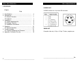
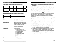
VGA to Video Ultimate Pro Copyright 2003. Black Box Corporation. All Rights Reserved 1000 Park Drive • Lawrence, PA 15055-1018 • 724-746-5500 • Fax 724-746-0746 Order toll-free in the U.S.: Call 877-877-BBOX (outside U.S. call 724-746-5500) CUSTOMER SUPPORT FREE technical support 24 hours a day, 7 days a week: Call 724-746-5500 or fax 724-746-0746 INFORMATION Mailing address: Black Box Corporation, 1000 Park Drive, Lawrence, PA 15055-1018 Web site: www.blackbox.com * E-mail: [email protected] TRADEMARKS AND LEGAL STATEMENT TRADEMARKS AND LEGAL INFORMATION AT, IBM, and PS/2 are registered trademarks of International Business Machines Corporation. RCA is a registered trademark of GE Co. OTHER LEGAL INFORMATION The information in this document is subject to change without notice and does not represent a commitment on the part of the developer. This document contains materials protected by copyright. All rights are reserved. No part of this manual may be reproduced or transmitted in any form, by any means or for any purpose without express written consent. FCC AND DOC/MDC STATEMENTS FEDERAL COMMUNICATIONS COMMISSION and CANADIAN DEPARTMENT OF COMMUNICATIONS RADIO FREQUENCY INTERFERENCE STATEMENT Class B Digital Device. This equipment has been tested and found to comply with the limits for a Class B computing device pursuant to Part 15 of the FCC Rules. These limits are designed to provide reasonable protection against harmful interference in a residential installation. However, there is no guarantee that interference will not occur in a particular installation. This equipment generates, uses, and can radiate frequency energy, and, if not installed and used in accordance with the instructions, may cause harmful interference to radio communications. If this equipment does cause harmful interference to radio or telephone reception, which can be determined by turning the equipment off and on, the user is encouraged to try to correct the interference by one of the following measures: • • • • Reorient or relocate the receiving antenna. Increase the separation between the equipment and receiver. Connect the equipment into an outlet on a circuit different from that to which the receiver is connected. Consult an experienced radio/TV technician for help. Caution: Changes or modifications not expressly approved by the party responsible for compliance could void the user’s authority to operate the equipment. To meet FCC requirements, shielded cables and power cords are required to connect this device to a personal computer or other Class B certified device. This digital apparatus does not exceed the Class B limits for radio noise emission from digital apparatus set out in the Radio Interference Regulation of the Canadian Department of Communications. Le présent appareil numérique n émet pas dr bruits radioélectriques dépassant les limites applicables aux appareils numériques de classe B prescrites dans le Règlement sur le brouillage radioélectriques publié par le ministére des Communications du Candada.. VGA to Video Ultimate Pro VGA to Video Ultimate Pro CONTENTS S-VIDEO OUT Chapter Page 1. Specifications…………………………………………………… 4 2. Introduction…………………………………………………….. 7 2.1 General Overview……………………………………….. 7 2.2 Features…………………………………………………….. 7 3. Installation………………………………………………………. 8 3.1 System Requirements…………………………………. 8 3.2 Package Contents………………………………………. 8 3.3 Installation Procedures……………………………….. 9 4. Operation………………………………………………………… 10 4.1 Remote Operation…………………………………………..11 5. Trouble-shooting………………………………………………. 12 5.1 Common Questions and Concerns………………… 12 6. Appendix: Connector Pin outs…………………..………. 15 3 ____________________________________________________________ S-VIDEO connector is a 4-pin mini-DIN connector. VIDEO OUT Composite video out, 1.0Vpp ± 0.2Vpp 75 ohms, negative sync. ____________________________________________________________ 16 VGA to Video Ultimate Pro APPENDIX: PORT PINOUTS Appendix: Port Pinouts 1. Specifications VGA IN/OUT connector This port is a DB15HD female connector and it supports only the included Y-cable. System Hardware Required - Pin No. 1 2 3 4 5 6 7 8 9 10 11 12 13 14 15 Computer of one of these types: • IBM PC Compatible, 286 or faster with VGA display card; or Mac G3/G4 or iMac with CRT port • TV set with one of these inputs: composite video, Svideo, component video, or (with modulator) RF Signal Description Red out, 0.7Vpp ± 0.1Vpp, 75 ohms, to monitor Green out, 0.7Vpp ± 0.1Vpp, 75 ohms, to monitor Blue out, 0.7Vpp ± 0.1Vpp, 75 ohms, to monitor DDC2B bus, SDA signal Green in, 0.7Vpp ± 0.1Vpp, 75 ohms, from PC Composite SYNC input, negative sync Monitor Sense, TTL level, active low Ground Red in, 0.7Vpp ± 0.1Vpp, 75 ohms, from PC Blue in, 0.7Vpp ± 0.1Vpp, 75 ohms, from PC HSYNC in, TTL level, from PC VSYNC in, TTL level, from PC HSYNC out, buffered HSYNC in, to monitor VSYNC out, buffered VSYNC in, to monitor DDC2B bus, SCL signal Compliance - FCC Class B, DOC Class/MDC Classe B Interfaces - Input: VGA Output: Composite video, S-video, Y.Cb.Cr component video, RGB, and VGA Color - Full color support, including 24-bit (true color) input VGA display modes Resolution Vertical Frequency (Hz) 15 ____________________________________________________________ 720 x 400 70 640 x 480 800 x 600 1024 x 768 1152 x 864 60, 70, 56, 60, 60, 70, 60, 70, 72, 75, 70, 72, 72,75 72,75 85, 100, 75, 85, 100 120 1280 x 960 1280 x 1024 1600 x 1200 60 60 60 _____________________________________________________________ 4 VGA to Video Ultimate Pro VGA to VIDEO Ultimate Pro MAC display modes(for MAC G4,G4 Cubic, G3) 640 x 480 832 x 624 60,66,72,75, 85,100,120 75 Resolution Vertical Frequency(Hz) 800 X 600 1152 X 864 1024 X 768 56,60,72, 60,70,75 75,85,100 60,70 APPLE iMac and iMAC DV computer display modes Resolution 640x480 800x600 1024x768 Vertical frequency (Hz) 117 95 75 Maximum Distance User Controls - 50 ft. (15.2 m) to any input or output device Remote controls for: Power, Video Standard, Area Zoom, Menu, Reset, Freeze, Up, Down, Left, Right (6) Side-mounted: (1) DB15HD female for computer video (IN/OUT); (1) (1) (1) (1) (1) Power - 5 A: Your display might be running in “Overscan” mode (placing portions of the picture beyond the boundaries of the screen’s visible area). This typically occurs because VGA graphics have more display lines than the TV can handle. Toggle through the H-SIZE and V-IZE settings in the MENU until you find the optimum setting for your application. NOTE The SIZE control allows the entire image to be displayed by reducing it and putting a crisp, black border around it. Use this control in situations where edges of the image would otherwise be lost due to overscanning. Q: There are noise lines on the TV picture. How do I get rid of them? 10 button remote control Connectors - Q: Why is the TV not displaying portions of the display when converted? RCA video output S-video output RGB to SCART output Y.Cb.Cr output DC In A: There are four settings in most televisions that affect the clarity of the display. The same adjustments can be used to improve the clarity of the display whether you use a converter or not. The settings are: 1. BRIGHTNESS: Typically, the brightness setting is by default too high. A high brightness setting often causes the display to flicker. 2. SHARPNESS: If the sharpness is set too high, often the result is what is termed “dot-crawl”, where the edges of the image appear to move. Lower the sharpness to soften the edges. 3. COLOR: If the color is set too high, often the result is colors that bleed or appear to sparkle. The high (purple) and low (red) frequency colors are most affected. Adjust the color setting down to soften the colors. 4. CONTRAST: If the contrast is set too high, often the result is exaggerated colors. Adjust the contrast down to complement the Sharpness setting. Unit: 5V DC Remote: 2 AAA batteries ____________________________________________________________ ___________________________________________________________ 14 VGA to VIDEO Ultimate Pro Q: I’m not getting a picture on my TV or all I see is a test pattern. VGA to VIDEO Ultimate Pro Temperature Tolerance - A: Take these steps: 1. The Y-cable connected between the VGA port on the computer and the VGA IN/OUT on the Internal Card is backwards. The end of the cable with the Y-connection should be connected to the Ultimate Pro. 2. Make sure the POWER and CHANNEL settings of your TV are correct. If the TV has a remote control, make sure it is not being triggered accidentally. 3. Make sure that the correct type of input (VIDEO or S-VIDEO) is selected on your TV. If possible, connect a VCR, camcorder or other output device to the TV’s video input and make sure that the TV is accepting input through the selected connector. Humidity Tolerance - Operating: +10°C to +40°C Storage: -17.8° to 43.3° C 8% to 80% noncondensing Size - 5” x 3”x 1.25” (12.5cm x 8cm x 3cm) Weight - .5 lb. (.23 kg) Q: When I connect my TV to the Ultimate Pro through a VCR, I get no picture on the TV. A: Take these steps: 1. Make sure your VCR is outputting on the channel that your TV can receive auxiliary input on. Consult your VCR’s manual if necessary. 2. Make sure that the VCR is set to receive input from the VIDEO IN or AUX. Q: I have DTV, EDTV or HDTV. Can I use the Y.Cb.Cr output to get a digital display optimized for my digital TV? A: No. The Y.Cb.Cr output is converting the analog progressive VGA signal into an analog interlaced signal for display on the TV. The Y.Cb.Cr output offers the best clarity for scan conversion, but it is not an analog to digital conversion. 13_______________________________________________ _________________________________________________________ 6 VGA to VIDEO Ultimate Pro VGA to VIDEO Ultimate Pro 2. Introduction 5. Trouble-shooting 2.1 General Overview This chapter tries to answer questions and concerns that can arise when you install and use the VGA to Video Ultimate Pro. It also describes what to do when you have problems with the unit that you can’t solve yourself. The VGA to Video Ultimate Pro is an external high-resolution computer-to-TV video converter. It transfers images from your computer for display on a TV or video projector of any size or for recording on a VCR of any type (VHS, VHS-C, 8mm or Beta.). The converter is completely hardware based – you don’t have to run any computer software to use the converter. Its easy installation and use, features and high-resolution display make it perfect for presentations, training, kiosks, education, and a host of other applications. 2.2 • • • • • • • 7 Features Latest generation filter technology brings you clear, 100% flicker-free video. Pure hardware design. Supports NTSC, NTSC-EIAJ, PAL-M, PAL-N, PAL, and PAL Combination-N video for the TV output. Zoom function allows areas of the screen to be enlarged for special emphasis. Adjustable vertical and horizontal position of image. Horizontal and vertical screen size control Three video output ports (Composite, S-video, and Component Video) 5.1 Common Questions and Concerns Q. My TV doesn’t have an RCA jack (composite-video connector). How can I connect the Ultimate Pro to the TV? A1: Check the TV – if it has a 4-pin mini-DIN connector for S-video input, use this type of video instead (the quality of the picture will be better anyway). A2: If your TV is hooked to a VCR, connect through the VCR as follows: 1. Install and interconnect the Ultimate Pro normally, but connect the composite-video cable to the VCR’s VIDEO IN jack instead of to the TV. 2. Turn on the VCR and the TV. Switch the TV to the channel that takes VCR inputs. Play a tape for a moment on the VCR to make sure that you can see the program on the TV screen, then remove the tape from the VCR. 3. Consult your VCR’s manual to find out how to set the “input source” mode for the VCR. (VCRs generally have two or three input sources: one called TV, CABLE, or TUNER; one called VIDEO IN or AUX; and occasionally one called TAPE.) Set the input source to VIDEO IN or AUX. Your TV should now display the images from the Ultimate Pro. A3: Another option is to use an RF-modulator: You can use an RF modulator (not included) to convert the Ultimate Pro’s composite-video signal to an RF signal and send that signal into the TV’s antenna (VHF/UHF) input. (The quality of the picture will not be as clear as using only the composite-video or S-video connections directly into the TV.) _______________________________________________ 12 ____________________________________________________________ CHAPTER 3: INSTALLATION 4.1 Remote Operation VGA to VIDEO Ultimate Pro 3. Installation 3.1 POWER : Toggle between power on and off. VIDEO STANDARD: Press this button to select your video system. It supports NTSC, NTSC-EIAJ, PAL-M, PAL-N, PAL, PAL-COMBINATION-N. MENU : Press this button to cyclically activate the functions. These functions are Fine Tune, H-SIZE, V-SIZE, Brightness, Contrast, Hue, Saturation, Flicker, OSD color & Save. ZOOM : Toggle between Zoom and Normal display. RESET: Press this button will reset the picture to factory settings. FREEZE: Toggle between Freeze and Normal display. POSITION buttons: Press up, down, left & right button to adjust the position of the TV display. These buttons also are used to make adjustments to the setting in the MENU. • • • System Requirements IBM PC Compatible, 286 or faster with VGA display card; or Mac G3/G4 or iMac with CRT port VGA monitor (optional for simultaneous display) TV, VCR, or large-screen display with composite video, Svideo, or component video input NOTE: The VGA to Video Ultimate Pro should support any VGA computer that has a vertical display frequency between 56 and 120 Hz. However, because video circuitry connectors and computer display cards differ widely among manufacturers and devices, we cannot guarantee that the Ultimate Pro will function correctly in any nonstandard application. 3.2 Package Contents . • • • • • • • • 11 ____________________________________________________________ ____________________________________________________________ VGA to Video Ultimate Pro Remote control (1) 9.8 ft (3m) S-video cable (1) 9.8 ft (3m) composite video cable (1) 3.5 ft (1 m) VGA Y-cable (2) AAA Batteries (2) Power cables (USB and PS/2) This user’s manual 8 VGA to VIDEO Ultimate Pro CHAPTER 5: OPERATION 3.3 Installation Procedures Installation (continued) Take these steps to install your Ultimate Pro: 1. Turn off your computer. 2. Plug the supplied VGA Y-cable (the end with the Yconnection) into your computer’s VGA output and the other end into the VGA IN/OUT of the Ultimate Pro. The ends of the cable are labeled to specify how to connect them. 3. If using a local monitor plug the monitor’s VGA cable into the short end of the Y-cable. 4A. If using the composite video output, plug one end of the included composite video cable into the Ultimate Pro’s VIDEO OUT and the other end into the VIDEO IN on your TV, VCR, etc. Make sure the output switch is set to CVBS. 4B. If using the higher quality S-video video output, plug one end of the included S-Video video cable into the Ultimate Pro’s S-VIDEO OUT and the other end into the S-VIDEO IN on your TV, VCR, etc. Make sure the output switch is set to CVBS. 4C. If using the RGBS video output, plug the DB9 end of an RGBS cable (not included) into the Ultimate Pro’s RGB VIDEO OUT. If the other end of this cable is a SCART connector, plug it into the SCART connector of your TV, VCR, etc. If, however, the other end of this cable has four BNC connectors, plug them into the RED, GREEN, BLUE, and SYNC connectors of the RGBS VIDEO IN port of your TV, VCR, etc. If you need an RGBS cable, contact your supplier for technical assistance. Make sure the output switch is set to RGB. 4D. If using the component (Y.Cb.Cr) video output, connect the included component video cable in the Ultimate Pro’s Y.Cb.Cr output and the other ends into the component video input of the video display. The cable and the plugs are color-coded for proper connection. Make sure the output switch is set to Y.Cb.Cr. 9 __________________________________________________ 5. Plug the output cord of the Ultimate Pro’s power cable into the DC IN jack on the Ultimate Pro. Plug the USB or PS/2 keyboard connector into the corresponding port on the PC. Macintosh users must use the USB power cable. 6. Insert (2) AAA batteries into the remote control. 7. Turn on the computer. 8. Turn on your TV, VCR, etc. If necessary, select VIDEO IN (or S-VIDEO IN, COMPONENT IN or RGBS VIDEO IN) as the receiving device’s video input source. If you’re unsure how this is done, consult the Owner’s Manual for the receiving device. NOTE Some portable computers require that the VGA output be activated for the external VGA port to function. If the Ultimate Pro is connected correctly and you have a picture on the receiving TV or projector, this may be the cause. Consult the User’s Guide that came with your computer if you’re unsure how this is accomplished. The portable computer’s LCD display may need to be de-activated with this procedure. 4. Operation z z z z z z HORIZONTAL / VERTICAL position adjustments Indicated by arrows on the side of the Ultimate Pro MENU Button Accesses the on screen display for adjusting Horizontal and Vertical size, Brightness, Contrast, Hue, Saturation, Flicker, OSD color and Reset. PAL/NTSC Toggle between each of the output video standards FINE TUNE Flicker adjustment SAVE Saves current settings for use between power-ups, etc. ZOOM button Toggle between Zoom and Normal display _ _________________________________________________________ 10