1
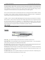
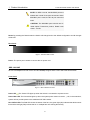
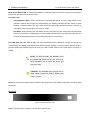
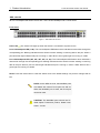
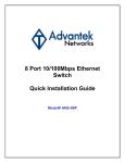
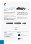
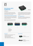
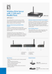
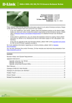
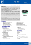
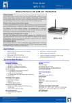
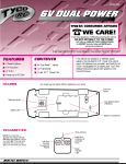
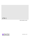
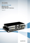
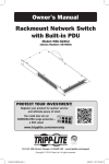
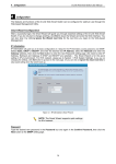
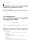
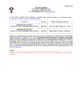
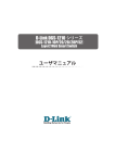
1
1
Product Introduction
D-Link Web Smart Switch User Manual
Product Introduction
Thank you and congratulations on your purchase of D-Link Web Smart Switch Products.
D-Link's next generation Web Smart Ethernet switch series blends plug-and-play simplicity with exceptional
value and reliability for small and medium-sized business (SMB) networking. All models are housed in a new
style rack-mount metal case with easy-to-view front panel diagnostic LEDs, and provides advance features
including two combo 1000BASE-T/SFP and two additional Gigabit uplinks, network security, traffic
segmentation, QoS and versatile management.
Flexible Port Configurations. D-Link Web Smart Switches offer four port configurations, 24/48 Ethernet
ports or 8/24 Ethernet ports with PoE support. All ports of the switch support auto MDI/MDIX feature which
bring inexpensive and easy Ethernet connection to the desktops. Each switch provides 4 Gigabit uplinks
connection to a Gigabit backbone or servers. Two of the Gigabit ports are SFP combo ports which support
both 1000M and 100M fiber connections.
Extensive Layer 2 Features. Implemented as complete Layer 2 devices, these switches include functions
such as IGMP Snooping, Port Mirroring, Spanning Tree, 802.3ad LACP and Loopback Detection to enhance
performance and network resiliency.
Traffic Segmentation and QoS. The switches support 802.1Q VLAN tagging to enhance network security
and performance. The switches also support 802.1p priority queues, enabling users to run
bandwidth-sensitive applications such as multimedia streaming by prioritizing traffic in network. These
functions allow switches to work seamlessly with VLAN and 802.1p traffic in the network. Auto Voice VLAN
automatically places the voice traffic from IP phone to an assigned VLAN with higher priority, separating from
normal traffic. Asymmetric VLAN is implemented in these switches for a more efficient use of shared
resources such as server or gateway devices.
Network Security. D-Link’s innovative Safeguard Engine function protects the switches against traffic
flooding caused by virus attacks. Additional feature like 802.1X port-based authentication provides access
control of the network with external RADIUS servers. ACL is a powerful tool to screen unwanted IP or MAC
traffic. Storm Control keeps the network from being overwhelmed by abnormal traffic. Port Security is another
simple but useful authentication method to maintain the integrity of the network device.
Versatile Management. The new generation of D-Link Web Smart Switches provides growing businesses
simple and easy management of their network. The SmartConsole utility or a multi-language Web-Based
management interface allows administrators to remotely control their network down to the port level. The
intuitive SmartConsole easily allows customers to discover multiple D-Link web smart switches in the same
2
1
Product Introduction
D-Link Web Smart Switch User Manual
L2 network segment. With this utility, users do not need to change the IP address of PC and provides easy
initial setting of smart switches. The switches within the same L2 network segment connected to user’s local
PC are displayed on the screen for instant access. It allows extensive switch configuration setting, and basic
configuration of discovered devices such as a password change or firmware upgrade.
Users can also access the Switch via Telnet. Basic tasks such as changing the Switch IP address, resetting
the settings to factory defaults, setting the administrator password, rebooting the Switch, or upgrading the
Switch firmware can be performed using the Command Line Interface (CLI).
In addition, users can utilize the SNMP MIB (Management Information Base) to poll switches for information
about the status, or send out traps of abnormal events. SNMP support allows users to integrate the switches
with other third-party devices for management in an SNMP-enabled environment. D-Link Web Smart
Switches also come with the D-View plug-in module that works with D-View 6, SNMP Management Software
which provides easy-to-use graphic interface and facilitates the operation efficiency.
DES-1210-08P
8-Port 10/100Mpbs PoE Web Smart Switch
Front Panel
Figure 1 – DES-1210-08P Front Panel
Power LED : The Power LED lights up when the Switch is connected to a power source.
Power Max LED: The Power Max lights up when the system power resource remain ≦7W, in the meantime,
system will not provide power to the additional PoE PD inserted.
Fan OK/Fail LED: The FAN LED shows the status of the fans, the green light (OK) indicates that all fans work
fine and the red light (Fail) indicate that on or multiple fans are working abnormally.
PoE LED (1-8): The PoE LED lights up with solid green indicates power device is connected to corresponding
port. Solid amber indicates a PoE error has occurred at this port. And light off indicates this port is not
providing the power or no PD found.
Port Speed LED (1-8): The Port Speed LED lights up with solid green indicate the corresponding port is
running on 100M. Light off indicated that port is running on 10M.
3
1
Product Introduction
D-Link Web Smart Switch User Manual
Port Link/Act LED (1-8): The Link/Act LED lights up with solid green indicate a network link through the
corresponding port. Blinking indicates that the Switch is either sending or receiving data to the port.
Reset: By pressing the Reset button the Switch will change back to the default configuration and all changes
will be lost.
Rear Panel
Figure 2 – DES-1210-28 Rear Panel
DC Power Jack: The power jack is where to connect the DC power cord of power adapter.
Power Switch: Use to turn on/off the Switch.
DES-1210-28
24-Port 10/100Mpbs with 4-Port 10/100/1000Mbps Copper and 2 Combo SFP Web Smart Switch
Front Panel
Figure 3 – DES-1210-28 Front Panel
Power LED : The Power LED lights up when the Switch is connected to a power source.
Port Link/Act/Speed LED (1-24): The Link/Act/Speed LED flashes which indicates a network link through the
corresponding port. Blinking indicates that the Switch is either sending or receiving data to the port. When a
port has amber light indicates that port is running on 10M. When it has a green light it is running on 100M.
Port Link/Act/Speed LED (25F, 26F, 25T, 26T, 27, 28): The Link/Act/Speed LED flashes which indicates a
network link through the corresponding port. Blinking indicates that the Switch is either sending or receiving
data to the port. When a port has amber light indicates that port is running on 10M or 100M. When it has a
green light it is running on 1000M.
4
1
Product Introduction
D-Link Web Smart Switch User Manual
NOTE: On DES-1210-28, the MiniGBIC ports are
shared with normal RJ-45 ports 25 and 26. When
MiniGBIC port is used, the RJ-45 port cannot be
used.
CAUTION: The MiniGBIC ports should use UL
listed Optical Transceiver product, Rated Laser
Class I. 3.3Vdc.
Reset: By pressing the Reset button the Switch will change back to the default configuration and all changes
will be lost.
Rear Panel
Figure 4 – DES-1210-28 Rear Panel
Power: The power port is where to connect the AC power cord.
DES-1210-28P
24-Port 10/100Mpbs PoE with 4-Port 10/100/1000Mbps Copper and 2 Combo SFP Web Smart Switch
Front Panel
Figure 5 – DES-1210-28P Front Panel
Power LED : The Power LED lights up when the Switch is connected to a power source.
Power Max LED: The Power Max lights up when the system power resource remain ≦7W, in the meantime,
system will not provide power to the additional PoE PD inserted.
Fan OK/Fail LED: The FAN LED shows the status of the fans, the green light (OK) indicates that all fans work
fine and the red light (Fail) indicate that on or multiple fans are working abnormally.
5
1
Product Introduction
D-Link Web Smart Switch User Manual
Mode Select Button/LED: The Mode Select Button controls the mode of Port LED, and the current setting is
indicated by the Mode LED under the button.
Port LED (1-24):
Link/Act/Speed Mode: When selecting the Link/Act/Speed Mode, the Port LED flashes which
indicate a network link through the corresponding port. Blinking indicates that the Switch is either
sending or receiving data to the port. When a port has amber light indicates that port is running on
10M. When it has a green light it is running on 100M.
PoE Mode: When selecting the PoE Mode, the port LED lights up with solid green indicates power
device is connected to corresponding port. Solid amber indicates a PoE error has occurred at this port.
And light off indicates this port is not providing the power or no PD found.
Port LED (25F, 26F, 25T, 26T, 27, 28): The Port LED flashes which indicates a network link through the
corresponding port. Blinking indicates that the Switch is either sending or receiving data to the port. When a
port has amber light indicates that port is running on 10M or 100M. When it has a green light it is running on
1000M.
NOTE: On DES-1210-28P, the MiniGBIC ports
are shared with normal RJ-45 ports 25 and 26.
When MiniGBIC port is used, the RJ-45 port
cannot be used.
CAUTION: The MiniGBIC ports should use UL
listed Optical Transceiver product, Rated Laser
Class I. 3.3Vdc.
Reset: By pressing the Reset button the Switch will change back to the default configuration and all changes
will be lost.
Rear Panel
Figure 6 – DES-1210-28P Rear Panel
Power: The power port is where to connect the AC power cord.
6
1
Product Introduction
D-Link Web Smart Switch User Manual
DES-1210-52
48-Port 10/100Mpbs Web Smart Switch with 4-Port 10/100/1000Mbps and 2 Combo SFPs
Front Panel
Figure 7 – DES-1210-52 Front Panel
Power LED : The Power LED lights up when the Switch is connected to a power source.
Port Link/Act/Speed LED (1-48): The Link/Act/Speed LED flashes which indicates a network link through the
corresponding port. Blinking indicates that the Switch is either sending or receiving data to the port. When a
port has amber light indicates that port is running on 10M. When it has a green light it is running on 100M.
Port Link/Act/Speed LED (49F, 50F, 49T, 50T, 51, 52): The Link/Act/Speed LED flashes which indicates a
network link through the corresponding port. Blinking indicates that the Switch is either sending or receiving
data to the port. When a port has amber light indicates that port is running on 10M or 100M. When it has a
green light it is running on 1000M.
Reset: Press the reset button to reset the Switch back to the default settings. All previous changes will be
lost.
NOTE: On the DES-1210-52, the MiniGBIC ports
are shared with normal RJ-45 ports 49 and 50.
When the MiniGBIC port is used, the RJ-45 port
cannot be used.
CAUTION: The MiniGBIC ports should use UL
listed Optical Transceiver product, Rated Laser
Class I. 3.3Vdc.
7
1
Product Introduction
D-Link Web Smart Switch User Manual
Rear Panel
Figure 8 – DES-1210-52 Rear Panel
Power: Connect the supplied AC power cable to this port.
8