1
X-600MTitle
Page Goes
Here
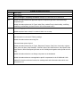
X-600M User Manual Revisions
Revision Description
1.0
Initial release
1.1
Changed Assign a Temporary IP Address example from Windows-XP to Windows-8
1.2
Added information about new Application Specific component type and Custom Web Page
component type.
Added information about new I/O Types: indoorTemp, outdoorTemp, indoorHumidity, coolRelay,
heatRelay, and fanRelay (all found on the X-300 in thermostat mode.)
1.3
Corrected logging screenshot labels.
Added text about how to check if a number is NaN in a Lua script.
1.4
Corrected wireless adapter information.
Add information on the new IP Filtering settings.
Added information about external log files.
Corrected erase system log's url
Added information about new I/O Types: Barometric Pressure, Dew Point, Heat Index, Irrigation
Valve, Rain Last Hour, Solar Radiation, Total Rain, Wind Chill, Wind Direction, Wind Speed, Wind
Gust Direction, Wind Gust Speed (all found on the X-320M), and Irrigation valves (found on the X340).
Added information about the new Gauge component on the dashboard.
Added information about two new application specific components for the X-320M and X-340.
Updated LUA section with new functions for sending emails with information about which user
accessed an I/O.
X-600M Users Manual
Table of Contents
Section 1: Introduction......................................................................................................................................... 5
1.1 X-600M™ Features................................................................................................................................... 6
1.2 Applications.............................................................................................................................................. 8
1.3 Accessing X-600M.................................................................................................................................... 9
1.4 Connectors & Indicators.......................................................................................................................... 9
1.5 Security..................................................................................................................................................... 9
1.6 X-600M, Accessories, and Expansion Models..................................................................................... 10
Section 2: Installation and Wiring..................................................................................................................... 12
2.1 Installation Guidelines........................................................................................................................... 12
2.2 Mounting................................................................................................................................................. 12
2.2.1 Wall Mounting.................................................................................................................................... 12
2.2.2 DIN-Rail Mounting............................................................................................................................. 12
2.3 Making Wiring Connections.................................................................................................................. 13
2.3.1 Wiring Procedure:.............................................................................................................................. 13
2.3.2 Power Supply Connections................................................................................................................ 13
2.3.3 System Start Up................................................................................................................................. 14
2.3.4 Expansion Module Connections........................................................................................................ 14
2.3.5 Optional Power Injector..................................................................................................................... 15
2.3.6 Temperature/Humidity Sensor Connections....................................................................................... 15
2.3.7 Network Connection.......................................................................................................................... 17
2.3.8 External USB Flash Drive.................................................................................................................. 17
Section 3: Configuration and Setup.................................................................................................................. 18
3.1 Establishing Communications Over Wired Network........................................................................... 18
3.1.1 Method 1: Use DHCP and NetBios.................................................................................................... 18
3.1.2 Method 2: Assign a Temporary IP Address to the Configuration Computer.......................................19
3.2 Establishing Communications Over a Wireless Network................................................................... 23
....................................................................................................................................................................... 23
3.2.1 Ad-Hoc Wireless Connection............................................................................................................. 23
3.2.2 Wireless Connection Using Access-Point.......................................................................................... 23
3.3 Configuration and Setup Access.......................................................................................................... 24
3.4 Basic Setup Strategy.............................................................................................................................. 24
3.5 Setup Example........................................................................................................................................ 26
3.6 Making Changes..................................................................................................................................... 28
3.7 Dashboard Access - Users and Access Groups.................................................................................. 29
3.7.1 Access Groups................................................................................................................................... 29
Section 4: Setup Pages...................................................................................................................................... 31
4.1 System Tab............................................................................................................................................. 31
4.1.1 System > Access Groups (Edit access groups)................................................................................. 32
4.1.2 System > User Accounts (Add, edit, and delete user accounts)........................................................ 33
4.1.3 System > Date & Time (Configure system date and time)................................................................. 35
4.1.4 System > Backup/Restore (Backup and Restore Settings)................................................................37
4.1.5 System > SSL Certificates................................................................................................................. 38
Default Self-Signed SSL Certificate
Generating a New Certificate
Signing Certificates with a Certificate Authority
Xytronix Research & Design, Inc.
Page 1
X-600M Users Manual
Importing self-signed certificates
4.1.6 System > Custom Web Pages........................................................................................................... 40
4.1.7 System > System Log........................................................................................................................ 42
4.2 Network Tab (Current network configuration of a device).................................................................. 43
4.2.1 Network > Ethernet (Configure Ethernet Settings)............................................................................. 43
4.2.2 Network > Wireless (Configure wireless adapter).............................................................................. 45
4.2.3 Network > Advance Network Tab....................................................................................................... 47
Network > Advance Network > Web Server (Configure web server settings)
Network > Advanced Network > Modbus (Configure Modbus settings)
Network > Advanced Network > Remote Services Server (Configure remote services server)
Network > Advanced Network > Remote Services Client (Configure remote services client settings)
Network > Advanced Network > SNMP (Configure device to communicate with SNMP manager)
Network > Advanced Network > Email (Configure Email (smtp) settings)
Network > Advanced Network > FTP (Configure FTP settings)
Network > Advanced Network > NetBIOS / mDNS (Setup)
4.3 Devices Tab............................................................................................................................................. 55
4.3.1 Devices > Find New Devices............................................................................................................. 57
4.4 I/O Tab (Add, edit and delete I/O).......................................................................................................... 58
4.4.1 I/O > 1-Wire Sensors (Add, edit and delete 1-wire sensors).............................................................. 61
4.4.2 I/O > Registers (Add, edit, and delete Registers).............................................................................. 63
4.4.3 I/O > Serial Ports (Add, Edit, and Delete Serial Ports)....................................................................... 65
4.5 Control/Logic Tab................................................................................................................................... 68
4.5.1 Control/Logic > Conditional Events.................................................................................................... 68
Digital Event
Analog Event
Complex Event
4.5.2 Control/Logic > Calendar Events....................................................................................................... 71
4.5.3 Control/Logic > Actions (Add, edit, and delete Actions)..................................................................... 75
4.5.4 Control/Logic > Scripts (Add, edit, and delete Scripts).......................................................................78
4.6 Logging Tab............................................................................................................................................ 82
4.7 Edit Dashboards Tab.............................................................................................................................. 85
4.7.1 Edit Dashboards (Add dashboard)..................................................................................................... 85
4.7.2 Edit Dashboards (Add Panel)............................................................................................................ 86
4.7.3 Edit Dashboards (Add Widget).......................................................................................................... 87
4.7.4 Edit Dashboards (Add Component)................................................................................................... 89
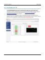
4.8 View Dashboards Tab............................................................................................................................ 99
Section 5: Modbus Operation.......................................................................................................................... 100
5.1 X-600M Function Code Summary....................................................................................................... 101
5.2 PLC Device Addressing....................................................................................................................... 101
5.3 Modbus Function Codes...................................................................................................................... 103
5.3.1 Read Coils - Modbus Function Code 01 (0x01)............................................................................... 103
5.3.2 Read Discrete Inputs – Modbus Function Code 02 (0x02).............................................................. 104
5.3.3 Read Holding Register – Modbus Function Code 03 (0x03)............................................................ 104
5.3.4 Write Single Coil – Modbus Function Code 05 (0x05)..................................................................... 105
5.3.5 Write Multiple Coils - Modbus Function Code 15 (0x0F).................................................................. 105
5.3.6 Write Multiple Registers – Modbus Function Code 16 (0x10).......................................................... 106
Section 6: XML/JSON Operation..................................................................................................................... 107
6.1 XML/JSON Monitor............................................................................................................................... 107
6.2 XML/JSON Control............................................................................................................................... 108
Page 2
Xytronix Research & Design, Inc.
X-600M Users Manual
Section 7: Email Notification............................................................................................................................ 110
7.1 Email Notification................................................................................................................................. 110
7.2 Email Notification Setup...................................................................................................................... 110
Appendix A: Restoring Factory Default Settings........................................................................................... 112
Appendix B: Installing New Firmware............................................................................................................. 113
Appendix C: Accessing X-600M Over the Internet......................................................................................... 115
Appendix D: Log Files...................................................................................................................................... 119
Appendix E: External Server and Remote Services...................................................................................... 121
Appendix F: SNMP Requests, Objects and Security..................................................................................... 123
Appendix G: Lua Scripts.................................................................................................................................. 124
Appendix H: Custom Web Pages.................................................................................................................... 135
Appendix I: Specifications............................................................................................................................... 145
Appendix J: Trademark and Copyright Information...................................................................................... 148
Appendix K: Warranty...................................................................................................................................... 149
Appendix L: FCC Statement............................................................................................................................ 150
Appendix M: Licensing..................................................................................................................................... 151
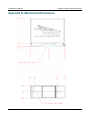
Appendix N: Mechanical Dimensions............................................................................................................. 152
Xytronix Research & Design, Inc.
Page 3
X-600M Users Manual
Page 4
Xytronix Research & Design, Inc.
X-600M Users Manual
Introduction
Section 1: Introduction
The X-600M™ is a multifunction web-enabled industrial I/O controller. The X-600M performs control,
logic, and monitoring functions similar to that of a Programmable Logic Controller (PLC). However,
unlike a PLC, the X-600M is designed for web based applications from the ground up. No add-on
software or hardware is required. The X-600M can be fully configured, programmed and tested using its
built-in web server. The web page setup is intuitive, easy to use, and does not require special
programming skills.
Many control and monitor applications begin by selecting a Programmable Logic Controller or similar
hardware device. You must then write the control logic in ladder-logic or other vendor specific
programming language. Next, you must purchase and develop a graphical user interface to run on a PC
or design a web page with dynamic content for the control and status elements. Finally you must specify
and test the communications between the graphical user interface and the control device. This
specialized work is often done by system integrators and others with the necessary skills and software.
With the X-600M you can bypass all of this work. The X-600M comes out of the box with a web server,
IP communications and working web pages. In a few minutes you can turn relays on and off, monitor
analog sensors, and check the status of digital inputs. With a little experimentation you can re-arrange
the web page format and customize the buttons and status fields with your own labels.
In comparison to other ControlByWeb™ products, the X-600M does not have built in relays or digital
inputs. Instead, it functions as a powerful master “controller” for other ControlByWeb modules. The X600M can control and monitor devices such as the WebRelay™, WebRelay-Quad™, X-310™, X-320™,
etc. anywhere on the Internet. In addition, the X-600M has a ribbon cable expansion bus connector
which allows a family of add-on modules to be connected directly to the X-600M. Expansion modules
are available with relays, digital inputs, thermocouples and other industrial inputs and outputs. Up to 64
expansion modules can be connected directly to the X-600M with a ribbon cable. The X-600M can
control and monitor a mix of expansion modules and ControlByWeb devices up to a maximum of 128
total devices.
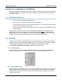
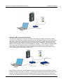
The X-600M can be controlled and/or monitored over any Ethernet
network including private networks, and the Internet. Users can
operate the X-600M using a web browser, or custom applications
can be written to control the X-600M from a computer, PLC, or other
automation controller. In addition, custom control scripts are
supported using the Lua scripting language. Lua is a lightweight,
extensible programming language used in many industrial
applications.
Many powerful features are integrated into the X-600M including:
Email notification (encrypted and non-encrypted), event scheduling,
logging, and graphing. The X-600M supports a number of Ethernet
protocols including HTTP, HTTPS, Modbus/TCP, SNMP, NTP, SMTP,
FTP, XML and JSON.
Xytronix Research & Design, Inc.
Page 5
Introduction
X-600M Users Manual
1.1 X-600M™ Features
Xytronix Research & Design continually works to improve its products in response to customers needs
and suggestions. The X-600M is a new revolutionary product which employs a powerful processor
together with industrial Flash memory. With increased processing power, applications such as sending
encrypted Email and wireless access are now feasible in a small industrial package.
High Reliability Design
Designed from the ground up for reliability rather than cost optimization. Built with industrial grade,
wide temperature range components. Uses Industrial grade SLC (Single Level Cell) flash memory
which offers higher reliability than the ultra dense components used in consumer products such as
cell phones. Includes transient protection on all I/O. Includes circuitry for reliability and protection
such as an independent hardware watchdog and voltage supervisor.
Easy Start Up
After making the power and Ethernet connections, you can have the X-600M automatically scan for
the presence of any ControlByWeb Ethernet modules (on the same sub-net) and for any expansion
modules connected to the X-600M ribbon cable connector. You can also automatically create a
“Dashboard” web page and populate it with all of the resources (components) supported by the
Ethernet and expansion modules. This makes it easy to start experimenting with the web page user
interface and to try out the relays and sensors.
Expandable
The X-600M provides a flexible, system level solution for monitoring and control. The X-600M can
control and monitor remote devices such as the WebRelay, WebRelay-Quad, X-310, X-320, etc.
anywhere on the Internet. A family of add-on modules can be connected directly to the X-600M.
Remote devices and expansion modules are added as needed to provide a customizable and highly
flexible monitoring and control system.
File System
The Flash file system provides a major upgrade in flexibility and capability for web based control and
monitoring. With the embedded file system, users can add custom web pages. The file system
allows data to be logged to multiple named files. Setups can be imported and exported as a file.
Dashboards, Panels, Widgets and Components
The X-600M serves dynamic web pages which are used to control and monitor relays, sensors and
other I/Os. The control/status pages are called Dashboards and are highly flexible. The user can
create multiple dashboards as needed and customize them by placing panels, widgets and
components on the dashboard. Panels are used to group widgets together. Widgets are used to
group components together. A component is the smallest unit found on a dashboard and represents
a single I/O (a relay or temperature sensor for example.) The dashboards, panels, widgets, and
components can have custom labels. The web pages can be created, edited and tested directly from
the web browser.
A widget can represent a single external device such as a WebRelay or X-12s Eight-relay module,
or a widget may be composed of components which represent I/Os found on many different devices
across the network. Within a widget the user places components. A component can be an on/off
button with a custom label, a temperature readout, or other resources. Components are available for
control, status, and graphing. Components can be buttons, sliders, spinners, display boxes and
graphs.
Page 6
Xytronix Research & Design, Inc.
X-600M Users Manual
Introduction
Ethernet Switch
The X-600M has two IEEE std 802.3 Ethernet connectors with an internal L2 switch. The internal
Ethernet switch allows multiple modules to be daisy chained together or a second Ethernet device to
be connected without the need for an external Ethernet hub or switch. The X-600M does not tie up
an Ethernet port. Normally when two ports of the same configuration are connected, an Ethernet
crossover cable is needed to cross the transmit and receive signals in the cable. With the X-600M
both Ethernet connectors support Auto MDI-X which automatically detects the required cable
connection type and configures the connection appropriately.
Wireless Options
Plug an IEEE 802.11/B/G/N WIFI module into the USB Host connector and the X-600M can connect
to a wireless access point. The X-600M also supports a wireless “ad hoc” network which allows you
to connect directly to the X-600M with a smart phone, tablet, or PC.
USB Host and Device Connectors
The USB 2.0 Host controller allows connectivity with industry standard computer peripherals.
Currently the X-600M has support for USB flash memory drives and WIFI adapters.
1-Wire bus
Connector terminals provide communication with 1-wire sensors to monitor temperature and
humidity. A 1-wire ultrasonic sensor is also available for measuring distance or liquid levels.
Internal Temperature Sensor
An internal digital temperature sensor measures the internal temperature (-40°C to +85°C). This
sensor can be accessed from the overview page.
Expansion Bus
A ribbon cable expansion bus connector allows a family of add-on modules to be connected directly
to the X-600M without the need for an Ethernet switch. Various expansion modules are available
with relays, digital inputs, thermocouples and other industrial inputs and outputs. The ribbon cable
provides both communication and power connections to the expansion modules. The expansion bus
can provide up to 1.7 Amps for powering the attached expansion modules. The maximum number of
expansion modules depends on the module type and power requirements. The input current for the
various expansion modules is listed in the expansion module user manuals.
Power Supply
The X-600M works with 9 to 28V DC power. The power supply voltage (Vin+) is monitored internally.
This value can be displayed, logged, and used to control local/remote relays. It can also be
configured to send Email notifications. This feature is convenient for monitoring the system battery in
solar powered applications.
Real-time Clock
The real time clock is powered with an internal super capacitor which provides backup power for a
minimum of 30-days (no internal batteries need to be maintained). The time and date can be set
manually, or a time server can be used to periodically sync the time.
Event Scheduler
Program up to 1024 calendar events using a familiar calendar-based configuration page.
Automatically switch from weekday to weekend or holiday schedules.
Logging
Periodic and event based logging of any of the I/O configured on the X-600M is possible. Up to 5
separate log files can be created and stored either internally or externally on a USB flash drive.
Xytronix Research & Design, Inc.
Page 7
Introduction
X-600M Users Manual
Graphing
Logged data can be graphed directly inside any HTML 5 compatible web browser by adding a graph
component to any widget on the dashboard.
Email and Text Notification
Send Email and text alerts based on any sensor or input conditions, such as temperature, time,
frequency, digital inputs, power supply levels, and more. Text messages are sent through a cell
phone through a wireless carrier's Email bridge. Emails can be sent using SMTP servers requiring
SSL/TLS encryption. Send Emails to an individual user or to all members of an Access Group.
Scripts
Much flexibility and advanced control is provided through custom scripts using powerful easy-tolearn Lua scripts. The scripting language can be used to generate custom alarm conditions and
specialized control functions.
Web Server and Protocols
Simple web pages to display monitoring and control dashboards can be made by using drag-anddrop tools in the setup pages. In addition, custom pages can be created from scratch using HTML,
CSS, and Javascript. The X-600M supports both HTTP and HTTPS protocols. Additional
communication options include Modbus/TCP, and SNMP.
Access Groups
Users can be assigned to one of five Access Groups. Each group is assigned specific access
privileges. Access groups can be used to limit what control users might have. For example, the X600M might be used as a thermostat. The administrators can configure upper and lower limits on the
set temperature, while other users might only be able to adjust the set temperature within that range.
1.2 Applications
The X-600M was designed to meet a broad range of industrial applications. It works well as a standalone
device or system that can be controlled using a web browser. It is also a convenient way to add I/O to a
computer. It can be configured using simple menus and drop-down lists, or it can run Lua scripts. Many of its
features such as scheduling, logging, input state monitoring, and the ability to control external relays on
other devices, make the X-600M a very powerful, yet simple controller.
You can use the X-600M to control motors, lights, coils, pumps, valves, bells, etc. You can also use it to
monitor alarms sensors, switches, fluid level switches, battery voltage, temperature, humidity, and much
more. A few example applications include:
Page 8
•
Server or telemetry system “watchdog”
•
I/O Extender for a PLC
•
Industrial Thermostat
•
Solar Energy Controller
•
Process Monitor
•
Server for other ControlByWeb products: provide a single web page which controls other
ControlByWeb devices.
•
Process Controller
Xytronix Research & Design, Inc.
X-600M Users Manual
Introduction
1.3 Accessing X-600M
The X-600M has a built-in web server that provides simple web pages that can be accessed directly
using a standard web browser. This allows users to access the unit with NO SPECIAL SOFTWARE
installed on their computer. The configuration is simple to setup, simple to use, and can be accessed
from just about any computer or smart phone.
Note: Network routers may need to be configured to allow access from computers outside of the local
network (see Appendix C: Accessing X-600M Over The Internet).
1.4 Connectors & Indicators
Network Connectors
The X-600M has two RJ-45 Ethernet connectors. An internal L2 switch allows multiple modules to
be daisy chained together or second Ethernet device to be connected without the need for an
external Ethernet hub or switch. The green LINK LED is illuminated when the module is properly
connected to an Ethernet network and is ready to communicate. Network communications will only
occur if this LED is illuminated. The LINK LED blinks when activity is detected on the network. The
yellow 10/100 speed LED is illuminated when the network speed is 100Mbps.
Normally when two ports of the same configuration (MDI to MDI or MDI-X to MDI-X) are connected,
an Ethernet crossover cable is needed to cross the transmit and receive signals in the cable. With
the X-600M both Ethernet connectors support Auto MDI-X which automatically detects the required
cable connection type and configures the connection appropriately. The X-600M can be connected
to either a hub/switch or a computer with a straight-thru connector. There is no need for a special
crossover cable when making connections directly to a computer.
I/O Connector
A 5-position plug-in screw terminal connector is used to provide power to the module and
connections for external 1-wire temperature/humidity sensors.
Expansion Bus Connector
A ribbon cable expansion bus connector allows for a family of expansion modules to be directly
connected to the X-600M. The ribbon cable provides both communication and power connections to
the expansion modules. The cable can be a daisy chain with multiple connectors.
USB Host Connector (Type A)
The USB2.0 Host controller allows connectivity with industry standard computer peripherals. The X600M has support for USB flash memory drives and WIFI adapters.
USB Device Connector(mini-B)
The USB Device connector is primarily used for firmware upgrades.
Power Indicator
The green Power LED indicator is illuminated whenever the module is powered.
1.5 Security
The X-600M has built in security features normally employed with industrial applications. The operating
system is stored in a read-only file partition and cannot be changed or “hacked” by malicious users. The
Xytronix Research & Design, Inc.
Page 9
Introduction
X-600M Users Manual
device supports multiple communication protocols such as FTP (client only), SNMP, and Modbus over
TCP/IP, but these ports are only open when the service has been enabled. By default, the only ports that
are open are 80 and 443, which are the web server ports. If Dashboard and I/O protection is enabled,
users must log in using a predetermined username and password. This authentication takes place over
an encrypted connection when using HTTPS.
The simplicity of the X-600M makes it an inherently secure device. Nevertheless, as with any device
installed on a network, appropriate security precautions should be observed. If the X-600M is installed
on the Internet, it is recommended that the device only be accessed using HTTPS so that all
communication with the device is encrypted.
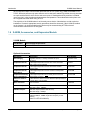
1.6 X-600M, Accessories, and Expansion Models
X-600M Module
Part Number
Power Supply Requirements
X-600M-I
9-28VDC
Optional Accessories
Page 10
Accessory
Description
Part Number
Power Supply
Regulated, 24V DC, 1.75Amp, 100-240V AC Input,
DIN mount
PS24VW1.75-B
Temperature Sensor
1-Wire Digital temperature sensor with 12 inch wire leads.
Note: Leads may be extended
X-DTS-U
Temperature Sensor
1-Wire Digital temperature sensor with 36 inch weather
resistant cable
X-DTS-S3C
Temperature Sensor
(Wall Mount)
1-Wire Digital temperature sensor housed in vented plastic
enclosure
X-DTS-WM
Temperature/Humidity
Sensor (Wall Mount)
1-Wire Digital temperature and humidity sensor housed in
vented plastic enclosure
X-DTHS-WM
Ultrasonic distance
sensor
1-Wire Ultrasonic distance sensor. Measure object proximity to
5-meters with 1-mm resolution.
Spare Connector
5-Pin Connector
USB WiFi Adapter
USB WIFI adapter (ASUS USB-N10)
IEEE 802.11 b/g/n, 150Mbps
USB WiFi Adapter
USB WIFI adapter (EDImax EW-7811Un)
IEEE 802.11b/g/n, 150Mbps
USB Flash Drive
USB Flash Drive, industrial temperature range (-40°C to 85C),
Hi-Speed USB 2.0, 128MB, single level cell (SLC), 5-Year
warranty
(Delkin UY12TFJSY-XN000-D)
X-1827004
Xytronix Research & Design, Inc.
X-600M Users Manual
Introduction
Expansion Modules and Accessories
See www.ControlByWeb.com for an up-to-date list of available expansion modules and accessories.
Expansion Module
Description
Part Number
X-11s
2-Relay module, Form C (SPDT), 20Amp, 277VAC,
with mating connector
X-11s
X-12s
8-Relay module, Form C (SPST), 2.5-Amp, 120VAC, with
mating connector
X-12s
X-13s
2-Channel thermocouple module, Type-K, -200°C to 1250°C
(thermocouple not included)
X-13s-K
X-15s
8-Channel input module, optically isolated
X-15s
X-16s
Analog module, 8-channel, 0-5V, 24-bit, single or differential
inputs, 5V reference output
X-16s
Expansion Cable
10-conductor ribbon cable with connectors,
1-32 positions, 2.5-inches between connectors
For example:
EXPCBL-1 for 1 expansion module (cable with 2-connectors)
EXPCBL-2 for 2 expansion modules (cable with 3-connectors)
EXPCBL-3 for 3 expansion modules (cable with 4-connectors)
EXPCBL-X
(where X=1-32)
Power Injector
Optional connector module for supplying external power to the
expansion bus ribbon cable
Accessories
Xytronix Research & Design, Inc.
X-PINJECT
Page 11
Installation and Wiring
X-600M Users Manual
Section 2: Installation and Wiring
Installation consists of mounting the X-600M, connecting it to an Ethernet network, and providing power.
The setup is completed by using the web browser to configure the web pages, inputs, and outputs for
your specific needs.
2.1 Installation Guidelines
•
This unit must be installed by qualified personnel.
•
This unit must not be installed in unprotected outdoor locations.
•
This unit must not be used for medical, life saving purposes, or for any purpose where its failure
could cause serious injury or the loss of life.
•
This unit must not be used in any way where its function or failure could cause significant loss or
property damage.
This equipment is tested to UL 61010-1 safety requirements for equipment to be supplied from the
building wiring (i.e. thru a circuit breaker). It is not rated for installation within or as part of the circuit
breaker panel. When used with expansion modules to control AC line voltages, the X-600M and the
expansion modules must be mounted and protected in a suitable electrical enclosure.
2.2 Mounting
X-600M can be mounted to a standard (35mm by 7.55mm) DIN-Rail. Or it can also be wall mounted. It
should be located in a clean, dry location (NEMA 4) where it is protected from the elements. Ventilation
is recommend for installations where ambient air temperatures are expected to be high
See Appendix N: Mechanical Information for additional mechanical details.
2.2.1 Wall Mounting
Mount the X-600M to a wall by using two #8 screws. Attach the screws to the wall vertically spaced
exactly 2.5 inches apart. The head of the screw should be about 1/10 inch away from the wall.
2.2.2 DIN-Rail Mounting
Attach the X-600M to the DIN-Rail by hooking the top hook on the back of the enclosure to the DIN-Rail
and then snap the bottom hook into place. To remove the X-600M from the DIN-Rail, use a flat-head
screwdriver. Insert the screw driver into the notch in the release tab and pry against the enclosure to
release the bottom hook.
Page 12
Xytronix Research & Design, Inc.
X-600M Users Manual
Installation and Wiring
2.3 Making Wiring Connections
MIS-WIRING OR MIS-CONFIGURATION COULD CAUSE PERMANENT DAMAGE
TO THE X-600M, THE EQUIPMENT TO WHICH IT IS CONNECTED, OR BOTH.
CAUTION: MAKE SURE POWER IS SHUT OFF BEFORE WIRING!
CAUTION: THIS UNIT SHOULD BE INSTALLED BY A QUALIFIED TECHNICIAN.
2.3.1 Wiring Procedure:
The correct wiring procedure is as follows (a removable terminal connector is provided for making the
power connections):
1. Make sure power is turned off.
2. Remove the terminal connector from the X-600M and make wiring connections to the terminals.
This technique avoids stressing the internal components while torquing the screws.
3. Reconnect the terminal connector.
4. Apply power.
It is recommended that any load (device to be controlled) not be connected to the expansion modules
until after the X-600M has been configured and tested. By doing this, wiring and configuration mistakes
will not cause the load device to turn on unexpectedly.
Make sure the wires are properly inserted into to the terminals and that the screws are tight.
●
●
Use wire rated for 75ºC (min) for connections to the terminal blocks
See Appendix I for wire size and connector terminal torque specifications
2.3.2 Power Supply Connections
X-600M requires power for its internal logic circuits. Power is provided by connecting a 9 to 28 VDC
power supply to the Vin+ and Vin- terminals. A regulated power supply is recommended, verify that the
power supply is rated for the operating current of the X-600M (See Appendix I: Specifications for
current requirements.) Multiple X-600M units may be connected to a single power supply by connecting
the power supply input terminals in parallel. The power supply must have a high enough current rating to
power all units connected.
The expansion modules draw their power from the X-600M thru the expansion bus ribbon cable. If
expansion modules are connected to the X-600M, the power supply must have enough capacity to
power both the X-600M and any expansion modules connected to the X-600M. The expansion bus can
provide up to 1.70 Amps for powering the attached expansion modules. The maximum number of
expansion modules you can attach depends on the module type and power requirements of the
modules. The expansion modules employ modern switch-mode power supplies. With this type of power
supply the current draw decreases as the voltage increases. As such, you can add more expansion
modules by using a 24-volt power supply than you can with a 12-volt power supply. If additional power is
needed for modules on the expansion bus, please see Section 2.3.4
As an example, an X-11s (2 relay expansion module) would use 105 mA with a 24VDC power supply
Xytronix Research & Design, Inc.
Page 13
Installation and Wiring
X-600M Users Manual
when connected to the X-600M. The X-600M would be able to support up to 16 modules under this
configuration (16 X 105mA = 1.68A). This example is workable because the expansion bus load current
is less than 1.70 Amps. For this example the power supply must be capable of providing 1.76A at
24VDC (80mA for the X-600M plus 1.68A for the devices on the expansion bus).
If only using a 12VDC power supply, each X-11s (2 relay expansion module) would use 196mA. The X600M would be able to support 8 modules under this configuration (8 x 196mA = 1.57A). This
configuration is workable because the expansion bus load current is less than 1.70 Amps. For this
example the power supply must be capable of providing 1.72A at 12VDC (150mA for the X-600M plus
1.57A for the devices on the expansion bus).
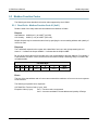
5-pin Connector
Pin
Description
Vin+
9-28VDC (+) power supply input.
Caution: DO NOT EXCEED MAXIMUM POWER SUPPLY VOLTAGE.
Vin-
Power supply (-) input. (Internally connected to the Gnd terminal)
Gnd
Ground connection for 5VDC output
Data
1-Wire bus data connection for digital temperature and humidity sensors.
+5V Out
This output voltage is used to provide power for the 1-wire digital
temperature/humidity sensors.
2.3.3 System Start Up
At power-up, the green Power LED should be illuminated. The X-600M requires 10 to 15 seconds for the
operating system to load before it becomes operational.
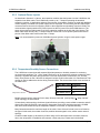
2.3.4 Expansion Module Connections
Expansion modules are connected to the X-600M with a 10-conductor ribbon cable. Normally the X600M and the expansion modules are mounted side by side as shown in the photo below. The ribbon
cable connectors have a polarization lug to ensure correct connections.
Page 14
Xytronix Research & Design, Inc.
X-600M Users Manual
Installation and Wiring
2.3.5 Optional Power Injector
As described in Section 2.3.2 above, the expansion modules draw their power from the X-600M thru the
expansion bus ribbon cable. The X-600M can provide up to 1.7 Amps for powering the attached
expansion modules. In applications where a large number of expansion modules are used and additional
current capacity is needed, a DC power injector can be employed. This accessory has two ribbon cable
connectors and a connector for supplying 9-28V to the expansion bus separately from the X-600M. The
communication signals pass-thru the power injector but the DC power from the X-600M does not. The
power injector thus provides power for all of the expansion modules to the left side of the injector. The
ribbon cable itself can only carry 1.7Amps maximum. Install one or more power injectors such that no
portion of the ribbon cable carries more than 1.7Amps
Note: It is recommended to power the X-600M and power injectors using the same power supply.
2.3.6 Temperature/Humidity Sensor Connections
The X-600M can communicate with external digital temperature or humidity sensors for monitoring
environmental conditions. The “1-Wire” data bus allows up to 32 temperature sensors to share the same
terminals. Together with power and ground the 1-wire bus requires three connections (+5V, Ground,
Data). Every sensor on the 1-Wire bus is assigned a unique serial number when it is manufactured. That
number is used to address the device during communication. The sensors have three wires as shown in
the table below.
Sensor Wire Color Connection
Temperature Sensor
Red
5V Out
Black
Gnd
Blue, White, Yellow
Data
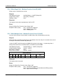
Multiple sensors can be connected in two ways: Directly connected (star topology) or “daisy chained”
(linear topology) as shown below.
A linear (daisy chain) topology minimizes signal reflections, providing a more reliable connection and will
allow longer cable length than a star topology. Appropriate strain relief should be used at the X-600M
and other connections that may be subjected to vibration, movement, or repeated handling.
Many factors determine the maximum length of the cable. Some of these include, but are not limited to
the type of cable used, the number of sensors, ambient electromagnetic noise, and/or sensor network
topology.
Combined cable lengths (to all sensors) of 600 ft using Cat 5e cable have been successful; however,
due to the uniqueness of installation environments, results may vary. Please test in the desired
Xytronix Research & Design, Inc.
Page 15
Installation and Wiring
X-600M Users Manual
environment before making a permanent installation.
Star vs Linear Connections
The following are general recommendations that will maximize sensor runs and minimize
problems:
•
Avoid sensor runs adjacent to industrial equipment power cables. These cables can have high
voltage spikes that may induce noise on the sensor signals. Similarly, avoid running sensor
cables near any radio transmission antennas or coaxial feed-lines.
•
Protect any exposed electrical connections with appropriate weather protection.
•
Do not “hot plug” wall mount Temperature/Humidity sensors into a powered X-600M. Use the
internal jumpers in the Temperature/Humidity module to enable/disable the sensors as needed
during discovery and test.
•
Due to the broad range of applications and environments where the X-600M may be employed,
successful installations of long sensor runs may vary significantly.
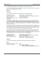
Cat 5 and Cat 5e network cable have proven to be an effective and low-cost solution for long runs. Other
cable types can be used, but cable capacitance may limit the length. The illustration below shows the
recommended connections using Cat 5 network cable. Connect all unused conductors to ground.
Figure 1: 1-Wire Connections With CAT-5 Cable
Page 16
Xytronix Research & Design, Inc.
X-600M Users Manual
Installation and Wiring
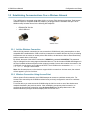
2.3.7 Network Connection
Connect the Ethernet port to a 10 Base-T or 10/100 Base-T Ethernet connection. Typically an Ethernet
hub, switch, or router. For configuration, the X-600M may be temporarily connected directly to the
Ethernet port on a computer by using a standard Ethernet cable (crossover cable not necessary).
The X-600M can be used on a wireless network by making a connection through an Ethernet bridge or a
wireless router. The X-600M also works with an 802.11b/g/n USB wireless adapter (see section 3.2 for
supported wireless USB adapters).
Note: The wireless Ethernet bridge or router must be properly configured for the wireless network. Refer
to the installation instructions for the wireless device.
USB WiFi Adapter
2.3.8 External USB Flash Drive
An external USB flash memory drive can be plugged into the USB socket for data logging and other
applications. The USB flash memory drive must be formatted with a FAT32 file system architecture.
Drives with NTFS (New Technology File System) or EXT2-4 will NOT work. The X-600M only
accesses the 1st primary file partition. Be aware that many low cost consumer and commercial USB
flash drives employ MLC (Multi Level Cell) technology and are designed for high capacity, 0ºC to
70ºC applications. If your application requires industrial temperature (-40ºC to 65.5ºC) operation or
increased reliability, consider selecting a USB Flash Drive with industrial temperature specifications.
Look for an industrial flash drive with SLC (Single Level Cell) components and a 5-year warranty.
SLC components have the highest endurance and longest life cycles. See Optional Accessories.
The System > Overview menu shows the capacity and amount of memory currently used on the
external USB Flash Drive. Normally the external USB Flash Drive can be unplugged at any time.
However, since data logs are buffered before written to the Flash Drive, when the Flash Drive is
unplugged there is risk of loosing the most recent data log. If this is of concern, click the Eject
button on the System > Overview menu to force all buffered data logs to be written and any open
files to be closed before unplugging the USB Flash Drive.
Xytronix Research & Design, Inc.
Page 17
Configuration and Setup
X-600M Users Manual
Section 3: Configuration and Setup
3.1 Establishing Communications Over Wired Network
In order to configure the X-600M using its built-in web browser, the X-600M and computer must be
addressed on the same network. This can be done by one of two methods:
Method 1 – Use NetBIOS/mDNS to access the X-600M after it has obtained an ip address using DHCP.
-ORMethod 2 – Temporarily change the IP address of a connected computer to the match the default IP
address used by the X-600M.
Note: If multiple ControlByWeb products are used on the same network, install one at a time and set the
IP address and NetBIOS/mDNS name (or disable NetBIOS/mDNS) of each unit before connecting the
next unit to the network. This avoids having multiple devices on the network with the same factory
default IP address at the same time. If this approach is used, be sure to clear the arp cache after
disconnecting each unit (arp -d) and clear the NetBIOS/mDNS cache (“nbstat -RR” on Windows “sudo
killall -HUP mDNSResponder” on OS X Mountain Lion).
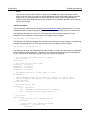
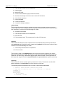
3.1.1 Method 1: Use DHCP and NetBios
This option can be used on a new X-600M. For this to work, the X-600M needs to be installed on a
network which has a DHCP server. Most routers have a DHCP server installed and enabled by default.
This method works as follows:
1. Connect X-600M to local network using an Ethernet Cable.
2. After the network is connected, apply power (See wiring diagram top-right).
3. Wait about 15 seconds and enter http://x600.local/setup.html into the address bar of
your browser.
4. Enter the username (admin) and password (webrelay).
5. Click on the Network setup pages and change the IP address to the desired setting.
Once connected, make sure to go to the Network > Advanced Network > NetBIOS / mDNS settings tab
and change the Local Host Name from x600 to another name, especially if you have multiple X-600M
units to configure. Also, you will need to clear the NetBIOS or mDNS cache before configuring another
unit using this method. In Windows, this can be achieved by opening a command prompt as an
administrator and typing “nbtstat -RR”. In MAC OS X, stale mDNS entries will be flushed after a
failed communication attempt after about 15 seconds.
If you are not using a router (no DHCP server), or are using a direct connection between the X-600M
and your computer you must use Method 2 described below.
Note: After power-up the X-600M attempts to obtain an IP address from your DHCP server up to three
times in a nine second period. If all attempts fail, the IP address reverts to 192.168.1.2 and you must
use Method 2 as described below.
Page 18
Xytronix Research & Design, Inc.
X-600M Users Manual
Configuration and Setup
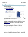
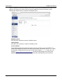
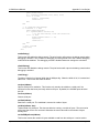
3.1.2 Method 2: Assign a Temporary IP Address to the Configuration Computer
If the first option above is not used, you can use this option to communicate with the X-600M. By default,
the X-600M comes from the factory with an IP address of 192.168.1.2. Communication with the X-600M
may be established by assigning an IP address to the configuration computer such that it is on the same
network as the X-600M (for example, the configuration computer could be assigned to 192.168.1.50)
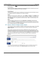
The following example is for those running the Windows-8 operating system:
1. Apply Power, wait 15 seconds for the X-600M to become operational, and then connect the Ethernet
cable.
2. Open the Windows 8 start screen
3. Type “Control Panel” and press enter (the search box opens automatically when you begin typing).
4. Click or touch View network status and tasks.
Xytronix Research & Design, Inc.
Page 19
Configuration and Setup
X-600M Users Manual
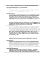
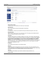
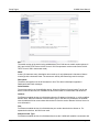
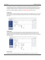
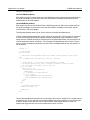
5. Click or touch Change adapter settings
6. Your machine may have more than one Internet connection shown. Right click on the adapter for
your connection to the internet. A drop down box will appear, choose Properties to view/edit the
settings for this internet connection.
Page 20
Xytronix Research & Design, Inc.
X-600M Users Manual
Configuration and Setup
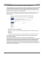
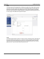
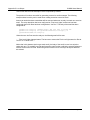
7. Select Internet Protocol Version 4 (TCP/IPV4) and then click the Properties button.
8. If “Use the following IP address” is already selected, the computer has been setup with a static IP
address. Record these values so that the current IP address of the computer can be restored once the IP
address of the X-600M has been successfully changed.
Xytronix Research & Design, Inc.
Page 21
Configuration and Setup
X-600M Users Manual
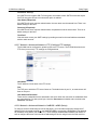
Select the radio button labeled "Use the following IP address" and type in the IP address:
192.168.1.50
Type in the subnet mask:
255.255.255.0
No need to change the default gateway field. Click OK to accept the new settings.
9. Open the setup pages by entering the following URL in the address bar of a web browser:
http://{ipaddress}/setup.html
(For example: http://192.168.1.2/setup.html)
Note: If the setup pages are not accessible, verify that the X-600M is powered on and that the LINK light
is illuminated. Check all network connections and settings.
Another way to check communications is to ping the X-600M from the command prompt by typing:
ping [ipaddress] (e.g. ping 192.168.1.2)
Page 22
Xytronix Research & Design, Inc.
X-600M Users Manual
Configuration and Setup
3.2 Establishing Communications Over a Wireless Network
The X-600M can be accessed using either Ad-Hoc or Access Point wireless connections. Both access
methods requires a compatible USB WiFi adapter to be plugged into the X-600M's USB port. The X600M currently includes drivers for the following WiFi adapters:
•
•
EDIMAX EW-7811Un
ASUS USB-N10
ASUS USB-N10
EDImax Nano
3.2.1 Ad-Hoc Wireless Connection
With an Ad-Hoc network connection you can access the X-600M directly using a smart phone or other
compatible WiFi-enabled device. With an Ad-Hoc connection the network does not rely on a pre-existing
infrastructure such as routers or access points. With Ad-Hoc, the devices are free to associate with any
Ad-Hoc network device in link range.
By default, the name of the Ad-Hoc connection is X600M with password 0123456789. This password
may be changed from the setup pages as described later on. The device name X600M should appear in
the list of available wireless networks on the computer or tablet. Once a device makes a connection, the
X-600M will give the device an IP address via DHCP. The X-600M can be accessed at x600.local or
192.168.3.1 through a web browser.
Note: Not all smart phones or other devices support Ad-Hoc connections. In these cases, the network
will not appear in your list of choices.
3.2.2 Wireless Connection Using Access-Point
With an Access Point connection, the X-600M attempts to connect to a wireless access point. For
Access Point connectivity the X-600M must have been previously configured to connect to a wireless
access point.
For a new device you must access the X-600M using the Ad-Hoc mode or one of the wired access
methods described in the previous section. After establishing a temporary wired connection, to
configure an Access Point connection, select ▼Access Point from the drop-down menu in the
Network>Wireless (Configure wireless adapter) tab. See Section 4.2.2
Xytronix Research & Design, Inc.
Page 23
Configuration and Setup
X-600M Users Manual
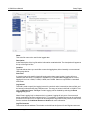
3.3 Configuration and Setup Access
The X-600M is configured using a web browser. To access the setup pages, enter the following URL in
the address bar of a web browser:
http://{ipaddress}/setup.html
For example, using the default IP address, enter:
http://192.168.1.2/setup.html
If you are using the “config via DHCP” method described in Method 1 above enter:
http://X600.local/setup.html
Before editing the setup pages, you will need to enter a username and password. The default username
is admin and the default password is webrelay (password is case sensitive).
The left side of the configuration and setup pages have click-able menu tabs (above right) which provide
access to specific configuration and setup settings. With all of the setup pages, if no activity is detected
for 30-minutes the user is automatically logged out. If this happens, your browser page should
automatically be redirected to the login page. To restore the setup session again, enter the setup URL
(http://{ipaddress}/setup.html) into address bar of your web browser (if not already there) and reenter the
username/password. The control and display (non-setup) pages are called dashboard pages
(http://192.168.1.2/index.html) and are not monitored for inactivity. The dashboard pages can remain
open indefinitely.
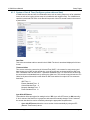
The setup pages are divided into seven setup sections: System, Network, Devices, I/O,
Control/Logic, Logging, and Edit Dashboards. The eighth section, View Dashboards, is for viewing
and testing the dashboards. Each of the setup tabs is described in the following sections.
Note: The X-600M setup pages require a modern web browser with javascript enabled to function
correctly. These browsers include Internet Explorer 9 and above, and latest versions of Chrome, Firefox
and Safari. If configuring the X-600M on a mobile device make sure to use a web browser that supports
pop-up windows. Once the X-600M is configured, the Dashboards are viewable by all modern web
browsers on mobile devices.
3.4 Basic Setup Strategy
The X-600M is configured and programmed using its built-in web pages. The configuration can be quick
and simple for small systems or require more design and thought for complex systems. The X-600M is
both easy to use and yet still has the resources to handle complex applications. You can start with the
Page 24
Xytronix Research & Design, Inc.
X-600M Users Manual
Configuration and Setup
built-in logic functions and dashboards and progress to scripts and custom web pages as needed.
The configuration and setup consists of the following basic steps:
Step 1. Configure the network parameters.
Begin by setting the IP address and making the associated network settings. These settings are
made under the Network tab. The goal is to get the X-600M accessible on your network. Test
your settings by accessing the X-600M with your web browser.
Step 2. Add new devices.
The X-600M has no built-in relays or inputs. Instead, it functions as a powerful master controller
for other ControlByWeb modules. The X-600M can control up to 128 ControlByWeb devices.
These devices can be physically located anywhere in the world with internet access. In addition,
the X-600M has a ribbon cable expansion bus connector which allows a family of add-on
modules to be connected directly to the X-600M. Expansion modules are available with relay,
digital input, thermocouple and other industrial inputs and outputs. Before these devices can be
controlled or accessed they must be entered into the X-600M's database. This is done with the
Devices tab. For modules on the IP network you either automatically scan for devices on the
same subnet or manually enter the IP address. With expansion modules you either automatically
scan for devices or manually enter the serial number of the module. Normally you enter a user
friendly name and description for each device. For example you might name a WebRelay-Quad
“PanelBoardA” with a description of “Warehouse Lights”. When complete, the Devices menu tab
will show a list of all the devices (modules) you wish to monitor or control.
Step 3. Add I/O (Inputs & Outputs).
Devices have inputs and outputs. Before the inputs and outputs can be monitored or controlled
they must be entered into the X-600M's database. This is done with the I/O tab. You add I/O
objects to the I/O list one by one. To add an I/O, click on the I/O tab in the left hand menu to see
a list of all available I/O types based on the devices that have already been configured in step 2.
Select the I/O type to add and click Add New I/O to add an instance of that I/O. A popup window
will then appear where the I/O can be specified and a name and description can be assigned to
the I/O. Normally you enter a user friendly name and description for each I/O object. For
example you might name one relay of a WebRelay-Quad “circuitA1” with a description of
“Loading Dock Lights”. When complete, the I/O menu tab will show a list of all the I/O objects
you wish to monitor or control.
Step 4. Add Conditional Events
Conditional Events occur when certain criteria are met, such as a temperature reaching a certain
value. The conditions which generate an event can be both simple and complex. If you are
simply monitoring inputs and controlling outputs with a web page you can skip this step.
Step 5. Add Actions
Conditional Events in turn trigger Actions. An Action can include sending an Email, turning a
relay on or off, or initiating a data log. Of importance an Event can trigger more than one Action.
For example, a Conditional Event could occur when the temperature exceeds a certain value,
the Event could trigger two Actions. One Action could turn a relay on to illuminate an alarm light
and a second Action could send an Email alert. The scheme of keeping Events and Actions
separate and distinct allows for complex conditions and reporting needed by many real world
applications. If you are simply monitoring inputs and controlling outputs with a web page you can
skip this step.
Step 5. Create/Edit a Dashboard
A dashboard is a web page that users can access to view and control I/O. You customize
dashboards by placing widgets, panels and components. The widgets and panels can be
customized and labeled. For example, a widget might be labeled “Upper floor”. Within a widget
Xytronix Research & Design, Inc.
Page 25
Configuration and Setup
X-600M Users Manual
the user places components. A component can be an on/off button labeled “Suite #1 lights”, a
temperature readout or other resources. Components are available for control, status, logging
and graphing. Components can be buttons, sliders, display boxes, etc.
Step 6. View Dashboards
The View Dashboards menu tab presents a display similar to what users will normally see
when accessing the X-600M. Use this page to test and debug the dashboards, panels, widgets
and components in real time.
3.5 Setup Example
The Quick Start Demo
After making the power and Ethernet connections, the X-600M can automatically scan for the presence
of any ControlByWeb Ethernet devices (on the same sub-net) and also for of any expansion modules
connected to the X-600M via the ribbon cable connector. It can also automatically create a dashboard
web page and populate it with all of the resources (components) supported by the Ethernet devices and
expansion modules.
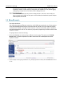
To quickly add a device do the following:
1. Click on the Devices menu tab to pull up the Devices Overview page. Then click on the Find New
Devices button to scan the expansion bus and the local network for ControlByWeb devices and
expansion modules.
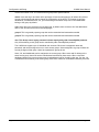
2. In this example we are going to add an X-11s (2 Relay expansion module.) Click the Add button for the
X-11s.
Page 26
Xytronix Research & Design, Inc.
X-600M Users Manual
Configuration and Setup
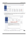
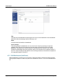
3. In the Select column, click the check boxes of the I/O components you would like to configure and select
the Create Device Widget check box (This will display the status of the I/O on the Dashboard). Click
Add Checked I/O to submit these changes.
4. Click Commit Changes - Once clicked, the X-600M begins to monitor the newly added device. Note:
You can make changes to multiple pages before you need to Commit Changes.
Xytronix Research & Design, Inc.
Page 27
Configuration and Setup
X-600M Users Manual
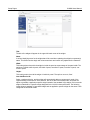
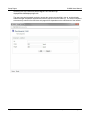
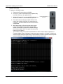
5. On the main menu, click the View Dashboards menu tab. The View Dashboards page shows a display
similar to what users will see when accessing the X-600M's control page. Use this page to test and
debug the dashboards, panels, widgets and components in real time. A pull-down menu allows access to
other dashboards. Within minutes you can experience the power and flexibility of the dashboard's user
interface and experiment/test the buttons, sliders, and data entry boxes to meet the needs of your
specific application.
3.6 Making Changes
The settings for the X-600M are maintained in an internal database. As you make changes you must
submit those changes (the Submit button on the bottom of each page) which stores those settings into a
temporary database in RAM. Whenever you make a change to a setting, the Commit Changes link at
the top, right-hand corner of the page will be highlighted. When you have finished making changes, click
Commit Changes to save your work permanently and to cause the new settings to become functional.
You can submit multiple setup pages before you commit changes. If you click on Abandon Changes all
changes in the temporary database will be deleted (all changes made since the last time changes were
committed)
You can click the Commit Changes button after making every change; however, it takes 5-10 seconds
Page 28
Xytronix Research & Design, Inc.
X-600M Users Manual
Configuration and Setup
to save the settings to the database and this can soon become tedious. You will find it more efficient to
make all of the changes, and then click the Commit Changes button to save all of the changes to the
database at once. New or edited settings will not become functional until the Commit Changes button is
pressed.
If you click the View Dashboards menu tab and discover that the components are blank or don't work,
the problem could be that you have not committed your changes to the database. If this occurs you have
not lost your settings, simply go back to one of the configuration tabs and click the Commit Changes
button.
3.7 Dashboard Access - Users and Access Groups
The X-600M has flexible and advanced access control features needed for real-world applications.
Access to the setup pages described in the sections below always requires administrator privilege with a
username and password. User access to the Dashboards is configurable. The System>Overview
setup page has a global setting for Dashboard and I/O Password Protection. See Section 4.1
This setting can be used to enable or disable password access to the Dashboards and I/O. The default
setting is Disabled. Check the Enabled setting if you wish to require users to enter a username and
password to access the Dashboards. If password protection is enabled, Access Groups and other
menus used to manage password access are displayed in subsequent menus. If password protection is
disabled, Access Groups and other menus used to manage password access are not displayed in
subsequent menus. This global setting helps keep the setup pages simple and easy to use for those
who do not need password protection.
3.7.1 Access Groups
The X-600M supports five different access groups. All groups can be configured as a Read Only group
or Read Writable group. Read Only groups allow monitoring of I/O only. Read Writable groups allow
Xytronix Research & Design, Inc.
Page 29
Configuration and Setup
X-600M Users Manual
monitor and control of I/O. The admin and cbw groups have special features.
admin: Users who log-in and have admin privileges will see the setup page(s), all others will not have
access to these pages and cannot change the configuration of the device. If you want to configure
dashboards, connected devices, etc, you must belong to the admin Group. All I/O and dashboards
belong to this group by default.
user: Users who log-in and have user privileges will, by default, have access to all of the dashboards
and I/O, but will not have access to the setup pages.
group1: This is a general purpose group that can be customized and renamed as needed.
group2: This is a general purpose group that can be customized and renamed as needed.
cbw: This Group uses a legacy password scheme employed by older ControlByWeb products.
Only I/O that belong to this group can be controlled by older ControlByWeb products.
The X-600M can support up to 30 individual user accounts. Each user is assigned a name and
password, and can be assigned to one or more access groups. Users assigned to a group will have the
access privileges of that group. Users have passwords, groups do not.
Users, I/O, and dashboards can be assigned to an access group. When users and I/O belong to the
same access group, those I/O can be controlled and monitored by those users. When a user and
dashboard belong to the same access group, that dashboard can be viewed by that user. If a user, I/O,
or dashboard do not belong to the same group, those items cannot be controlled/monitored by that user.
Page 30
Xytronix Research & Design, Inc.
X-600M Users Manual
Setup Pages
Section 4: Setup Pages
The left side of the configuration and setup pages have click-able tabs which provide access to specific
configuration and setup settings. Each of the tabs are explained the following sections.
4.1 System Tab
The Overview page displays basic information about the X-600M module and its operating system. Note
the Serial Number is the same as the MAC address for the wired Ethernet adapter. The Up Time is the
elapsed time since the last system reset. The Internal Temperature is measured with an internal digital
temperature sensor. Note: The internal temperature is normally higher than the ambient temperature.
External Storage shows the capacity and amount of memory used on the external USB Flash Drive.
Normally the external USB Flash Drive can be unplugged at any time. However, since data logs are
buffered before written to the Flash Drive, when the Flash Drive is unplugged there is risk of loosing the
most recent data log. If this is of concern, click the Eject button to force all buffered data logs to be
written and any open files to be closed before unplugging the USB Flash Drive.
The Dashboard and I/O Password Protection setting can be used to enable or disable password access
for all users. The default setting is Disabled. Check the Enabled setting if you wish to require all users to
enter a password to access the dashboards. If password protection is enabled, Access Groups and
other menus needed to manage password access are displayed in subsequent menus. If password
protection is disabled, Access Groups and other menus needed to manage password access are not
displayed in subsequent menus. Note: If password protection is disabled, access to the X-600M's setup
pages still require an administrator password.
To access other system settings, click System on the menu bar on the left side of the setup screen.
Several subsections will appear.
Xytronix Research & Design, Inc.
Page 31
Setup Pages
X-600M Users Manual
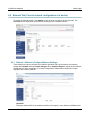
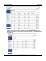
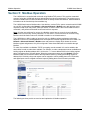
4.1.1 System > Access Groups (Edit access groups)
This menu and its tab are only displayed if Dashboard Password Protection in the System>Overview page
is set to Enabled. Users, I/O, and dashboards are assigned to one or more Access Groups. Users can only
access I/O and dashboards that belong to the same group that they do. Only users that belong to the admin
Access Group are allowed to configure the X-600M settings. Only I/O that belong to the CBW Access Group
can be controlled remotely by other ControlByWeb devices. All other Access Groups are generic and can be
used for any purpose.
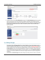
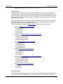
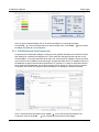
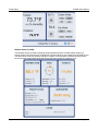
The following example illustrates the use of access groups.
The image above depicts a scenario where 3 access groups are being used. There are 6 users
configured on the X-600M and 7 relays. To determine if a user has access to one or more of the relays
examine the access group. (depicted as a circle). The 3 users in the Admin access group, Mark, John,
and Sara, have access to any relay also found in the Admin group: relay 1, relay 2, relay 3, and relay4.
The 3 users in the User access group, Jennifer, Ryan, and Mike, have access to any relay also found in
the User access group: relay 2, relay 4, relay 5, and relay 6. There are no X-600M users in the CBW
access group. The CBW access group is a special group. All other ControlByWeb products that can
Page 32
Xytronix Research & Design, Inc.
X-600M Users Manual
Setup Pages
control remote relays belong to the CBW group. This means in this example that a ControlByWeb
device that is configured to control a remote relay on the X-600M, can only control relay 3, relay 4, relay
6, or relay 7.
Another thing to mention is that each access group has a read/write setting. In the previous example,
each group was configured for read and write, meaning that the I/O belonging to those access groups
could be monitored and controlled by the users in those same access groups. If, on the other hand, the
User access group was configured as a read only access group, then Jennifer, Ryan and Mike would
only be able to monitor relay 2, relay 4, relay 5, and relay 6. No control would be available.
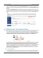
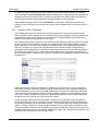
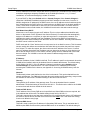
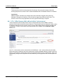
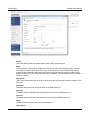
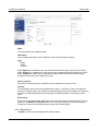
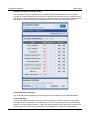
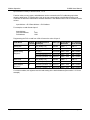
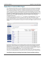
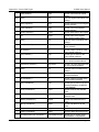
4.1.2 System > User Accounts (Add, edit, and delete user accounts)
The X-600M can support up to 250 individual User Accounts. Each user account is shown in a separate line.
Click Add New User to create a new user account. The settings and passwords for each user account can
be changed by clicking the Edit icons.
Each user is assigned a password and one or more Access Groups (enable Dashboard and I/O
Password Protection under the System > Overview menu tab in order to view and change Access
Group settings). Users who are assigned to an access group will have access to any I/O and
dashboards that also belong to that particular access group. Users have passwords, Groups do not.
Note: Email alerts can be sent to users (or groups) - These users can be set up to receive email alerts
only while having no access to the dashboards and I/O.
Xytronix Research & Design, Inc.
Page 33
Setup Pages
X-600M Users Manual
Full Name:
This is a simple description of the user account for documentation purposes.
Email:
The email address for this user.
Username:
This is the user name for this user account (used for logging in).
Password:
The Password for a specific user can be modified by entering a new password here. Passwords that
are 8 characters or longer (up to 20 characters can be entered in this field) with both alphabetic and
numeric characters are recommended. For security purposes, the password will not be displayed
when entered.
Note: The default user name required for accessing the setup pages is admin (all lowercase). The
default Setup Password is webrelay(all lowercase).
Confirm Password:
When the password is changed, it must be entered twice for verification. If the password is not
entered identically in both fields, the password will not be changed.
Access Groups:
This setting is only displayed if Dashboard Password Protection in the System>Overview page is
set to Enabled. Access groups have a descriptive name as well as a member title used to describe
the members of the group. Access groups can also be declared Read Only or Read Writable. Users
in groups that are read only will be able to monitor I/O in the same group, but not control them.
Page 34
Xytronix Research & Design, Inc.
X-600M Users Manual
Setup Pages
4.1.3 System > Date & Time (Configure system date and time)
X-600M uses the date and time for scheduled events, such as turning relays on or off at scheduled
times, as well as for logging (a time stamp is included with each logged event). The X-600M has a
capacitor backed real-time-clock circuit that will keep track of time for several weeks in the event of
a power failure.
Date/Time:
This is the current date and time stored in the X-600M. The time is stored and displayed in 24-hour
format.
Timezone Offset:
Time servers return the current time in Universal Time (GMT). It is common for many servers and
data loggers to use GMT as their official time, even when they are not located within the GMT time
zone. The default value for this field is -7 (Mountain Standard Time). For convenience, the time can
be converted to local standard time by entering the offset here. This manual cannot include the UTC
Offset for all parts of the world, but the offset for GMT time and the four major US Time zones are
listed here:
GMT Time: 0
Eastern Standard Time: -5
Central Standard Time: -6
Mountain Standard Time: -7
Pacific Standard Time: -8
Sync With NTP Server:
This selection offers two options for setting the time: YES (sync with NTP server) or NO (manually)
If Yes is selected, the Date/Time is grayed out and cannot be manually changed. If No is selected,
the current date and time can be entered by selecting the appropriate drop-down box.
•
Sync with NTP server allows the user to set the clock automatically by using an NTP
(Network Time Protocol) server.
Xytronix Research & Design, Inc.
Page 35
Setup Pages
X-600M Users Manual
•
Manually requires the user to enter the time and date
NTP Host Name:
This field is used to specify the name or IP address of the NTP server. If a name is specified, a
working DNS server address must be entered into the Network > Ethernet settings page. If the IP
address is specified, it should be entered in the following format aaa.bbb.ccc.ddd where each of the
letters represents a number between 0 and 255. This field can be up to 60 characters. There is no
default value for this field.
Many NTP Internet servers are available. In addition, many desktop computers can function as an
NTP server (both Mac and PC). If a desktop computer is used, firewall settings may need to be
adjusted to allow for NTP communications on port 123.
Public NTP servers can be found at www.pool.ntp.org. Some of these are listed below:
US Servers (http://www.pool.ntp.org/zone/us):
0.us.pool.ntp.org
1.us.pool.ntp.org
2.us.pool.ntp.org
3.us.pool.ntp.org
North America (http://www.pool.ntp.org/zone/north-america):
0.north-america.pool.ntp.org
1.north-america.pool.ntp.org
2.north-america.pool.ntp.org
3.north-america.pool.ntp.org
Europe (http://www.pool.ntp.org/zone/europe):
0.europe.pool.ntp.org
1.europe.pool.ntp.org
2.europe.pool.ntp.org
3.europe.pool.ntp.org
Australia (http://www.pool.ntp.org/zone/au):
0.au.pool.ntp.org
1.au.pool.ntp.org
2.au.pool.ntp.org
3.au.pool.ntp.org
South America (http://www.pool.ntp.org/zone/south-america):
0.south-america.pool.ntp.org
1.south-america.pool.ntp.org
2.south-america.pool.ntp.org
3.south-america.pool.ntp.org
Africa (http://www.pool.ntp.org/zone/africa):
1.africa.pool.ntp.org
1.pool.ntp.org
3.pool.ntp.org
NTP Sync Interval:
This setting allows the user to specify how often the time on the X-600M will be synchronized with
the time server. When the Submit button on this page is pressed, the X-600M will immediately
Page 36
Xytronix Research & Design, Inc.
X-600M Users Manual
Setup Pages
synchronize with the time server. The next NTP sync will occur X minutes after the time this
configuration page was submitted (where X = NTP Sync Interval in minutes). The default value for
this field is set to 1440 minutes.
Daylight Savings:
In many parts of the United States and in some other countries, the time is shifted forward by one
hour during the summer months. This is an effort to conserve energy by making the daylight last
longer into the evening hours. If this option is set to Enabled, the time on X-600M will automatically
be shifted forward by one hour between the DST Start date and time and the DST End date and
time. The default setting is Enabled.
Note: Enabling the daylight savings time adjustment, scheduled events will be adjusted for the new
time, possibly leading to duplicate events. Logged data uses a GMT time stamp that does not
account take into effect daylight savings. When viewing the logged data, these timestamps are
adjusted to the timezone configured for the X-600M and could also present duplicate logs around
daylight savings time changes.
DST Start:
This is the date that daylight savings will start. At this date and time, the time will be shifted forward
by one hour (i.e. the time will jump from 12:02 AM [00:02] to 1:02 AM [01:02]). By default this is set
to the 2nd Sunday in March which is the date used in the United States.
DST End:
This is the date that daylight savings will end. On this date and time, the time will be shifted
backward by one hour (i.e. time will jump from 12:02 AM [00:02] to 11:02 PM [23:02] the day before).
By default this is set to the 1st Sunday in November which is the date used in the U.S.
4.1.4 System > Backup/Restore (Backup and Restore Settings)
The Network settings, Conditional Events, Actions, Scripts, Registers and other settings for the X-600M
are stored in a database. The entire database can be exported or imported as a file. The
Backup/Restore page is used for archiving the settings and can also be used to move the settings from
one module to another.
To export the database, click the Export button. A window pops up in the browser where you can name
and save the file on your computer. To import a database, click Choose File. A File-Upload window will
pop up in your browser. Navigate to the desired file and click Open. Next, click Import to import the file.
The import feature has two additional options. The first, Use Default Network Settings, allows a
settings file to be imported with the network settings forced to their default values. This option is useful
Xytronix Research & Design, Inc.
Page 37
Setup Pages
X-600M Users Manual
for setting up multiple units that will function similarly, but will require different network configurations.
The second option, Use Default Password, allows a settings file to be imported with the username and
password forced to their default values. This option is useful when the settings need to be loaded to a
device and the username and/or password for the administrator have been forgotten.
When importing settings, they must be Committed before taking effect. Remember to backup your
settings to a file in case the unit ever needs to be reset to factory defaults and you wish to preserve the
settings.
4.1.5 System > SSL Certificates
The X-600M supports secure connectivity to the internal web server using a Secure Sockets Layer
(SSL) certificate. An SSL certificate works to establish a secured and encrypted connection between the
X-600M and the web browser. With this secured connection, all data passed back and forth to the X600M will be encrypted and protected from interception.
SSL certificates have three components. The Certificate Signing Request (CSR), the public key, and the
private key. When a new certificate is created on the X-600M, it will automatically generate all three of
these components. The CSR is used to allow a Certificate Authority (CA) to digitally sign and create a
public key. This public key will be sent to web browsers that access the X-600M. The private key is
generated by the X-600M when the certificate is made and is intended to never be accessed outside of
the X-600M. The private key will be used to decrypt data that has been encrypted by the public key in
the remote web browser. Conversely, the public key is needed to decrypt data the X-600M encrypts with
the private key.
When a web browser initiates the handshake to establish a secure connection, it tries to validate the
authenticity of the SSL certificate. Primarily, it looks to ensure the name on the certificate matches the
domain name used to connect with the X-600M. Additionally, it will ensure the certificate is valid for the
current date and time and that the certificate has been digitally signed by a trusted Certificate Authority
(CA). If any of these conditions are not met, the web browser will show the user a warning stating that
the web server may not be secure or that it cannot be verified.
An SSL certificate needs to be either self-signed or signed by a CA. Self-signed SSL certificates will
cause the web browser to issue a warning to the user unless the self-signed certificate is added to the
list of trusted certificates kept by the operating system. SSL certificates signed by a trusted CA (such as
DigiCert, VeriSign, Comodo, etc.) will not show a warning to the user and is what you will find on many
commercial websites. However, both certificate signing options will behave the same in how they secure
the data being transferred across the network. Additionally, multiple SSL certificates can be stored on the
X-600M, but only one may be in use at any given time.
Page 38
Xytronix Research & Design, Inc.
X-600M Users Manual
Setup Pages
4.1.5.1 Default Self-Signed SSL Certificate
The X-600M includes a default, self-signed SSL certificate uniquely generated and ready for use;
however, since this certificate is self-signed, you will see a warning page from your web-browser
stating the web server may be untrusted. This self-signed certificate has an expiration date of 200
years from the time it was generated and cannot be deleted. It is recommended to generate a new
self-signed SSL certificate.
4.1.5.2 Generating a New Certificate
Generating a new SSL certificate is not required for using HTTPS or securing the connection as a
default certificate is already available. However, generating a new SSL certificate will allow you to
use your organizations information as well as to get it signed by a CA. To start, click on the
Generate New Certificate button in the top right corner of the SSL Certificates screen. A pop-up will
open and allow you to fill in the information. Once the information has been filled out and submitted,
the X-600M will self-sign the certificate for immediate use. Instructions on having the certificate
signed by a CA are in the next section.
Certificate Name:
This is the name you will use to identify the certificate in the X-600M web interface. These
names must start with a letter, and contain only letters, numbers or the underscore character.
(e.g. testing_cert)
Country Code:
Two letter country code for the country where the X-600M will be used. (e.g. US)
State or Province Name:
Full name of the state or province the X-600M will be used in. (e.g. Utah)
City or Locality Name:
Full name of the city or locality the X-600M will be in. (e.g. Nibley)
Organization Name:
Full exact name of your organization with no abbreviations. (e.g. Xytronix Research & Design,
Inc.)
Organizational Unit Name:
Full organizational unit name. This is less important and can be something simple. (e.g. IT)
Common Name:
This is the domain name you will be accessing the X-600M from. If this does not match what is
placed in the browser when accessing the X-600M, your web browser will return a warning. (e.g.
X600.ControlByWeb.com)
No special work is needed in the X-600M to assign it a (sub)domain name. So long as an “A”
record exists in your DNS server to map the (sub)domain name to the X-600M IP address.
Email Address:
Allows you to place your e-mail address in the certificate information.
Encryption Strength:
This option allows you to specify the encryption strength of the data during the handshake phase
between the X-600M and the web browser. Some CA's have a restriction on this value. The
trend for the CA's is to have 2048-bit encryption strength. Certificates generated using 2048-bit
encryption can take up to six minutes to generate.
Xytronix Research & Design, Inc.
Page 39
Setup Pages
X-600M Users Manual
4.1.5.3 Signing Certificates with a Certificate Authority
Once a new certificate has been made, you can click on the Edit link to access the Certificate
Signing Request (CSR) as well as the signed certificate. Most CA's will have you copy and paste the
CSR from the X-600M web pages directly in to their web site. Once the CSR and the other
information requested by the CA have been submitted, the CA will generate and digitally sign a
certificate.
Once the signed certificate has been received, you will need to copy and paste the contents into the
Signed Certificate field of the respective certificate. If the CA has also included a CA bundle or
intermediate certificates, they can be appended to the end of the signed certificate in reverse order
with the root certificate being the last. For example, if the signed certificate has two intermediate
certificates, they would be placed in the Signed Certificate in the following order:
Signed Certificate
Intermediate 2
Intermediate 1
Root certificate
You will need to include all the starting and ending tags for each certificate.
4.1.5.4 Importing self-signed certificates
As an option, you may import the self-signed certificate in to the computers certificate store. This will
remove warnings about the certificate not being trusted. To do this, download the certificate from the
X-600M System > SSL Certificate pages for the certificate you would like to import. Once the
certificate has been downloaded, double-click the file and your computer will launch the wizard for
importing the certificate. Once it has been completed, restart your web browser. The certificate has
now been imported. This procedure will only remove warnings about the authenticity of the
certificate for the local computer.
4.1.6 System > Custom Web Pages
For most users and applications, the built-in control web pages with Dashboards, Panels, Widgets and
Components will be more than adequate; however, for users with more specific needs or where more
complex graphics are needed, the X-600M supports custom web pages. Custom web pages are built
with HTML, CSS, Javascript and PNG images files which are stored in the X-600M's file system. The
Custom Web Pages page displays a list of files currently stored in the file system.
Page 40
Xytronix Research & Design, Inc.
X-600M Users Manual
Setup Pages
Clicking on a file's name will cause the file to be immediately opened by your browser in a new tab. The
Edit button opens a simple, web-based text editor which allows you to edit the contents of HTML, CSS,
JS, and other similar ASCII files.
Clicking the New HTML File, New CSS File, or New JS File buttons will create a new file with the
respective file extension. You then use the web-based text editor to edit the new file(s).
Note: Custom web pages require programming skills with HTML, JavaScript and other web
programming languages - specific details of these programming languages are not covered in this
manual.
Xytronix Research & Design, Inc.
Page 41
Setup Pages
X-600M Users Manual
To download a file from the X-600M to your PC, click a file's Download button and then Save File. To
upload a file(s) from your PC to the X-600M, click Browse/Choose Files, select the file(s) to upload,
then click Upload. The new file(s) should appear in the file name list. To delete a file, click on its
respective Delete button. Only HTML, CSS, JS, and PNG files will be allowed for upload.
Custom web pages normally include dynamic content to provide both real time display and control. See
Appendix-H for specific details on how to add dynamic content to custom web pages.
4.1.7 System > System Log
The System Log menu tab displays the current contents of the system log file. The system log file is a
real-time list of system-level messages and events, as well as information about various user interaction
with the X-600M. The log file is useful for troubleshooting Email, NTP, and remote services connections.
It can also be used for security purposes. Read/writable I/O can be configured such that any activity for
that I/O will be logged to the system log, including user interaction. This can be useful for monitoring
what user changed what I/O at what time.
Page 42
Xytronix Research & Design, Inc.
X-600M Users Manual
Setup Pages
4.2 Network Tab (Current network configuration of a device)
To access the network settings, click Network on the menu bar (left side of the setup screen). The
Overview section displays the general status and settings of the network interface.
4.2.1 Network > Ethernet (Configure Ethernet Settings)
These settings are used to configure the X-600M for operation with a wired network. After entering
settings press Submit and then Commit Changes. When Commit Changes is clicked the new network
settings will take effect immediately. If you have changed the IP address the X-600M will no longer
respond to the current IP address.
Use DHCP:
This option allows DHCP to be enabled or disabled. If this option is set to Yes, the X-600M will wait
Xytronix Research & Design, Inc.
Page 43
Setup Pages
X-600M Users Manual
for an IP address from a DHCP server each time it is powered up. The default for this setting is Yes
to facilitate assigning a temporary IP address to the X-600M (See Section 3.1.1.) For most
installations, we recommend assigning it a static IP address.
If you set DHCP to Yes, press Submit and then Commit Changes. When Commit Changes is
clicked the X-600M will immediately request a new DHCP address from the server. Once the X600M is assigned an IP address by the DHCP server, the new IP address can be found through the
list of clients kept by the DHCP server (for most instances, the DHCP server is the local gateway or
router). Three DHCP requests will be sent out over a nine second window. If no DHCP server is
found within this nine second window, the X-600M will revert back to the static network settings.
Brief Notes About DHCP
All devices on an IP network require an IP address. This is a unique address that identifies each
device on the network. DHCP (Dynamic Host Control Protocol) is a mechanism that automatically
assigns an IP address to a computer (or other devices) when it is connected to a network. This
eliminates the need to manually enter the IP address. Devices using DHCP will request an ip
address and other network settings from the DHCP server on the network. On many small networks,
the DHCP server is built into the router.
DHCP works well for "client" devices such as computers, but is not ideal for servers. This is because
servers usually don't initiate communications with other devices, but rather they wait for a request
from "clients." To make this request, the client must know the IP address of the server. If a server
gets its IP address dynamically, the IP address may not always be the same so client devices may
not be able to find the server. For this reason, servers usually use an IP address that is fixed and
does not change. The X-600M is a server and manual IP address assignment is usually
recommended.
IP Address:
Enter the IP address for the X-600M in this field. The IP address is specific to the network where the
X-600M will be installed, and must be obtained from the network administrator. The default setting
for this field is 192.168.1.2. If the IP address is changed, remember to press Submit and then
Commit Changes as explained above. For more information on IP addresses and remotely
accessing the X-600M over the Internet, see Appendix C: Accessing X-600M Remotely Over the
Internet.
Netmask:
The Netmask (subnet mask) defines the size of the local network. This can be obtained from the
network administrator. For additional information about sub-netting and IP networking, many tutorials
are available on the Internet. The default setting for this field is 255.255.255.0.
Gateway:
This specifies the IP address of the gateway router. This can be obtained from the network
administrator. The default setting for this field is 192.168.1.1. This filed must be valid for the X-600M
to communicate with devices outside the local network.
Preferred DNS Server:
The IP address of the Primary DNS server is specified here. When DNS services are required, this
is the address that will be used. The default setting for this field is 192.168.1.1.
This field is required when any host name settings are fully qualified domain names. If IP addresses
are used for all host names, the DNS server will not be used. Note: This is the same DNS setting
found on the Wireless setup page.
Alternate DNS Server:
This field is used to specify the IP address of a Secondary DNS server. This is used when the X600M requires DNS services and the preferred DNS server is not available. The default setting for
Page 44
Xytronix Research & Design, Inc.
X-600M Users Manual
Setup Pages
this field is 192.168.1.1. Note: This is the same DNS settings found on the Wireless setup page.
IP Filter Range 1:
This option specifies a range of ip addresses on the subnet that should be allowed access to the X600M. By default all ip addresses on the subnet are allowed.
IP Filter Range 2:
This option specifies another range of ip addresses on the subnet that should be allowed access to
the X-600M. By default all ip addresses on the subnet are allowed.
Speed:
This option sets the speed of the Ethernet port - either 10 Mbps or 100 Mbps. The 100 Mbps option
offers faster communications but the amount of data to and from the X-600M is so small that users
will not likely notice much (if any) difference between that and 10 Mbps. The default setting for this
field is 100 Mbps.
Mode:
This option allows the Ethernet port to be set to Half Duplex or Full Duplex. Legacy Ethernet
operates in Half Duplex mode which means that devices can either send data or receive data, but
not both at the same time. Full Duplex means that devices can send and receive data at the same
time. The default setting for this field is Full Duplex.
4.2.2 Network > Wireless (Configure wireless adapter)
These settings are used to configure the X-600M for operation with a wireless network. The X-600M
supports both Ad-Hoc and Access Point connections. For wireless networking, a USB network
adapter is required.
With an Ad-Hoc connection users can access the X-600M directly using a smart phone or other
compatible WiFi-enabled devices. The network does not rely on a pre-existing infrastructure, such
as routers or access points. The devices are free to associate with any other ad-hoc network device
in link range. To configure an Ad-Hoc wireless network, select ▼Ad-Hoc from the drop-down menu
and enter a security key for the network. The security key must be exactly 10 hexadecimal
characters.
For an Access Point connection, the X-600M attempts to connect to a wireless access point. To
configure an Access Point connection, select ▼Access Point from the drop-down menu.
Xytronix Research & Design, Inc.
Page 45
Setup Pages
X-600M Users Manual
Network Name (SSID):
The SSID (Service Set Identifier) is the name of your access point.
Security Level:
Type of authentication used by the access point for connections.
Security Key:
If a password (i.e. security key) is required to access your wireless access point, enter it here.
Encryption Type:
Select the data encryption type from the drop-down menu. This setting must be identical with the
setting of wireless access point you wish to connect.
Use DHCP:
This option allows DHCP to be enabled or disabled. If this option is set to Yes, X-600M will attempt
to obtain an ip address from the access point each time it is powered. The default setting is No (this
is recommended for most installations). If you set DHCP to Yes, press Submit and then Commit
Changes. When Commit Changes is clicked the X-600 will immediately request a new DHCP
address from the server. Once X-600M is assigned an IP address by the DHCP, the new IP address
can be found through the list of clients kept by the DHCP server. For most instances, the DHCP
server is the local gateway or router.
IP Address:
The IP address must be unique to your wireless network.
Netmask:
The Netmask (subnet mask) defines the size of the local network. This can be obtained from the
network administrator. For additional information about sub-netting and IP networking, many tutorials
are available on the Internet. The default setting for this field is 255.255.255.0.
Gateway:
This specifies the IP address of your network's wireless access point (Router, etc.).
Preferred DNS:
Page 46
Xytronix Research & Design, Inc.
X-600M Users Manual
Setup Pages
The IP address of the Primary DNS server is specified here. When DNS services are required, this
is the address that will be used. Note: This is the same DNS setting found on the Ethernet setup
page.
Alternate DNS:
This field is used to specify the IP address of a secondary DNS server. This is used when X-600M
requires DNS services and the preferred DNS server is not available. Note: This is the same DNS
setting found on the Ethernet setup page.
4.2.3 Network > Advance Network Tab
To access the advanced network settings, click Network on the menu bar (left side of the setup screen)
and then click on the Advanced Network sub-menu bar.
4.2.3.1 Network > Advance Network > Web Server (Configure web server settings)
The HTTP port for the built-in web server can be changed with this menu.
HTTP Port :
The TCP port used for HTTP communications (web browser, xml, get commands) with X-600M is
specified here. The default setting for this field is 80, which is the standard HTTP port. It is
recommended that the port be left unchanged unless the user has an understanding of TCP/IP and
ports. For more information on TCP ports and IP addressing see Appendix C: Accessing X-600M
Remotely Over the Internet.
HTTPS Port :
The TCP port used for HTTPS communications (Hypertext Transfer Protocol Secure). The default
setting for this field is 443.
4.2.3.2 Network > Advanced Network > Modbus (Configure Modbus settings)
The X-600M can support Modbus/TCP as a slave device. Modbus is a messaging structure protocol
used in industrial manufacturing control and automation. It is an open protocol and offers interoperability
with software and devices from other manufacturers. With Modbus/TCP a Programmable Logic
Controller (PLC) or other Modbus master can control and monitor the X-600M and all of the devices
logically or physically attached to the X-600M. For more information on Modbus see Section 5: Modbus
Operation.
Xytronix Research & Design, Inc.
Page 47
Setup Pages
X-600M Users Manual
Modbus Enabled:
Modbus/TCP is enabled by selecting Yes in this field. The default setting for this field is No. (See
Section 5 Modbus Operation for more information on using X-600M on a Modbus network.)
Modbus Port:
This specifies the port used for Modbus/TCP communications with X-600M. By default this is set to
port 502 which is the standard Modbus port. It can be set within the range of 0 to 65535.
Endianness:
32-bit data is treated as two individual 16-bit words using IEEE 754 floating point format. Floating
point format is used for sensor, pulse counter, analog, and frequency data as well as for setting
output pulse duration. If the check box is set, the X-600M will use big-endian format, and the most
significant 16-bit word (big end) is sent first. If the box is cleared, then the X-600M will use littleendian format, and the least significant word (little end) is sent first. The default setting for this box is
little-endian. For example, in little-endian format, a 32-bit floating point number represented by '1234
ABCD' is sent as 'ABCD 1234'.
To make I/O available over Modbus TCP/IP, a mapping must be created. I/O can be added to the
three tables in order to make them available. For example, to make a temperature sensor available
as a holding register at Modbus address 0010, click on the “---” next to address 0010 in the Holding
Register table. A drop down list of I/O will appear. Select the temperature sensor and click Submit.
Now the Modbus master can access the value of the temperature sensor by reading Holding
Register 0010. Similarly relays and outputs can be mapped to coils by adding them to the Coils
table, and digital inputs can be mapped to discrete inputs by adding them to the Discrete Inputs
table.
4.2.3.3 Network > Advanced Network > Remote Services Server (Configure remote
services server)
This is a new feature available with the X-600M. This feature is sometimes referred to as “web services”
and allows other ControlByWeb devices to initiate a connection to the X-600M instead of the other way
around. Once connected, the X-600M can communicate with these devices just as if it had established
the connection. The benefit of this method of communication is that the remote ControlByWeb devices
can bypass firewalls without any extra configuration of the local network. This also eliminates the need
Page 48
Xytronix Research & Design, Inc.
X-600M Users Manual
Setup Pages
for port forwarding to be set up to allow access to the remote ControlByWeb device.
Other ControlByWeb devices can be configured to connect to the X-600M using remote services through
the Advanced Network tab on that device. The Server Name/IP Address should be that of the X-600M,
the Server Port should be the Remote Services port set on the X-600M, and the connection string
should be of the format “[00:0C:C8:00:00:00]:ControlByWeb,X-320”, where the mac address is the mac
address of the device attempting to connect to the X-600M.
Before the device can communicate with the X-600M, it needs to be added to the device list on the X600M under the Device menu page on the X-600M, and it's Ethernet Comm. Type must be set to
Remote Services.
Remote Services Server Setup Enabled:
Remote services server setup is enabled by selecting Yes in this field. The default setting for this
field is No.
Listen Port:
The X-600M will listen for incoming remote services messages on this port. The default is 8000.
4.2.3.4 Network > Advanced Network > Remote Services Client (Configure remote
services client settings)
The X-600M can act as a remote services client just like other ControlByWeb products.
Remote Services initiates the connection to the external web server (rather than the web server initiating
communications to the X-600M). This has two main benefits. First, the web server does not need to
know the IP address of the X-600M. This means that the X-600M can get its IP address dynamically
from a DHCP server, simplifying the installation. Second, since the connection from the X-600M is
outgoing, rather than incoming, the local router on the network where the X-600M resides does not need
to be configured for port forwarding. For more information about the Remote Services see Appendix E:
External Server and Remote Services.
Xytronix Research & Design, Inc.
Page 49
Setup Pages
X-600M Users Manual
Remote Services Enabled:
This option enables or disables Remote Services. If Yes is selected, Remote Services will be
enabled as soon as settings are committed. Once enabled, the X-600M will immediately attempt to
make a connection with the remote server (power cycle not required).
Once a connection is established, the connection will remain until it is disconnected by the remote
server. Proper connection with the remote server can be verified by viewing the system status log
file (see Appendix D: Log Files). The default setting for this field is No. Most users should leave this
setting at its default. (See Appendix E: External Server and Remote Services for more information.)
Host Name:
Specify the name or IP address of the Remote Services server here. If the IP address is specified,
enter it in this format aaa.bbb.ccc.ddd. For numbers that are less than 100, preceding zeros should
not be included (for example, enter 80 rather than 080). This field can be up to 40 characters long
and has no default setting.
Remote Port:
Enter the TCP port used for the Remote Services server. This can be set within the range of 065535. The default setting for this field is 8000.
Connection String:
This text is sent to the Remote Services server when the connection is established. This string
should include any information required by the server at connection. For example, it may include an
ID number, customer number, password, etc. The format is entirely dependent upon the server
requirements. This field can be up to 80 characters long. The default text is the connection string
used by other X-600M's that have been configured as remote services servers. The default text is
[<Serial Number>]:ControlByWeb,X-600M.
Connection Interval:
This field specifies the periodic interval in which the X-600M attempts to connect to the remote
server, or if the X-600M is already connected, it is the interval in which the X-600M sends the
connection string. This field can be set within the range of 1 to 34452 minutes. The default setting for
this field is 1 minute.
Page 50
Xytronix Research & Design, Inc.
X-600M Users Manual
Setup Pages
4.2.3.5 Network > Advanced Network > SNMP (Configure device to communicate with
SNMP manager)
Simple Network Management Protocol (SNMP) is used to manage and administer network devices. The
X-600M supports SNMP V3.0 for SNMP requests and SNMP V2.0 for sending traps. Using SNMP, the
I/O states of devices connected to the X-600M can be read and controlled through SNMP manager
software. See Appendix F: SNMP Requests for information about how to request information from the X600M using an SNMP manager.
SNMP Enabled:
When this option is set to Yes, the X-600M will support SNMP. The default setting for this option is
No. (See Appendix F: SNMP Requests, Objects and Security for more information.)
Host Name:
This is the address of the machine where the SNMP manager software is running.
Server Port:
When SNMP is used, this field is used to specify the SNMP port that X-600M listens on. The default
setting for this field is 161.
Trap Port:
When SNMP is used, this field is used to specify the SNMP Trap/Notification port of the SNMP
manager. The default setting for this field is 162.
Username:
This is the username used when setting up SNMP V3 security settings.
Authentication Protocol:
This is the authentication protocol used when establishing a connection with the SNMP manager.
Authentication Password:
The authentication password used when establishing a connection with the SNMP manager.
Xytronix Research & Design, Inc.
Page 51
Setup Pages
X-600M Users Manual
Privacy Protocol
This is the type of encryption used by SNMP V3.
Privacy Password:
This is the encryption password used by SNMP V3.
4.2.3.6 Network > Advanced Network > Email (Configure Email (smtp) settings)
The X-600M can send Email alerts based on any sensor or input conditions, such as temperature,
time, frequency, digital inputs, power supply levels, and more. It can send text messages to a cell
phone through a wireless carrier's Email bridge. Emails are initiated by an Action (See
Control/Logic > Actions for further details). The message's text that is sent is defined in the Action.
This page is used to configure the Email server used to send outgoing email messages.
Host Name:
The name of the SMTP (Simple Mail Transfer Protocol) mail server (for example mail.example.com)
or the IP address of the mail server (for example 192.10.10.10) should be entered in this field. There
is no default setting for this field.
Note: If the server name is entered and not the IP address, a DNS server must be set up under the
Network menu tab.
Server Port:
This field is used to specify the SMTP Mail Server Port. The default setting is 25, which is the
standard SMTP port.
Return Email:
The X-600M will not receive email messages, but when the X-600M sends email messages, it must
include a return email address. This field is used to specify the return email address. Note that
although the X-600M will send email messages with any email address specified in this field, some
email filters (spam filters) will not allow messages through that include an invalid email address.
There is no default setting for this field.
Page 52
Xytronix Research & Design, Inc.
X-600M Users Manual
Setup Pages
Connection Security:
If the SMTP server supports SSL/TLS encryption, then enable it here. SMTP servers that require
SSL/TLS encryption will not work unless this option is enabled.
User Name (If Required):
If the SMTP mail server requires authentication, the user name must be entered here. There is no
default setting for this field.
Password (If Required):
If the SMTP mail server requires authentication, the password must be entered here. There is no
default setting for this field.
Test Email
Click this button to test your SMTP settings by sending an email to the email address associated
with the admin account.
4.2.3.7 Network > Advanced Network > FTP (Configure FTP settings)
The X-600M can be configured to upload log files to an FTP server. The X-600M functions as an
FTP client (not a server). FTP settings are configured here.
Host Name:
The IP address or host name of the FTP server.
Port:
The TCP port to which the FTP server listens on. The default value is port 21, as most servers will
listen on this port.
User Name and Password:
These are the credentials that are submitted to the server when the connection is established. Both
are case sensitive. For anonymous login, leave the User name at its default value, and leave the
Password field blank.
4.2.3.8 Network > Advanced Network > NetBIOS / mDNS (Setup)
To configure a new X-600M using its built-in web pages, you must either temporarily change the IP
address of the connected computer or use NetBIOS/mDNS to access the X-600M after it has obtained
an IP address using DHCP (see Section 3.1). These settings enable/disable NetBIOS and mDNS, as
well as configure the name to be used when addressing the device using this service. Both services
Xytronix Research & Design, Inc.
Page 53
Setup Pages
X-600M Users Manual
allow the X-600M to be accessed through a web browser using a human readable name instead of an IP
address. This name is only valid on the local network. NetBIOS is used with computers running
Windows OS. mDNS is used on computers running MAC OS X.
NetBIOS Enabled:
Allow Windows machines to locate the X-600M by name.
mDNS Enabled:
Allow MAC OS X machines to locate the X-600M by name.
Local Host Name:
The X-600M broadcasts information about itself to services running on your PC (NetBIOS and
mDNS) and identifies itself with the URL defined by this setting. The default name is “x600”. When
accessing the X-600M using this name from a web browser, append “.local” to the name. For
example: http://x600.local/setup.html will open the setup pages of the device when
NetBIOS/mDNS are enabled and there are no devices with conflicting names on the network.
Page 54
Xytronix Research & Design, Inc.
X-600M Users Manual
Setup Pages
4.3 Devices Tab
The X-600M controls and monitors I/O found on other ControlByWeb devices such as WebRelay,
WebRelay-Quad, X-310, X-320, etc. These devices can be located anywhere in the world that is
connected to the Internet. The X-600M does not have any built in I/O, but local I/O can be added by
adding devices to the expansion bus and universal serial bus (USB). Currently these devices include the
X-11s (2-Relay), X-12s (8-Relay), X-13s (Thermocouple), X-15s (8-Digital Input), X-16s (8-Analog Input)
and X-17s (4-Relay 4-Digital Input), and USB to Serial Port adapters using FTDI chips. Between the
Ethernet devices, expansion devices, and USB devices, the I/O capability of the X-600M can be
extended to meet the needs of many different applications.
Before devices and expansion devices can be used with the X-600M they must first be registered with
the X-600M. This is done under the Devices menu tab. Each device is shown in a separate line. For a
new X-600M the display will only show one device: device1 (the X-600M itself). Depending on your
preference, you can change the sorting order of the rows by clicking the ▲▼ symbols at the top of a
column.
Once devices are shown in the Device List, you can identify expansion modules during installation, click
the Identify button of a specific device. The X-600M will send a blink command to the respective
expansion module which will cause its power LED to blink for three seconds. Having identified a specific
device, you will want to enter a distinctive Name and Description for the device.
To add a new device, click the Add New Device button.
The editor (shown below) will appear. The settings for existing devices can be viewed or edited by
clicking the appropriate Edit icon. Use this editor to add both Ethernet-enabled ControlByWeb devices
and expansion bus devices.
Xytronix Research & Design, Inc.
Page 55
Setup Pages
X-600M Users Manual
Model Number:
The model number of the device being added/edited.(The X-300 has two model number options: X300-I and X-300-TSTAT. Select X-300-I for an X-300 in temperature monitor mode. Select X-300TSTAT for an X-300 in thermostat mode.)
Name:
A short (20 characters max), descriptive name made up of only alphanumeric characters. Names
must begin with a lowercase letter. The names are used by the internal logic and Lua scripts.
Description:
The device description must be 60 characters or less. The device's description appears in
Dashboards and Email messages.
Serial Number:
The serial number for the ControlByWeb device. When the Ethernet Communication Type for the
device is Remote Services, the X-600M uses the serial number to communicate with the device.
Address:
For Ethernet-enabled devices, this field holds either the IP address of the device, or a fully qualified
domain name. When the Ethernet Communication Type for the device is IP Address, the X-600M
uses the address field to communicate with the device. See the section Remote Services Server for
more information.
Port:
For Ethernet-enabled devices, this field holds the port number that the device listens on. For
expansion bus devices, this field is not used.
Ethernet Comm. Type:
For Ethernet-enabled devices, this field determines how the X-600M will establish a connection with
Page 56
Xytronix Research & Design, Inc.
X-600M Users Manual
Setup Pages
the device. By select IP Address, the X-600M will connect directly to the device. By selecting
Remote Services, the X-600M will wait for the remote device to connect to it. For this to work, the
remote services server needs to be enabled on the X-600M, and the remote device needs to
configure remote services to connect to the X-600M.
Password:
If an Ethernet-enabled device requires a password, enter that password here.
Refresh Rate:
This field determines how fast the X-600M will poll devices to retrieve the current status of the
device's I/O. By default this field is three seconds for Ethernet devices and one second for
expansion modules. Devices on the expansion bus that have digital inputs will update whenever the
digital inputs change state, not just when the refresh rate indicates it is time. This allows digital
inputs state changes to be more responsive.
4.3.1 Devices > Find New Devices
When expansion modules are first connected to the X-600M ribbon cable connector, each of the
modules must be registered and programmed with an internal expansion bus device address. This can
be done by clicking the Find New Devices button. At the same time the X-600M scans its same subnet
for the presence of other ControlByWeb devices and scans for attached USB to Serial port adapters. All
of the discovered devices appear in a list.
To add a device (register it), click the device's Add button. Special care is needed when adding
expansion modules if there are more than one of the same model. In this case you must pay special
attention to the serial number field in order to determine which specific device you are adding. The serial
numbers are marked on the labels of the expansion modules.
Xytronix Research & Design, Inc.
Page 57
Setup Pages
X-600M Users Manual
4.4 I/O Tab (Add, edit and delete I/O)
Resources within a device are called “I/O” (Input/Output). An I/O object is a specific relay, digital input,
sensor, etc. For example, each of the four relays in a WebRelay-Quad are separate I/O objects. I/O
objects can be displayed on a web page or accessed with scripts by name. I/O must be registered in the
same manner as devices are registered in order for the X-600M to know how to monitor and control
them. The I/O sub-menu automatically updates with the I/Os from any registered devices.
There are currently 13 basic I/O types that are found on ControlByWeb devices. These are: relays,
digital inputs, analog inputs, analog outputs, 1-Wire sensors, thermocouples, frequency inputs, counters,
AC outlets, internal supply voltage, input high times, input on times and external variables. There are 6
application specific I/O types that are only available when an X-300 in thermostat mode has been
configured under the devices tab. These are Cool Relays, Heat Relays, Fan Relays, Indoor
Temperatures, Indoor Humidities, and Outdoor Temperatures. There is a special serial port I/O type that
is available when a USB to serial port converter is connected to the X-600M. There is also a special I/O
type for irrigation valves found on the SmartStorm X-340 which mimics the behavior of the irrigation
valves on the X-340 (Timer countdown, etc.). Finally, there are 13 I/O types that are available when an
X-320M has been configured under the devices tab. These I/O deal with weather data: Barometric
Pressure, Dew Point, Heat Index, Irrigation Valve, Rain Last Hour, Solar Radiation, Total Rain, Wind
Chill, Wind Direction, Wind Speed, Wind Gust Direction, Wind Gust Speed.
Internal registers are another form of I/O found on the X-600M. These are virtual I/O and can be thought
of as a scratch pad in memory. They can hold any value. Registers can be monitored and changed
through the Dashboards, and can be changed by a Lua script. Generally they are used with a formula to
process raw I/O into a value with user or engineering units.
The tabs on the left side of the I/O overview screen list I/O resources that are available on the devices
you have registered. If for example, no modules with relays are registered, the I/O menu list will not
have a relay tab.
Page 58
Xytronix Research & Design, Inc.
X-600M Users Manual
Setup Pages
To add I/O, first select the type of I/O from the side menu. Then select Add [I/O Type] in the top right
hand corner of the window. The following window (or one similar) will appear. The following images show
how to add a relay.
Xytronix Research & Design, Inc.
Page 59
Setup Pages
X-600M Users Manual
Device:
This is the device that the I/O resides on. Only registered devices will appear in this list.
Device Relay (Input, Analog Input, Etc.) Number:
This is the I/O number on the device itself. For example, if this I/O represents the third relay on the
WebRelay-Quad, then this number would be 3. If it were to represent the fifth 1-Wire temperature
sensor on an X-300, then this number would be 5.
Name:
Names are short identifiers (20 character max) that are used in Lua scripts to reference I/O. They
may not contain spaces or special characters, and must begin with a lowercase letter.
Description:
The text in this field (60 character max) appears to the left of the I/O component on the Dashboard.
This text also appears in the Email status message when email are sent.
Decimal Places:
This determines the number of digits displayed to the right of the decimal point for this I/O's data in
the Dashboard and in Emails. For example, if the resolution of a temperature sensor is 0.1C°, you
would want to set Decimal Places = 1. This field is only available for analog I/Os.
Power Up Mode:
This setting is only available for devices with relays and for WebSwitch outlets. This setting
determines the initial state of relays when the X-600M first turns on. The options are Off, On, and
Last State. Off, and On are self explanatory, the Last State option allows the relay to be set to the
state it was in before it lost power. This option is available for up to 40 relays.
Page 60
Xytronix Research & Design, Inc.
X-600M Users Manual
Setup Pages
Access Groups:
This determines to which access groups this I/O belongs. Only users who belong to the same
access group will have access to the I/O when Dashboard and I/O Password Protection is enabled.
Log Activity:
When this option is enabled, any changes in this I/O's state will be logged to the system log.
Attempts to change the I/O state by a user will also be logged along with the user's name. This
feature is useful for security applications as well as general monitoring of a system.
4.4.1 I/O > 1-Wire Sensors (Add, edit and delete 1-wire sensors)
1-Wire temperature and humidity sensors can be connected directly to the X-600M's connector
terminals, and can also be found on external devices. These sensors must be registered, similar to other
I/O objects as described in the previous section, but they differ slightly when the device selected is the
X-600M itself. To add a 1-wire sensor connected directly to the X-600M, click the Add New 1-Wire
Sensor icon.
Up to 32, 1-wire sensors can be connected to the X-600M (the “1-wire” sensors share the same data,
power and ground conductors) and are accessed using a unique hardware address. Similar to other I/O
objects, you will want to rename these objects to more useful names such as “outdoorTemp”. When you
subsequently configure the components on the Dashboard, you will appreciate the more descriptive I/O
name.
Xytronix Research & Design, Inc.
Page 61
Setup Pages
X-600M Users Manual
Device:
This is the device where the 1-Wire sensor resides. This is the only I/O that can be found on the X600M itself, hence, the first option will be device1, or the X-600M.
Device 1-wire Sensor Number:
Every temperature/humidity sensor comes from the factory with a unique, non-changeable address.
To configure a new 1-wire sensor you must identify which sensor on the bus you wish to add. This is
done by clicking the Scan 1-Wire Bus button. The X-600M will initiate a roll-call procedure to
discover all of the sensors on the bus. With the pull-down menu you can view all of the sensors
discovered on the bus. If you know the address of the sensor to be added, click on the address. If
you don't know the specific address you will need to add the sensors to the bus one by one and note
which addresses respectively appear. The procedure is to start with one sensor and associate it with
the appropriate sensor number by selecting the sensor address within the appropriate drop-down
list. Submit the page, connect a second sensor, and press the Refresh List button. Associate the
second sensor to the appropriate sensor number. Continue this procedure until all sensors are
registered. The ControlByWeb wall-mount temperature/humidity sensor has two push-on jumpers to
facilitate enabling the two internal sensors, one at a time.
Name:
Names are short identifiers (20 character max) that are used in Lua scripts to reference I/O. They
may not contain spaces or special characters. Names must begin with a lowercase letter.
Description:
The text in this field (60 character max) appears to the left of the corresponding
temperature/humidity reading on the dashboard. This text also appears in the Email status message
when email is enabled.
Decimal Places:
This setting determines the number of digits displayed to the right of the decimal point when the data
for this register appears in the dashboards and Emails. For example, if the resolution of a
temperature sensor is 0.1C°, you would want to set Decimal Places = 1.
Page 62
Xytronix Research & Design, Inc.
X-600M Users Manual
Setup Pages
Access Groups:
This determines to which access groups this I/O belongs. Only users that belong to the same
access group will have access to this I/O when Dashboard and I/O Password Protection is enabled.
If the 1-Wire sensor is found on another device, a similar set of options will be presented. For these
sensors an 1-Wire sensor address will not need to be defined, but the units for the remote sensor will.
4.4.2 I/O > Registers (Add, edit, and delete Registers)
Programmable logic devices use memory locations to store data and status values. These user-defined
locations have various names in the automation industry (RAM, Variables, Tags, Registers, etc.). The X600M designates these as “Registers”. Registers are created and defined by the user to work as a local
scratch-pad memory to hold data. For example, perhaps you would like a temperature sensors data to
be displayed in both °C and °F, so you would create a register for the °F value and imbed an expression
(script) in it to update the °F register based on the °C value of another register or I/O.
The Registers menu tab presents a list of the current registers. To add a new register, click Add New
Register
Xytronix Research & Design, Inc.
Page 63
Setup Pages
X-600M Users Manual
Name:
This is the name of the register. Names are short (20 character max) identifiers that are used in Lua
scripts to reference Registers. They may not contain spaces or special characters. Names must
begin with a lowercase letter.
Description:
This is a simple description of the register for documentation purposes. The description will appear
in emails and on the dashboard when this register is associated with a component.
Type:
Constant:
Boolean:
Float:
Expression:
Timer:
Fixed constant
1 or 0 (TRUE or FALSE)
IEEE 754 floating point number
Lua expresson
Countdown timer
If Expression is selected a text box opens. Type the text for a Lua expression into this box.
Alternatively, you can create the script with a text editor, then copy and paste it into the text box.
When you click Add, the script is checked for correct syntax. If an error occurs the first error will be
highlighted. You will not be able to add a script with faulty syntax. For further information see
Section: Control/Logic - Lua Scripts.
If Timer is selected, this will cause the register to act as a countdown timer. Values can be assigned
to timer registers, after which the register value will decrement by 1 every second until it reaches 0.
Whenever an expression (function) Register is read (accessed), the Lua script is executed and the
register is set to the results. This is useful for a scaling a raw sensor value into engineering units,
usually with a Y=mX+b equation. For example, if you wanted to convert a 1-Wire temperature
sensor (owSensor1) from Fahrenheit to Celsius, you would create a new register and enter the
Page 64
Xytronix Research & Design, Inc.
X-600M Users Manual
Setup Pages
following Lua expression:
(io.owSensor1-32)*5/9
Units:
This is an optional descriptor such as °C, Volts, Meters, Ft, etc.
Decimal Places:
This setting determines the number of digits displayed to the right of the decimal point when the data
for this register appears in dashboards and Emails. For example, if the resolution of a temperature
sensor is 0.1C°, you would want to set Decimal Places = 1.
Initial Value:
This setting determines the initial start up value of the register. The default is 0. This value will be
used when the X-600M first powers-up.
Access Groups:
This setting only displayed if Dashboard Password Protection in the System>Overview page is set
to Enabled. This setting determines to which access groups this I/O belongs. Only users that belong
to the same access group will have access to this I/O.
4.4.3 I/O > Serial Ports (Add, Edit, and Delete Serial Ports)
Serial port adapters can be connected directly to the X-600M's USB A-Type connector. Once connected,
these adapters appear to the X-600M as devices and the serial ports appear as I/O. Once configured,
the serial ports can be accessed by their name in the Lua scripts just like other I/O. There are special
Lua functions built into the X-600M to read and write to the serial ports.
The Serial Port menu tab presents a list of the current serial ports. To add a new serial port, click Add
New Serial Port.
Xytronix Research & Design, Inc.
Page 65
Setup Pages
X-600M Users Manual
Device:
This is the USB to Serial port adapter device that the Serial port belongs to.
Name:
This is the name of the serial port. Names are short (20 character max) identifiers that are used in
Lua scripts to reference serial ports. They may not contain spaces or special characters. Names
must begin with a lowercase letter. Names are given to the serial ports so that if the USB to serial
adapter is replaced, the Lua scripts do not need to be updated. The new adapter can be renamed to
match the old one.
Description:
This is a short description that can be given to the serial port to convey the actual functionality of the
serial port.
Baud Rate:
The default baud rate of the serial port when the X-600M powers on.
Data bits:
The default number of data bits the serial port will use when the X-600M powers on.
Stop bits:
The default number of stop bits the serial port will use when the X-600M powers on.
Parity:
The parity of the serial port when the X-600M powers on.
Flow Control:
Page 66
Xytronix Research & Design, Inc.
X-600M Users Manual
Setup Pages
The type of flow control the serial port uses when the X-600M powers on.
Access Groups:
What access groups have access to the serial port through the dashboards.
Xytronix Research & Design, Inc.
Page 67
Setup Pages
X-600M Users Manual
4.5 Control/Logic Tab
In addition to displaying data, the X-600M can execute logic and control actions. These settings are
made under the Control/Logic menu tab.
With the X-600M control logic it is important to understand the distinction between Events and
Actions. Events occur when certain criteria are met, such as a temperature reaching a certain value,
or a calendar schedule setting an event. Events are either true or false, true when the condition is
met, and false otherwise. The conditions which generate an event can be both simple and complex.
Events, in turn, trigger Actions. Actions are triggered whenever the corresponding event changes
state. An Action can include sending an Email, turning a relay on or off, or initiating a data log. An
Event can trigger more than one Action. For example, an Event can occur when the temperature
exceeds a certain value, the Event then can trigger two Actions. One Action could turn a relay on to
illuminate an alarm light and a second Action could send an Email alert. The scheme of keeping
Events and Actions separate and distinct allows for complex conditions and reporting which is
needed by many real world applications.
The X-600M makes a distinction between conditional events and calendar-based events. Actions can
be triggered by both event types. Calendar-based events are periodic in nature and occur based on
the current time. Conditional events are dependent on the status of I/O, or a more complicated Lua
script.
4.5.1 Control/Logic > Conditional Events
Conditional Events occur when certain criteria are met (e.g. a temperature exceeding a certain value).
The conditions which generate a conditional event can be either simple or complex.
The Conditional Events menu tab presents a list of the current conditional events. To add a new
conditional event, click Add New Event.
Page 68
Xytronix Research & Design, Inc.
X-600M Users Manual
Setup Pages
Name:
This is the name of the conditional event.
Description:
This is a simple description of the conditional event for documentation purposes.
Type:
Digital
Analog
Complex
Select Digital if the conditional event can be done with a Boolean (logic) operation (On, Off, Etc).
Select Analog if the conditional event can be done with a magnitude compare between two values.
Select Complex if the basic logic or magnitude compare offered is insufficient and you wish to
generate the event with a more flexible Lua script.
Eval on powerup:
This check box determines if the conditional event is evaluated on power-up or not.
Duration:
The conditional event can be further qualified with a “glitch” or “de-bounce” filter. The conditional
event will not trigger until (1) the condition has changed states and (2) the condition has remained in
that state for a user-specified duration (in seconds). The default duration is 0-seconds (no glitch
filter).
Event Group:
Events can be grouped together. Select here which event group this event should belong to. Event
groups can be Enabled and Disabled. When an event group is disabled, all events belonging to
that group will stop being evaluated until the event group is enabled again.
4.5.1.1 Digital Event
If Digital is selected, several digital-specific settings appear.
Xytronix Research & Design, Inc.
Page 69
Setup Pages
X-600M Users Manual
I/O:
The I/O object that triggers the event.
Condition:
On: Test the I/O object to be True
Off: Test the I/O object to be False
Changes State: Test the I/O object for a change of state
Equals: Test the I/O object to match the state of another I/O object
4.5.1.2 Analog Event
If Analog is selected, several analog-specific settings appear
Condition: This setting selects the magnitude compare for the conditional event.
X Equals A
X Does Not Equal A
X Greater Than A
X Less Than A
X Greater Than B and X Less Than A
X Less Than B and Greater Than A
X=A
X~=A
X>A
X<A
B<X<A
B>X>A
X: The “X” argument for the conditional event.
A: The “A” argument (trigger threshold) for the conditional event.
Constant:
Variable:
A fixed constant
A Register or I/O
B: The “B” argument (trigger threshold) for the conditional event.
Constant
Variable:
A fixed constant
A Register
Delta (Hysteresis):
The hysteresis prevents conditions and alarms from triggering excessively when the register value
vacillates around the trigger point. With high alarms, the measurement must fall below the high
alarm point minus the dead band before the high alarm will be triggered again. Likewise the
deadband on the low alarm requires the measurement to rise above the low alarm point plus the
deadband before the low alarm will be triggered again.
For example, if the dead band is set to 0.5 V, and a high alarm is set at 13 V - The high alarm will
occur at 13 V; however, it will not turn off until the voltage drops below 12.5 V (13 V - 0.5 V).
4.5.1.3 Complex Event
If Complex is selected a text box opens. This text box allows a small Lua expression to be entered.
The script must be an expression script which runs to completion and then stops. Generally, this Lua
expression should evaluate some logic and change the conditional event to the desired state. For
example, to set the event to true whenever an input is on, we could enter something like:
event.condEvent1 = (io.input1 == 1)
In this example condEvent1 is the name of the conditional event, and input1 is the name of an input
that has been previously configured. If the name of the conditional event is changed, this Lua
expression will be updated automatically with the new event name. Note: Lua expressions created
for Conditional Events are only evaluated when any of the I/O referenced in the expression changes
state.
Page 70
Xytronix Research & Design, Inc.
X-600M Users Manual
Setup Pages
When you click Add, the expression is checked for correct syntax. If an error occurs, the first error
will be highlighted. You will not be able to add an expression with faulty syntax. You will notice that a
Lua expression might already exist. This Lua expression is automatically generated when the
Digital and Analog types are used. For further information see Section: Control/Logic - Lua
Scripts.
4.5.2 Control/Logic > Calendar Events
Calendar Events occur at specific times or time intervals. Use Calendar Events to unlock a door at a
specific time in the morning or to turn off equipment during the night. Calendar Events can trigger
Actions which turn Relays On or Off at specific times, send emails, etc. You must define an Action to
determine what specific effect the Calendar Event will have. A Calendar Event can trigger one or more
Actions and can occur at one specific time or can repeat multiple times. Calendar Events are scheduled
based on 24-hour time format.
The Calendar Events menu tab presents a list of the current Calendar Events. A list of all scheduled
events and information about each event is displayed one row at a time. Clicking the button Switch
View changes the display to show the currently configured events on an actual calendar.
To add a new calendar event, click Add New Event on the Calendar Event List, or, in the Calendar
View, click on the day that the event begins.
Xytronix Research & Design, Inc.
Page 71
Setup Pages
X-600M Users Manual
Name:
This is the name of the calendar event.
Page 72
Xytronix Research & Design, Inc.
X-600M Users Manual
Setup Pages
Description:
This is a simple description of the conditional event for documentation purposes.
Event Group:
Events can be grouped together. Select here which event group this event should belong to. Event
groups can be Enabled and Disabled. When an event group is disabled, all events belong to that
group will stop being evaluated until the event group is enabled again.
Start / Stop:
These settings control when a calendar event is to start and stop. If All Day is checked, the
beginning and ending dates can be entered. If All Day is not checked, the beginning and ending
date and time can be entered. Clicking the Date field causes a pop-up calender to appear. Clicking
the Time field causes a pull-down menu to appear with 30-minute AM to PM increments. You can
then manually edit the value to the nearest minute. The start/stops times are with respect to the
current date and time as specified in the Date & Time menu tab. The event will be considered true if
it's in between the start and stop date and times. The options for this field will changed based on the
selected repeat option. For example, an event that repeats every 10 seconds can only have a max
start and stop time that are 10 seconds apart, otherwise the start and stop times would overlap as
the event repeated itself.
Repeat:
Calendar Events can occur automatically at repeating intervals (the time between the start of
successive events). The choices for the interval units include: Secondly (seconds), Minutely,
Hourly, Weekly, Monthly or Yearly. The Every setting sets the time interval depending on the
selected units. If Weekly is selected, check boxes for Sunday – Saturday appear (i.e. Su, Mo, Tu,
We, Th, Fr and Sa). These allow an event to occur weekly (e.g. Every Monday, Wednesday, and
Friday).
Ends:
Three options are available for when calendar events end:
Never:
After Occurrence:
On Date/Time:
This calendar event occurs forever.
This calendar event repeats a specific number of times then stops.
This calendar event ends (is discontinued) on day/time.
Disabling Event Instances And Groups (For Holiday's, Etc.)
To disable an event instance or event group that normally occurs daily, weekly, or monthly, click on the
event on the day that it is to be disabled. A dialog box will appear with 6 to 9 options for disabling either
that instance of the event or the event group that event belongs to. The instance or event group will be
disabled for that entire day. Event instances that have been disable will appear on the calendar in a
lighter color than normal. To enable an event instance that has previously been disabled, click on the
disabled event instance and choose the Enable option. The following screenshot shows the menu that
appears if a daily event instance on the 31st of August is clicked.
Xytronix Research & Design, Inc.
Page 73
Setup Pages
X-600M Users Manual
There are nine options given. If this event instance belonged to event group 1, there would only be six
options since event group 1 cannot be disabled. In this example, the event belongs to event group 2
which can be disabled. The options are:
Edit Event
This will open a popup window for editing the event settings.
Delete Event
This will remove the event from the event scheduler.
Disable Event (August 31st, 2014)
This option will disable the event instance on August 31st, 2014 for the entire day.
Disable Event (August 31st Every Year)
This option will disable the event instance every year on August 31st for the entire day. This is useful for
holidays that occur on a day of the month every year. (New Year's Day for example occurs on January
1st)
Disabled Event (5th Sunday in August Every Year)
This option will disable the event instance every year on the 5th Sunday in August if it exists. This is
useful for holidays that occur on a day of the week as opposed to a day of the month. (The US holiday
Labor Day for example occurs on the first Monday in September)
Disable Event Group 2 (August 31st, 2014)
This option will disable event group 2 on August 31st, 2014 for the entire day. Any other event belonging
to event group 2 (colored red) will also be disabled on this day. Note that only the event instance that
disables the event group will show up as a lighter color red.
Page 74
Xytronix Research & Design, Inc.
X-600M Users Manual
Setup Pages
Disable Event Group 2 (August 31st Every Year)
This option will disable event group 2 every year on August 31st for the entire day. This is useful for
holidays that occur on a day of the month every year. (New Year's Day for example occurs on January
1st) Any other event belonging to event group 2 (colored red) will also be disabled on this day. Note that
only the event instance that disables the event group will show up as a lighter color red.
Disable Event Group 2 (5th Sunday in August Every Year)
This option will disable the event instance every year on the 5th Sunday in August if it exists. This is
useful for holidays that occur on a day of the week as opposed to a day of the month. (The US holiday
Labor Day for example occurs on the first Monday in September) Any other event belonging to event
group 2 (colored red) will also be disabled on this day. Note that only the event instance that disables the
event group will show up as a lighter color red.
Cancel
Close the dialog box.
When a previously disabled event instance is clicked on, a different menu will appear. This menu will all
the event instance to be re-enabled.
Calendar Event Example
The following is an example of how calendar events might be used:
A door lock is to be unlocked daily at 8 pm and locked at 6 am, Monday through Friday except on
New Year's Day.
1. Click on a day in the calendar to create a Calendar Event with Name = “unlockDoor”. The
start day can be any day Monday through Friday when this event should execute for the first
time.
2. Uncheck All Day
3. Set the Start Date to the current day, and Start Time to 8:00 P.M.
4. Set the Stop Date to the next day, and End Time to 6:00 A.M.
5. Set Repeat to Weekly, check Mo, Tu, We, Th, Fri
6. Set the Ends field to Never
7. Create an Action to turn a relay on when “unlockDoor” is true. (It will automatically lock the
door when “unlockDoor” is false.
8. Disable the event instance on New Year's Day every year by clicking on the event instance
on New Year's Day of the following year. Select the option Disable Event (January 1st Every
Year) The “unlockDoor” event can be disabled for other holidays by clicking on the event
instance on those holidays in the calendar and doing the same thing.
4.5.3 Control/Logic > Actions (Add, edit, and delete Actions)
Actions are simple “work orders” which do specific things when activated. Actions can “do things” without
the need for more complex Lua scripts. You use actions to turn a relay on or off, pulse a relay, force a
data log, send an Email, run a Lua expression, etc. Actions occur in response to a specific Event
selected within the Action. The Actions menu tab presents a list of the current Actions.
To add a new action, click Add New Action.
Xytronix Research & Design, Inc.
Page 75
Setup Pages
X-600M Users Manual
Name:
This is a unique user-assigned designator for this Action. This name appears in the action list.
Description:
This is a simple description of what the action does for documentation purposes.
Type:
This setting controls what an Action does. The selection options include:
Page 76
Xytronix Research & Design, Inc.
X-600M Users Manual
Setup Pages
Action Type
Description
Turn Relay On
Turn relay ON when Event is true, otherwise, turn relay OFF
Turn Relay Off
Turn relay OFF when Event is true, otherwise, turn relay ON
Toggle Relay State
Toggle (change) the state of a relay
Turn Relay On (Latch)
Relay turns on when the event source changes to true. The relay
change does not turn back off when event source changes back to
false.
Turn Relay Off (Latch)
Relay turns off when the event source changes to true. The relay
change does not turn back on when event source changes back to
false.
Pulse Relay
Pulse a relay for a specific time interval when the event source
changes to true.
Send Email
Send an Email when the event source changes to true.
Log
Initiate a forced data log when the event source changes to true.
Send SNMP Trap
Send a SNMP Trap when the event source changes to true.
Set X equal to A
Set a Register or I/O to a fixed constant or the value of another
Register or I/O when the event source changes to true.
Enable Event Group
Enable a specific Event Group when the event source changes to
true.
Disable Event Group
Disable a specific Event Group when the event source changes to
true.
Evaluate Expression
Run an embedded Lua script when the event source changes to
true.
Event Source:
Events trigger Actions. Once an Event has been defined (see previous section) it will appear in the
Event Source pull-down menu. For each Action, select a Conditional Event or Calendar Event to
trigger the Action.
If Turn Relay On, Turn Relay Off or Toggle Relay is selected, select the relay object with the
Relay pull-down menu.
If Turn Relay On (Latch) or Turn Relay Off (Latch) is selected, select the relay object with the
Relay pull-down menu.
If Pulse Relay is selected, select the relay object with the Relay pull-down menu and set the Pulse
Time.
If Send Email is selected, fields for Recipients, Subject and Body appear. The recipients field
specifies what user, or group of users are to receive the email. The subject field is the subject of the
email, and the body field is what will appear in the email. To display the current value of a register or
I/O in the email subject, or body, enter [io.ioName] or [reg.regName] into the field. When the X-600M
parses the email it looks for io and register names surround by square brackets and replaces them
with the actual value of the I/O or register. For example to send an email that indicates the internal
temperature of the device, enter the following into the body field: “The outdoor temperature is
currently [io.owSensor1].” This will send an email with body: “The outdoor temperature is currently
103.5.” Also, if labels should be displayed in the email instead of the raw values, the label function
Xytronix Research & Design, Inc.
Page 77
Setup Pages
X-600M Users Manual
can be used inside the square brackets. For example to send an email that shows the status of a
relay as either On or Off, the following would be entered into the body field: “The relay is
[label(“io.relay1”,”On”,”Off”)].” This will send an email with body: “The relay is On.” when the relay is
on and “The relay is Off.” when the relay is off.
If Log is selected, a field called Log File appears. Select the log file that you would like to log. All I/O
associated with the log file will be logged when the event occurs.
If Set X equal to A is selected, you can set (force) a register or I/O to either a fixed constant or the
value of another register or I/O.
If Enable Event Group is selected, a box for the Event Group appears. Select the Event Group to
be enabled.
If Disable Event Group is selected, a box for the Event Group appears. Select the Event Group to
be disabled.
If Evaluate Expression is selected a text box opens. Type the text for a Lua expression into this
box. The script must be a Lua Expression which runs to completion and then stops. When you click
Add, the script is checked for correct syntax. If an error occurs, the first error will be highlighted. You
will not be able to add an expression with faulty syntax. For further information see Section:
Control/Logic - Lua Scripts.
4.5.4 Control/Logic > Scripts (Add, edit, and delete Scripts)
Scripts are small non-compiled programs written in the Lua scripting language. Scripts are are used to
implement more complex Events and Actions. Scripts provide power and flexibility to solve real world
applications. They allow the X-600M user interface to be relatively simple and still provide enhanced
capability for those users who need it.
Lua is a lightweight scripting language used for many web-based and industrial applications among
other things. Unlike BASIC, Lua is a modern, dynamically typed, structured language. Features include:
loops, functions, tables, arrays, and comments. With the X-600M, certain elements of Lua which allow
access to the operating system and to read/write files have been removed.
In the X-600M there are two types of scripts; expressions which run once to completion and are event
driven, and scripts which run continuously.
Expressions
Scripts which do not run in a loop are called expressions. Expressions perform a simple, specific
mathematical or logic function and then stop. Expressions have a similar look and feel of algebraic
equations. Expressions can be embedded in specific Conditional Events (complex events) or Actions
(evaluate expression) or defined here in the Scripts menu tab. If an Expression is entered here, it will run
once when the X-600M first turns on. Expressions are generally event driven and only run when needed.
If an Expression get stuck or runs too long, the X-600M shuts it down. The X-600M supports one
expression script for each conditional event and one expression script for each action. Each Lua
expression can be up to 1.5-Kbytes.
Scripts
Lua Scripts can run continuously in the background if designed to do so. The X-600M can run up to five
Lua scripts concurrently. Each script can be up to 8-Kbytes. Scripts generally poll inputs, make logic
decisions and control outputs. These scripts are created and edited here with the Scripts menu tab.
The Scripts menu tab presents a list of the current Scripts. To add a new script, click Add New Script.
Clicking on the button Open Debug Console will open a popup window with a text console that can be
used to view run time errors as well as output from print statements. This can be useful for debugging
scripts, but should only be used during configuration as it has a small performance penalty. The debug
Page 78
Xytronix Research & Design, Inc.
X-600M Users Manual
Setup Pages
feature is always disabled after committing settings. It can be enabled/disabled from the Debug Console
or programmatically in the Lua scripts. The print function will output text to this Debug Console when it
is enabled. The Debug Console can hold up to 20Kbytes of text before it will automatically erase itself.
The Debug Console can be erased from the console itself or programmatically.
A popup window appears with several fields to add a new script.
Name:
This is a unique user assigned designator for this script. The name appears in the script list.
Description:
This is a simple description of what the script does for documentation purposes.
Xytronix Research & Design, Inc.
Page 79
Setup Pages
X-600M Users Manual
Script:
Type the text for your script into this box. When you click Add, the script is checked for correct
syntax. If an error occurs, the first error will be highlighted. You will not be able to add a script with
faulty syntax. To cause the script to run continually, it must contain an all encompassing loop,
otherwise when the X-600M first turns on the script will run to completion and then end. Scripts can
be up to 8K in length.
Lua Documentation
The Lua reference manual can be found at www.ControlByWeb.com/x600m/downloads.html. For more
detailed information please see Appendix G on Lua Scripts. Several example scripts are shown below:
The following Lua expression converts a 1-Wire temperature sensor named “owSensor1” from
Fahrenheit °F to Centigrade °C and assigns it to the register named “register1”.
reg.register1 = (io.owSensor1-32)*5/9
The following Lua expression changes the raw data from an analog I/O named “analog1” to engineering
units with the linear equation Y=mX+b and places the result in a register named “register1”.
reg.register1 = io.analog1*0.75 + 5
The following Lua script runs continually. This script monitors a counter in several remote ControlByWeb
X-320 modules for activity (counter1 - counter4). If the counters quit advancing or the communications
fail, the script sends an Email warning that a production machine has jammed.
-- wait for X600 to get current values of counters
-- before starting
sleep(10000)
-- initialize previous counter values
prevCount1 = io.counter1
prevCount2 = io.counter2
prevCount3 = io.counter3
prevCount4 = io.counter4
-- warningFlag indicates if an email needs to be sent
warningFlag = 0
-- prevent sending multiple emails. Make flag a register so it can be reset
-- from the dashboard. This register is configured under the register tab and
-- named emailSent
reg.emailSent = false
-- define the
emailDef = {
rcpt =
subj =
body =
}
email to send
"grp.admin",
[[WARNING!! Production machine has jammed.]],
[[Production machine needs attention.]]
-- loop forever
while true do
-- wait 10 seconds before checking counters
sleep(10000)
-- check to see if the counters have changed
if prevCount1 ~= io.counter1 then
warningFlag = 1
Page 80
Xytronix Research & Design, Inc.
X-600M Users Manual
Setup Pages
prevCount1 = io.counter1
end
if prevCount2 ~= io.counter2 then
warningFlag = 2
prevCount2 = io.counter2
end
if prevCount3 ~= io.counter3 then
warningFlag = 3
prevCount3 = io.counter3
end
if prevCount4 ~= io.counter4 then
warningFlag = 4
prevCount4 = io.counter4
end
if (reg.emailSent ~= 1) and (warningFlag ~= 0) then
email(emailDef)
reg.emailSent = 1
end
warningFlag = 0
end
Xytronix Research & Design, Inc.
Page 81
Setup Pages
X-600M Users Manual
4.6 Logging Tab
The X-600M can log up to 5 separate data log files, each with different data and log intervals. The
logged data is stored in internal flash memory or an external USB Flash drive. Internal files can be up to
20MB, external (USB Flash drive) files can be 4GB in size when the drive is formatted with the FAT32
file system. The data is stored using a circular buffer (old date is over written). The Logging menu tab
displays the log configurations.
X-600M can be configured to record data such as changes in I/O state, sensor data, and events. Both
periodic and event-based logging are also supported. The contents of a log file can be viewed by
clicking on the link under Log Name. For more information on logging, see Appendix D: Log Files.
Logs are viewed as a CSV (Comma Separated Variable) file.
Note: Changing the log settings will erase the current log file.
Note: This option controls data logging, but not system logging. System logging is always enabled.
To create a new data log file, click the Add New Log icon. The editor shown below will appear. Any
existing log configurations can be viewed or edited by clicking its Edit icon.
Page 82
Xytronix Research & Design, Inc.
X-600M Users Manual
Setup Pages
Name:
This is the file name to be used for the logged data.
Description:
A short description of the log file and the information contained within. The description will appear at
the top of the logX.txt files.
Location:
This field selects where you would like to save the logging data, either internally or on an external
USB storage device.
Start Time:
If a logging interval is specified (periodic logging rather than event logging), logging will occur
relative to this start time. For example, if the start time is 1:00AM and the logging rate is 6 hours,
logging will occur at 1:00AM, 7:00AM, 1:00PM, and 7:00PM. Start time is specified in a standard
time format.
Log Interval:
This field is used to specify the logging interval. A numerical value is entered into the text field, and
the interval is selected using the pull-down menu. The range of values in this field is 1-20864. Time
units are Minutes, Hours, and Days. Periodic logging can be disabled by selecting the Event
Logging Only option.
When Event Logging Only is chosen as the Log Interval, logging will only occur if an event and
action combination has been configured to log. For example, a conditional event can be configured
for whenever an input is on. An action can be configured to log whenever the previous event occurs.
See the sections on Conditional Events and Actions for more information.
Log File Contents:
This section has two windows. The window on the left lists the System I/O and Register resources
Xytronix Research & Design, Inc.
Page 83
Setup Pages
X-600M Users Manual
which are available to be logged. The window on the right lists the Logged I/O and Registers which
have been selected to be logged. Make the logging selections by first clicking the desired I/O or
register and then clicking the forward arrow buttons (“>>” or “<<”) to move the I/O or resource back
and forth between the lists. When you have completed making the changes, click the Add or
Update button to create the new data log.
FTP Upload Interval:
Enabled or disable periodic uploading of the log file to an FTP server. When enabled, the log file will
be uploaded to a FTP server periodically. When the log file is successfully uploaded, it is erased
from the X-600M. The FTP server settings are configured on the FTP page under Network >
Advanced Network > FTP.
FTP Path/Filename:
This is the filename and path to use when uploading the log file to an FTP server. A time stamp is
appended to the filename every time an upload occurs. Each upload creates a new file.
Page 84
Xytronix Research & Design, Inc.
X-600M Users Manual
Setup Pages
4.7 Edit Dashboards Tab
The X-600M employs powerful and flexible web-based tools to configure the user web page format and
content. The index.html web page supports up to ten Dashboards. Click the Edit Dashboards menu
tab to view and edit the Dashboards. Each Dashboard behaves like a separate web page.
The X-600M has no built-in relays or inputs. As such, you can configure the dashboards for your specific
application with a mix of ControlByWeb devices and X-600 series expansion modules. The Edit
Dashboards menu tab has many tools you will need for creating professional and functional web pages
without needing HTML, Javascript or other programming skills.
The control page includes a hierarchy of elements, namely Dashboards, Panels, Widgets and
Components. Each of these elements are described below.
Each Dashboard has a title at the top. A pull-down menu in the upper right-hand corner provides access
to other dashboards.
When you finish adding or editing elements of a Dashboard, click Commit Changes to save your work.
4.7.1 Edit Dashboards (Add dashboard)
In addition to providing access to other dashboards the pull-down menu has an option to Add New
Dashboard. With this selection you can add and name a new dashboard.
Once created, use the edit
icon to edit the title, name and permissions of an existing dashboard.
Use the trash icon
to delete the dashboard. You can create up to 10 dashboards. For example, you
can make a dashboard for each floor of an office building, or perhaps a dashboard for each room of a
greenhouse.
Xytronix Research & Design, Inc.
Page 85
Setup Pages
X-600M Users Manual
Title:
This field sets the dashboard title which appears at the top of each dashboard. Choose dashboard
titles which make the web page intuitive and easy to use.
Name:
A unique name that identifies the dashboard.
Access Groups:
This setting assigns the dashboard to one or more Access Groups by selecting its respective
checkbox. Only users who are members of the same Access Groups will be able to view this
dashboard. This setting is the easiest method of controlling access to features of the X-600M.
Perhaps one Dashboard allows the temperature setting of a thermostat to be adjusted between 72
and 75°F. Another Dashboard with different Access Group permissions could allow the temperature
to be adjusted between 65 and 80°F.
4.7.2 Edit Dashboards (Add Panel)
Within dashboards, you place one or more Panels. Panels are smaller, framed boxes which represent
logical groups of widgets. To add a new panel to the dashboard, click the “+” icon on the dashboard title
bar.
Page 86
Xytronix Research & Design, Inc.
X-600M Users Manual
Setup Pages
Once you have clicked Add, click on the panel's title and drag it to re-arrange the display as you please.
Click the wrench
icon in the Panel title to edit the Panel name. The panel name will only appear
only while editing the dashboard. When viewing the actual dashboard, only the dashboard and the
widgets have names/titles.
4.7.3 Edit Dashboards (Add Widget)
Within Panels, you place one or more Widgets. Widgets are framed boxes which represent more specific
groups of controls and sensors. Widgets allow the X-600M's web pages to have dynamic content. To
add a new Widget to a Panel, Click the “+” icon on the Panel title bar.
Xytronix Research & Design, Inc.
Page 87
Setup Pages
X-600M Users Manual
Title:
The title of the widget will appear in the upper left-hand corner of the widget.
Name:
A unique identifying name for the widget that will be used when updating the widget's component(s)
states. This field must also begin with a lowercase letter and contain only alphanumeric characters.
Width:
This setting selects how wide the widget is inside the panel as a percentage of the panel width. The
options are: Whole width of panel, half width of panel, two-thirds of panel, one-third of panel, onefourth of panel.
Height:
This setting selects how tall the widget is inside the panel. The options are: auto, fixed.
Auto Add Device I/O:
Select a registered device, and the widget will automatically add one component for each of the
registered I/O(s) of that device. Some devices, like the X-300 in thermostat mode, will preset the
option to generate a application specific widget instead of the standard I/O(s) widget. In this case the
widget created will be a specific widget designed for the X-300 in thermostat mode. The following
image shows a standard I/O populated widget and an application specific widget for the same X-300
configured for thermostat mode.
Page 88
Xytronix Research & Design, Inc.
X-600M Users Manual
Setup Pages
Once you have created a Widget, click on its title bar and drag it to re-arrange its position.
Click the Edit
icon in the widget title bar to edit the widget. Click on the Trash
icon to delete
the widget along with all of its components.
4.7.4 Edit Dashboards (Add Component)
Components are located within Widgets. Components are graphical elements such as buttons, sliders,
and readouts for controlling and displaying I/O. These make the web page intuitive and easy to use.
Click the Add “+” icon on the panel title bar to add a new Component to the Widget. Use the pull-down
menu to select from six different Component types. Components which have no compatible resource in
the database are grayed out and cannot be selected. For example, if no relays or digital devices have
been registered in the database, the On/Off component will be grayed out. Once you have created a
Component, click inside the Component frame and drag it to re-arrange the position as desired.
Once a Component has been added, Click its Edit
icon to edit the specific settings of the
Component. Click on the Trash
icon to delete the component from the Widget.
Xytronix Research & Design, Inc.
Page 89
Setup Pages
X-600M Users Manual
Seven different Components are available and are shown below together with their respective Edit
Component settings. You have tremendous flexibility in how the components appear and work. It's best
to keep the components simple. Use appropriate colors and choose descriptive labels and field titles.
When you have finished adding Components, click Commit Changes to save your work.
On/Off Status
The On/Off Status Component displays the status of input objects such as digital inputs. You can specify
the text and color for both the true and false conditions of the input. Click on the color swatch to select
other colors.
On/Off Control
The On/Off Control Component provides button controls for output objects such as relays. On, Off,
Toggle and Pulse buttons are available. You can enable or disable any of these elements. You can
specify the text and color for both the true and false conditions of the output. Click on the color swatch to
select other colors.
Numeric Status
The Numeric Status Component displays the value of analog sensors, 1-Wire sensors, counters,
Page 90
Xytronix Research & Design, Inc.
X-600M Users Manual
Setup Pages
registers and analog inputs. You can automatically control the color of the display value by linking the
color to a Conditional or Calendar Event. Click on the color swatch to select other colors. For example,
this feature is useful to set the color to red if the value has reached an alarm condition. When
determining the color to use for the background, the X-600M checks the state of each event source
specified starting with Event Source 1 and working down to Event Source 4. The last event source to
evaluate to true takes precedence.
Numeric Control
The Numeric Control component allows the value of registers and expansion registers to be controlled
(changed). The user can increase (+) the value, decrease (-) the value, set it to zero (Reset), set it to a
specific value (Set), or adjust the value with a graphic slider. You can also set maximum and minimum
limits for data values entered by the user. You can enable or disable any of these elements.
Data Visualization – Graph and Gauge
These components offer ways to graphically present the I/O states and history.
Xytronix Research & Design, Inc.
Page 91
Setup Pages
X-600M Users Manual
Graph
The Graph component allows logged data to be displayed in a graph inside a widget. Select the log file
to use as the data source, and the time zone to use when displaying the graph. Select the width of the
graph (auto, or a number of pixels), and a height (also in pixels). The Max Data Points field indicates
how many data points to display on the graph at one time. Lastly, select the Logged I/O and Register
items found in the log file that you would like displayed on the graph and click the forward arrows “>>” to
be actively logged. Click Add to add the graph to the widget.
Gauge
The Gauge component allows I/O states to be viewed in a linear or radial gauge format. Each gauge can
have one I/O specified to be the data source. Gauges can be given a descriptive title and the width of
the gauges can be automatic (adjusting to the screen size,) or a fixed number of pixels in width and
height. The number of minor ticks between major ticks can be configured between 0 and 4, and each
gauge can have 11 major ticks, each with their own label and color.
Page 92
Xytronix Research & Design, Inc.
X-600M Users Manual
Setup Pages
Application Specific Component
These Components are application specific components that is only useful for certain ControlByWeb
devices such as the X-300 in thermostat mode.
Thermostat (X-300)
The Thermostat (X-300) component allows interaction with the X-300 thermostat in a manner similar to
that found on the X-300 itself. The only option for this component is the Data Source. The data source
will be a previously configured X-300. This component will interact directly with the device using the
method setup under the devices tab: direct access or remote services.
Xytronix Research & Design, Inc.
Page 93
Setup Pages
X-600M Users Manual
Weather Station (X-320M)
The Weather Station (X-320M) component allows interaction with the X-320M weather station in a
manner similar to that found on the X-320M itself. The only option for this component is the Data Source.
The data source will be a previously configured X-320M. This component will interact directly with the
device using the method setup under the devices tab: direct access or remote services.
Page 94
Xytronix Research & Design, Inc.
X-600M Users Manual
Setup Pages
SmartStorm Irrigation Controller (X-340)
The SmartStorm Irrigation Controller (X-340) component allows interaction with the X-340 irrigation
controller in a manner similar to that found on the X-340 itself. The only option for this component is the
Data Source. The data source will be a previously configured X-340. This component will interact directly
with the device using the method setup under the devices tab: direct access or remote services.
Custom Web Page Component
This Component allows web pages from other servers to be embedded into the X-600M dashboard.
Custom Web Page
A custom web page can be almost anything. All that is required is a valid url, and the minimum width
and height required to view the custom web page correctly. This component is useful for embedding ip
camera live feeds among other things. Custom web pages loaded into the X-600M can be used as well
as web pages from remote servers. An example url for embedding a ip camer live feed might look
Xytronix Research & Design, Inc.
Page 95
Setup Pages
X-600M Users Manual
something like: http://username:[email protected]/video.cgi?
displayWidth=640&displayHeight=480
The user-name and password required to access the camera are specified in the url, and the display
width and height are passed as parameters with the request for the file video.cgi. The exact url required
to access an ip camera's live feed via a web page will be dependent on the manufacture of the camera.
Page 96
Xytronix Research & Design, Inc.
X-600M Users Manual
Setup Pages
4.8 View Dashboards Tab
The View Dashboards menu tab presents a display similar to what users will normally see when
accessing the X-600M. Use this page to test and debug the dashboards, panels, widgets and
components in real time. Experiment with and test the buttons, sliders and data entry boxes. With this
menu tab you don't need to hop back and forth between http://192.168.1.2/setup.html and
http://192.168.1.2/index.html to test your work.
If you discover that the components are blank or don't work, the problem could be that you have
neglected to save your changes to the database. If this occurs you have not lost your settings, simply go
back to one of the configuration menu tabs and click the Commit Changes button.
Xytronix Research & Design, Inc.
Page 97
Modbus Operation
X-600M Users Manual
Section 5: Modbus Operation
The X-600M can be controlled and monitored using Modbus/TCP protocol. This provides a standard
means of using the X-600M with devices and software from other manufacturers. This section is not a
tutorial on Modbus and it is assumed that the reader is already familiar with Modbus. Detailed Modbus
information can be found at http://www.modbus.org.
The X-600M functions as a Modbus slave. Host devices, such as PLCs, open a connection with X-600M
on port 502 (configurable under Network > Advanced Network > Modbus menu tab) and then send
requests to read or set relay states, read input states, or sensor values. When the X-600M receives a
command, it will perform the desired function and return a response.
Note: I/Os that are configured for access by a Modbus master have no security since the Modbus
protocol does not have any security measures. For this reason, I/Os that need to be accessed using
Modbus should be limited unless the X-600M is installed on an isolated network.
The X-600M has no built-in relays or inputs. As such, the Modbus register assignment varies and
depends on the mix of ControlByWeb devices and expansion modules registered with the X-600M. The
Network > Advanced Network > Modbus menu tab presents a display which shows the current
Modbus register assignments. Only I/Os configured in these three tables will be accessible through
Modbus.
To make I/Os available over Modbus TCP/IP, a mapping must be created. I/Os can be added to the
three tables in order to make them available. For example, to make a temperature sensor available as a
holding register at Modbus address 0010, click on the “---” next to address 0010 in the holding register
table. A drop-down list of I/Os will appear. Select the temperature sensor and click Submit. Now the
Modbus master can access the value of the temperature sensor by reading the holding register at
address 0010. Similarly relays and outputs can be mapped to coils by adding them to the Coils table,
and digital inputs can be mapped to discrete inputs by adding them to the Discrete Inputs table.
The following sections provide an overview and explanation of Modbus operation.
Page 98
Xytronix Research & Design, Inc.
X-600M Users Manual
Modbus Operation
5.1 X-600M Function Code Summary
X-600M supports the following function codes:
Code Name
Modbus
Function
X-600M Feature X-600M Start Address
Read Coils
01
Read Discrete Inputs
Hexadecimal
Decimal
Mapped Relays
See address table
See address table
02
Mapped Inputs
See address table
See address table
Read Holding Register
03
Mapped Analog
I/O
See address table
See address table
Write Single Coil
05
Mapped Relays
See address table
See address table
Write Multiple Coils
15
Mapped Relays
See address table
See address table
Write Multiple Registers
16
Mapped
Regsiters
See address table
See address table
The X-600M has two TCP sockets available for Modbus/TCP. This allows two connections to be open at
one time. Requests for more than two open connections will be rejected.
When an error occurs, an error code is returned. Most Modbus client software will interpret this code in a
human readable form. The code is comprised of the original function code plus 0x80. For example, an
error during the read coils function 0x01 would return 0x81. Each error has a qualifying exception
number. The following are the possible exception codes and their meanings:
0x01 - Function code not supported (also when Modbus is disabled in the setup pages).
0x02 - Incorrect starting address/quantity of output combination.
5.2 PLC Device Addressing
There are generally two schemes for accessing Modbus devices, the first is by specifying the Modbus
function code, memory type, and address. The second, sometimes called PLC addressing, requires only
the address.
Modbus protocol uses four different address ranges for discrete inputs, coils, input registers, and holding
registers. The function code determines the address range of the message. The following are common
function codes and their respective address ranges.
Code Name
Modbus
Function
Data Type*
PLC Address
Mode 485
PLC Address
Mode 584/984
Coils (Read/Write)
01, 05, 15
Discrete
1-1000
1-10000
Discrete Inputs (Read only)
02
Discrete
1001-2000
10001-20000
Registers (Read only)
04
8-64 bits
3001-4000
30001-40000
Holding Registers
(Read/Write)
03, 06, 16
8-64 bits
4001-5000
40001-50000
*Data types may be implemented at the discretion of the manufacturer. Address ranges may also over
Xytronix Research & Design, Inc.
Page 99
Modbus Operation
X-600M Users Manual
lap. Discrete is a binary or boolean value, 1 or 0.
Function codes, memory types, and addresses can be converted to the PLC addressing equivalent
using the table below. To use the table, look up the row corresponding to the Modbus function code.
Then take the desired X-600M feature address and add to it the address offset in the PLC address mode
column:
Input Address + PLC Base Address = PLC Address
For example, to read discrete Input 2:
Input Address
PLC Base address
PLC Address
1
1001
1002
Programming the PLC to read from 1002 will return the value of Input 2.
Code Name
Modbus X-600M Addresses
Function (Example)
Data Type PLC Address PLC Address
Mode 485
Mode 584/984
Read Coils
01
0-3 (Relays 1-4)
Discrete
Addr + 1
Addr + 1
Read Discrete Inputs 02
0-3 (Inputs 1-4)
Discrete
Addr + 1001
Addr + 10001
Read Holding
Registers
16 (Vin)
32-bit float Addr + 4001
Addr + 40001
272-278 (Sensors 1-4)
32-bit float Addr + 4001
Addr + 40001
03
528-530 (Counters 1-2) 32-bit int
Addr + 4001
Addr + 40001
Write Coils
05
0-3 (Relays 1-4)
Discrete
Addr + 1
Addr + 1
Write Multiple Coils
15
0-3 ( Relays 1-4)
Discrete
Addr + 1
Addr + 1
Write Multiple
Registers
16
528-530 (Counters 1-2) 32-bit int
Addr + 4001
Addr + 40001
32-bit float Addr + 4001
Addr + 40001
784-791 ( Relays 1-4)
For 32-bit numbers, two registers must be read starting at the desired address (See section 5.3.3 for an
example).
Page 100
Xytronix Research & Design, Inc.
X-600M Users Manual
Modbus Operation
5.3 Modbus Function Codes
The following sections describe the function codes supported by the X-600M
5.3.1 Read Coils - Modbus Function Code 01 (0x01)
Read the state of the relays that have been added to the Modbus coil table.
Request
Start Address: 0x0000 (coil 1) to 0x00FF (coil 256)
Coil Quantity: 0x0001 (1 coil) to 0x00FF (255 coils)
Multiple Outputs may be read at the same time by specifying the correct starting address and quantity of
coils to be read.
Response
The X-600M will respond to the request with a data field of one byte, each bit representing the coil
status. A '1' indicates the Output is ON. A '0' indicates that the Output is OFF.
Bit zero of the return value will be the state of the coil corresponding to the start address. For example, if
a start address of 0x0001 is used, bit zero will be the status of Relay 2 assuming Relay 2 is found in the
coil address table.
Coil State Byte
Bit 7
6
5
4
3
2
1
Bit 0
X
X
X
X
Relay 4
Relay 3
Relay 2
Relay 1
Errors
The sum of the start address and coil count cannot exceed the maximum coil count or an error response
will be returned.
The following are possible error responses:
Coil Read Error Function Code (1 byte): 0x81
Exception Codes (1 byte):
0x01 – Function code not supported.
0x02 – Incorrect combination of start address and quantity of Relays
Xytronix Research & Design, Inc.
Page 101
Modbus Operation
X-600M Users Manual
5.3.2 Read Discrete Inputs – Modbus Function Code 02 (0x02)
This function returns the state of the digital inputs.
Request
Start Address: 0x0000 (input1) to 0x00FF (Input 255)
Input Quantity: 0x0001 to 0x00FF
Response
The input states are indicated by bits one and two of the status byte. A 1 indicates that the input is
switched high ON. A 0 indicates that the input is switched low OFF. Bit zero of the return value will be
the state of the discrete input corresponding to the start address. For example, if a start address of
0x0001 is used, bit zero will be the status of input 2 assuming input 2 is found in the discrete input
address table.
Discrete Input State Byte
Bit 7
6
5
4
3
2
1
Bit 0
X
X
x
x
Input 4
Input 3
Input 2
Input 1
Errors
Input Read Error Function Code (1 Byte): 0x82
Exception codes (1 Byte):
0x01 – Function not supported.
0x02 – Incorrect combination of start address and input quantity.
5.3.3 Read Holding Register – Modbus Function Code 03 (0x03)
The Read Holding Registers function is used for counters, vin, temperature, humidity sensors, etc.
Request
32-bit sensor values are read from 16-bit register pairs. Consequently, sensors addresses and registers
must be even numbers.
Response
32-bit floating-point values are returned, either as little-endian or big-endian numbers, depending on the
configuration in the Modbus tab.
With little-endian ordering, a temperature reading of sensor 1 would return 0x800042A2. The least
significant word would be 8000 hex and the most significant word would be 42A2. This hexadecimal
value converts to a temperature reading of 81.25 degrees.
If a temperature or humidity sensor is not installed, a value of 0xFFFFFFFF (NaN) is returned. Other
inputs will show measured values of the open circuits.
Errors
Sensor Read Error Function Code (1 byte): 0x83
Exception Codes (1 byte):
0x01 – Function not supported.
0x02 – Incorrect combination of start address and input quantity
Page 102
Xytronix Research & Design, Inc.
X-600M Users Manual
Modbus Operation
5.3.4 Write Single Coil – Modbus Function Code 05 (0x05)
Relays may be controlled one at a time.
Request
Start Address (2 bytes):
Output Value (1 byte):
Padding (1 byte):
0x0000 (Relay 1) – 0x00FF (Relay 255)
0x00 (OFF), 0xFF(ON)
0x00
Response
The response mirrors the requested state, 0x00 or 0xFF.
Errors
Single Coil Write Error Function Code (1 Byte): 0x85
Exception codes (1 Byte):
0x01 – Function not supported.
0x02 – Address out of range.
0x03 – Padding value.
5.3.5 Write Multiple Coils - Modbus Function Code 15 (0x0F)
One byte can be written to set the state of multiple relays, each bit representing one relay.
Request
Relay states are controlled by specifying the start address of the first relay to be controlled, the count of
the relays to be affected, and the relay state byte.
A value of 0x00FF would be used to turn ON all of the relays in the range 1 – 8 (assuming relays 1
through 8 are found in the coil address table,) or 0x0000 to turn them OFF.
Start Address (2 bytes):
Output Quantity (2 bytes):
Byte Count (1-2 bytes):
Relay Value (1 bytes):
0x0000 (Relays 1) – 0x00FF ( Relay 255)
0x0001 – 0x00FF
0x01
0x0000 – 0x0003
Relay State Byte
Bit 7
6
5
4
3
2
1
Bit 0
X
X
X
X
Relay 4
Relay 3
Relay 2
Relay 1
Response
The quantity value is returned.
Errors
Multiple Coil Write Error Function Code (1 Byte): 0x8F
Exception codes (1 Byte):
0x01 – Function not supported.
0x02 – Incorrect combination of start address and Relay quantity
0x03 – Byte count out of range.
Xytronix Research & Design, Inc.
Page 103
Modbus Operation
X-600M Users Manual
5.3.6 Write Multiple Registers – Modbus Function Code 16 (0x10)
The Modbus Write Multiple Registers function can be used to set the counter to a specific value, pulse
relays, or set internal registers on the X-600M.
Request
Set Counters
The counter value is specified using a 32-bit integer (not a floating point number).
Start Address (2 bytes):
Register Quantity (2 bytes):
Byte Count (1 byte):
Counter Quantity (4 bytes/Counter):
0x0000 (counter 1) - 0x0002 (counter 2)
0x0002 - 0x0004 (2 registers for each counter, even number)
0x04 - 0x08 (Multiples of 4)
0x00000000 – 0xFFFFFFFF
Pulse Relay
The Modbus Write Multiple Registers function is used to pulse the relay(s) for a specified time when a
relay has been mapped to a holding register address in the holding registers table. When X-600M
receives this command, it immediately turns the appropriate relay(s) ON (if not already on) and starts the
pulse timer. The relay(s) are selected by writing the pulse time in seconds to the register(s) associated
with the desired relay(s).
The pulse time is specified using floating point format in the register value field and can range from 0.1
seconds to 86400 seconds (1 day). When the pulse time expires, the relay will be turned OFF. If a pulse
time command is sent with a value greater than 86400, the pulse timer will be set to 86400. If a pulse
time command is sent with a value less than 0.1, the pulse timer will be set to 0.1.
If any commands are sent to the X-600M (e.g. Modbus, XML, SNMP, or HTML) before the pulse timer
has expired, the pulse timer will be canceled immediately and the new command will be executed.
IEEE 754 floating point format is used for the pulse time. The X-600M may be configured for little-endian
or big-endian transmission. The endian-ness is configured in the Modbus tab.
Start Address (2 bytes):
Register Quantity (2 bytes):
Byte Count (1 byte):
Pulse Duration (4 bytes/relay):
0x0000 ( relay 1) – 0x0006 ( relay 4)
0x0002 – 0x0008 (2 registers for each relay, even number)
0x04 – 0x10 (Multiples of 4)
0x3DCCCCCC – 0x47A8C000 (big-endian)
0xCCCC3DCC – 0xC00047A8 (little-endian)
Response
The request is acknowledged by responding with the register quantity that was requested.
Errors
Pulse Function code Error (1 Byte):
Exception codes (1 Byte):
Page 104
0x90
0x01 – Feature not supported.
0x02 – Address quantity not an even number.
Incorrect combination of start address and relay count.
Xytronix Research & Design, Inc.
X-600M Users Manual
XML/JSON Operation
Section 6: XML/JSON Operation
Custom applications may be created to monitor and control the X-600M. This method does not require a
web browser. There are two types of files used to control and monitor the I/O previously configured on
the X-600M. These are XML files and JSON files. Both provide the same information, but the formatting
is different.
6.1 XML/JSON Monitor
The state of the I/O previously registered with the X-600M can be monitored by sending an HTTP
request to the HTTP or HTTPS ports (80 and 443 by default). The file to be requested must correspond
to a widget found on one of the dashboards, a dashboard as a whole, or the file state.xml or state.json.
When requesting a file for a single widget, the current status of its components will be returned. When
requesting a file for an entire dashboard, the current status of all the components on the dashboard will
be returned. When requesting the state.xml or state.json file, the status of all the I/O on configured on
the X-600M will be returned.
In the following example we will get the current reading of a temperature sensor configured on the X600M. This example assumes that a widget has been added to the dashboard along with a component
that displays the status of the temperature sensor. This widget has the name “widget1”, and the
temperature sensor has the name “owSensor1”. In this instance, the XML file to request has the file
name “widget1State.xml.”
All XML/JSON files share this same file name format accept for state.xml/state.json :
widgetnameState.xml or dashboardnameState.xml
Example:
Request:
http://192.168.1.2/widget1State.xml
Returns:
<datavalues>
<owSensor1>90.3</owSensor1>
</datavalues>
The number enclosed by the tag <owSensor1>, indicates the current state or value of the I/O named
“owSensor1”. If the widget contained more components, there would be one tag for each component in
the XML file.
JSON files work the same way as XML files, the only difference being the format of the file and the file
name extension that is used. To request the same file as above, but in the JSON format, we would send
the following request:
http://192.168.1.2/widget1State.json
The filename follows the same format as the xml filenames, the only difference being the file extension
of .json. The return value is formatted differently as well:
{"owSensor1":90.3}
If instead the file “dashboard1State.xml” was requested, an xml file with the status of all the widgets and
their components would be returned.
Xytronix Research & Design, Inc.
Page 105
XML/JSON Operation
X-600M Users Manual
Example:
Request:
http://192.168.1.2/dashboard1State.xml
Returns:
<datavalues>
<widget1>
<owSensor1>90.3</owSensor1>
</widget1>
</datavalues>
The tags enclosed by the tag <widget1>, indicates the current state or value of the components found in
widget1. If the dashboard contained more widgets, there would be one tag for each widget in the XML file. The
file “dashboard1State.json” will return the same result, just formatted differently.
There are two special files that can be used to monitor the I/O of the X-600M regardless of the dashboard
configuration. These are state.xml and state.json. These files behave like those found on other ControlByWeb
devices. The status of all the I/O configured on the X-600M will appear in these files when requested as well as
the current time on the X-600M.
Another difference between these two files and the other xml/json files on the X-600M is the security used to
access the file. The same security as all the other xml files can be used (secure username and password), but
access can be granted using http basic authentication through the web browser similar to other ControlByWeb
devices. This offers backwards compatibility with other devices and software that might be configured to control
the X-600M. When requesting the state.xml using basic authentication, all the I/O configured on the X-600M will
appear in the file, but only those I/O that belong to the special access group “cbw” will have valid status readings
and be controllable. All others will read “xx”. If the global Dashboard and I/O Password Protection is disabled,
then all the I/O status readings will be valid regardless of the access group they belong to.
Examples:
Request:
http://192.168.1.2/state.xml
Returns:
<datavalues>
<owSensor1>90.3</owSensor1>
<time>08-27-2014 11:05:45</time>
</datavalues>
Request:
http://192.168.1.2/state.json
Returns:
{"owSensor1":90.3,"time":"08-27-2014 11:05:45"}
6.2 XML/JSON Control
Commands can be sent to the X-600M to control the I/O and set the state of internal registers. Whether
or not the commands will function depend on the global security settings of the X-600M and the access
group settings of the user attempting to control the I/O. If the global Dashboard and I/O Password
Protection is disabled, then all the I/O can be controlled by any user. If the global Dashboard and I/O
Page 106
Xytronix Research & Design, Inc.
X-600M Users Manual
XML/JSON Operation
Password Protection is enabled, then the control access depends on how the user has authenticated
himself.
If the http basic authentication is used to request state.xml and control I/O on the X-600M, then only
those I/O that belong to the access group “cbw” can actually be changed. All other I/O will remain in their
current states regardless of the commands sent to change them. For example, if a user “John” uses http
basic authentication to access state.xml, and relay 2 and 4 belong to the special access group “cbw”,
then John can controll relays 2 and 4. John cannot control relays 1 and 3.
If the user logs in using the X-600M secure login screen, then that user can control I/O if those I/O
belong to at least one of the access groups that the user also belongs to. For example, if a user “John”
belongs to the “user” access group and relays 1 and 3 belong to the “user” access group, then John can
control relays 1 and 3. John cannot control relays 2 and 4.
Relay State Control
To control a relay or other I/Os on the X-600M you need to know the name assigned to the relay or I/O.
For example, if a relay has been registered with the X-600M and given the name doorLock, then we
could energize the relay by issuing the following command:
http://192.168.1.2/state.xml?doorLockState=1
The response to this command is the file state.xml and would look something like this:
<datavalues>
<doorLock>1</doorLock>
</datavalues>
Where: 1 = Relay On, 0 = Relay Off, 5 = Relay Toggle
Notice that the word State is appended to the name of the relay.
Pulse Relay
When the pulse command is sent (relayState = 2), the output will turn ON for the Pulse Duration
specified in the command.
For example, to pulse to the relay named doorLock for 5 seconds, issue the following command:
Command
Description
state.xml?
doorLockState=2&doorLockPulseTime=5
Pulse doorLock for 5 seconds.
Notice that the word “State” is appended to the name of the relay “doorLockState” in order to changes
it's state and that the words “PulseTime” are appended to the name of the relay “doorLockPulseTime” to
define the pulse duration.
Setting the value of other I/O and Registers
The state of other I/Os and registers previously configured on the X-600M can be changed using the
same method above, accept that the word “State” does not need to be appened to the name of the I/O.
For example, to set an I/O named count1 to the value of 200, issue the following command:
Command
Description
state.xml?count1=200
Set counter1 to 200.
Xytronix Research & Design, Inc.
Page 107
Email Notification
X-600M Users Manual
Section 7: Email Notification
7.1 Email Notification
Actions are simple “work orders” which do specific things when activated. You use Actions to turn a relay
on or off, pulse a relay, force a data log or send an Email. Actions occur in response to an Event
selected within the Action. The Control/Logic > Actions menu tab presents a list of the current actions.
An Action can be configured to send an Email when an Event occurs. Some possible Events that can
trigger Email Actions include relay/input state changes, Vin changes, temperature/humidity changes,
and commands sent from a Lua script.
Email messages are fully customizable. When adding an action that sends an email, three fields will
appear to configure the email's Recipient, Subject, and Body.
Recipient
The recipient is the user or group of users that the email should be sent to. Each user added to the
X-600M under the System > User Accounts section can have an email address associated with
them. Email messages will be sent to these email addresses when the user or group of users are
selected as the recipient.
Subject
This is the subject of the email and will appear as such when the email is sent. The subject can be
anything up to 60 characters in length. The current state of I/O can be embedded into the email
subject.
Body
This is the body of the email and can be up to 512 characters long. The current state of I/O can be
embedded into the email body. For example, to send an email that indicates the current reading of a
1-Wire temperature sensor and a register named register 1, the following would be used for the
email body:
Temperature sensor 1 currently reads [io.owSensor1] and register1 reads
[reg.register1].
When the X-600M goes to send an email, it will first parse through the body of the email and replace
[io.owSensor1] with the current reading of that sensor. So, when received, the message would
would read:
Temperature sensor 1 currently reads 80.5 and register1 reads 100.
Any I/Os and Registers that have been added to the X-600M can have their current reading inserted
into the email body as in the previous example. The X-600M will look for any words in the email's
body that are surrounded by square brackets, and replace them with the current state of that I/O.
7.2 Email Notification Setup
For Email notification to work, the X-600M must have a properly configured IP address as well as DNS
server addresses under the Network > Ethernet or Network > Wireless settings tabs. It must also have
the following fields configured correctly under the Network > Advance Network > Email tab.
Host Name: The SMTP server host name.
Page 108
Xytronix Research & Design, Inc.
X-600M Users Manual
Email Notification
Server Port: The port number of the SMTP server. This is generally 25 for non encrypted SMTP
servers. If using SSL/TLS, this port number is generally 465. If using STARTTLS, this port number
is generally 587.
Return Email: The emails address that will get notifications if the sent email does not get sent.
Connection Security: The type of security used by the SMTP server. None, STARTTLS or
SSL/TLS. Generally SSL/TLS is used for encryption unless otherwise specified by the SMTP server.
User Name: (If Required)
Password: (If Required)
The user or users configured as the recipients of the email must also have a valid email address
assigned to them. User's email addresses can be configured under the System > User Accounts menu
tab under the Email field.
A test email can be sent out after the settings have been configured and committed using the “Send Test
Email” button on the Network > Advance Network > Email tab. The test email will be sent to the user
that is currently logged in.
Xytronix Research & Design, Inc.
Page 109
Appendix A: Restoring Factory Default Settings
X-600M Users Manual
Appendix A: Restoring Factory Default Settings
In the event that the IP address or passwords are forgotten, the X-600M may be restored to its original factory
default settings. The restore process restores the IP address to 192.168.1.2, the default admin user name to
admin and the password to webrelay. It also erases all Events, Actions, Scripts, Dashboards and other
settings*. To restore the factory default settings:
1. Remove the DC power from the X-600M.
2. Use a thin, non-conductive object (e.g. Toothpick or plastic paperclip) to press and hold an internal
button located on the bottom side of the unit. Do not confuse this access hole with the hole on the
backside (inside one of the DIN-rail mount ears). The hole on the back side is used to prepare the
module for firmware upgrades as described in the following Appendix.
3. CAUTION: only a gentle force is necessary to activate the button. A tactile feedback can be felt as the
button is depressed.
4. While depressing the button, apply power and wait for about 10 to 15 seconds before releasing the
button. All settings will be back to the original factory defaults. Unlike other ControlByWeb products, the
X-600M's Ethernet LEDs do not blink during this procedure.
After these steps are complete, refer to Section 2.3 Establishing Communications for Setup to begin
reconfiguration of the device.
*In some cases you may have simply forgotten the password and do not want to lose all the other settings you
have made. To preserve the existing settings you must have previously made a backup. Please see Section
4.1.4 for instructions on how to load your previous settings with the username and password reset to their
factory defaults.
Page 110
Xytronix Research & Design, Inc.
X-600M Users Manual
Appendix B: Installing New Firmware
Appendix B: Installing New Firmware
From time to time, updates and bug fixes are made to the X-600M firmware. The X-600M firmware can
be updated in the field. Xytronix recommends that new firmware be installed only if there is a specific
reason to do so. The procedure for updating the firmware is outlined below. Please note it is important
that this procedure be followed precisely.
Requirements
To update the firmware on the X-600M, the following items are required:
1. A PC running the Windows operating system.
2. An USB 2.0 Type-A to Mini-B Cable.
3. The X-600M Firmware Update Package (Down-loadable from
www.ControlByWeb.com/x600m/downloads.html)
4. A thin, non-conductive object (e.g. Toothpick or plastic paperclip) to press and hold the internal
button located on the back side of the unit (inside one of the DIN-rail mount ears). Do not
confuse this access hole with the hole on the bottom side. The hole on the bottom side is used
to restore the module to factory default settings as described in the previous Appendix.
Setup
Before updating the firmware make sure to backup all the settings, custom web pages, and ssl
certificates found on the X-600M. Also, download any logs files of importance as they too will be erased.
See Section 4.1.4 System > Backup/Restore and 4.1.5 System > SSL Certificates. The settings, web
pages, and ssl certificates can be uploaded (restored) to the X-600M once the firmware update
procedure is finished. Everything will be erased from the X-600M during the update procedure. Once
everything is backed up, extract the firmware update package. Three files should be present: update.bat,
x600loader.exe, and firmware.sb (the last file might have a different name depending on the firmware
revision.)
Xytronix Research & Design, Inc.
Page 111
Appendix B: Installing New Firmware
X-600M Users Manual
Upgrade Procedure
To update the X-600M firmware:
1. Remove the DC power from the X-600M.
2. On your PC, start the X-600M Firmware Update Utility
by double clicking on the update.bat file.
3. With the DC power off, connect the USB cable between
the Mini-B connector on the X-600M and your PC.
4. Press and hold in the firmware update button on the
back of the X-600M. CAUTION: only a gentle force is
necessary. A tactile feedback can be felt as the button
is depressed.
5. While depressing the firmware update button, apply
power to the X-600M. The Firmware Update Utility
should automatically recognize the X-600M and begin
the firmware update. Once the update has started, the
button may be released.
The firmware update process should take between 3 and 5 minutes. When completed, the
Firmware Update Utility will indicate if the process was successful, or if it failed. If it failed, turn
off the X-600M, restart the update utility, press and hold the firmware update button and powerup the X-600M again. The update process will automatically begin again.
Page 112
Xytronix Research & Design, Inc.
X-600M Users Manual
Appendix C: Accessing X-600M Over the Internet
Appendix C: Accessing X-600M Over the Internet
The X-600M can be monitored and/or controlled from a remote location over the Internet. Once the X600M can be accessed on the local network, almost all of the settings required to provide remote access
are in the router and not in the X-600M. This guide is not meant to be a tutorial in router setup, but rather
to provide a basic overview of remote access. For specific details, the user should refer to the instruction
manual for the router on their local network. Users not familiar with basic IP networking should study one
or more basic IP networking tutorials before proceeding (many tutorials are available on the Internet).
IP Addresses
Every device on the Internet is identified by a unique address called an IP (Internet Protocol) address. IP
addresses are somewhat similar to mailing addresses in that they identify the precise logical location of
the device on the Internet. The IP address identifies the global region down to the network and then the
specific device on that network. IP addresses are globally maintained and assigned by an entity called
the Internet Assigned Numbers Authority (IANA). IP addresses consist of four sets of numbers that range
from 0 to 255 and are separated by a decimal. For example, 192.168.200.167 is an IP address.
Every device that is “directly” connected to the Internet uses a “public” IP address. The X-600M can be
assigned a public IP address for direct connection to the Internet. Typically, a public IP address would
only be assigned to the X-600M when it is the only device on the local network. The IP address would be
obtained from an Internet Service Provider (ISP).
Due to the limited number of public IP addresses, private networks can be set up with “private” IP
addresses. These addresses are used within a local network and have no global designation, they are
not routed on the Internet. The following address blocks are designated for private networks (where x
represents decimal numbers from 0 to 255): 192.168.x.x, 10.x.x.x, and 172.16.x.x.
A Simple Local Area Network
A small Local Area Network (LAN), can be made up of two or more computers or other devices
connected to an Ethernet switch. Each device on the network is assigned a unique, private IP address.
For example, consider a simple network that consists of a computer, an X-600M, and a WebRelay. In
this example, the computer is assigned an IP address of 192.168.1.10, the X-600M has the IP address
of 192.168.1.25 and a WebRelay has an IP address of 192.168.1.26. A person using the computer can
access X-600M by entering its IP address in the URL line of a web browser:
http://192.168.1.25
Similarly, WebRelay can also be accessed by entering its IP address in the URL line of the web browser:
http://192.168.1.26
Xytronix Research & Design, Inc.
Page 113
Appendix C: Accessing X-600M Over the Internet
X-600M Users Manual
Simple Local Area Network
A Simple LAN connected to the Internet
The LAN in the example above can be connected to the Internet by adding a router and an Internet
connection. The router has two network connections. It has an Ethernet network connection to the LAN
and another connection to the Internet. Often the Internet connection is called a Wide Area Network
(WAN) connection. Each network connection on the router has an IP address. In our example, the IP
address on the LAN side of the router has an address of 192.168.1.1. The IP address on the WAN side
of the router has an IP address that has been assigned by the Internet Service Provider, such as
266.70.164.97. (This is not a valid IP address because each number cannot be larger than 255. It is
used in this example for illustration purposes only.)
LAN Connected to the Internet
In this example, when a user on the computer needs to access a server on the Internet, the computer
sends the request to the router at 192.168.1.1, and the router sends the request to the ISP server on the
Internet. The ISP server does not send the response directly to the computer on the LAN, but to the
router at the IP address of 266.70.164.97. The router then forwards the response to the computer. This
Page 114
Xytronix Research & Design, Inc.
X-600M Users Manual
Appendix C: Accessing X-600M Over the Internet
way, all devices on the LAN share a single public IP address. This is called Network Address Translation
(NAT).
Port Forwarding
The router can be configured to allow outside access to the X-600M. All requests from the Internet to
any device on the local network must use the public IP address (e.g. 266.70.164.97). With only a single
IP address, TCP ports are used to identify the intended device for the incoming message.
Using the mailing address analogy, the port is similar to a post office box. The IP address specifies the
location, and the port specifies the specific recipient. Port numbers can be set to any number between 1
and 65235. However, many port numbers are reserved for specific applications and should be avoided.
As a general rule, numbers above 8000 are safe to use. All of the ControlByWeb products come from
the factory with the HTTP port set to 80, which is the standard port for HTTP. In this example, the X600M HTTP port will be changed to port 8000 and the WebRelay port will be changed to 8001. Once the
ports are changed in the two ControlByWeb devices, the router must be set up for port forwarding.
Port forwarding associates the IP address of each local device with an assigned port. In this example,
the address 192.168.1.25 for the X-600M would be associated with port 8000. The address
192.168.1.26 for WebRelay would be associated with port 8001. The X-600M would be accessed from
the Internet by entering the public IP address of the router, plus the port number assigned to the X-600M
in the URL window of the web browser:
http://266.70.164.97:8000
All Internet requests to the router for port 8000 would be forwarded to the X-600M. Similarly, all request
for port 8001 would be forwarded to WebRelay.
Note: When an HTTP request comes in to the router without the specific port specified
(http://266.70.164.97), the router will handle this as a port 80 request (default HTTP port). In other
words, http://266.70.164.97 is exactly the same as http://266.70.164.97:80.
Router configuration can vary widely. Some routers have the capability of translating the addresses and
the ports, which would require no port configuration change on the X-600M or WebRelay. For example,
the router would be configured so that messages sent to http://266.70.164.97:8000 would be forwarded
to http://266.70.164.97:80, which is the default HTTP port.
An example screen shot of a router configuration is given below. This setup allows the two
ControlByWeb products in the above example to be accessed remotely from the Internet.
Xytronix Research & Design, Inc.
Page 115
Appendix C: Accessing X-600M Over the Internet
X-600M Users Manual
Port Range Forwarding
Note: This screen shot is simply an example of a typical router setup page. Router settings will vary.
Accessing Setup Pages
After changing ports, the setup pages are accessed on a local network as described below:
http://(Local IP Address):(Port Number)/setup.html
For example, to access the setup pages when the port is set to 8000, the following command would be
used:
http://192.168.1.25:8000/setup.html
To access the ControlByWeb devices from the Internet, enter the public IP address of the router plus the
port number of the desired device in the following format:
http://(Public IP Address of Router):(Port Number of Device)/setup.html
Using the example above, the following line would be used to access the setup page of X-600M:
http://266.70.164.97:8000/setup.html
Page 116
Xytronix Research & Design, Inc.
X-600M Users Manual
Appendix D: Log Files
Appendix D: Log Files
The X-600M logs general I/O data in up to five different log files. System information is logged to a
special log file that can be viewed on the System > System Log menu tab. Log files are text files and
are stored in nonvolatile memory; this data will not be lost due to power failure. The log files are stored in
circular buffers which write from the beginning of the allocated memory space to the end and then repeat
from the beginning (over-writing the original data).
Log files can be saved internally on the X-600M's internal flash memory, or it can be saved externally on
an attached USB storage drive. When log files are saved internally, they grow until they hit the max log
file size of 20MB and then begin to over-write the oldest data. When log files are stored on an external
drive, the file size is limited by the size of the external storage device.
Data Log Files
Log files are user-configurable under the Logging menu tab, and they store real-world data such as
temperatures and events (e.g. relay state changes). See Section 2.4.6 Logging menu tab for more
information.
Inputs, relays, counters, vin, and sensors will only be logged to a log file if they are selected for that log
file in the Logging menu tab. The files are read by requesting the log1.txt, log2.txt, etc. from the X600M. For example, using the default IP address, the following command is used to request the first log
file:
http://192.168.1.2/log1.txt
File Format:
MM/DD/YYYY HH:MM:SS, I/O 1, I/O 2, I/O 3
Date and Time Format:
MM – Month (1-12)
DD – Day (1-31)
YYYY – Year (1970 - 2106)
HH – Hour in 24 hour time (0 -23)
MM – Minutes (0-59)
SS – Seconds (0-59)
Sample File:
Date Time,
07/30/2012
07/30/2012
07/30/2012
07/30/2012
07/30/2012
07/30/2012
owSensor1, relay1, relay2
10:30:00,80.5,0,1
11:00:00,81.5,1,1
11:30:00,81.5,0,0
12:00:00,81.8,1,0
12:30:00,82.3,0,1
13:00:00,85.5,1,1
The file can then be saved using the 'Save As...' option under the 'File' menu of the web browser. If the
TCP port has been changed (not port 80), the port will be required to read the file. For example, using
the default IP address, and port 8000, the log file would be read as follows:
http://192.168.1.2:8000/log1.txt
The log1.txt file may be erased with the following command:
http://192.168.1.2/log1.txt?erase=1
After erasing the file, it might be necessary to refresh the page.
Xytronix Research & Design, Inc.
Page 117
Appendix D: Log Files
X-600M Users Manual
External Log Files (Files saved to an external USB drive)
Log files saved to an external flash drive will be saved in the SQLite database format. SQLite is a widely
used open source SQL type database format. Many programs and database browsers may be found to
read, search, modify, graph or convert the contents of the file format.
A few example programs are:
•
DB Browser for SQLite (http://sqlitebrowser.org/)
•
SQLite Manager (A Mozilla Firefox add-on extension)
When viewing an internal or external log file through the X-600M web interface, the log will be converted
to a *.txt file. The format is a comma separated file (like a .csv file) which is easily read or modified by
text editors or spreadsheet programs.
Sample File (as saved in the SQLite database format):
timestamp, utcOffset, owSensor1, owSensor2, relay1
1423507860, -25200, 73.17, 71.48, 0
1423507920, -25200, 73.17, 71.48, 0
1423507980, -25200, 73.06, 71.59, 1
Timestamp is time in Unix Epoch Time (time in seconds since 1/1/1970 00:00:00)
System Log File – syslog.txt
The syslog file records various system events, which can be used for diagnostics and troubleshooting
purposes.
File Format:
Month DD HH:MM:SS, (message)
Sample File:
Jun
Jun
5 17:43:56 +7:0 NTP: System time -152 seconds off. Updating..
5 16:45:04 +7:0 Device: Power Up.
This file is read by requesting the syslog.txt file or going to the System > System Log tab. For example,
using the default IP address the following command would be used:
http://192.168.1.2/syslog.txt
Note: The setup user name and password are required to access this file.
If the TCP port has been changed (not port 80), the port will be required to read the file. For example,
using the default IP address, and port 8000, the log file would be read as follows:
http://192.168.1.2:8000/syslog.txt
To erase the file, use:
http://192.168.1.2/eraseSyslog.php
Page 118
Xytronix Research & Design, Inc.
X-600M Users Manual
Appendix E: External Server and Remote Services
Appendix E: External Server and Remote Services
Note: The following methods are supported by the X-600M; however, Xytronix Research & Design, Inc.
does not provide or support custom third-party applications, or external web servers.
Accessing X-600M with Custom Software or Third-Party Applications
Custom applications can send commands to the X-600M for monitoring and control functions using XML
or JSON files. (See Section 6: XML/JSON Operation for more information.) The application interface
can be used to provide a custom user interface, access to multiple units in a single screen, and allow for
automation, logging, and other application-specific features.
Using an External Web Server
Rather than accessing the X-600M directly from a computer, an external web server can be used. The
term “external” web server is used here to mean a separate web server (such as Apache or IIS) that is
not the web server built into the X-600M. In this scenario, users can access custom web pages that
reside on the external web server and the external web server communicates with the X-600M.
An external web server can integrate multiple ControlByWeb devices into a single control page. In other
words, the user may not be aware that he/she is using multiple ControlByWeb devices, but rather the
user sees an integrated control page for the entire system. In addition, the use of an external web server
allows programmers to create custom user interfaces that take advantage of the additional resources
typically available on larger web servers, including more memory and various web programming
languages.
There are two approaches that an external server can use to communicate with the X-600M and other
ControlByWeb devices - Direct Server Control and Remote Services.
Direct Server Control
The first approach is for the external server to create a TCP connection whenever it needs to access the
X-600M. In this case, the external server opens the connection, sends commands and/or reads the
device, and then closes the connection.
This method is ideal when the web server and all of the X-600M devices are on the same network
(without routers between them). In this case, the server can communicate with the X-600M devices
directly and securely since data never has to leave the local network.
When the server and the X-600M are on different networks, routers must be configured to allow
appropriate access. If a public network is used, such as the Internet, security precautions should be
considered.
Remote Services
The second approach is for the X-600M to initiate a connection using Remote Services. The settings
under the Network > Advanced Network > Remote Services Client menu tab in the setup pages will
enable the X-600M to open a TCP connection with an external server. Once the connection is open, the
external server can send commands and/or read the device. The external server can leave the
connection open (so that it never closes) or it can close the connection.
“Remote Services” is ideal for installations where the server and the X-600M are installed on different
networks. This is especially useful when each X-600M is installed on a separate, private network.
For example, if the user does not control the network connections where the X-600M is installed,
Remote Services would initiate a TCP connection over the Internet with the control computer. Since the
X-600M initiates the connection, the control computer does not have to know the IP address of the X600M. This means that the X-600M can be installed using DHCP. In addition, no special router
configuration is required. This makes the network installation of X-600M very simple, and since no
Xytronix Research & Design, Inc.
Page 119
Appendix E: External Server and Remote Services
X-600M Users Manual
incoming ports need to be opened in the router, security is not compromised. See section Network >
Advanced Network > Remote Services Client for more information.
Connection String
With Remote Services enabled, a connection attempt will be made periodically according to the
Connection Interval setting in the Network > Advanced Network > Remote Services Client menu tab.
The Connection String is a user-defined character string configured in the Network > Advanced
Network > Remote Services Client menu tab.
The connection string is also sent at the same interval once the connection is open. The external server
is responsible for closing the connection when it is done.
Page 120
Xytronix Research & Design, Inc.
X-600M Users Manual
Appendix F: SNMP Requests, Objects and Security
Appendix F: SNMP Requests, Objects and Security
Previously configured I/O and Registers, as well as some some simple network parameters can be
retrieved from the X-600M using Simple Network Management Protocol (SNMP). The states of the
relays can also be changed through SNMP requests. For most cases, using SNMP is as having the X600M generate an Management Information Bases (MIB) file and loading this file into the SNMP
manager software.
The X-600M is different than most other SNMP-enabled devices. Since the X-600M is highly
configurable, the MIB associated with it will change depending on the configuration. It is recommended
to configure the X-600M in its entirety before attempting to use SNMP to access it. Once configured, the
X-600M can generate an MIB file for use with SNMP management software that contains all of the I/Os,
Registers, and Events found on the X-600M. To generate an MIB file, go to the Network > Advance
Network > SNMP menu tab and click on the button labeled Generate and Download MIB File. The
result will be a MIB file downloaded to the local computer called X600M.mib.
Once the X600M.mib file is generated, load this file into the SNMP management software. The I/O of the
X-600M will fall under the object id .1.3.6.1.4.1.30586.20
(iso.org.dod.internet.private.enterprises.xytronix.x600m).
Assuming the SNMP software has been configured correctly to connect to the address assigned to the
X-600M, and that the security settings have also be configured to match those of the X-600M,
performing an SNMPWALK operation on this object id will return the current status of all of the I/Os,
Registers, and Events that have been configured on the X-600M.
SECURITY
The X-600M supports SNMP version 3, which introduces security enhancements over the previous two
versions. To configure the type of security to use, go the Network > Advanced Network > SNMP menu
tab. You should choose an authentication protocol and privacy protocol that the SNMP management
software understands. Selecting None for both fields will disable all security and essential revert back to
SNMP version 1. With no security set, the authentication password will be used for both the read and
write community strings. By default the username is “snmpuser” and can be changed in the SNMP setup
page. Also, the Context Name will be left blank in the SNMP management software.
TRAPS
The X-600M can send SNMP messages when an input or relay changes state, when a particular sensor
value is reached or when the supply voltage is out of the desired range. To send a trap, add an Action on
the Control/Logic > Actions setup page. Choose the event to monitor and select Send SNMP Trap as
the action type. Finally, select the I/O to use as the object of the trap. The current value of this I/O will be
sent with the trap.
Note: The X-600M will send all traps using the SNMP V2c format for sending traps, and are generally
referred to as notifications instead of traps.
Xytronix Research & Design, Inc.
Page 121
Appendix G: Lua Scripts
X-600M Users Manual
Appendix G: Lua Scripts
The functionality of the X-600M can be enhanced by writing custom Lua scripts. Registers can take on
the resulting value of a Lua expression. Complex logic can be used to determine the state of a
Conditional Event through the use of Lua expressions. Actions can perform complex functions through
the use of Lua expressions. Lua scripts can be created that run continuously in the background to
provide the exact logic and control needed for an application. Lua scripts essentially remove any
limitations as to what the X-600M can do. The following section provides details about how the Lua
scripting language is used with the X-600M. The Lua Reference Manual can be found at:
www.ControlByWeb.com/x600m/downloads.html
The X-600M has an embedded Lua interpreter (version 5.2) built into it. Almost all the functionality of a
generic Lua interpreter can be found in the X-600M. The only functionality that has been removed from
the Lua interpreter in the X-600M are things that would directly affect the security of the operating
system, or pose a threat of resource misuse that would cause the X-600M to have an undefined
behavior. The following libraries are usable from a Lua script running on the X-600M: the base library,
table library, string library, bit32 library, and math library.
Be aware that Lua expressions that are written for Registers, Conditional Events, and Actions are event
driven and have a limit on the number of Lua opcodes that will be executed. This prevents the X-600M
from hanging when Lua expressions are written with infinite loops, and improves performance as these
expressions are only run when an event triggers them to do so. These events are generally a change in
state of an I/O that the expression is dependent on, or in the case of Actions, a change in state of the
event that the action depends on.
The X-600M also supports non-event driven Lua scripts that can have infinite loops. These scripts run
continuously in the background and are configured on the Control/Logic > Scripts menu tab. Up to 5
loop scripts can run continuously in the background. Each script can be up to 8-Kbytes. These scripts
can provide complex and flexible control logic. In this manual, Lua Scripts that are configured under the
Registers, Events, and Actions menu tabs are called Lua Expressions and the Lua scripts configured
under Control/Logic > Scripts menu tab are called Scripts.
Global variables and functions are accessible by all lua scripts and expressions on the X-600M.
Accessing I/O, Registers, and Events in Lua scripts
Tables are the sole data structuring mechanism in Lua. This structuring fits perfectly with the X-600M.
While custom Lua scripts can create custom tables, the X-600M has three special tables built into it.
These are the io table, the register table, and the event table. The io table is indexed by the names of
the I/O configured on the X-600M. To read the current state of an I/O, a Lua script can reference the io
table. To change the state of an I/O, a Lua script can write to the io table. The same is true for the
register table, which is indexed by the names of the configured registers, and the event table, which is
indexed by the names of the configured events. As an example of this, let's create a new variable called
outdoorTemp and set it to the current value of a 1-wire temperature sensor which has been configured
under the I/O tab and named “owSensor1”:
outdoorTemp = io.owSensor1
You'll notice that we are using the dot notation to access the element owSensor1 from the io table. This
could also be written as:
outdoorTemp = io["owSensor1"]
As another example, set a register named register1 to the value 100:
Page 122
Xytronix Research & Design, Inc.
X-600M Users Manual
Appendix G: Lua Scripts
reg.register1 = 100
or
reg["register1"] = 100
To turn a relay on that has been configured and named relay4 we could write a Lua script:
io.relay4 = 1
To turn that same relay off, write:
io.relay4 = 0
To only turn relay4 on if event1 is true, write:
if event.event1 == true then
io.relay4 = 1
end
The X-600M will take care of the communication with the device the I/O is found on regardless of where
it is located. If relay4 were half way across the world on a WebRelay device, the single statement
io.relay4 = 1 would still turn it on. The X-600M takes care of making sure that happens.
It is recommended to check the validity of I/O in Lua scripts before using it. If the I/O is not readable by
the X-600M or has not been updated yet, it will read not a number (NaN). This is especially important for
the five Lua scripts. These scripts start running immediately and therefore the I/O states will generally
read NaN until the X-600M can update them.
To check if a number is NaN in a Lua script, check to see if the number is equal to itself. If a number is
not equal to itself, then it is considered to be NaN.
If io.relay1 ~= io.relay1 then
print(“io.relay is NaN”)
end
Variables and Scope
Within the Lua language, a variables scope begins at the first statement after its declaration and lasts
until the last statement of the inner-most block that includes the declaration. For example:
enableDebug()
y = 100
do
local y = 200
print(y)
end
print(y)
This example will print the following to the debug console:
200
100
Y is a global variable, but inside the “do end” statements, y is a local version. If y had not been declared
as local, then the global version would have been used and the output would have been.
100
100
More information about variable scope can be found in the Lua manual. One thing to note on the X600M, is that global variables declared in a script can be accessed by other scripts and expressions.
Xytronix Research & Design, Inc.
Page 123
Appendix G: Lua Scripts
X-600M Users Manual
script, use the local keyword when declaring the variable. Functions created in a lua script are also
global. They can be called in other scripts and expressions. The three special tables io, reg, and event,
are global to all Lua scripts.
Also notice in this example the function calls to enabledDebug and print. On the X-600M, print functions
will output text to the debug console when it is enabled. The debug console is disabled by default. The
function call enableDebug will enable the debug console so that the print statements will function.
To run the example, paste it into a script and commit the settings. After running this example, open up
the debug console to view the output.
X-600M Specific Functions
The X-600M contains a set of custom functions and libraries that only pertain to the Lua interpreter
running on the X-600M. These functions and libraries, as well as their definitions, are explained below:
time.now()
This function returns a table that holds time information. This table is initialized to the current time.
time.seconds()
This function returns a table that is initialized to the current second counter on the X-600M. This
counter is reset to zero on power up, and when settings are committed. It increments once a
second. The return value from this function can be used for timing purposes.
time.make(month, day, year, hour, minute, second)
This function will return a table that holds time information. The table is initialized to the time
specified in the parameters. The parameters have the following valid ranges:
Month 1-12
Day 1-31
Year 1900 – 3000
Hour 0-23
Minute 0-59
Second 0-59
time.copy(timeTable)
This function will return a copy of the time table passed to it.
time.getComponents(timeTable)
This function will return a table with the time in component form. The table has the following fields:
month 1-12
mday 1-31 (Day of month)
year year
hour 0-23
min 0-59
sec 0-59
wday 1-7 (Day of week. Sunday – Saturday)
yday 1-365 (Day of year)
isdst 0-1 (1 = Daylight Savings in Effect, 0 = Daylight Savings not in Effect)
The following example will print the current date and time to the debug console once a second.
Notice that this example has comments. Comments begin with two dashes “--” :
enableDebug()
while true do
sleep(1000)
Page 124
Xytronix Research & Design, Inc.
X-600M Users Manual
Appendix G: Lua Scripts
--Get current time
currentTime = time.now()
--Get the component time
compTime = time.getComponents(currentTime)
print("compTime ")
print(" " .. compTime.month .. "/" .. compTime.mday .. "/" .. compTime.year)
print(" " .. compTime.hour .. ":" .. compTime.min .. ":" .. compTime.sec)
end
Note: Times created using time.now, time.seconds, and time.make, can be compared to each other,
added/subtracted from each other, multiplied/divided by each other, and can be converted to a
human readable date and time using the tostring function.
logToFile(logFileNumber)
This function will cause a logging event to occur on the log file specified by it's log file number 1- 5.
For example:
logToFile(1)
email(emailDef)
This function will cause an email message to be sent using the information found in the emailDef
table. For example:
emailDef = {
rcpt = "grp.admin",
subj = [[This is a test email.]],
body = [[The internal temp sensor reads]] .. io.owSensor1
}
email(emailDef)
end
The email definition table has the following fields:
rcpt – the user (usr.username) or group (grp.groupname) that will receive the email. (grp.all will
send an email to all users.)
subj – the subject line of the email (must be a string)
body – the body of the email (must be a string)
pulse(io, pulseTimeSeconds)
This function will cause the specified relay or register to pulse for pulseTimeSeconds seconds. The
relay parameter is the name of a relay and the pulseTimeSeconds is a number.
pulse(“io.relay1”, 1.5)
sleep(milliSeconds)
This function will cause the Lua script to stop executing for the specified number of milliseconds.
This function can only be called from the 5 Lua Scripts, not Lua expressions. If called from
Lua expressions, it will just return. This function is useful when a script needs to wait some time
before checking the result of a previous operation.
enableDebug()
io.relay1 = 1
sleep(10000)
if io.relay1 == 1 then
Xytronix Research & Design, Inc.
Page 125
Appendix G: Lua Scripts
X-600M Users Manual
print("Relay 1 is now on")
else
print("Relay 1 is still off. We should have waited longer to check.")
end
ping(address, timeoutSeconds)
This function can be used to ping another Ethernet-enabled device and check for a response. It will
ping the address or host name specified, and will attempt to ping the remote device for a timeout
(seconds) before giving up. The return value of this function indicates the results. This function can
only be called from the 5 Lua Scripts, not Lua expressions.
1 = Host responded
0 = Host did not respond
-1 = Can't run from Lua Expressions
-2 = Host unknown
-3 = Internal Error
-4 = Timeout
-5 = Bad host name length
enableDebug()
result = ping("192.168.1.15", 5)
if result == 1 then
print("Found device at 192.168.1.15")
elseif result == 0 then
print("Device at 192.168.1.15 not found")
else
print("Ping error")
end
httpRequest(url, timeoutMilliseconds)
This function can be used to send an HTTP GET request to another web server. For example, it can
be used to change the relay state on another ControlByWeb device. This function can only be
called from the 5 Lua Scripts, not Lua expressions. This function will return the number of bytes
received in the response, a 0 for no response, or a negative number that represents the following
errors:
-1 = Can't run from Lua Expressions
-2 = Host unknown
-3 = Internal Error
-4 = Timeout
-5 = Bad host name length
If the request returns a response, this response will be saved in a response buffer associated with
the Lua script. Each script (1-5) have their own response buffer that can hold responses up to 8K in
length. Responses bigger than 8K will be truncated. These responses can then be parsed using
the functions responseIndexOf and responseSubstr as explained below. The following example
will turn on the first relay on the ControlByWeb device found at address 192.168.1.15 and store the
state.xml file in the Lua scripts response buffer. While this example uses another ControlByWeb
device, httpRequest can send requests to any web server and device.
Page 126
Xytronix Research & Design, Inc.
X-600M Users Manual
Appendix G: Lua Scripts
httpRequest("http://192.168.1.15/state.xml?relay1State=1", 50)
responseIndexOf(start, searchStr)
When a resource is requested over the network by functions such as httpRequest, any response is
stored in the lua scripts response buffer. This function will search the response buffer beginning at
position start, for the string searchStr. This allows responses to be parsed for specific information.
For example, to find the first relay state from a state.xml file the following could be used:
position = responseIndexOf(0, "<relay1State>")
str = responseSubstr(position+13, position+14)
The variable str should be a “1” or “0” depending on the state of the relay. This is done by finding the
position of the string “<relay1state>” in the response and then adding 13 to that to get the start of the
relay1state value, and adding 14 to that to get the end of the relay1state value.
responseSubstr(start, end)
This function will return a substring from the response buffer that begins at the index start and ends
at the index end. Both start and end are 0 based, meaning that a start value of 0 will return the very
first character from the response buffer. Start must be less than end. If start is greater than end, or
there is an error, this function will return nil. The return value of this function, as well as all others,
should always be checked for errors.
sendTrap(ioName)
This function can be used to send an SNMP trap with the state of the I/O given by ioName
sendTrap("io.input1")
ethUp
This function will return a value to indicate if the X-600M's ethernet connection is up or down. It
returns 1 if the connection is up, and 0 otherwise.
result = ethUp()
if result == 1 then
print("The ethernet connection is up")
else
print("The ethernet connection is down")
end
label(ioName, onLabel, offLabel)
This function will return either the onLabel or offLabel string depending on the current state of the io
specified by the ioName parameter. This function is useful mainly for sending emails. It allows
labels to be used in place of the raw value of an I/O such as a relay or input.
label("io.input1", "On", "Off")
tcpConnect(hostName, port, timeoutMilliseconds)
This function will attempt to connect to the host defined by hostName and port. It will timeout after
timeoutMilliseconds. This function must be called before calling tcpSend and tcpRecv. Each Lua
script can connect to one host at a time and must close the tcp connection before connecting to a
new host. If the connection succeeds, this function will return a 1, otherwise it will return one of the
following error codes:
0 – Host did not responded
Xytronix Research & Design, Inc.
Page 127
Appendix G: Lua Scripts
X-600M Users Manual
-1 – Can't call tcp functions from lua expressions
-2 – Host unknown
-3 – Internal TCP error
-4 – A timeout occurred while trying to connect to the host
-5 – Bad host name length. Host name must be under 200 characters.
-6 – Host refused connection
-7 – Host unreachable
-8 – Could not connected
-9 – Connection already established.
tcpSend(msg)
This function will attempt to send the message msg to the host connected to previously using the
function tcpConnect. If the message is sent successfully, this function will return the number of bytes
sent, otherwise it will return one of the following error codes:
0 – Host did not responded
-1 – Can't call tcp functions from lua expressions
-11 – Error in send
-13 – Bad message length. The message must be under 200 characters.
tcpRecv()
This function will attempt to receive a response from a host that has been previously connected to
using tcpConnect, and most likely sent a message using tcpSend. It will return the number of bytes
received, or one of the following error codes:
-1 – Can't call tcp functions from lua expressions
-12 – Error in receive
This function is similar to the httpRequest function in that it will store the response in an internal
buffer associated with the lua script. Each script (1-5) have their own response buffer that can hold
responses up to 8K in length. Responses bigger than 8K will be truncated. These responses can
then be parsed using the functions responseIndexOf and responseSubstr as explained previously.
tcpClose()
This function will close the currently open tcp connection if it exists. This function must be called
before attempting to call tcpConnect in order to connect to a new host.
The following example demonstrates how to use the tcp functions described above.
-- connect to server and send a message every second
-- keep track of connection state. 0 = not connected, 1 = connected
connected = 0
enableDebug()
while true do
-- try to connect
if connected == 0 then
Page 128
Xytronix Research & Design, Inc.
X-600M Users Manual
Appendix G: Lua Scripts
print("Connecting")
rc = tcpConnect("192.168.1.25", 8000, 3000)
if rc == 1 then
print(" Connected")
connected = 1
end
end
-- if connected send message
if connected == 1 then
print("Send message")
rc = tcpSend("Hello world!\r\n")
-- if the send failed, close the connection
if rc < 0 then
print("tcpSend error: "..rc)
tcpClose()
connected = 0
end
end
-- wait 1 second
sleep(1000)
end
enableDebug()
This function will enable the debug console. The print function will output to the debug console when
debugging is enabled. This is useful for debugging, but during actual use of the X-600M, debugging
mode should be disabled. The debugging console is disabled whenever settings are committed.
disableDebug()
This function will disable the debug console. The print function will output to the debug console when
debugging is enabled.
clearDebug()
The debug console is an internal buffer that is 20Kbytes big. When the buffer is full, it is erased and
starts over. This function will erase the buffer.
serOpen(ioName)
Open a serial port for read/write. This function only needs to be called on a serial port if the
serClose function has been previously called on the port. By default, the X-600M opens all serial
port I/O.
serClose(ioName)
Close a serial port.
serRead(ioName)
Read from a serial port. The read data is returned in a table of bytes.
serWrite(ioName, data)
Transmit data to a serial port. The data can either be a string, or a table of bytes. The return value
will be less than 0 if an error occurred. Otherwise the return value will be the number of bytes
actually sent.
serGetRXByteCount(ioName)
This function returns the number of bytes available to read from the serial port. It can be used to
Xytronix Research & Design, Inc.
Page 129
Appendix G: Lua Scripts
X-600M Users Manual
check for incoming bytes.
serClearTXBuffer(ioName)
Each serial port has a transmit buffer that the X-600M keeps track of and a transmit buffer built into
the serial port adapter. A call to this function will clear both the X-600M's transmit buffer and the
transmit buffer in the serial adapter.
serClearRXBuffer(ioName)
Each serial port has a receive buffer that the X-600M keeps track of and a receive buffer built into
the serial port adapter. A call to this function will clear both the X-600M's receive buffer and the
receive buffer in the serial adapter.
The following examples show how to use the serial port functions described above.
This first example demonstrates how to write a string to the serial port. The serial port is connected
to a PC where a terminal emulation program has been configured in order to display the output
strings from the X-600M. Remember, the serial port is configured (Baud Rate, etc.) through the I/O
menu and has been named “serialPort1”. This example also demonstrates how to check to make
sure the serial port adapter is physically connected to the X-600M and handle the case where it is
not connected.
counter = 0
-- loop forever
while true do
-- Write the string "Hello" plus the current counter value to the serial
port
rc = serWrite("io.serialPort1", "Hello "..counter)
---if
Check result, if less than 0 then something is wrong
close the serial port, wait 5 seconds a attempt to open it again
do this until the serial port is back up
rc < 0 then
while rc <= 0 do
serClose("io.serialPort1");
sleep(5000)
rc = serOpen("io.serialPort1");
if rc > 0 then
serClearTXBuffer("io.serialPort1");
serClearRXBuffer("io.serialPort1");
end
end
end
-- increment the counter
counter = counter + 1
sleep(1000)
end
The second example demonstrates how to send a byte array over the serial port to a modbus device
with address 247. In this example, the serial port adapter has been configured to communicate with
a generic modbus device with two coils. A USB to RS485 serial adapter has been used. The
example will toggle the both coils on the modbus device once a second.
Page 130
Xytronix Research & Design, Inc.
X-600M Users Manual
Appendix G: Lua Scripts
-- commands for turning both coils on and off
onCmd = {0xf7, 0x0f, 0x00, 0x00, 0x00, 0x02, 0x01, 0x03, 0x11, 0xf8}
offCmd = {0xf7, 0x0f, 0x00, 0x00, 0x00, 0x02, 0x01, 0x00, 0x51, 0xf9}
-- loop forever
while true do
-- send on command and read back response
rc = serWrite("io.serialPort1", onCmd)
sleep(20)
data = serRead("io.serialPort1")
-- wait 1 second
sleep(1000)
-- send off command and read back response
rc = serWrite("io.serialPort1", offCmd)
sleep(20)
data = serRead("io.serialPort1")
-- wait 1 second
sleep(1000)
end
The third example demonstrates how to wait for data from the serial port.
-- loop forever
while true do
–- check for received bytes
rc = serGetRXByteCount(“io.serialPort1”)
-– if no bytes received sleep for 50 ms else echo the received bytes
if rc <= 0 then
sleep(50)
else
data = serRead(“io.serialPort1”)
rc = serWrite(“io.serialPort”, “Received: “)
rc = serWrite(“io.serialPort1”, data)
end
End
getLastAccessUser(ioName)
This function will return the Full Name of the user who last accessed the io specified by ioName.
getLastAccessTime(ioName)
This function will return the date and time that corresponds to user who last accessed the io
specified by ioName.
getDesc(ioName)
Xytronix Research & Design, Inc.
Page 131
Appendix G: Lua Scripts
X-600M Users Manual
This function will return the description of the io specified by ioName.
The previous 3 functions are useful for generating content for email messages. The following
example shows how they can be used when creating an action to send an email.
Assume an action has been created that will be executed whenever an relay is turned on to send an
email. The relay description has been configured as “First Level Lights” and a user has been
configured whose full name has been configured as “Jon Doe”. The body of the email has been
configured as:
[getDesc("io.relay1")] changed states. The last user to access the
[getDesc("io.relay1")] was [getLastAccessUser("io.relay1")] at
[getLastAccessTime("io.relay1")].
When the user Jon Doe turns the relay on, the following email will be sent:
“First Level Lights changed states. The last user to access the First Level Lights was Jon Doe at
Thu Jun 4 11:26:56 2015.”
Notice that in this instance (action type send email), the body of the email is not a Lua script but
rather plain text. To evaluate Lua code and insert the result into the email body, square brackets are
used to surround the Lua code. When using these function from a Lua script, the square brackets
are omitted.
Page 132
Xytronix Research & Design, Inc.
X-600M Users Manual
Appendix H: Custom Web Pages
Appendix H: Custom Web Pages
The X-600M also has the ability to use custom web pages in place of the existing login and dashboard
pages. Custom web pages can be created to completely hide the default user interface of the X-600M.
The X-600M allows uploading of HTML, CSS, JavaScript, and PNG files directly to the internal flash
memory. These files are stored in a separate location from the default web pages built into the X-600M.
When a web page is requested from the X-600M, it first looks to see if that web page exists as a custom
web page before looking for the built in web pages. This allows a custom index.html page to have
precedence over a default dashboard page and a custom loginScreen.html to have precedence over the
default login page. The X-600M configuration pages cannot be overridden as this would prevent
configuration of the device.
To upload a custom web page, graphic file, etc., go the System > Custom Web Pages menu tab and
select the Choose Files button in the top right-hand corner of the window. This will open the web
browser's Open file dialog box. One or more files can be selected for upload. To select multiple files hold
down the Ctrl key on the keyboard while clicking on the file names. Select Open to upload the files to the
X-600M.
Once files have been loaded, you can view them by clicking on the file name's link in the Custom Web
Pages file list. Custom web pages can be downloaded one at a time from the X-600M by clicking the
Download button for the file. They can be deleted from the X-600M by clicking the Delete button, and
edited directly by clicking the Edit button. All the custom web pages can be downloaded in a single zip
file by clicking the Download All Files button. This is useful for backup purposes.
New HTML, CSS, and JavaScript file can be created and edited directly in the X-600M setup pages by
clicking on the corresponding button in the top left corner of the Custom Web Pages configuration page.
The X-600M comes with a set of example custom web pages. These can be deleted, or used as a
starting point for creating other custom pages. Here is a quick overview of the default custom pages
Xytronix Research & Design, Inc.
Page 133
Appendix H: Custom Web Pages
X-600M Users Manual
found on the X-600M:
example.css
This is the css file used for the other example files.
exampleIndex.html
This custom page demonstrates how to create a custom control page similar to the built in
dashboards. If this file were renamed as index.html, it would appear instead of the standard
index.html dashboard of the X-600M.
exampleLoginScreen.html
This custom page demonstrates how to create a custom login screen. If this file was renamed as
loginScreen.html, it would appear instead of the standard X-600M login screen.
*.png files
All the PNG files are used in the example HTML files and are standard PNG files. This is the only
image format supported by the X-600M for custom web pages.
Template Engine
The X-600M uses the Smarty template engine (version 3.1.16) to facilitate HTML pages with dynamic
content. The Smarty template engine searches for {tags} found in the custom HTML pages and replaces
them with dynamic content. Normally, the Smarty template engine only runs on TPL files, but for the X600M, all custom HTML files are parsed by the template engine.
The X-600M uses an object oriented approach for the available {tags} that can be used in the HTML
files. The following objects are available: $io, $reg, $act, $evnt, $user, and $db. To see how these
objects are used inside {tags} to generate dynamic content, lets look at an example. The following
example will output the description of a 1-Wire temperature sensor previously configured in the X-600M.
Page 134
Xytronix Research & Design, Inc.
X-600M Users Manual
1:
2:
3:
4:
5:
6:
7:
Appendix H: Custom Web Pages
{if $user->hasAccess(255)}
{$io->load()}
<html>
<head><title>Example</title></head>
<body><p>{$io->desc("owSensor1")}<p></body>
</html>
{/if}
Line 1: Checks to see if the user that is logged in can access this web page. It does this by calling the
hasAccess() function of the $user object. The hasAccess function takes as a parameter an access
mask. Each bit in this mask represents one of the User Access groups.
Bit
Access Group Decimal Representation
1
admin
1
2
user
2
3
group1
4
4
group2
8
5
cbw
16
The way this works is that if the currently logged-in user belongs to at least one of the Access Groups
specified in the access mask (in this example 255, or any group), that user will be able to view the page.
Line 1: To create a page that only should be visible to the admin, you would use this for line 1:
{if $user->hasAccess(1)}
To create a page that should only be visible by the user access group, you would use this for line 1:
{if $user->hasAccess(2)}
Line 2: Will cause the template engine to load information about all the registered I/O on the X-600M.
The load function must be called for each object that is to be later used in the template.
Lines 3 and 4: Basic HTML.
Line 5: Contains the {tag} that will insert the description of a 1-Wire temperature sensor into the web
page. There are a few different values that we might be interested in seeing on the web page for this
sensor such as the units and the description. In this example we are only interested in the description.
To get the description of the 1-Wire temperature sensor, we call the desc function on the $io object and
pass it the name of the I/O we are interested in. In this case we are interested in the I/O with the name
“owSensor1”, hence {$io->desc(“owSensor1”)}
The following table lists all the objects and each of its functions/properties.
Note: Functions end with () and generally require a parameter. They are used to access the property of
an io,reg, etc by that io's name. Properties do not end with (), and can only be used inside foreach
loops.
Obje Function
ct
Property
Description
$io
load()
n/a
Load I/O information from
settings.
desc(“ioName”)
desc
Get the description of the I/O
named ioName
Xytronix Research & Design, Inc.
Page 135
Appendix H: Custom Web Pages
$reg
$act
units(“ioName”)
units
Get the units of the I/O named
ioName
load()
n/a
Load the register information from
settings.
desc(“regName”)
desc
Get the description of the Register
named regName
units(“regName”)
units
Get the units of the Register
named regName
initVal(“regName”)
initVal
Get the initial value of the register.
n/a
name
Get the name of the register.
(Only used in foreach loops)
load()
n/a
Load the action information from
settings.
desc(“actName”)
desc
Get the description of the action
name actName.
id(“actName”)
id
Get the unique id number of the
action named actName.
type(“actName”)
type
Get the type of action for the
action named actName.
eventSourceID(“actName”)
eventSourceID
Get the eventSourceID number
for the action named actName.
expression(“actName”)
expression
Get the Lua script associated with
the action named actName.
n/a
Load the event information from
settings.
desc(“eventName”)
desc
Get the description of the event
named eventName.
id(“eventName”)
id
Get the unique ID number of the
event named eventName.
type(“eventName”)
type
Get the type of event for the event
named eventName. (COMPLEX
or CALENDAR)
count(“eventName”)
count
Get the count for this calendar
event.
interval(“eventName”)
interval
Get the periodic interval for this
calendar event.
dtStart(“eventName”)
dtStart
Get the start date/time for the
event.
dtEnd(“eventName”)
dtEnd
Get the end date/time for the
event.
freq(“eventName”)
freq
Get the frequency of the event.
byday(“eventName”)
byday
Get list of days this event occurs.
monthlyRepeatType(“eventName”)
monthlyRepeatType Get the type of monthly event.
(DayOfMonth or DayOfWeek)
$evnt load()
Page 136
X-600M Users Manual
Xytronix Research & Design, Inc.
X-600M Users Manual
Appendix H: Custom Web Pages
untilType(“eventName”)
untilType
Does event stop after a certain
number of events, or at a certain
date/time, or never.
dtUntil(“eventName”)
dtUntil
Get the date/time when the event
stops forever.
$user name()
name
Get the name of the user that is
viewing the page.
email()
email
Get the email address of the user
that is viewing the page.
hasAccess(accessMask)
n/a
Check to see if the user viewing
the page belongs to an access
group found in accessMask.
Return 1 if they do, 0 if not.
$db
setAccess(accessMask)
Limit access to the settings
database by specifying the
access groups that should have
access to it.
JavaScript Helper Library
The template engine is a very powerful tool for creating dynamic content in custom web pages. The one
thing the template engine cannot do is continuously update the web page as the state of the I/O change.
To achieve this we use AJAX (Asynchronous JavaScript and XML.) This can be done by creating your
own JavaScript library to request XML files from the X-600M, and then update the I/O states in the web
page. Alternatively the X-600M has a built-in library for handling such things. This JavaScript library can
be included in custom pages and used to update the I/O.
Just like the template engine, the X-600M JavaScript library contains a set of classes that can be used
to access information about io, registers, etc. To use the X-600M library, include it and the JQuery library
into the custom web pages in the head section of the HTML file. The JQuery library version 1.11.1 is
already located on the X-600M; however, new versions can be uploaded and used as well.
<script src="/javascript/jquery-1.11.1.min.js"></script>
<script src="/javascript/x600m.js"></script>
The following example shows how to periodically update the state of a register named “register1” and a
1-Wire temperature sensor name “owSensor1.” It also shows how to create buttons that can change the
state of I/Os or Registers using the X-600M JavaScript library.
1: <div id="content">
2: <p>Example Custom Web Page for the X-600M</p>
3: <p>Welcome {$user->name()}</p>
4: <table class="rounded-table" style="width: 500px;">
5: <thead>
6:
<tr>
7:
<th class="rounded-head-left">I/O Description</th>
8:
<th class="rounded-head-right">Value</th>
9:
</tr>
10:<thead>
11:<tbody>
12:
<tr>
13:
<td>{$io->desc("owSensor1")}</td>
14:
<td><span id="owSensor1">--</span> {$io->units("owSensor1")}</td>
Xytronix Research & Design, Inc.
Page 137
Appendix H: Custom Web Pages
X-600M Users Manual
15:
16:
17:
18:
19:
</tr>
<tr>
<td>{$reg->desc("register1")}</td>
<td><span id="register1">--</span> {$reg->units("register1")}
<input type="button" value="ON" onclick="reg.set('register1', 1,
callback)">
20:
<input type="button" value="PULSE" onclick="reg.pulse('register1', 5,
callback)">
21:
<input type="button" value="TOGGLE" onclick="reg.toggle('register1',
callback)">
22:
</td>
23:
</tr>
24:
</tbody>
25:
<tfoot>
26:
<tr>
27:
<td class="rounded-foot-left">X-600M I/O</td>
28:
<td class="rounded-foot-right"></td>
29:
</tr>
30:<tfoot>
40:</table>
50:</div>
60:
61:<script>
62:
$(document).ready(function() {
63:
// update the IO fields using data from widget1State.json every 3 seconds
64:
currentPage.refreshIOFields("widget1State.json", 3, "content");
65:
});
66:
67:
function callback(result) {
68:
var str = result.substring(2);
69:
alert(str);
70:
}
71:</script>
The key to updating I/O using the X-600M helper library is the function refreshIOFields that belongs to
the currentPage class. This function takes 3 parameters:
Filename: xml/json file to get I/O states from. In this example we use “widget1State.json.”
XML/JSON files are generate for any widgets found on the dashboard pages. For this example we
created a simple widget on the main dashboard with owSensor1 and register1 in order to get
widget1State.json. This will need to be done for any I/O that are to be updated in the custom web
pages. Alternatively the state.xml file can be used. This will return the states of all the I/O configured
on the X-600M.
RefreshRate: how often to update the page, in seconds. If set to 0, then the refresh will occur once.
ContentDivID: The id of the main content div for the page.
The refreshIOFields function will parse through the web page and look for all span tags with id's that
match I/O found in the XML/JSON file. It will then update the content inside the span tags to match that
of the XML file. In this example, the XML file would look like:
<datavalues>
<owSensor1>90.5</owSensor1>
<register1>100</register1>
</datavaues>
The span tag on line 14 has the id “owSensor1” and the span tag on line 18 has the id “register1”. The
content inside of these span tags will be updated to match the XML file every 3 seconds. If the div
Page 138
Xytronix Research & Design, Inc.
X-600M Users Manual
Appendix H: Custom Web Pages
specified in ContentDivID does not exist, then the updates will stop. This prevents updates continuing
when the page is no longer visible.
Another thing to note in this example is that the value of register1 can be changed by clicking on the
buttons labeled “ON”, “PULSE” and “TOGGLE” on lines 19, 20 and 21. These are just HTML input
buttons that have their onclick event setup to call the X-600M helper library functions set, pulse, and
toggle. Each of these functions belong to the reg class, the first and last parameters of each are the
same:
regName: The name of the register to change, “register1” in this example.
callback: A callback function to call with the result of the function.
The second parameter of the set function is the value that the register should be set to. The second
parameter of the pulse function is the pulse time.
Line 67 shows an example of a callback function that can be called when these functions return. The
callback function has one parameter, which contains the result of the function call. The format of result is
“x:desc”, where x is a result code, and desc is a description of the result code. The following table lists
the possible result codes and their descriptions that can be expected from any of the X-600M helper
functions.
Function Code
Description
0
Success
1
No Response
2
Login Error
3
Commit Changes Error
4
Database Error
5
Missing Parameter
The previous example showed some of the functionality given by the X-600M JavaScript library. The
following table contains a list of all the classes and functions found in the library. More examples can be
found on the X-600M device under the System > Custom Web Pages menu tab.
Class
Function
Description
io
set(name,val,callback)
Set the io with name to val and return the result to
the function callback
pulse(name,val,callback)
Pulse the io with name for val seconds and return
the result to the function callback
toggle(name,callback)
Toggle the io with name and return the result to
the function callback
update(id, desc,callback)
Update the description of an I/O with the specified
id.
Note: Settings must be committed for this change
to take effect. See db.commitSettings() below.
reg
set(name,val,callback)
Xytronix Research & Design, Inc.
Set the register with name to val and return the
result to the function callback
Page 139
Appendix H: Custom Web Pages
X-600M Users Manual
pulse(name,val,callback)
Pulse the register with name for val seconds and
return the result to the function callback
toggle(name,callback)
Toggle the register with name and return the result
to the function callback
setInitVal(name,val,callback)
Set the initial value of the register with name to val
and return the result to the function callback.
Note: Settings must be committed for this change
to take effect. See db.commitSettings() below.
act
add(name, luaExpr, desc,
eventSourceID, callback)
Add a new action to the settings.
name – name of action
luaExpr – the lua expression to evaluate
desc – description of the action
eventSourceID – id of condtional or calendar
event that will trigger this action
callback – javascript function that will be called
with result of this function call
Note: Settings must be committed for this change
to take effect. See db.commitSettings() below.
update(id, name, luaExpr, desc, Update an action with the specified id.
eventSourceID, callback)
Parameters are the same as those for the add
function.
Note: Settings must be committed for this change
to take effect. See db.commitSettings() below.
del(id, callback)
Delete and action with the specified id.
Note: Settings must be committed for this change
to take effect. See db.commitSettings() below.
evnt
add(name, desc, dtStart, dtEnd,
freq, interval, byday,
monthlyRepeatType, untilType,
dtUntil, count, eventGroupID,
callback)
Add a calendar-based event.
name - name of event
desc - description of action
dtStart - when to start event (mm/dd/yyy
hh:mm:ss hh=24hour)
dtEnd - when to end event (same format as
dtStart)
freq - NONE, SECONDLY, MINUTELY, HOURLY,
DAILY, WEEKLY, MONTHLY, YEARLY
interval - how often, in terms of the freq, to repeat
the event
byday - bitmask that indicates what days event
should occur when the freq equals WEEKLY
(saturday = bit 7, sunday = bit 0)
monthlyRepeatType - how to repeat when freq
equals MONTHLY.(DOM = day of month, DOW =
Page 140
Xytronix Research & Design, Inc.
X-600M Users Manual
Appendix H: Custom Web Pages
day of week)
untilType - NEVER, COUNT, DATE (what to look
for to stop repeats of event)
dtUntil - when to stop repeats of event (only when
untilType = DATE. Format the same as dtStart)
count - how many times to repeat
event (only when untilType = COUNT)
eventGroupID – the event group that the event
belongs to (1-8)
callback - function to call after completing with
result
Note: Settings must be committed for this change
to take effect. See db.commitSettings() below.
update(id, name, desc, dtStart, Update a calendar based event with the specified
dtEnd, freq, interval, byday,
id.
monthlyRepeatType, untilType,
dtUntil, count, callback)
Parameters are the same as those for the add
function.
Note: Settings must be committed for this change
to take effect. See db.commitSettings() below.
del(id, callback)
Delete the event with the specified id.
Note: Settings must be committed for this change
to take effect. See db.commitSettings() below.
condEvnt
add(name, desc, expression,
eventGroupID, callback)
Add a conditional event with a lua expression.
Note: Settings must be committed for this change
to take effect. See db.commitSettings() below.
update(id, name, desc,
expression, callback)
Update a conditionalevent with the specified id.
Note: Settings must be committed for this change
to take effect. See db.commitSettings() below.
del(id, callback)
Delete the conditional event with the specified id.
Note: Settings must be committed for this change
to take effect. See db.commitSettings() below.
currentPage
refreshIOFields(fileName,
period, contentDivName)
Refresh the I/O and registers found in the custom
web page. See example above.
db
commitSettings(callback)
Attempt to commit the settings to non-volatile
memory.
Xytronix Research & Design, Inc.
Page 141
Appendix I: Specifications
X-600M Users Manual
Appendix I: Specifications
Power Requirements
Input Voltage:
Input Current:
9-28 VDC (24V power supply recommended)
See table below for typical values at 25°C,10/100Mbps.
Expansion bus is powered via the Vin+ terminal
Power
Supply
Input Current
(no expansion modules)
Input Current
(X-600M + 1.7A for expansion modules)
9 VDC
200 mA
1.90 Amps
12 VDC
150 mA
1.85 Amps
24 VDC
80 mA
1.78 Amps
Voltage Outputs
Expansion Bus:
5-VDC (for 1-wire bus):
1.70A max
50mA max
I/O Connector
Type:
Connection wire:
Stripping Length:
Connection capacity:
Conductor minimum:
Conductor maximum:
Conductor Type:
Tightening torque:
5-position, removable, 3.81 mm pitch
Use wire rated for 75ºC (min) for connections to the terminal blocks
7mm
1.5mm2 stranded, 1.5mm2 solid
30AWG (UL/CUL)
14 AWG (UL/CUL)
Copper
0.22 Nm (min), 0.25 Nm (max)
(Replacement part number, Phoenix Contact 1827004)
USB:
Host:
Device:
USB 2.0 Type A
USB 2.0 Mini-B
Expansion Connector: Provides power and communication for expansion modules.
Connector:
Communications:
Ribbon cable,10-conductor, polarized, 2x5-position, 0.100” pitch
EIA/TIA-485
Internal Temperature Sensor
Type: digital, 1-wire, (Dallas Semiconductor DS18B20) -40°C to +85°C
External 1-Wire Temperature/Humidity Sensors
Sensors:
Cable Length:
Temperature Sensor:
Temp & Humidity Sensor:
Page 142
32 maximum at short distance. Different combinations of cable length
and sensor types will have different results (e.g., supports 10
temperature sensors and 2 humidity sensors at 550 feet).
600 ft (180 m) maximum combined cable length
Dallas Semiconductor DS18B20 digital 1-wire thermometer
+/-0.5°C from -10°C to +85°C
ControlByWeb X-DTHS-WM wall mount sensor
+/-0.5°C from -10°C to +85°C
0-100% RH +/- 1.8%
Xytronix Research & Design, Inc.
X-600M Users Manual
Appendix I: Specifications
Ethernet
2ea 10 Base-T or 100 Base-T, 8-pin RJ-45 Ethernet connectors
Built-in 3-port L2 switch
Network
Ethernet IPv4
Static IP address assignment or DHCP
HTTP/HTTPS ports selectable
Supports Web Browser (HTTP/HTTPS), XML, Modbus/TCP, SNMP protocols
Communications
Control and monitor up to 128 external ControlByWeb devices - Devices can be ControlByWeb
products such as the WebRelay, WebRelay-Quad, X-310, X-320, etc., or expansion modules such
as the X-11s, X-12s, X-13s, X-15s, etc.
LED Indicators
Green: Power On
Green: Network Linked
Yellow: Network Speed
Real-Time Clock
Manual or NTP (Network Time Protocol) setup
NTP Sync configurable for periodic update
Automatic daylight savings adjustment
Battery backup (super capacitor), 30 days minimum
Accuracy +/-20 seconds/month, temperature compensated
Nonvolatile Memory
512 MB flash file system
Industrial grade eMMC, single level cell (SLC)
All user settings are stored in nonvolatile memory. Settings will not be lost when power is
disconnected.
System
Startup Time
Protection
10 to 15 seconds
Hardware watchdog timer
LUA Scripts
Continuous:
Event Driven:
Event Driven:
Up to 5 scripts, 8K-bytes max each
1 for each Conditional Event, 1024 max, 1.5K-bytes max each
1 for each Action, 1024 max, 1.5K-bytes max each
Industrial Environmental
Indoor use or NEMA-4 protected location
Altitude:
up to 2000m
Operating Temperature:
-40ºC to 65.5ºC (-40ºF to 150ºF)
Storage Temperature:
-40ºC to 85ºC (-40ºF to 185ºF)
Humidity:
5-95%, non-condensing
Mechanical
Size: 1.41 x 3.88 x 3.1 in. (35.7 x 98.5 x 78 mm), (not including connector)
Weight: 4.8 oz (136 g)
Xytronix Research & Design, Inc.
Page 143
Appendix I: Specifications
X-600M Users Manual
Logging
Up to 5 log files
Stored internally (nonvolatile Flash) or externally (USB thumb drive)
20MB max each log file (internal storage)
4GB max each log file with external USB thumb drive formatted using FAT32.
Data wraps-around when full (internal storage)
Password Settings
Password protection on setup page
Optional password protection on the dashboard page(s)
Electromagnetic Compliance
IEC CISPR 22, CISPR 24
FCC 47CFR15 (Class B)
EN55024 ITE Immunity (2010)
EN55022 Emissions (2010)
Product Safety Compliance
UL 61010-1 (Electrical Equipment for Measurement, Control, and Laboratory Use)
Page 144
Xytronix Research & Design, Inc.
X-600M Users Manual
Appendix J: Trademark and Copyright Information
Appendix J: Trademark and Copyright Information
This document is Copyright ©2014-2015 by Xytronix Research & Design, Inc. All rights reserved.
X-600M™, WebRelay™, ControlByWeb™, and Xytronix Research & Design™ are trademarks of
Xytronix Research & Design, Inc. 2005-2015.
All other trademarks are the property of their respective owners.
All parts of this product and design including but not limited to firmware, hardware design, schematics,
PCB layout, concept, graphics, users manual, etc., are property of Xytronix Research & Design, Inc.
©2005-2015. X-600M may not be opened, disassembled, copied or reverse-engineered.
No part of this manual may be reproduced or transmitted in any form or by any means, electronic or
mechanical, including photocopying or scanning, for any purpose other than the personal use by the
purchaser of this product. Xytronix Research & Design, Inc., assumes no responsibility for any errors
that may appear in this document.
Whereas reasonable effort has been made to make the information in this document as useful and
accurate as possible, Xytronix Research & Design, Inc. assumes no responsibility for the application,
usefulness, or completeness of the information contained herein. Under no circumstance will Xytronix
Research & Design, Inc. be responsible or liable for any damages or losses including direct, indirect,
special, incidental, or consequential damages or losses arising from either the use of any information
contained within this manual or the use of any products or services referenced in this manual.
Xytronix Research & Design, Inc. reserves the right to change any product’s features, specifications,
documentation, warranties, fee schedules, and conditions at any time and without notice.
Xytronix Research & Design, Inc.
Page 145
Appendix K: Warranty
X-600M Users Manual
Appendix K: Warranty
This Xytronix Research & Design, Inc. product has a warranty against defects in material and
workmanship for a period of one year from the date of shipment. During the warranty period, Xytronix
Research & Design, Inc. will, at its option, either repair or replace products that prove to be defective.
This warranty is extended to the original purchaser of the equipment only.
For warranty service or repair, the product must be properly packaged, and returned to Xytronix
Research & Design, Inc. The purchaser shall prepay all charges for shipping to Xytronix Research &
Design, Inc., and Xytronix Research & Design, Inc. will pay the shipping charges to return the product to
the purchaser as long as the product is shipped within the United States. If the product is shipped
outside of the United States, the purchaser shall pay all shipping charges, duties, and taxes.
Limitation
The foregoing warranty shall not apply to defects or damage resulting from improper use or misuse,
unauthorized repair, tampering, modification, improper connection, or operation outside the
electrical/environmental specifications for the product. Further, the warranty does not cover Acts of God,
such as fire, flood, hurricanes, and tornadoes. This warranty does not cover damage to property,
equipment, direct, indirect, consequential, or incidental damage (including damage for loss of business
profit, business interruption, loss of data, and the like) arising out of the use or misuse of this product.
UNDER NO CIRCUMSTANCES WILL THE LIABILITY OF XYTRONIX RESEARCH & DESIGN, INC. TO
THE PURCHASER OR ANY OTHER PARTY EXCEED THE ORIGINAL PURCHASE PRICE OF THE
PRODUCT, REGARDLESS OF THE FORM OF THE CLAIM. No other warranty is expressed or implied.
Xytronix Research & Design, Inc. specifically disclaims the implied warranties or merchantability and
fitness for a particular purpose. Some jurisdictions may not allow the exclusion of limitation of liability for
consequential or incidental damage.
Page 146
Xytronix Research & Design, Inc.
X-600M Users Manual
Appendix L: FCC Statement
Appendix L: FCC Statement
This device complies with Part 15 of the FCC Rules. Operation is subject to the following two conditions:
- This device may not cause harmful interference.
- This device must accept any interference received, including interference that may cause undesired
operation.
Warning
This equipment has been tested and found to comply with the limits for a Class B digital device,
pursuant to Part 15 of the FCC Rules. These limits are designed to provide reasonable protection. This
equipment generates, uses and can radiate radio frequency energy and, if not installed and used in
accordance with the instructions, may cause interference to radio communications. There is no
guarantee, however, that interference will not occur in a particular installation. If this equipment does
cause harmful interference to radio or television reception, which can be determined by turning the
equipment off and on, the user is encouraged to try to correct the interference by one or more of the
following measures:
-
Reorient or relocate the receiving antenna.
Increase the separation between the equipment and receiver.
Connect the equipment into a relay on a circuit different from where the receiver is connected.
Consult the dealer or an experienced radio/TV technician for help.
Notice
Changes or modification not expressly approved by the party responsible for compliance could void the
user’s authority to operate the equipment.
Xytronix Research & Design, Inc.
Page 147
Appendix M: Licensing
X-600M Users Manual
Appendix M: Licensing
The software included in this product contains copyrighted software that is licensed under both the GPL
and LGPL. A copy of these licenses can be found on the X-600M's internal web page opensource.html.
You may obtain the corresponding source code from us for a period of three years after our last
shipment of this product by going to www.ControlByWeb.com/opensource/linux.
Additionally, you may obtain a CD-R of our modifications by sending a written request to:
Xytronix Research & Design, Inc.
1681 West 2960 South
Nibley, Utah 84321
USA
Attention: Customer Service – GNU/Linux Source Code Request.
You will be charged $15 + shipping as allowed by the GPL version 2. Contact us for shipping costs and
payment information.
The software included in this product also contains copyrighted software that is licensed under various
permissive free software licenses. Here is a brief list of those software packages. A complete listing with
licenses can be found on the X-600M's internal web page opensource.html.
Lua - Copyright © 1994–2014 Lua.org, PUC-Rio.
Rapidxml - Copyright © 2006, 2007 Marcin Kalicinski
Agent++ - Copyright © Frank Fock 2001-2014
Snmp++ - Copyright © 2001-2013 Jochen Katz, Frank Fock
Libdes - Copyright © 1995-1997 Eric Young ([email protected])
This product includes PHP software, freely available from http://www.php.net/software/
Alternative PHP Cache (APC) 3.1.13 - Copyright (c) 2006-2011 The PHP Group
PHP 5.4 - Copyright © 1999 - 2010 The PHP Group. All rights reserved.
Libcurl - Copyright © 1996 - 2014, Daniel Stenberg, [email protected]
FastCGI – Copyright © 1996 Open Market, Inc.
This product includes software developed by the OpenSSL Project for use in the OpenSSL Toolkit
(http://www.openssl.org/)
OpenSSL - Copyright © 1998-2011 The OpenSSL Project. All rights reserved.
NGINX - Copyright © 2002-2013 Igor Sysoev
Copyright © 2011-2013 Nginx, Inc.
jQuery - Copyright © 2005, 2014 jQuery Foundation, Inc. and other contributors
jQuery UI - Copyright © 2013 jQuery Foundation, Inc. and other contributors
flot - Copyright © 2007-2014 IOLA and Ole Laursen
CodeMirror - Copyright © 2014 by Marijn Haverbeke <[email protected]> and others
FullCalendar – Copyright © 2013 Adam Shaw
DataTables Copyright © 2008-2013 Allan Jardine, all rights reserved.
Jeditable - Copyright © 2006-2007 Mika Tuupola, Dylan Verheul All rights reserved.
jQuery-simplecolorpicker - Copyright © 2012-2013 Tanguy Krotoff <[email protected]>
jQuery-timepicker - Copyright (c) 2014 Jon Thornton - http://jonthornton.github.com/jquery-timepicker/
jQuery UI Touch Punch - Copyright (c) 2011, Dave Furfero
Page 148
Xytronix Research & Design, Inc.
X-600M Users Manual
Appendix N: Mechanical Dimensions
Appendix N: Mechanical Dimensions
Xytronix Research & Design, Inc.
Page 149