1
Portable Touch Screen PC-Based Basketball
Scoreboard Synchronizer via Zigbee
By
Mervyn Siegfred R. Barroquillo
Edward John Simoun B. Binalla
Romnick C. Chua
A Design Report Submitted to the School of Electrical Engineering,
Electronics Engineering, and Computer Engineering in Partial
Fulfilment of the Requirements for the Degree
Bachelor of Science in Computer Engineering
Mapua Institute of Technology
April 2012
i
ii
Acknowledgement
We are indeed grateful to the people who advised, gave comments, gave
assistance and encouraged us to make this design report possible.
A special thanks to our adviser, Engr. Michael Calizo Pacis, for his
continued enthusiasm and dedication that he showed to ensure the completion
of this paper.
We thank him for the guidance and patience throughout the
course of this study and for giving us the opportunity to pursue such a rewarding
experience.
To Engr. Lilibeth Mendoza, for guiding and keeping us from straying away
from our goal, thank you.
We would also like to thank the panel members who agreed to examine
and certify our oral presentation and made this design report a success.
We would like to express our gratitude to our parents for generously
providing us moral and financial support; and to our friends who also supported
us on our endeavors as we finish this report.
For this achievement, we give back all the glory and praises to the
omnipotent Father Almighty for giving us strength, wisdom, patience, and
guidance in completing this design report. Again thank you.
iii
Table of Contents
TITLE PAGE
i
APPROVAL SHEET
ii
ACKNOWLEDGEMENT
iii
TABLE OF CONTENTS
iv
LIST OF TABLES
vii
LIST OF FIGURES
viii
ABSTRACT
ix
Chapter 1:
Chapter 2:
DESIGN BACKGROUND AND INFORMATION
1
Background
1
Statement of the Problem
3
Objectives of the Design
4
Impact of the Design
4
Design Constraints
5
Definition of Terms
6
REVIEW OF RELATED LITERATURE AND STUDIES
9
Introduction to ZigBee
9
ZigBee Characteristics
10
Introduction to Touchscreen
13
Related Studies
14
iv
Chapter 3:
DESIGN PROCEDURES
23
Initial Planning and Data Gathering
24
Assembly of Hardware and Software
24
Bill of Materials
26
Hardware Development
27
Software Development
34
System Flowchart
35
Use Case Diagram
37
Activity Diagram
38
Interfacing the Device to PC
39
Prototype Development
42
Chapter 4: TESTING, PRESENTATION, AND INTERPRETATION OF DATA 46
Chapter 5:
Data Precision Test
46
Range Test with Respect to Time
50
User Interface Program Execution Test
53
Discussion of Results
58
CONCLUSION AND RECOMMENDATION
59
Conclusion
59
Recommendation
61
v
BIBLIOGRAPHY
62
APPENDIX
63
Operation Manual
64
Pictures of Prototype
66
Program Listing
69
Data Sheet
85
vi
List of Tables
Table 3.1: Bill of Materials
27
Table 4.1: Data Accuracy Test Trial 1 Results
48
Table 4.2: Data Accuracy Test Trial 2 Results
49
Table 4.3: ZigBee Range 4th Floor Test results
51
Table 4.4: ZigBee Range 3rd Floor Test results
52
Table 4.5a Game Options Event Screen Test Case
54
Table 4.5b PC Scoreboard Screen Test Case
57
vii
List of Figures
Figure 2.1: ZigBee Stack Block Diagram
11
Figure 3.1: Design Procedure Flow Chart
23
Figure 3.2: Conceptual Diagram
28
Figure 3.3: Block Diagram of Scoreboard Controller and Scoreboard
31
Figure 3.4: Touch Screen Circuit
32
Figure 3.5: Zigbee Shield Transmitter Circuit
33
Figure 3.6: Arduino Zigbee Shield Receiver Circuit
33
Figure 3.7: Arduino Mega 2560 Receiver Circuit
34
Figure 3.8: System Flowchart
37
Figure 3.9: Use-Case Diagram
38
Figure 3.10: Activity Diagram
39
Figure 3.11: Scoreboard Application Main Page
41
Figure 3.12: Scoreboard Application Options Page
42
Figure 3.13: Scoreboard Application Change Time Page
43
Figure 6.1: Full Prototype
66
Figure 6.2: Touchscreen Controller
67
Figure 6.3: Touchscreen Set
68
viii
ABSTRACT
ZigBee is a wireless technology developed to be simpler and cheaper than other
wireless personal area network. It is designed for radio-frequency applications
that require low data rate, long battery life, and secure networking. A score
board is a large board that contains related information on a particular sport. It
usually displays the current scores and time of a game. Scoreboards are usually
connected by cables and wires to its controller but with our project the need for
wires is eliminated. We constructed a prototype scoreboard and created a
software application using C# that runs on a Windows based laptop. The
scoreboard is connected wirelessly to the laptop using Zigbee technology. A
touchscreen kit is attached to the laptop for ease of use. The laptop sends the
data through a transceiver and received by the scoreboard receiver. There are
negligible delays that won’t be noticed by a human, the range of the signal
reaches up to 100 meters, and is not delayed by obstacles. The prototype can be
used on street or barangay league basketball games. The software is
programmed for basketball but with slight modification it can be used on other
sports as well.
Keywords: Zigbee, Touch screen, Scoreboard
ix
Chapter 1
DESIGN BACKGROUND AND INTRODUCTION
In this chapter, the common statements about the design are offered.
These include informative background of the study, what the main problem is, its
objectives, significance, impact, scope and delimitation. Also, terms associated
with the project are defined.
Background
All basketball games cannot be played without a basketball scoreboard.
Most scoreboards for amateur basketball leagues like in parks or communities
must have a scoreboard that can show all the considered necessary display. The
main purpose of the scoreboard is for viewers and players to keep track of the
game. Like in other amateur leagues, most of the time, experiences setting up
the scoreboard with hand-held controller takes too long.
During the emergence of basketball, it had been a popular sport amongst
the people. At those times, people used scorecards or makeshift scoreboard to
relay information. Through the development of technology, there are now
microcontroller based scoreboards that have the capability to provide more
features and uses. It uses buttons on controllers to initiate a change in behavior
of its system. A scoreboard is one of the most looked at objects in a basketball
1
match. It is the clear messenger that tells the spectators of how the game is
going apart from the action that they see from the players.
The minimum
required display of the score of both teams that are competing, team fouls,
remaining timeout of each team, and timer for the shot clock and every quarter
are being shown by today’s scoreboard designs. There are still, however, some
flaws in the designs today.
With the use of the design project, it will be easier to setup the
scoreboard in any basketball game.
It would also take less effort since the
design project would only be a USB accessory to your computer. The software
constructs an easy direct synchronization for the scoreboard and the computer.
The GUI (graphical user interface) fits all of the required information needed to
be shown to everyone.
The device included in its hardware are the following: (1) a simple
wireless communication module to pair up or establish a connection; and (2) the
touch screen provides an effortless way of using the GUI software; (3) The
device is powered by the USB port of a computer.
The software has the
following functions: (1) it can be configured to be used with different rules and
regulations of basketball; (2) it has an easy to understand user interface design;
(3) easier edit of human errors; (4) it provides the needed data to be transmitted
to the Zigbee; and (5) it is designed with buttons that has specific task to
perform and generate appropriate bytes to be sent.
2
The system is comprised of both hardware and software. The software is
the main tool for controlling the entire system where the user provides the
necessary input to change the content of the display. It also sends data to the
USB port that the zigbee will pass on to its paired up zigbee. The software is
developed with the use of Visual C#.NET.
The hardware is composed of a
simple module for wireless communication.
When using the module together
with a zigbee, it can be configured to function as a wireless point to point
communication with the other zigbee. After the zigbee transmit the data, its pair
will pass the data received to the microcontroller that will decode the data. The
module can also be integrated to a touch screen monitor for easy application.
Statement of the Problem
Generally, a scoreboard is connected by means of wires and uses its
controller to activate an event to trigger an update to the specific information
without delay. Setting up this kind of scoreboard limits the flexibility of strategic
location for better visualization and its portability whenever used for another
venue. The time in the clock of the scoreboard should be synchronized with the
time in the clock of the controller as well as the scores and the other details of
the game such as fouls and timeouts in any given distance without setting up
messy wires. The scoreboard controller should send information to the
scoreboard with a minimal delay that it can’t be noticed by the naked eye and
3
should be easily updated by the user without getting confused with buttons and
with an assurance that the sent information is received accurately.
Objectives of the Design
General objectives
The design aims to create a wireless basketball scoreboard controller with
the use of a laptop computer, thus, eliminating the limits of a wired connection
and adding mobility.
Specific objectives
1. To create a user-friendly GUI program using Visual C#.NET language that
communicates and sends data via Zigbee wireless point to point
communication technology;
2. To synchronize the information in the software to the actual scoreboard;
and
3. To offer portability and flexibility for a basketball scoreboard.
Impact of the Design
The study of Portable Touch Screen PC-Based Basketball Scoreboard
Synchronizer via Zigbee can be a way to eliminate the limits of where a
basketball scoreboard can be placed regardless of the distance between the
controller and the scoreboard. This can be a small contribution to the sports of
4
basketball by constructing an innovative design of a scoreboard controller. It is
especially designed for communities that hold amateur basketball tournaments,
since basketball is one of the most popular if not the most popular sport in the
Philippines. The design’s goal is to promote a new type of scoreboard to
basketball leagues everywhere, which is a way to interactively operate it using a
laptop computer. Also, with this study/design, the coordinators of the
tournaments will not have a problem with it being mobile and worry about its
location since it can be positioned at most 100 meters away from the
scoreboard.
The design’s components can be straightforwardly
manufactured,
although the important components cannot be bought as parts and are only
available through online shops. They can be bought by bulk to lessen the price
when manufacturing. Also, in an economic point of view, it will cost less than
the regular wireless non-pc-based scoreboard controller. This contributes in a
social aspect through basketball itself. Seeing, as before, a scoreboard is not
capable of being too distant to the operator, thus, restricting it to be sited at low
elevation, and thus, less people are able to notice it. Using a laptop computer to
control a scoreboard significantly reduces human errors in a match.
Design Constraints
There are, however, limitations to be considered with this design. First is
that the vital components to manufacture the hardware are not readily available
5
here in the Philippines. The parts are still to be purchased and transported for it
to be assembled. The second consideration is the cost of the products to be
bought, also included in this regard is the availability of the stock.
Definition of Terms
This part defines the technical terms cited in the design document.
1. Microcontroller – an integrated chip that is often part of an embedded
system. The microcontroller includes a CPU, RAM, ROM, I/O ports, and
timers like a standard computer, but because they are designed to
execute only a single specific task to control a single system, they are
much smaller and simplified so that they can include all the functions
required on a single chip.
2. Zigbee – a specification for a suite of high level communication protocols
using small, low-power digital radios based on the IEEE 802.15.4-2003
standard for Low-Rate Wireless Personal Area Networks (LR-WPANs), such
as wireless light switches with lamps, electrical meters with in-homedisplays, and consumer electronics equipment via short-range radio
needing low rates of data transfer.
3. Wireless technology – a method of transmission that does not use wires
or cables to connect both ends that transform data from humanintelligible to transportable and back.
4. Scoreboard – a board for displaying the score of a game or match.
6
5. .NET
FRAMEWORK
on Microsoft
–
Windows.
a software
It
includes
framework that
a
large
runs
primarily
library and
supports
several programming languages which allows language interoperability,
each language can use code written in other languages.
6. C# – a multi-paradigm programming language encompassing strong
typing, imperative, declarative, functional, generic, object-oriented (classbased), and component-oriented programming disciplines.
7. Graphical User Interface (GUI) – a type of user interface that allows users
to interact with electronic devices with images rather than text
commands. GUIs can be used in computers, hand-held devices such as
MP3 players, portable media players or gaming devices, household
appliances and office equipment. A GUI represents the information and
actions available to a user through graphical icons and visual indicators
such as secondary notation, as opposed to text-based interfaces, typed
command labels or text navigation. The actions are usually performed
through direct manipulation of the graphical elements.
8. Software – a collection of programs written to bring the hardware of a
computer system into operation.
9. IEEE – the world’s largest professional association dedicated to advancing
technological innovation and excellence for the benefit of humanity. IEEE
and its members inspire a global community through IEEE's highly cited
7
publications, conferences, technology standards, and professional and
educational activities.
10. IEEE 802.15.4 – a standard which specifies the physical layer and media
access control for low-rate wireless personal area networks (LR-WPANs).
It is maintained by the IEEE 802.15 working group.
11. Touch Screen – an electronic visual display that can detect the presence
and location of a touch within the display area. The term generally refers
to touching the display of the device with a finger or hand.
12. Flexibility – the device can adapt to where it is place in the court and will
still function and perform its job
13. Mobility – can be easily moved from its current location to other place in
the basketball court
14. Portability – can be easily carried to other venue and easily set up
8
CHAPTER 2
REVIEW OF RELATED DESIGN LITERATURES AND STUDIES
Introduction to Zigbee
ZigBee is a low-cost, low-power, wireless mesh network standard. Due to
its low-cost, it can be extensively distributed in wireless control and monitoring
applications. Thanks to its low-power consumption, it can use smaller batteries
and still last for months or even years. Mesh networking results a high reliability
and greater range. It is cheaper and simpler than other WPAN (wireless personal
area network) like Bluetooth. Zigbee chips Vendors usually sell integrated radios
and microcontrollers with between 60 KB and 256 KB flash memory. The ZigBee
Alliance is a group of companies working together to enable reliable, costeffective, low-power, wirelessly networked, monitoring and control products
based on an open global standard. Their goal is to provide the consumer with
ultimate flexibility, mobility, and ease of use by building wireless intelligence and
capabilities into every day devices. ZigBee technology will be embedded in a
wide range of products and applications for the needs of remote monitoring and
control applications, including simplicity, reliability, low-cost and low-power. With
acceptance and implementation of ZigBee, interoperability will be enabled in
multi-purpose, self-organizing mesh networks.
9
ZIGBEE CHARACTERISTIC
ZigBee standard include the features of low power consumption, needed
for only two major modes (Tx/Rx or Sleep), high density of nodes per network,
low costs and simple implementation.
These are enabled by the following:
o 2.4GHz and 868/915 MHz dual PHY modes
o Low power consumption, with battery life ranging from months to years.
o
Maximum data rates allowed for each of these frequency bands are fixed
as 250 kbps @2.4 GHz, 40 kbps @ 915 MHz, and 20 kbps @868 MHz.
o High throughput and low latency for low duty-cycle applications (<0.1%)
o Channel access using Carrier Sense Multiple Access with Collision
Avoidance (CSMA - CA)
o Addressing space of up to 64 bit IEEE address devices, 65,535 networks
o 50m typical range
o Fully reliable “hand-shaked” data transfer protocol.
o Different topologies as star, peer-to-peer and mesh
10
Fig. 2.1: Zigbee Stack Block Diagram
ZigBee is simpler than many protocol stacks and need less software codes. The
IEEE 802.15.4 standard defines the MAC and PHY Layers. The ZigBee Alliance
defines the NHK and application layers and the equipment designer supplies the
application codes.
The MAC and PHY Layers defined by the IEEE standard:
o Channel access is via CSMA with collision avoidance and optional time
slotting
o Three bands, 27 channels specified
2.4 GHz: 16 channels, 250 kbps
11
868.3 MHz : 1 channel, 20 kbps
902-928 MHz: 10 channels, 40 kbps
o Message acknowledgment and an optional beacon structure
o Multi-level security
o Works well for selectable latency for controllers, sensors, remote
monitoring and portable electronics
o Configured for maximum battery life
There are three types of Zigbee device configurations:
o Coordinator
Forms the root of the network tree and able to bridge to
other network
Only one coordinator allowed per network
Most capable device
o Router
Passes data from other devices
o End Devices
Can only talk to parent node
Consume the least amount of power
Requires the least amount of memory
Cheapest to manufacture
12
Introduction to Touch Screen
A touch screen is an electronic visual display that can detect the proximity
of a touch inside of the display area. The touch can be from a finger, hand or
other objects such as a stylus. Touch screen can be found on most handheld
devices like smartphones, tablets and personal digital assistant (PDA).
Two main attribute of a touch screen:
o Directly interact on what is displayed
o Doesn’t need any other device to interact with the screen
Varieties of Touch Screen Technology
o Resistive
Composed of two flexible sheets coated with a resistive material
and separated by an air gap or microdots.
it is extremely cost-effective
it is vulnerable of being damaged by sharp objects
works well with a stylus like object
o Surface acoustic wave
uses ultrasonic waves that pass over the touchscreen panel
can be damaged by outside elements
dirt or other contaminants can interfere the functionality
13
o Capacitive
consists of an insulator such as glass, coated with a transparent
conductor such as indium tin oxide
touching the surface of the screen results in a distortion of the
screen's electrostatic field, measurable as a change in capacitance.
Need to use the tips of the finger to work properly
o Infrared
uses an array of X-Y infrared LED and photodetector pairs around
the edges of the screen to detect a disruption in the pattern of LED
beams
can detect essentially any input including a finger, gloved finger,
stylus or pen
Our design uses a Resistive Touch Screen and that is way it felt a bit slow
if the user uses only his finger. A stylus like object must be use to
properly operate our prototype.
14
RELATED STUDIES
There had been several previous studies written that delved on the use of
wireless technology especially using the ZigBee controller and the use of touch
screen devices. It is in this regard that the authors had those studies reviewed
to check on how it is related to the present study and how it will guide them.
Going over these past projects have given the authors a wider understanding of
what information is already available with regard the topic.
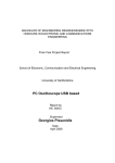
From the Department of Electronics, Computer & Mechanical Engineering
Technology, Indiana State University at Terre Haute, USA Xiaolong Li Munigala
and
S. Qing-An Zeng was able to develop the project entitled “Design and
Implementation of a Wireless Programmable Logic Controller System” in 2010.
Technological advancements has marked briskly over the past years and it has
become part of every individual’s everyday life as it has become an inevitable
need, making lives easier and more comfortable.
Through time, these
technologies have evolved into even more sophisticated models with the aim of
improving life further.
This is true with the wireless technology which had
undergone significant development that has enabled people to connect devices
with conveniences. This study had made an effort to utilize one of the wireless
technologies ZigBee to programmable logic controller (PLC) so that the remote
field devices can be controlled without the need to connect wires in between the
devices involved just like what the present study is aiming to develop.
15
Meanwhile, Yao Li of Christchurch Polytechnic Institute of Technology in
2011 authored the study Implementing ZigBee Protocol as Assignments in
Teaching Embedded Systems, a study was postulated in response to producing a
technology that would turn to benefit people in the real setting. In one of the
courses in the Bachelor of Engineering Technology programme offered at
Christchurch Polytechnic Institute of Technology, a feasible project has always
been used as assignment for teaching and assessment. Recently, included in
those assignments was to implement the ZigBee protocol in the in-house
developed micro controller training kit. It involved emerging technologies of the
wireless sensor control network in the assignment has stimulated students’
interest, not only in embedded systems but also in other areas such as wireless
communications. This proves the expanding use of wireless technology in the
techno-world.
It has been known that information transmission is apparent for the user
in the ZigBee wireless sensors network, a technology that lacks interactivity and
self-limit. A friendly interface cannot view the information in the ZigBee wireless
sensors network in a real time by a friendly interface. In this aspect, Modbus
protocol is embedded into ZigBee stack so that an interaction can be well applied
and the information can be viewed in a friendly interface. This paper, Research
on ZigBee Wireless Sensors Network Based on ModBus Protocol, delved on the
16
measures to embed the Modbus protocol into the ZigBee stack which the
Chipcon Company provided. It contains address bound mechanism, information
centralized storage, and flexible monitoring, by which the real time information
from the ZigBee wireless network can be monitored and some instructions can
be used to control the remote device in a friendly interface. Such can be used
well in the middle and small ZigBee monitoring wireless sensors network. This
has been implemented in the plant physiological ecology monitoring system.
This study was developed by Liu Yanfei, Wang Cheng, Yu Chengbo, Qiao Xiaojun
of Chengdu, China in 2009.
Indeed, wireless technology has been in demand, responding to the needs
of the continuously developing sophistication of the techno-world. According to
the needs of technology and market of new kind of smart transducer, this study,
which is based on the technology of ZigBee, the international standard
IEEE1451, and the technology of intelligent transducer, proposed a new wireless
transducer/controller Z-WPAN-ST and described its architecture and implement
technology. The hardware structure and software components of Z-WPAN-ST
which plays as a node in a WPAN are presented in detail. Several problems
relevant with the application of the new Z-WPAN-ST in supervision and control
system for gas station were also included in the discussion herein. This study,
ZigBee Based Wireless Networked Smart Transducer and Its Application in
Supervision and Control System for Natural Gas Gate Station, was postulated in
17
2009 by Meng Xiangyin,
Xiao Shide,
Xiong Ying and
Huang Huiping of
Chengdu, China.
From The Engineering Of Optical And Electronic College of ChongQing
University, Y W Zhu, X X Zhong and J F Shi in 2006 developed the project
entitled, The Design of Wireless Sensor Network System Based on ZigBee
Technology for Greenhouse. The Wireless Sensor Network, which is new in the
research field, can be used at times for signal collection, processing and
transmitting. Zigbee is one of the new Wireless sensor network technologies
that have a characteristic of less distance and low speed with a wireless network
protocol stack of IEEE 802.15.4. Traditional system to collect parameters for
Greenhouse has been widely used in agriculture recently. This traditional system
adopts wired-way wiring, which makes it complex and expensive.
Normally,
modern Greenhouse has hundreds of square meters and they may plant variety
of plants depending on different seasons. With this, there is a need to adjust the
sensors which collect parameters for Greenhouse to a better place to work
efficiently. To take up a wireless-way wiring for such system is convenient and
economical.
It is in this regard that this paper was developed to design a
wireless sensor network system based on ZigBee technology for greenhouse.
This technology offers flexibility and mobility to save cost and energy spent on
wiring. Also included in the discussion here were the framework hardware and
software structure related programming. To compare this system which uses
18
ZigBee technology with traditional wired network system for greenhouse, it has
advantage of low cost, low power and wider coverage. In addition, it complies
with IEEE802.15.4 protocol, making it convenient to communicate with other
products that comply with the protocol as well.
Bergmann, N.W., Wallace, M. and Calia, E. from the School of ITEE,
University of Queensland in St. Lucia, Queensland, Australia were able to
develop, meanwhile, the study “Low Cost Prototyping System for Sensor
Networks” in 2010.
System designs for modern wireless sensor systems are
based on low capability microprocessors and limited range radios since such
designs have small physical size and limited energy budgets. But given the fact
that these sensor nodes are based on low-cost components, development
supplies for wireless sensor network are somewhat expensive, just like the
sensor nodes. Instead of making the cost a few dollars less, these “low cost”
systems usually cost above a hundred dollars each. Such cost of the system is
affected by the wide variety of sensor nodes available, and the limited market
size for any one node. The said concern prompted the researchers to develop
this study which aims to develop a low-cost prototyping platform that is based,
as much as possible, on existing open-source PCB designs and software
environments. This project used Arduino low-cost microprocessor platform, XBEE
low-cost Zigbee networking modules, and open-source TinyOS software system.
19
From the Department of Electrical & Computer Engineering in Alabama
University, USA, Cox, D., Jovanov, E. and Milenkovic, A. developed the “Time
Synchronization for Zigbee Networks” in the year 2005.
Time synchronization,
indeed, is important for most network applications. This is true particularly in a
wireless sensor network (WSN) as a way to correlate diverse measurements from
a set of distributed sensor elements and synchronize clocks for shared channel
communication protocols.
These wireless sensors are normally designed with
very strict constraints for size, cost and, more importantly, power consumption.
The flooding time synchronization protocol (FTSP) was explicitly developed for
time synchronization of mesh-connected wireless sensor networks.
ZigBee,
however, can also accommodate master-slave networks that can be more powerefficient.
This study optimized the FTSP for master-slave WSNs and
implemented it using TinyOS 1.1.8 and ZigBee-compliant hardware.
This
approach aimed to allow not just better synchronization but as well reduced
power consumption of wireless nodes.
In 2004, Arai, F., Iwata, N. and Fukuda T. of the Department of MicroNano System Engineering of Nagoya University in Japan proposes the
“Transparent Tactile Feeling Device for Touch-Screen Interface”. The device will
give a feeling of actual pressing of the keys in the screen without interrupting
the touch screen function. This device doesn’t use force sensor or actuator
20
instead uses a specific shape of the conventional switch and haptic device to give
a feeling of clicking the touch screen display.
The “Optical Touch Screen with Virtual Force” in 2009 by Hong Zhang of
the Department of Mechanical Engineering of Rowan University uses stereovision
or pseudo-stereovision to produce a touch screen experience. Cameras are
installed at the corner of the monitor and an algorithm will compute for the
location of the pointer when it is near the screen. The paper proposes that
virtual force would be produced in the active space of the touch screen by the
positions, velocities and accelerations of the pointer. There will be an
improvement in the user interface by using the methods discussed and
presented in the paper.
Mapuans also designed their own touch screen based devices. The “Nurse
Touch Screen Device: Touch Screen Interfaced Inpatient Treatment Record
System by Marife S. Cruz, Erick Brylle T. Reyes and Michael Jeremy R. Vicedo in
the year 2010 is one of these devices. Conventional hospital inpatient records are
usually done using pen and paper, it works but as more patients come and go it
become difficult to manage, but with this device, an alternative can be found. By
digitizing the records and each device can remotely access the database; it will
21
be a lot easier. Touch screen was used because of the “touch/tap” approach in
accessing the objects and files.
Another innovation done by Mapuans dealing with touch screen is the “On
Screen Mouse Add on Frame Utilizing Array of Lasers with PS/2 Computer
Interface” by Divine Grace F. Balang and Anselie D. Magsino in 2010. Their
design is an upgrade of a regular computer mouse. It can do everything that a
regular mouse can do – like left lick, double click, right click and drag function,
but is controlled by pointing gestures like a touch screen. The device is like an
add on panel that can fit on 14.1 inches LCD screens. By using this device,
regular LCDs screen turns into touch screen with mouse button functions. It is
done by using grids of X and Y lasers. By disrupting the laser, the coordinate of
the mouse pointer is located in the screen. A microcontroller unit process all the
necessary operations - from creation of coordinates to the management of the
mouse circuit in the design.
22
CHAPTER 3
DESIGN PROCEDURES
This chapter gives the overview on how the step-by-step process used in
the assembly and development of the design prototype. This includes the
hardware and the required software. This section will briefly discuss the
components and materials used.
Start
A
Data Gathering and Research
(Related Literature/Studies/
Articles)
Assembly of Hardware
and Software
Testing Of The
Prototype
Did The Data
Prove Useful?
NO
Check For
Errors In The
System?
YES
Plan And Create
Possible System
Designs From Data
Does The System
Design Satisfies
the Condition?
Modify And
Troubleshoot The
Prototype
YES
Is The
Objective
Met?
Evaluate The Circuit
Diagram of the System
Designs
NO
NO
NO
YES
Formulate
Recommendation and
Conclusion
YES
A
END
Figure 3.1: Design Procedure Flow Chart
23
Initial Planning and Data Gathering
The group first made a flow of procedures to follow before initiating to
work on the actual prototype. The group created a flowchart in which it will be
used as our step by step guide on the different stages of the prototype design
illustrated in figure 3.1. The first and one of the most important step is the data
gathering procedure, this was done by consulting and seeking information
coming from a variety of resources such as journals, books, related studies and
articles that are helpful for making the system design. After data gathering, the
group sorted out the selection so that only the significant information will be left.
All the necessary information from the gathered data will provide solutions on
solving the problems of the design. These problems include the individual parts
and essential components for the structure of the Scoreboard Controller
prototype. Then the group builds the main concept of how the design prototype
will operate and produce the required output and what may possibly the major
parts. Figure 3.2 shows the whole idea that the group devise to use in creation
of the design prototype and Figure 3.3 represents the nature of the data flow of
the system.
Assembly of Hardware and Software
This section refers how the actual design construction of the prototype.
The group constructed the systems block diagram and flowchart as the basis
using these in consideration when creating the design. The individual
24
components are decided for construction of the schematic diagram as shown in
figures 3.4, 3.5, 3.6, 3.7 these provides as the circuit used in the prototype. After
verifying the integral parts to be utilized, the group search and canvassed for all
the materials’ prices. Table 3.1 reveals the various devices used for the prototype
and their amount when they were acquired. The datasheets of each major item
that was used are gathered in the appendix section of the document for
reference in the future. The figures mentioned illustrate the different circuit
designs in the different parts are used as the finalized circuit that composed the
designs hardware. The circuit includes how the interfaces will connect the device
or modules used to the computer. The prototype is then amassed for the final
testing. Figure 6.1 (Touch Screen Basketball Scoreboard Controller Device) of the
appendix showcase the fully assembled prototype design.
Testing of the Prototype
Testing includes various tests conducted to meet the specific objectives of
the design. To determine the efficiency and reliability of the design prototype,
several testing procedures must be done. Three major tests should be conducted
during the Testing Phase; these are the Data Accuracy Test, Range Test with
Respect to Time, and the User Interface Program Execution Test. These tests
measure the responsiveness of the prototype in accordance to the several
scenarios set. The test also determines the design efficiency in synchronization
by a given distance with various interferences, such as human bodies and
25
concretes, and the effectiveness of the design for users based on the user
interface. The purpose of Data Accuracy Test is to determine if the design
software is accurately executing the program and precisely sending the data by
verifying if the received data in the scoreboard is the same with the data in the
software and also to determine the accuracy of touch screen input device
whenever a button is pressed. The second test which is the Range Test intends
to determine the maximum distance wherein the devices can wirelessly transmit
and receive data and still be synchronized.
Formulating Conclusion and Recommendations
The conclusion and recommendations are planned after the final
examination and painstaking investigation and analysis of the system. Conclusion
responds to the designs objective were met, it also addresses if the problem was
given a solution to its problems by the developed prototype. The groups
presented recommendations that are not included in the design prototype
because of constraints such at time and money. The recommendations can be
use to further improve the system and can be utilize a reference for future study
in the field related to it. The conclusion and recommendations stated in the
document was derived from the final design prototype.
26
BILL OF MATERIALS
The table below shows all the materials used in the development of the
design with its costing without shipping cost since it depends on location.
COMPONENTS
QUANTITY
PRICE PER
PIECE
TOTAL
15” Touch Screen Kit
1
2,500.00
2,500.00
XBee-PRO® 802.15.4
2
1,700.00
3,400.00
XBee USB Adapter Board
1
2,000.00
2,000.00
Arduino Mega 2560
1
2,400.00
2,400.00
Arduino XBee Shield
1
1,000.00
1,000.00
74LS48 Decoder
17
30.00
510.00
7 Segment Display
17
20.00
340.00
1 Feet of Copper Wire
100
1.50
150.00
Total
12,300
Table 3.1: Bill of Materials
27
Hardware Development
Conceptual Diagram
Choose a
Command
USER
Execute The
Command
TOUCHSCREEN
GUI
INTERFACE
ZIGBEE RX
p
eS
Fre
LAPTOP
e
ac
XBEE
SHIELD
XBEE USB
ADAPTER
ZIGBEE TX
Use
Amplifier
(UNL2003A)
ARDUINO
MICROCONTROLLER
SCOREBOARD WITH HORN
Figure 3.2: Conceptual Diagram
28
The Design’s Conceptual Diagram, as illustrated in figure 3.2 shows the
prototype’s behavior and flow from beginning to end. The user can, choose a
command and execute the event from the software running in the computer. The
touch screen takes advantage of the GUI (Graphical User Interface) of the
software to provide the user ease of use. The Scoreboard Application will serve
as the interface between the computer and the external scoreboard. After the
user executes a command from the program, then it will send a corresponding
data to the microcontroller. The computer will first pass it to the wireless
communication device to transmit the information; this device is the Xbee
Adapter with the Zigbee mounted on it. The Zigbee Module only purpose is the
synchronization of the scoreboard software with the external scoreboard display,
it is responsible for accurate and fast wireless data transmission. The Arduino
Mega 2560 with the Arduino XBee Shield concern is that of receiving and
executing the commands that corresponds to the sent data. The next diagram
Figure 3.3 (Block Diagram) will show how each of the parts interact with one
another when integrated as one into the system and the flow of data in the
components on the system.
Block Diagram
The block diagram of the design prototype is made up of two main parts
that can be separated into five major components specifically the Touch Screen,
the Computer, the Transmitter, The Receiver and the Data Output. The touch
29
screen device provides the screen coordinates to be sent as data to the
computer when the user taps the screen. The computer side is comprised of 2
ports used to connect with the Figure 3.X (Touch Screen) and Figure 3.4 Zigbee
Transmitter Circuit. The transmitter contains a FT232RL integrated circuit and
the Zigbee. The FT232RL IC is made to convert the signals entering from a serial
port to TTL (Transistor-Transistor Logic) so that the Zigbee Transmitter can
understand the data passed to it. The Zigbee Transmitter sends the signal to its
paired Zigbee Receiver. The receiver block firstly involves the Zigbee RX that
receives the TTL signal coming from the Zigbee TX and then it transfers it to the
MCU (Microcontroller Unit) Arduino Mega 2560. The MCU then performs the
necessary data processing before it output in a 7-segment decoder. The output
component contains the 7-segment decoder that interprets the data from the
MCU to be displayed in the external scoreboard composing of 7-segment
displays.
30
Scoreboard Controller
Computer
USB Port
Touch
Screen
User Input
Transmitter
User
Input
FT232RL
Convert
Signal
Zigbee TX
TX/RX
USB Port
Scoreboard
Receiver
Signal
Arduino
2560
Process
TTL Signal
Zigbee RX
Amplified
Output
7
Segment
Display
Signals
Horn
Data Output
7
Segment
Decoder
7 Segment
Output
Amplifier
Figure 3.3: Block Diagram of Scoreboard Controller and Scoreboard
31
Schematic Diagram
Figure 3.4: Touch Screen Circuit
32
Figure 3.5: Zigbee Shield Transmitter Circuit
Figure 3.6: Arduino Zigbee Shield Receiver Circuit
33
Figure 3.7: Arduino Mega 2560 Receiver Circuit
34
The design prototype’s parts can be partitioned into four modules; the
touch screen, transmitter, receiver, and the output of the device.
The touch screen module consists of a clear touchscreen panel you will
install in front of your LCD monitor screen, a Zilog z8F042A microcontroller, 110220VAC and/or 7VDC power supply adapter, and a serial cable. This would be
connected to the PC COM port using a serial cable. If the Laptop does not have a
COM port, a USB to RS-232 cable may be used to connect it to an available USB
port. The PL2303 driver must be installed along with the touch screen calibration
program.
The transmitter generally make up of FT232RL, and the XBee-PRO®
802.15.4 module. The FT232RL converts signals coming from a serial port and
change it to a TTL. The XBee-PRO® 802.15.4 module is used to communicate
and deliver the signal from the computer to the receiver.
The receiver consists of the XBee-PRO® 802.15.4 module, the Arduino
Zigbee Shield, and the Arduno Mega 2560. The XBee-PRO® 802.15.4 module
receives the signal from the transmitter and passes it to the microcontroller. The
Arduino Zigbee Shield is the passage way for the signal to travel from the Zigbee
Module to the Arduino Mega 2560. The Arduino Mega 2560 is the microcontroller
that performs decoding of data transmitted to a functional form by the 7
segment driver. The output of the device comprises of the 7-Segment Drivers
and 7 Segment displays.
35
Software Development
Our group’s main focus in software development is to create a software
program which will act as the backbone of the entire system. There are 2 main
task of the program, the first is that it should enable the user to operate the
program easily and it must behave similarly to a standard basketball scoreboard;
secondly it is going to be used to synchronized the data from the software to be
displayed in the portable scoreboard using the interface of the Zigbee module for
data transmission. Visual C# 2010 is an object oriented program combined with
.NET FRAMEWORK 4.0 will create a rich user interface that will provide ease of
use. Also with using these tools to construct software it can interact with a USB
port of a computer since it can reference a variety of objects for the design
implementation. For the flow of the system figure 3.6 will illustrate the nature of
the design prototype. With incorporating different software engineering
documentation methodologies as shown in figure 3.7 for the Scoreboard
Controller Software, as well as providing an interface to the application software
as demonstrated in figure 3.8 to 3.10.
SYSTEM FLOWCHART
The software event executions of the design prototype are shown in figure
3.6 System Flowchart. It displays the concise flow of the program and its
relations. Starting the program will then initiate the Scoreboard software loading
it to memory, where all the operations can be carried out.
36
BEGIN
A
C
LOAD
PROGRAM
SHOW
SCOREBOARD
LOAD
DEFAULT
SETTINGS
LOAD
GAME
TIME
SHOW
GAME
OPTIONS
WINDOW
SHOW
CHANGE
TIME
WINDOW
B
B
PLAY
BUTTON
CLICK?
SHOT CLOCK
AND GAME
TIMER START
YES
TRANSMIT
DATA VIA
ZIGBEE
UPDATE
EXTERNAL
SCOREBOARD
NO
CHANGE
GAME TIME
CHOOSE
OPTIONS
STOP
BUTTON
CLICK?
SHOT CLOCK
AND GAME
TIMER STOP
YES
ARE
SETTINGS
VALID
NO
HOME
CONTROL
BUTTONS
CLICK?
SAVE
OPTIONS
NO
AWAY
CONTROL
BUTTONS
CLICK?
EXECUTE
BUTTON
CONTROL
EVENT
YES
TRANSMIT
DATA VIA
ZIGBEE
NO
TIMER
BUTTONS
CLICK?
SHOT CLOCK
AND GAME
TIMER STOP
YES
UPDATE
EXTERNAL
SCOREBOARD
C
NO
OPTIONS
BUTTONS
CLICK?
SHOT CLOCK
AND GAME
TIMER STOP
YES
IS THE
CHANGE
VALID?
YES
YES
EXECUTE
BUTTON
CONTROL
EVENT
YES
NO
LOAD SAVED
OPTION IN
SCOREBOARD
SAVE
CHANGES TO
GAME TIME
TRANSMIT
DATA VIA
ZIGBEE
UPDATE
EXTERNAL
SCOREBOARD
LOAD CHANGE
GAME TIME IN
SCOREBOARD
WINDOW
A
B
NO
B
RESET
SHOT
CLOCK
BUTTON
CLICK?
TRANSMIT
DATA VIA
ZIGBEE
UPDATE
EXTERNAL
SCOREBOARD
B
B
NO
NO
CLOSE
PROGRAM?
YES
END
Figure 3.8: System Flowchart
37
NO
USE CASE DIAGRAM
SCOREBOARD
Add/Remove Score Events
Add/Remove Foul Events
Add/Remove Timeout Events
Change Game Setting Event
Change Time Event
Play/Stop Time Event
Reset Shot Clock Event
User
Figure 3.9: Use-Case Diagram
In figure 3.7 presents the direct relationship of what the user can execute
during the usage of the software program, the use case diagram for the
prototype – the user is given access to all of the features available within the
Scoreboard application that was created using Microsoft Visual C# and .NET
FRAMEWORK 4.0. The Use-Case illustrates the different actions (add/remove
score, fouls and timeouts, change scoreboard settings and game time, play/stop
game time, and reset shot clock) the User will be able to do. All actions will lead
to synchronizing with the external scoreboard via Zigbee’s data transmission. The
Add/Remove Score Events allows the user to add or remove from the score of
any team corresponding to the text seen on the button that handles the event.
The Add/Remove Foul Events allows the user to add or remove from the foul of
any team. The Add/Remove Timeout Events allows the user to add or remove
38
from the timeout of any team. The Change Game Setting Event gives the user
freedom to choose the combination of options on how the game will behave. The
Change Time Event permits manipulation of time when the user needs to adjust
the time of the game. The Play/Stop Time Event enables or disables the timer of
the game. And lastly the reset shot clock event provides an option to the user to
reset the shot clock while the timer is running. All this was in consideration in
making an program resembling a standard scoreboard.
ACTIVITY DIAGRAM
User
Open
Scoreboard
Add/Remove
Any Team Score
Add/Remove
Any Team Fouls
Add/Remove
Any Team
Timeouts
Change
Scoreboard
Settings
Change Game
Time
Play/Stop Game
Time
Reset Shot Clock
Figure 3.10: Activity Diagram
For figure 3.8 it shows the different task that the user can perform in the
Scoreboard Application Software. The user can add scores (+1, +2, +3, or -1)
39
using an event to the teams, It also includes the ability to increase or decrease
the value by 1 of foul and/or timeout events even if the game time is ticking.
Every time the data changes on the scoreboard program, it will be reflected on
to the external scoreboard because they are synchronized. And also change the
status of the timer to play or to stop events and it is able to reset the shot clock
in anytime of the game. The game time is accurate to a hundredth of a
millisecond making it accurate enough for being a basketball scoreboard.
The software can also change the setting of the game, this feature
enables the user to set the total number of minutes in a quarter, how many
periods in a game, maximum number of team fouls and timeouts in a quarter,
and the shot clock timer. Another aspect of the program is that it can change the
game time (minutes, seconds, and milliseconds), the period and shot clock.
INTERFACING THE DESIGN TO THE PC
The design prototype’s hardware and software parts are joined together
with the use of the computers USB (Universal Serial Bus) port. When connection
is established between the two, then the system is ready for testing.
40
Figure 3.11: Scoreboard Application Main Page
Figure 3.9 showcase the Main page of the Scoreboard Application for the
design. This window displays is where the user will focus almost all the time. The
page contains the different status of the game in the view of a scoreboard, such
event are playing or stopping the game, reset the shot clock accordingly. The
user is able to increase or decrease the scores, fouls and timeouts of the teams.
It is also the way to start or stop the game. The user can also access the Change
Time Page and Options Page.
41
Figure 3.12: Scoreboard Application Options Page
Figure 3.10 shows the Option Page of the design. This is the part of the
Scoreboard Application that allows the user to choose different combinations of
setting for the in game regulations like the minutes in a quarter, the number
period, limits of number of fouls and timeouts, and shot clock. The most
important part to be selected is the COM port selection wherein the user needs
to correctly choose the right port to allow data transmission.
42
Figure 3.13: Scoreboard Application Change Time Page
Figure 3.11 shows the Change Time Page of the design. This part of the
software permits the adjustment of the game timer (minutes, seconds and
milliseconds), period of the game, and shot clock. When the page loads, it gets
the information on the current time, period and shot clock.
PROTOTYPE DEVELOPMENT
In the design, doing the hardware part was undemanding of time than
that of its software counterpart. The main reason for this is that the hardware
43
part only focused on receiving the data transmitted for synchronization of the
display of the external hardware from the program. The hardware was interfaced
to the computer by the use of a USB port for both the Touch Screen interface
and the Zigbee component.
With the schematic diagrams from the previous sections of this chapter,
since two modules were bought for the scoreboard controller, one of which is the
Parallax Xbee USB Adapter Board module and the e-Gizmo 15” Touch Screen
Set. As for the external scoreboard prepared for demonstration, it was made up
of the Arduino Mega 2560 Board containing the ATmega2560 microcontroller,
Arduino Xbee Shield for holding the Zigbee. For the software part, the Arduino
Mega 2560 was programmed using the Arduino IDE. It is a high level
programming language akin to C++ programming language and is specifically for
Arduino Boards. After the program had been constructed, it was uploaded into
the Arduino Mega 2560 Board using the same program.
The touch screen module uses PL2303 driver that must be installed along
with the touch screen calibration program. This would be connected to the PC
COM port using a serial cable. A USB to RS-232 cable is used to connect it to an
available USB port. Calibration is done after this setup.
The transmitter generally make up of FT232RL which converts signals
coming from a serial port and change it to a TTL, and the XBee-PRO® 802.15.4
module which communicates and delivers the signal from the computer to the
44
receiver. This is installed and connected to the PC via USB port and is controlled
by the program.
The receiver on the other hand which is the XBee-PRO® 802.15.4
module, the Arduino Zigbee Shield, and the Arduno Mega 2560 receives the
signal from the transmitter and passes it to the microcontroller. The Arduino
Zigbee Shield is the passage way for the signal to travel from the Zigbee Module
to the Arduino Mega 2560. The Arduino Mega 2560 performs decoding of data
transmitted to a functional form by the 7 segment driver. The output of the
device comprises of the 7-Segment Drivers and 7 Segment displays which is
powered by an at least 6V power source.
45
CHAPTER 4
TESTING, PRESENTATION, AND INTERPRETATION OF DATA
This chapter shows the various tests conducted to meet the specific
objectives of the design. To determine the efficiency and reliability of the design
prototype, several testing procedures must be done. Three major tests were
conducted during the Testing Phase; these are the Data Accuracy Test, Range
Test, and the User Interface Program Execution Test. These tests measure the
responsiveness of the prototype in accordance to the several scenarios set. The
test also determines the design efficiency in synchronization by a given distance
with various interferences, such as people and concretes, and the effectiveness
of the design for users based on the user interface.
A. Data Precision Test
Purpose
To determine if the design software is accurately executing the program
and precisely sending the data by verifying if the received data in the scoreboard
is the same with the data in the software and also to determine the accuracy of
touch screen input device whenever a button is pressed.
46
Assumptions
The scoreboard should show the score and other information as controlled
by the computer software. Whenever the user changes or edits any part in the
software application using the touch screen device the corresponding change
should occur on the scoreboard regardless of time synchronization and distance.
There would be two trials to test each button, the first trial will come after
opening the software application and the second is after the first trial wherein
the previous data are still stored.
Procedure:
1. Connect the Touch screen device and adjust its settings;
2. Connect the Zigbee receiver and transceiver to the scoreboard and to the
computer respectively;
3. Open the Scoreboard application software;
4. Choose the COM setting of the Zigbee for the computer;
5. Click one button for trial testing;
6. Record the result;
7. Repeat procedure 5 and 6 for another button; and
8. Repeat procedure 5 to 7 for the another trial.
47
Button Name
HomeScorePlus1_btn
HomeScorePlus2_btn
HomeScorePlus3_btn
HomeScoreMinus1_btn
HomeFoulsPlus1_btn
HomeFoulsMinus1_btn
HomeTimeoutPlus1_btn
HomeTimeoutMinus1_btn
AwayScorePlus1_btn
AwayScorePlus2_btn
AwayScorePlus3_btn
AwayScoreMinus1_btn
AwayFoulsPlus1_btn
AwayFoulsMinus1_btn
AwayTimeoutPlus1_btn
AwayTimeoutMinus1_btn
Play_btn
Stop_btn
ResetClock_btn
GUI
Correct
Correct
Correct
Correct
Correct
Correct
Correct
Correct
Correct
Correct
Correct
Correct
Correct
Correct
Correct
Correct
Correct
Correct
Correct
Remarks
Scoreboard
Correct
Correct
Correct
Correct
Correct
Correct
Correct
Correct
Correct
Correct
Correct
Correct
Correct
Correct
Correct
Correct
Correct
Correct
Correct
Table 4.1: Data Accuracy Test Trial 1 Results
The first trial tests if the data from initial state of the software application
will change when a button is pressed and will have the same output on the
scoreboard.
48
Button Name
HomeScorePlus1_btn
HomeScorePlus2_btn
HomeScorePlus3_btn
HomeScoreMinus1_btn
HomeFoulsPlus1_btn
HomeFoulsMinus1_btn
HomeTimeoutPlus1_btn
HomeTimeoutMinus1_btn
AwayScorePlus1_btn
AwayScorePlus2_btn
AwayScorePlus3_btn
AwayScoreMinus1_btn
AwayFoulsPlus1_btn
AwayFoulsMinus1_btn
AwayTimeoutPlus1_btn
AwayTimeoutMinus1_btn
Play_btn
Stop_btn
ResetClock_btn
GUI
Correct
Correct
Correct
Correct
Correct
Correct
Correct
Correct
Correct
Correct
Correct
Correct
Correct
Correct
Correct
Correct
Correct
Correct
Correct
Remarks
Scoreboard
Correct
Correct
Correct
Correct
Correct
Correct
Correct
Correct
Correct
Correct
Correct
Correct
Correct
Correct
Correct
Correct
Correct
Correct
Correct
Table 4.2: Data Accuracy Test Trial 2 Results
The second trial tests if the data from the previous state of the software
application will change correspondingly when a button is pressed.
Data Interpretation and Analysis
Table 4.1 shows that all the software application buttons are executing as
programmed and are sending the data accurately as shown on the remarks as
49
“Correct.” This is the first trial which started from zero scores, zero fouls and 6
timeouts each team. Table 4.2 now shows the second trial which shows that the
scores, fouls and timeouts can be controlled by either adding or subtracting. The
results in tables 4.1 and 4.2 illustrate that the data are accurately sent and
received. This also gives a significant outcome to the testing of the touch screen
as input device, which means that all the buttons are working through touch
screen.
B. Range Test
Purpose
To determine the maximum distance wherein the devices can wirelessly
transmit and receive data and still be synchronized.
Assumptions
The Zigbee module is a technology meant for wireless communication of
two different components. As with the design, the prototype can be divided into
two major components, a transmitter and receiver.
The tests will undergo three trials, first trial is for a straight and
unobstructed hallway, second trial is for a randomly obstructed hallway (with
people, walls and other things), and third trial is for elevated transmission (with
walls and ceilings). The results shall be coming from the Range Tester
50
application from the Zigbee manufacturer and shall give a result in percent of
efficiency of transmission which also denotes efficiency of synchronization.
Procedure:
1. Define the distances where the ZigBee will be tested;
2. Connect the Touch screen device and adjust its settings;
3. Connect the Zigbee receiver and transceiver to the scoreboard and to the
computer respectively;
4. Open the Scoreboard application software;
5. Choose the COM setting of the Zigbee for the computer;
6. Position the scoreboard to the distance defined on the first procedure;
7. Press the buttons for trial testing;
8. Check to see if the clocks have been synchronized;
9. Record the result; and
10. Repeat the procedures 7-9 for another distance.
Range Test 4th Floor
Range
Trial 1
Trial 2
Trial 3
Interference
30.87 m
100%
100%
100%
None
45.37 m
100%
100%
100%
None
72.77 m
100%
100%
100%
None
83.04 m
100%
100%
100%
None
Table 4.3: ZigBee Range 4th Floor Test results
51
Range Test 3rd Floor
Range
Trial 1
Trial 2
Trial 3
Interference
31.09 m
100%
100%
100%
People
45.52 m
99%
98%
99%
People
72.86 m
97%
98%
98%
People
83.12 m
98%
96%
97%
People
Table 4.4: ZigBee Range 3rd Floor Test results
Data Interpretation and Analysis
The test results tabulated in Table 4.3 shows that the Zigbee
specifications from the datasheet are consistent wherein it can transmit
information without significant delay within line of sight without obstruction. As
shown in Table 4.4, the data were all transmitted during the testing but a
significant decrease on percent of reliability occurred as compared from those in
Table 4.3.
This means that the interference due to random number of people even at
83 meters would not affect the synchronization of transmission between the
controller and the scoreboard.
52
C. USER INTERFACE PROGRAM EXECUTION TEST
The program execution test is the test case analysis for the programs of
the Visual C# application of the software application. The test aims to check the
correctness of the execution of the program and discover if there are any
unwanted errors or bugs between the expected output and the actual output of
the programs.
The Program Execution test was done by following the possible test case
conditions. The steps are as follows:
1. Do the specified condition presented in the test case table;
2. If the test results to an expected output, mark the record as passed;
else mark it as failed with the date on which it had failed;
3. The results were then listed side by side with the expected output and
judge if it is acceptable for the proposed application or not;
4. After testing all of the program’s test case conditions, do the necessary
debugging;
5. Re-do the routine to check if the other part of the program had an
effect to the modification; and
6. End the tests if all of the conditions have been finally met.
The test case, like any programming tests, is a trial and error procedure.
This is for the sake of ensuring that no bugs will be left behind and that the
53
debugging done on one part of the screen doesn’t have any negative effect to
the other – and if it does then re-do another debugging.
TEST CASE ANALYSIS
Screen
Test
Case
Game
Options
Event
Screen
Game
Time
Test
Game
Options
Event
Screen
Game
Period
Test
Game
Options
Event
Screen
Game
Fouls
Test
Game
Options
Event
Screen
Game
Timeouts
Test
Game
Options
Event
Screen
Game
Shot
Clock
Test
Condition
Modify the
Selected
Event Time
From the
Numerical
Drop Down
List
Modify the
Selected
Game Period
From the
Numerical
Drop Down
List
Modify the
Selected
Game Fouls
From the
Numerical
Drop Down
List
Modify the
Selected
Game
Timeouts From
the Numerical
Drop Down
List
Modify the
Selected
Game Shot
Clock From the
Numerical
Drop Down
List
Expected
output
Actual
Output
Result
Modified
Game
Time
Game
Time
Modify
Correct
Modified
Game
Period
Game
Period
Modify
Correct
Modified
Game
Fouls
Game
Fouls
Modify
Correct
Modified
Game
Timeouts
Game
Timeouts
Modify
Correct
Modified
Game
Shot
Clock
Game
Shot
Clock
Modify
Correct
54
Game
Options
Event
Screen
Game
Options
Event
Screen
COM
Port Test
Modify the
Selected COM
Port From the
Numerical
Drop Down
List
Selected
COM Port
COM
Port
Select
Correct
SAVE
Test
Click SAVE
button
Selected
Save
Options
Save
Correct
Table 4.5a Game Options Event Screen Test Case
Screen
PC
Scoreboard
Screen
PC
Scoreboard
Screen
PC
Scoreboard
Screen
PC
Scoreboard
Screen
Test
Case
Home
Score
Plus 1
Test
Home
Score
Plus 2
Test
Home
Score
Plus 3
Test
Home
Score
Minus 1
Test
Condition
Expected
output
Actual
Output
Click Home
Score Plus 1
Add Home
Score to
Output
Screen
Home
Score
Plus 1
Correct
Click Home
Score Plus 2
Add Home
Score to
Output
Screen
Home
Score
Plus 2
Correct
Click Home
Score Plus 3
Add Home
Score to
Output
Screen
Home
Score
Plus 3
Correct
Click Home
Score Minus 1
Subtract
Home
Score
from
Output
Screen
Home
Score
Minus 1
Correct
Result
55
PC
Scoreboard
Screen
Home
Fouls
Plus 1
Test
Click Home
Fouls Plus 1
Add Home
Fouls to
Output
Screen
Home
Fouls
Plus 1
Correct
PC
Scoreboard
Screen
Home
Fouls
Minus 1
Test
Click Home
Fouls Minus 1
Subtract
Home
Fouls from
Output
Screen
Home
Fouls
Minus 1
Correct
PC
Scoreboard
Screen
Home
Timeout
Plus 1
Test
Click Home
Timeout
Plus 1
Add Home
Fouls to
Output
Screen
Home
Timeout
Plus 1
Correct
PC
Scoreboard
Screen
Home
Timeout
Minus 1
Test
Click Home
Timeout
Minus 1
Subtract
Home
Fouls from
Output
Screen
Home
Timeout
Minus 1
Correct
Click Away
Score Plus 1
Add Away
Score to
Output
Screen
Away
Score
Plus 1
Correct
Click Away
Score Plus 2
Add Away
Score to
Output
Screen
Away
Score
Plus 2
Correct
Click Away
Score Plus 3
Add Away
Score to
Output
Screen
Away
Score
Plus 3
Correct
PC
Scoreboard
Screen
Away
Score
Minus 1
Test
Click Away
Score Minus 1
Subtract
Away
Score
from
Output
Screen
Away
Score
Minus 1
Correct
PC
Scoreboard
Screen
Away
Fouls
Plus 1
Test
Click Away
Fouls Plus 1
Add Home
Fouls to
Output
Screen
Home
Fouls
Plus 1
Correct
PC
Scoreboard
Screen
PC
Scoreboard
Screen
PC
Scoreboard
Screen
Away
Score
Plus 1
Test
Away
Score
Plus 2
Test
Away
Score
Plus 3
Test
56
Click Away
Fouls Minus 1
Subtract
Away
Fouls from
Output
Screen
Away
Fouls
Minus 1
Correct
Away
Timeout
Plus 1
Test
Click Away
Timeout
Plus 1
Add Away
Fouls to
Output
Screen
Away
Timeout
Plus 1
Correct
PC
Scoreboard
Screen
Away
Timeout
Minus 1
Test
Click Away
Timeout
Minus 1
Away
Timeout
Minus 1
Correct
PC
Scoreboard
Screen
Play Test
Click Play
Time
Plays
Correct
PC
Scoreboard
Screen
Stop Test
Click Stop
Time
Stops
Correct
PC
Scoreboard
Screen
Reset
Clock
Test
Click Reset
Clock
Time
Reset
Correct
PC
Scoreboard
Screen
Away
Fouls
Minus 1
Test
PC
Scoreboard
Screen
Subtract
Away
Fouls from
Output
Screen
Time
Plays in
Output
Screen
Time
Stops in
Output
Screen
Time
Resets in
Output
Sceen
Table 4.5b PC Scoreboard Screen Test Case
57
DISCUSSION OF RESULTS
Although the program was debugged during the programming phase, a
test case was made to provide documentation and an additional test as well. The
application was tested in all possible output in every possible input to prevent
unexpected error and loss of data. Base on the judgment we can say that the
program does satisfy the criteria to be able to provide signal for synchronization
and a database for event manager Bookmark error free and bug free.
58
Chapter 5
CONCLUSION AND RECOMMENDATION
This chapter presents the overall conclusion of the design by
answering the objectives of the design problem. The results of the various
testing procedures are summarized and theoretical analyses are clearly
defined. This chapter also includes the statements that suggest the need for
further studies with reference to the delimitations of the design. The
recommendation cites what else can be done for the improvement of the
design.
CONCLUSION
The designers were able to create a wireless basketball scoreboard
synchronizer that can be easily controlled using a user-friendly graphical userinterface program and a touch screen input in which the information from the
software are sent to the scoreboard without significant delay, thus adds
portability and mobility for the users and eliminates setting up messy wires.
Accurate data transmission from the software to the actual scoreboard
was achieved according to the results of the testing. The laptop computer was
able to communicate using the Zigbee to the program written in the Arduino
which controls the scoreboard. The device can transmit data without delay within
80m to 100m if there is no physical obstruction or interference. However, if there
59
are minor interference and obstruction such as human bodies and walls, the
range of transmission is lessen with a 1.67% difference compare to the latter.
The design also develops software that will allow easy control using the
computer to communicate with the ZigBee module. The Visual C#.NET is the
programming tool that was used.
Visual C#.NET provides a well-organized
approach to writing programs that are clearer, easier to test, debug and can be
easily modified. The software testing results shows that the program created in
Visual C#.NET was able to successfully control and make a link for the device
and the PC. The program application is a vital part of the design wherein the
user is able to visually see how to update the scoreboard with an assurance that
the information is also shown to the actual scoreboard.
RECOMMENDATION
The software could be improved if it would be interoperable to other
operating systems other that Windows. The system requirements for the
software are also strict which could be more flexible if the program could be
modified to work on lower versions of Windows. The GUI could also be improved
by lessening the buttons and adding more automation to the program
60
The touch screen can also be improved to a more sensitive touch screen
module. Since the touch screen is only fixed to 15-inch monitors, it must be
replaced if the laptop monitor is smaller or bigger than the touch screen. Touch
screen technology is also subject to further studies since tablets and I-pod are
emerging nowadays.
The Zigbee module operates up to 100 meters urban areas or indoors and
1500 meters in line of sight or outdoors. It can only be in synchronizing with one
scoreboard. Another design could be one-to-many Zigbee transmission. This
would require more Zigbee and a different type of data transmission such as
broadcast transmission.
The design could have a security features and database to improve the
automation and control of the basketball games. This would need a back-end
database and a security code. This improvement will help basketball committees
to easily record the scores and other information of the game.
61
REFERENCES
Arai, F.; Iwata, N.; Fukuda, T. (2004) Transparent Tactile Feeling Device for
Touch-Screen Interface. IEEE Research Paper.
Balang, D. G. T., Magsino, A. D. (2010) On Screen Mouse Add On Frame Utilizing
Array of Lasers with PS/2 Computer Interface. Mapua Design Paper
Bergmann, N.W. Wallace, M. Calia, E. (2010). Low cost prototyping system for
sensor networks. IEEE Research Paper.
Cox, D., Jovanov, E., Milenkovic, A. (2005) Time synchronization for ZigBee
networks. IEEE Research Paper.
Cruz, M. S., Reyes, E. B. T., Vicedo, M. J. R. (2010) Nurse Touch Screen Device:
Touch Screen Interfaced Inpatient Treatment Record System. Mapua Design
Paper
Li, X., Munigala, S., Zeng Q. (2010) Design and Implementation of a Wireless
Programmable
Logic
Controller
System.
IEEE
Research
Paper
Li, Y. (2011) ZigBee Protocol as Assignments in Teaching Embedded Systems.
IEEE Research Paper
Xiangyin, M., Shide, X., Ying, X., Huiping, H. (2009) ZigBee-Based Wireless
Networked Smart Transducer and its Application in Supervision and Control
System for Natural Gas Gate Station. IEEE Research Paper
62
Yanfei, L., Cheng, W., Chengbo, Y., Xiaojun, Q. (2009) Research on ZigBee
Wireless Sensors Network Based on ModBus Protocol. International Forum on
Information Technology and Applications , Volume 1, pages 487-490.
Zhang, H. (2009) Optical Touch Screen with Virtual Force. IEEE Research Paper
Zhu, Y.W., Zhong, X. X. and Shi, J. F. (2006) The Design of Wireless Sensor
Network System Based on ZigBee Technology for Greenhouse. Journal of
Physics: Conference Series, Volume 48, pages 1195-1199.
63
APPENDICES
64
Appendix A
OPERATIONS MANUAL
1. System Requirement
o Pentium 4 processor 1.6GHz or equivalent
o 512MB RAM or higher
o Microsoft Windows XP or higher
2. Installation Procedure
o Attach the Zigbee Transceiver to the laptop.
o Attach the Zigbee Receiver to the scoreboard.
o Attach the Touch Screen module to the laptop.
o Turn on the Scoreboard.
o Run the scoreboard application on the laptop.
3. User’s Manual
o Run Scoreboard.exe
65
o Touch Option
o Enter desired Game Options
o Choose the right COM PORT
o Touch Save
o Start the scoreboard by touching Play
o Touch Stop to stop the game
o Touch Time to adjust Time settings
o Touch Home +1,+2,+3 to add to Home score
o Touch Away +1,+2,+3 to add to Away score
o Touch Home Foul +1,-1 to change Foul
o Touch Away Foul +1,-1 to change Foul
o Touch Home Timeout +1,-1 to change Timeout
o Touch Home Timeout +1,-1 to change Timeout
o Touch Reset Clock to reset shotclock
4. Troubleshooting
a. Scoreboard digits are all zeros
o Choose the right COM Port when starting the application
5. Error Definition
a. Check COM Port Settings – Error in com port setting.
66
Appendix B
Pictures of Prototype
Figure 6.1: Full Prototype
The figure above shows the full prototype connected to a laptop
computer.
67
Figure 6.2: Touchscreen Controller
The figure above shows the control board of the touchscreen. It’s from eGizmo.
68
Figure 6.3: Touchscreen Set
The entire Touchscreen set kit from e-Gizmo.
69
Appendix C
PROGRAM LISTING
C# Program
From Scoreboard.cs
using System;
using System.Collections.Generic;
using System.ComponentModel;
using System.Data;
using System.Drawing;
using System.Linq;
using System.Text;
using System.Windows.Forms;
using System.Threading;
namespace ScoreBoard
{
public partial class frmScoreboard : Form
{
#region Global_Data_Declaration
bool booltmrPause = false;
Int32 intQuarterTimerMin,
intQuarterTimerSec,
intQuarterMiliSecond,
intShotClockTime,
intShotClockMili = 9,
intCurrentPeriod,
intMaxPeriod;
string strMaxPeriod,
strMaxFouls,
strShotClock,
strQuarterTime,
strMaxTimeout;
#endregion
#region Initailize_Components
public frmScoreboard()
{
InitializeComponent();
70
}
#endregion
#region Load Form
private void frmScoreboard_Load(object sender, EventArgs e)
{
MessageBox.Show("Make sure to change the settings first before " +
"starting the game.\nPress Alt + O to open Options Menu" +
"\nAlways Select The Right COM port in Options Menu",
"Attention!", MessageBoxButtons.OK, MessageBoxIcon.Exclamation);
}
#endregion
#region QuarterTimer & ShotClock
private void timer1_Tick(object sender, EventArgs e)
{
//Code For The Shot Clock
if (intQuarterTimerMin == 0 && intQuarterTimerSec == 0 &&
intQuarterMiliSecond == 0)
{
goto QUARTERTIMER;
}
else if (intShotClockTime > 0)
{
if (intShotClockMili > 0)
{
intShotClockMili--;
}
else
{
intShotClockMili = 9;
lblTimerSC.Text = Convert.ToString(intShotClockTime 1).PadLeft(2, '0');
intShotClockTime = Convert.ToInt32(lblTimerSC.Text);
serialPort1.WriteLine("C " + lblTimerSC.Text);
}
}
else //End Shot Clock
{
71
{
}
tmrTime.Enabled = false;
booltmrPause = false;
ResetSC();
}
QUARTERTIMER:
//Code For The Game Time
if (intQuarterTimerMin > 0)
{
if (intQuarterMiliSecond > 0)
{
intQuarterMiliSecond--;
lblMiliSeconds.Text = Convert.ToString(intQuarterMiliSecond);
}
else if (intQuarterTimerSec > 0)
{
intQuarterMiliSecond = 9;
lblMiliSeconds.Text = Convert.ToString(intQuarterMiliSecond);
lblTimerSeconds.Text = Convert.ToString(intQuarterTimerSec 1).PadLeft(2, '0');
intQuarterTimerSec = Convert.ToInt32(lblTimerSeconds.Text);
serialPort1.WriteLine("S " + lblTimerSeconds.Text);
}
else if (intQuarterTimerSec == 0 && intQuarterTimerMin != 0)
{
intQuarterMiliSecond = 9;
lblMiliSeconds.Text = Convert.ToString(intQuarterMiliSecond);
lblTimerMinutes.Text = Convert.ToString(intQuarterTimerMin 1).PadLeft(2, '0');
intQuarterTimerMin--;
lblTimerSeconds.Text = "59";
intQuarterTimerSec = 59;
serialPort1.WriteLine("M " + lblTimerMinutes.Text);
Thread.Sleep(10);
serialPort1.WriteLine("S " + lblTimerSeconds.Text);
}
}
else if (intQuarterTimerMin == 0)
{
if (intQuarterMiliSecond > 0)
{
intQuarterMiliSecond--;
72
lblMiliSeconds.Text =
Convert.ToString(intQuarterMiliSecond);//.PadRight(2, '0');
serialPort1.WriteLine("S " + lblMiliSeconds.Text.PadLeft(2,'0'));
}
else if (intQuarterTimerSec > 0)
{
intQuarterMiliSecond = 9;
lblMiliSeconds.Text = Convert.ToString(intQuarterMiliSecond);
serialPort1.WriteLine("M " + lblTimerSeconds.Text);
lblTimerSeconds.Text = Convert.ToString(intQuarterTimerSec 1).PadLeft(2, '0');
intQuarterTimerSec = Convert.ToInt32(lblTimerSeconds.Text);
serialPort1.WriteLine("S " + lblMiliSeconds.Text.PadLeft(2,'0'));
}
else if (intQuarterTimerSec == 0 && intQuarterMiliSecond != 0)
{
intQuarterMiliSecond = 9;
lblMiliSeconds.Text = Convert.ToString(intQuarterMiliSecond);
serialPort1.WriteLine("S " + lblMiliSeconds.Text);
lblTimerSeconds.Text = Convert.ToString(intQuarterTimerSec 1).PadLeft(2, '0');
serialPort1.WriteLine("M " + lblTimerSeconds.Text);
}
else if (intQuarterTimerSec == 0 && intQuarterTimerMin == 0 &&
intQuarterMiliSecond == 0)
{
intCurrentPeriod = Convert.ToInt32(lblPeriodNumber.Text) + 1;
int HomeScore = Convert.ToInt32(lblHomeScore.Text),
AwayScore = Convert.ToInt32(lblAwayScore.Text);
if (intCurrentPeriod < intMaxPeriod && intCurrentPeriod > 0)
{
lblPeriodNumber.Text =
Convert.ToString(intCurrentPeriod).PadLeft(2, '0');
serialPort1.WriteLine("P " + lblPeriodNumber.Text);
lblTimerMinutes.Text = strQuarterTime;
serialPort1.WriteLine("M " + lblTimerMinutes.Text);
intQuarterTimerMin = Convert.ToInt32(strQuarterTime);
booltmrPause = false;
tmrTime.Enabled = false;
ResetSC();
}
73
AwayScore))
else if ((intCurrentPeriod > intMaxPeriod) && (HomeScore ==
{
selected
string strOverTime = "05";
// add serialport for labels periodnumber,minutes,seconds
// add into options overtime length and comport should be
lblPeriodNumber.Text = "00";
serialPort1.WriteLine("P " + lblPeriodNumber.Text);
lblTimerMinutes.Text = strOverTime;
serialPort1.WriteLine("M " + lblTimerMinutes.Text);
intQuarterTimerMin = Convert.ToInt32(strQuarterTime);
booltmrPause = false;
tmrTime.Enabled = false;
ResetSC();
MessageBox.Show("Over Time!");
}
else if ((intCurrentPeriod > intMaxPeriod) && (HomeScore !=
AwayScore))
{
}
booltmrPause = false;
tmrTime.Enabled = false;
MessageBox.Show("The Game is Finished");
}
}
END: { }
}
#endregion
#region Home Controls
private void btnHomeAdd1_Click(object sender, EventArgs e)
{
lblHomeScore.Text =
Convert.ToString(Convert.ToInt32(lblHomeScore.Text) + 1);
//this line add 1 point to the score of the Home Team
serialPort1.WriteLine("H" + lblHomeScore.Text.PadLeft(3, '0'));
//This statements for serial port transmission
}
private void btnHomeAdd2_Click(object sender, EventArgs e)
74
{
lblHomeScore.Text =
Convert.ToString(Convert.ToInt32(lblHomeScore.Text) + 2);
//this line add 2 point to the score of the Home Team
serialPort1.WriteLine("H" + lblHomeScore.Text.PadLeft(3, '0'));
//This statements for serial port transmission
ResetSC();
}
private void btnHomeAdd3_Click(object sender, EventArgs e)
{
lblHomeScore.Text =
Convert.ToString(Convert.ToInt32(lblHomeScore.Text) + 3);
//this line add 3 point to the score of the Home Team
serialPort1.WriteLine("H" + lblHomeScore.Text.PadLeft(3, '0'));
//This statements for serial port transmission
ResetSC();
}
private void btnHomeSub1_Click(object sender, EventArgs e)
{
if (lblAwayScore.Text != "0")
{
lblAwayScore.Text =
Convert.ToString(Convert.ToInt32(lblAwayScore.Text) - 1);
//this line minus 1 point to the score of the Home Team
serialPort1.WriteLine("H" + lblAwayScore.Text.PadLeft(3, '0'));
//This statements for serial port transmission
}
}
+ 1);
private void btnHomeFoulAdd_Click(object sender, EventArgs e)
{
if (lblHTFouls.Text != strMaxFouls)
{
lblHTFouls.Text = Convert.ToString(Convert.ToInt32(lblHTFouls.Text)
//this line add 1 foul of the Home Team
serialPort1.WriteLine("O " + lblHTFouls.Text);
//This statements for serial port transmission
tmrTime.Enabled = false;
}
}
75
- 1);
private void btnHomeFoulSub_Click(object sender, EventArgs e)
{
if (lblHTFouls.Text != "0")
{
lblHTFouls.Text = Convert.ToString(Convert.ToInt32(lblHTFouls.Text)
//this line minus 1 foul of the Home Team
serialPort1.WriteLine("O " + lblHTFouls.Text);
//This statements for serial port transmission
}
}
private void btnHomeTimeoutAdd_Click(object sender, EventArgs e)
{
if (lblHTimeout.Text != strMaxTimeout)
{
lblHTimeout.Text =
Convert.ToString(Convert.ToInt32(lblHTimeout.Text) + 1);
//this line add 1 timeout to the Home Team
serialPort1.WriteLine("E " + lblHTimeout.Text);
//This statements for serial port transmission
}
}
private void btnHomeTimeoutSub_Click(object sender, EventArgs e)
{
if (lblHTimeout.Text != "0")
{
tmrTime.Enabled = false; //Stops The Timer
booltmrPause = false;
//Set the Timer of the Flag to False
lblHTimeout.Text =
Convert.ToString(Convert.ToInt32(lblHTimeout.Text) - 1);
serialPort1.WriteLine("E " + lblHTimeout.Text);
//This statements for serial port transmission
}
}
#endregion
#region Away Controls
private void btnAwayAdd1_Click(object sender, EventArgs e)
{
76
lblAwayScore.Text =
Convert.ToString(Convert.ToInt32(lblAwayScore.Text) + 1);
//this line add 1 point to the score of the Home Team
serialPort1.WriteLine("A" + lblAwayScore.Text.PadLeft(3, '0'));
//This statements for serial port transmission
}
private void btnAwayAdd2_Click(object sender, EventArgs e)
{
lblAwayScore.Text =
Convert.ToString(Convert.ToInt32(lblAwayScore.Text) + 2);
//this line add 2 point to the score of the Home Team
serialPort1.WriteLine("A" + lblAwayScore.Text.PadLeft(3, '0'));
//This statements for serial port transmission
ResetSC();
}
private void btnAwayAdd3_Click(object sender, EventArgs e)
{
lblAwayScore.Text =
Convert.ToString(Convert.ToInt32(lblAwayScore.Text) + 3);
//this line add 3 point to the score of the Home Team
serialPort1.WriteLine("A" + lblAwayScore.Text.PadLeft(3, '0'));
//This statements for serial port transmission
ResetSC();
}
private void btnAwaySub1_Click(object sender, EventArgs e)
{
if (lblAwayScore.Text != "0")
{
lblAwayScore.Text =
Convert.ToString(Convert.ToInt32(lblAwayScore.Text) - 1);
//this line add 1 point to the score of the Home Team
serialPort1.WriteLine("A" + lblAwayScore.Text.PadLeft(3, '0'));
//This statements for serial port transmission
}
}
private void btnAwayFoulAdd_Click(object sender, EventArgs e)
{
if (lblATFouls.Text != strMaxFouls)
{
77
lblATFouls.Text = Convert.ToString(Convert.ToInt32(lblATFouls.Text)
+ 1);
}
- 1);
}
//this line add 1 foul of the Home Team
serialPort1.WriteLine("W " + lblATFouls.Text);
//This statements for serial port transmission
tmrTime.Enabled = false;
private void btnAwayFoulSub_Click(object sender, EventArgs e)
{
if (lblATFouls.Text != "0")
{
lblATFouls.Text = Convert.ToString(Convert.ToInt32(lblATFouls.Text)
}
//this line add 1 foul of the Home Team
serialPort1.WriteLine("W " + lblATFouls.Text);
//This statements for serial port transmission
}
private void btnAwayTimeoutAdd_Click(object sender, EventArgs e)
{
if (lblATimeout.Text != strMaxTimeout)
{
lblATimeout.Text =
Convert.ToString(Convert.ToInt32(lblATimeout.Text) + 1);
//this line add 1 timeout to the Home Team
serialPort1.WriteLine("Y00" + lblATimeout.Text);
//This statements for serial port transmission
}
}
private void btnAwayTimeoutSub_Click(object sender, EventArgs e)
{
if (lblATimeout.Text != "0")
{
tmrTime.Enabled = false; //Stops The Timer
booltmrPause = false;
//Set the Timer of the Flag to False
lblATimeout.Text =
Convert.ToString(Convert.ToInt32(lblATimeout.Text) - 1);
//this line add 1 timeout to the Home Team
serialPort1.WriteLine("Y00" + lblATimeout.Text);
//This statements for serial port transmission
78
}
}
#endregion
#region Game Controls
private void btnPlay_Click(object sender, EventArgs e)
{
booltmrPause = true;
tmrTime.Enabled = true;
}
private void btnStop_Click(object sender, EventArgs e)
{
booltmrPause = false;
tmrTime.Enabled = false;
}
private void btnResetShotClock_Click(object sender, EventArgs e)
{
ResetSC();
}
private void btnChangeTime_Click(object sender, EventArgs e)
{
serialPort1.Close();
booltmrPause = false;
tmrTime.Enabled = false;
frmChangeTime openChangeTime = new frmChangeTime();
for (int i = 0; i <= Convert.ToInt32(strMaxPeriod); i++)
{
openChangeTime.cbPeriod.Items.Add(Convert.ToString(i).PadLeft(2,'0'));
}
for (int i = 0; i <= Convert.ToInt32(strQuarterTime); i++)
{
openChangeTime.cbMinutes.Items.Add(Convert.ToString(i).PadLeft(2,
'0'));
}
openChangeTime.cbPeriod.Text = lblPeriodNumber.Text;
openChangeTime.cbMiliSeconds.Text = lblMiliSeconds.Text;
openChangeTime.cbSeconds.Text = lblTimerSeconds.Text;
openChangeTime.cbMinutes.Text = lblTimerMinutes.Text;
79
openChangeTime.ShowDialog();
serialPort1.Open();
intQuarterTimerMin =
Convert.ToInt32(openChangeTime.cbMinutes.Text);
intQuarterTimerSec =
Convert.ToInt32(openChangeTime.cbSeconds.Text);
intQuarterMiliSecond =
Convert.ToInt32(openChangeTime.cbMiliSeconds.Text);
lblTimerMinutes.Text = Convert.ToString(intQuarterTimerMin).PadLeft(2,
'0');
serialPort1.WriteLine("M " + lblTimerMinutes.Text);
Thread.Sleep(100);
lblTimerSeconds.Text = Convert.ToString(intQuarterTimerSec).PadLeft(2,
'0');
serialPort1.WriteLine("S " + lblTimerSeconds.Text);
Thread.Sleep(100);
lblMiliSeconds.Text = Convert.ToString(intQuarterMiliSecond);
Thread.Sleep(100);
lblPeriodNumber.Text = openChangeTime.cbPeriod.Text;
serialPort1.WriteLine("P " + lblPeriodNumber.Text);
Thread.Sleep(100);
openChangeTime.Dispose();
openChangeTime.Close();
//add serial code for all changes
}
private void btnOptions_Click(object sender, EventArgs e)
{
booltmrPause = false;
tmrTime.Enabled = false;
if (serialPort1.IsOpen)
{
serialPort1.Close();
}
frmOptions openOptions = new frmOptions();
openOptions.ShowDialog();
serialPort1.PortName = openOptions.serialPort1.PortName;
80
serialPort1.Open();
lblTimerMinutes.Text = openOptions.cbTimerMins.Text;
lblTimerSeconds.Text = "00";
lblMiliSeconds.Text = "0";
lblTimerSC.Text = openOptions.cbShotClock.Text;
lblPeriodNumber.Text = "01";
lblHTimeout.Text = openOptions.cbTimeouts.Text;
serialPort1.WriteLine("E " + lblHTimeout.Text);
lblATimeout.Text = openOptions.cbTimeouts.Text;
serialPort1.WriteLine("Y " + lblATimeout.Text);
strQuarterTime = openOptions.cbTimerMins.Text;
strMaxPeriod = openOptions.cbPeriodNumber.Text;
strMaxFouls = openOptions.cbFoulsAllowed.Text;
strShotClock = openOptions.cbShotClock.Text;
strMaxTimeout = openOptions.cbTimeouts.Text;
intQuarterMiliSecond = 0;
intQuarterTimerMin = Convert.ToInt32(lblTimerMinutes.Text);
intQuarterTimerSec = Convert.ToInt32(lblTimerSeconds.Text);
intShotClockTime = Convert.ToInt32(lblTimerSC.Text);
intCurrentPeriod = 01;
intMaxPeriod = Convert.ToInt32(strMaxPeriod);
openOptions.Dispose();
openOptions.Close();
ButtonEnable();
}
private void ButtonEnable()
{
//Enable All Buttons
btnHomeAdd1.Enabled = true;
btnHomeAdd2.Enabled = true;
btnHomeAdd3.Enabled = true;
btnHomeSub1.Enabled = true;
btnHomeFoulAdd.Enabled = true;
btnHomeFoulSub.Enabled = true;
btnHomeTimeoutAdd.Enabled = true;
btnHomeTimeoutSub.Enabled = true;
btnAwayAdd1.Enabled = true;
btnAwayAdd2.Enabled = true;
btnAwayAdd3.Enabled = true;
81
btnAwaySub1.Enabled = true;
btnAwayFoulAdd.Enabled = true;
btnAwayFoulSub.Enabled = true;
btnAwayTimeoutAdd.Enabled = true;
btnAwayTimeoutSub.Enabled = true;
btnResetShotClock.Enabled = true;
btnPlay.Enabled = true;
btnStop.Enabled = true;
btnChangeTime.Enabled = true;
}
#endregion
#region Menu Bar
private void exitToolStripMenuItem_Click(object sender, EventArgs e)
{
serialPort1.Close();
Application.Exit();
}
#endregion
#region Method_ResetSC()
private void ResetSC()
{
intShotClockMili = 9;
lblTimerSC.Text = strShotClock;
intShotClockTime = Convert.ToInt32(strShotClock);
serialPort1.WriteLine("C " + lblTimerSC.Text);
}
#endregion
#region KeyDownEvent
#endregion
#region Practice_BtnHome
#endregion
}
}
82
From Option.cs
using System;
using System.Collections.Generic;
using System.ComponentModel;
using System.Data;
using System.Drawing;
using System.Linq;
using System.Text;
using System.Windows.Forms;
using System.Threading;
namespace ScoreBoard
{
public partial class frmOptions : Form
{
public frmOptions()
{
InitializeComponent();
}
private void frmOptions_Load(object sender, EventArgs e)
{
cbTimerMins.Text = "10";
cbPeriodNumber.Text = "04";
cbFoulsAllowed.Text = "6";
cbTimeouts.Text = "6";
cbShotClock.Text = "24";
string[] portNames = System.IO.Ports.SerialPort.GetPortNames();
foreach (string port in portNames)
{
cbCOMPort.Items.Add(port);
}
}
private void cbCOMPort_SelectedIndexChanged(object sender, EventArgs e)
{
serialPort1.PortName = cbCOMPort.Text;
83
try
{
}
serialPort1.Open();
}
catch (Exception ex)
{
MessageBox.Show(ex.Message);
}
finally
{
serialPort1.Close();
}
private void button1_Click(object sender, EventArgs e)
{
DialogResult Dr = MessageBox.Show("Are You Sure",
"Conformation", MessageBoxButtons.OKCancel,
MessageBoxIcon.Question);
if (Dr == DialogResult.OK)
{
serialPort1.Open();
serialPort1.WriteLine("M " + cbTimerMins.Text);
Thread.Sleep(100);
serialPort1.WriteLine("S 00");
Thread.Sleep(100);
serialPort1.WriteLine("C " + cbShotClock.Text);
Thread.Sleep(100);
serialPort1.WriteLine("P " + cbPeriodNumber.Text);
Thread.Sleep(100);
serialPort1.Close();
Thread.Sleep(100);
this.Close();
}
}
}
}
From ChangeTime.cs
using System;
using System.Collections.Generic;
using System.ComponentModel;
using System.Data;
84
using
using
using
using
System.Drawing;
System.Linq;
System.Text;
System.Windows.Forms;
namespace ScoreBoard
{
public partial class frmChangeTime : Form
{
public frmChangeTime()
{
InitializeComponent();
}
private void frmChangeTime_Load(object sender, EventArgs e)
{
cbMinutes.Focus();
}
private void btnChangeTime_Click(object sender, EventArgs e)
{
DialogResult Dr = MessageBox.Show("Are you alright with this time
setting?",
"Conformation", MessageBoxButtons.OKCancel,
MessageBoxIcon.Question);
if (Dr == DialogResult.OK)
{
cbMinutes.Text = cbMinutes.Text.TrimEnd();
cbSeconds.Text = cbSeconds.Text.TrimEnd();
this.Close();
}
END: { }
}
85
Appendix D
Datasheet
86
87
88
89
90
91
92
93
94
95
96
97
98
99
100
101
Arduino Mega 2560
Overview
The Arduino Mega 2560 is a microcontroller board based on the ATmega2560
(datasheet). It has 54 digital input/output pins (of which 14 can be used as PWM
outputs), 16 analog inputs, 4 UARTs (hardware serial ports), a 16 MHz crystal
oscillator, a USB connection, a power jack, an ICSP header, and a reset button.
It contains everything needed to support the microcontroller; simply connect it to
a computer with a USB cable or power it with a AC-to-DC adapter or battery to
get started. The Mega is compatible with most shields designed for the Arduino
Duemilanove or Diecimila.
The Mega 2560 is an update to the Arduino Mega, which it replaces.
Schematic, Reference Design & Pin Mapping
EAGLE files: arduino.cc/en/uploads/Main/arduino-mega2560-reference-design.zip
Schematic: http://arduino.cc/en/uploads/Main/arduino-mega2560-schematic.pdf
Pin Mapping: http://arduino.cc/en/Hacking/PinMapping2560
102
Summary
Microcontroller
ATmega2560
Operating Voltage
5V
Input Voltage (recommended) 7-12V
Input Voltage (limits)
6-20V
Digital I/O Pins
54 (of which 14 provide PWM output)
Analog Input Pins
16
DC Current per I/O Pin
40 mA
DC Current for 3.3V Pin
50 mA
Flash Memory
256 KB of which 8 KB used by bootloader
SRAM
8 KB
EEPROM
4 KB
Clock Speed
16 MHz
Power
The Arduino Mega can be powered via the USB connection or with an external
power supply. The power source is selected automatically.
External (non-USB) power can come either from an AC-to-DC adapter (wall-wart)
or battery. The adapter can be connected by plugging a 2.1mm center-positive
plug into the board's power jack. Leads from a battery can be inserted in the
Gnd and Vin pin headers of the POWER connector.
The board can operate on an external supply of 6 to 20 volts. If supplied with
less than 7V, however, the 5V pin may supply less than five volts and the board
may be unstable. If using more than 12V, the voltage regulator may overheat
and damage the board. The recommended range is 7 to 12 volts.
The Mega2560 differs from all preceding boards in that it does not use the FTDI
USB-to-serial driver chip. Instead, it features the ATmega16U2 (ATmega8U2 in
the revision 1 and revision 2 boards) programmed as a USB-to-serial converter.
Revision 2 of the Mega2560 board has a resistor pulling the 8U2 HWB line to
103
ground,
making
it
easier
to
put
into
Revision 3 of the board has the following new features:
DFU
mode.
1.0 pinout: added SDA and SCL pins that are near to the AREF pin and
two other new pins placed near to the RESET pin, the IOREF that allow
the shields to adapt to the voltage provided from the board. In future,
shields will be compatible both with the board that use the AVR, which
operate with 5V and with the Arduino Due that operate with 3.3V. The
second one is a not connected pin, that is reserved for future purposes.
Stronger RESET circuit.
Atmega 16U2 replace the 8U2.
The power pins are as follows:
VIN. The input voltage to the Arduino board when it's using an external
power source (as opposed to 5 volts from the USB connection or other
regulated power source). You can supply voltage through this pin, or, if
supplying voltage via the power jack, access it through this pin.
5V. The regulated power supply used to power the microcontroller and
other components on the board. This can come either from VIN via an onboard regulator, or be supplied by USB or another regulated 5V supply.
3V3. A 3.3 volt supply generated by the on-board regulator. Maximum
current draw is 50 mA.
GND. Ground pins.
Memory
The ATmega2560 has 256 KB of flash memory for storing code (of which 8 KB is
used for the bootloader), 8 KB of SRAM and 4 KB of EEPROM (which can be read
and written with the EEPROM library).
Input and Output
Each of the 54 digital pins on the Mega can be used as an input or output, using
pinMode(), digitalWrite(), and digitalRead() functions. They operate at 5 volts.
Each pin can provide or receive a maximum of 40 mA and has an internal pull-up
resistor (disconnected by default) of 20-50 kOhms. In addition, some pins have
specialized functions:
Serial: 0 (RX) and 1 (TX); Serial 1: 19 (RX) and 18 (TX); Serial 2: 17 (RX)
and 16 (TX); Serial 3: 15 (RX) and 14 (TX). Used to receive (RX) and
transmit (TX) TTL serial data. Pins 0 and 1 are also connected to the
corresponding pins of the ATmega16U2 USB-to-TTL Serial chip.
104
External Interrupts: 2 (interrupt 0), 3 (interrupt 1), 18 (interrupt 5), 19
(interrupt 4), 20 (interrupt 3), and 21 (interrupt 2). These pins can be
configured to trigger an interrupt on a low value, a rising or falling edge,
or a change in value. See the attachInterrupt() function for details.
PWM: 0 to 13. Provide 8-bit PWM output with the analogWrite() function.
SPI: 50 (MISO), 51 (MOSI), 52 (SCK), 53 (SS). These pins support SPI
communication using the SPI library. The SPI pins are also broken out on
the ICSP header, which is physically compatible with the Uno,
Duemilanove and Diecimila.
LED: 13. There is a built-in LED connected to digital pin 13. When the pin
is HIGH value, the LED is on, when the pin is LOW, it's off.
TWI: 20 (SDA) and 21 (SCL). Support TWI communication using the Wire
library. Note that these pins are not in the same location as the TWI pins
on the Duemilanove or Diecimila.
The Mega2560 has 16 analog inputs, each of which provide 10 bits of resolution
(i.e. 1024 different values). By default they measure from ground to 5 volts,
though is it possible to change the upper end of their range using the AREF pin
and analogReference() function.
There are a couple of other pins on the board:
AREF. Reference voltage for the analog inputs. Used with analog
Reference().
Reset. Bring this line LOW to reset the microcontroller. Typically used to
add a reset button to shields which block the one on the board.
Communication
The Arduino Mega2560 has a number of facilities for communicating with a
computer, another Arduino, or other microcontrollers. The ATmega2560 provides
four hardware UARTs for TTL (5V) serial communication. An ATmega16U2
(ATmega 8U2 on the revision 1 and revision 2 boards) on the board channels
one of these over USB and provides a virtual com port to software on the
computer (Windows machines will need a .inf file, but OSX and Linux machines
will recognize the board as a COM port automatically. The Arduino software
includes a serial monitor which allows simple textual data to be sent to and from
the board. The RX and TX LEDs on the board will flash when data is being
transmitted via the ATmega8U2/ATmega16U2 chip and USB connection to the
computer (but not for serial communication on pins 0 and 1).
105
A SoftwareSerial library allows for serial communication on any of the
Mega2560's digital pins.
The ATmega2560 also supports TWI and SPI communication. The Arduino
software includes a Wire library to simplify use of the TWI bus; see the
documentation for details. For SPI communication, use the SPI library.
Programming
The Arduino Mega can be programmed with the Arduino software
(arduino.cc/en/Main/Software). For details, see the reference and tutorials.
The ATmega2560 on the Arduino Mega comes preburned with a bootloader that
allows you to upload new code to it without the use of an external hardware
programmer. It communicates using the original STK500 protocol (reference, C
header files).
You can also bypass the bootloader and program the microcontroller through the
ICSP (In-Circuit Serial Programming) header; see these instructions for details.
The ATmega16U2 (or 8U2 in the rev1 and rev2 boards) firmware source code is
available in the Arduino repository. The ATmega16U2/8U2 is loaded with a DFU
bootloader, which can be activated by:
On Rev1 boards: connecting the solder jumper on the back of the board
(near the map of Italy) and then resetting the 8U2.
On Rev2 or later boards: there is a resistor that pulling the 8U2/16U2
HWB line to ground, making it easier to put into DFU mode. You can then
use Atmel's FLIP software (Windows) or the DFU programmer (Mac OS X
and Linux) to load a new firmware. Or you can use the ISP header with an
external programmer (overwriting the DFU bootloader). See this usercontributed tutorial for more information.
Automatic (Software) Reset
Rather than requiring a physical press of the reset button before an upload, the
Arduino Mega2560 is designed in a way that allows it to be reset by software
running on a connected computer. One of the hardware flow control lines (DTR)
of the ATmega8U2 is connected to the reset line of the ATmega2560 via a 100
nanofarad capacitor. When this line is asserted (taken low), the reset line drops
long enough to reset the chip. The Arduino software uses this capability to allow
you to upload code by simply pressing the upload button in the Arduino
environment. This means that the bootloader can have a shorter timeout, as the
lowering of DTR can be well-coordinated with the start of the upload.
106
This setup has other implications. When the Mega2560 is connected to either a
computer running Mac OS X or Linux, it resets each time a connection is made to
it from software (via USB). For the following half-second or so, the bootloader is
running on the Mega2560. While it is programmed to ignore malformed data (i.e.
anything besides an upload of new code), it will intercept the first few bytes of
data sent to the board after a connection is opened. If a sketch running on the
board receives one-time configuration or other data when it first starts, make
sure that the software with which it communicates waits a second after opening
the connection and before sending this data.
The Mega2560 contains a trace that can be cut to disable the auto-reset. The
pads on either side of the trace can be soldered together to re-enable it. It's
labeled "RESET-EN". You may also be able to disable the auto-reset by
connecting a 110 ohm resistor from 5V to the reset line; see this forum thread
for details.
USB Overcurrent Protection
The Arduino Mega2560 has a resettable polyfuse that protects your computer's
USB ports from shorts and overcurrent. Although most computers provide their
own internal protection, the fuse provides an extra layer of protection. If more
than 500 mA is applied to the USB port, the fuse will automatically break the
connection until the short or overload is removed.
Physical Characteristics and Shield Compatibility
The maximum length and width of the Mega2560 PCB are 4 and 2.1 inches
respectively, with the USB connector and power jack extending beyond the
former dimension. Three screw holes allow the board to be attached to a surface
or case. Note that the distance between digital pins 7 and 8 is 160 mil (0.16"),
not an even multiple of the 100 mil spacing of the other pins.
The Mega2560 is designed to be compatible with most shields designed for the
Uno, Diecimila or Duemilanove. Digital pins 0 to 13 (and the adjacent AREF and
GND pins), analog inputs 0 to 5, the power header, and ICSP header are all in
equivalent locations. Further the main UART (serial port) is located on the same
pins (0 and 1), as are external interrupts 0 and 1 (pins 2 and 3 respectively). SPI
is available through the ICSP header on both the Mega2560 and Duemilanove /
Diecimila. Please note that I2C is not located on the same pins on the Mega (20
and 21) as the Duemilanove / Diecimila (analog inputs 4 and 5).
107
Xbee Shield
Overview
The Xbee shield allows an Arduino board to communicate wirelessly using
Zigbee. It is based on the Xbee module from MaxStream. The module can
communicate up to 100 feet indoors or 300 feet outdoors (with line-of-sight). It
can be used as a serial/usb replacement or you can put it into a command mode
and configure it for a variety of broadcast and mesh networking options. The
shields breaks out each of the Xbee's pins to a through-hole solder pad. It also
provides female pin headers for use of digital pins 2 to 7 and the analog inputs,
which are covered by the shield (digital pins 8 to 13 are not obstructed by the
shield, so you can use the headers on the board itself).
The Xbee shield was created in collaboration with Libelium, who developed it for
use in their SquidBee motes (used for creating sensor networks).
Schematic
XbeeShieldSchematic.pdf (Eagle schematics and board layouts available from the
Libelium SquidBee wiki download page.)
108
Jumper Settings
The Xbee shield has two jumpers (the small removable plastic sleeves that each
fit onto two of the three pins labelled Xbee/USB). These determine how the
Xbee's serial communication connects to the serial communication between the
microcontroller (ATmega8 or ATmega168) and FTDI USB-to-serial chip on the
Arduino board.
With the jumpers in the Xbee position (i.e. on the two pins towards the interior
of the board), the DOUT pin of the Xbee module is connected to the RX pin of
the microcontroller; and DIN is connected to TX. Note that the RX and TX pins of
the microcontroller are still connected to the TX and RX pins (respectively) of the
FTDI chip - data sent from the microcontroller will be transmitted to the
computer via USB as well as being sent wirelessly by the Xbee module. The
microcontroller, however, will only be able to receive data from the Xbee
module, not over USB from the computer.
With the jumpers in the USB position (i.e. on the two pins nearest the edge of
the board), the DOUT pin the Xbee module is connected to the RX pin of the
FTDI chip, and DIN on the Xbee module is connected to the TX pin of the FTDI
chip. This means that the Xbee module can communicate directly with the
computer - however, this only works if the microcontroller has been removed
from the Arduino board. If the microcontroller is left in the Arduino board, it will
be able to talk to the computer normally via USB, but neither the computer nor
the microcontroller will be able to talk to the Xbee module.
Networking
The Arduino XBee shield can be used with different XBee modules. The
instructions below are for the XBee 802.15.4 modules (sometimes called "Series
1" to distinguish them from the Series 2 modules, although "Series 1" doesn't
appear in the official name or product description).
Addressing
There are multiple parameters that need to be configured correctly for two
modules to talk to each other (although with the default settings, all modules
should be able to talk to each other). They need to be on the same network, as
set by the ID parameter (see "Configuration" below for more details on the
109
parameters). The modules need to be on the same channel, as set by the CH
parameter. Finally, a module's destination address (DH and DL parameters)
determine which modules on its network and channel will receive the data it
transmits. This can happen in a few ways:
If a module's DH is 0 and its DL is less than 0xFFFF (i.e. 16 bits), data
transmitted by that module will be received by any module whose 16-bit
address MY parameter equals DL.
If DH is 0 and DL equals 0xFFFF, the module's transmissions will be
received by all modules.
If DH is non-zero or DL is greater than 0xFFFF, the transmission will only
be received by the module whose serial number equals the transmitting
module's destination address (i.e. whose SH equals the transmitting
module's DH and whose SL equals its DL).
Again, this address matching will only happen between modules on the same
network and channel. If two modules are on different networks or channels, they
can't communicate regardless of their addresses.
Configuration
Here are some of the more useful parameters for configuring your Xbee module.
For step-by-step instructions on reading and writing them, see the guide to the
Xbee shield. Make sure to prepend AT to the parameter name when sending a
command to the module (e.g. to read the ID parameter, you should send the
command ATID).
Command Description
Valid Values
Default Value
ID
The network ID of the Xbee module.
0 - 0xFFFF
3332
CH
The channel of the Xbee module.
0x0B - 0x1A
0X0C
SH
and The serial number of the Xbee module 0
- different
for
110
SL
(SH gives the high 32 bits, SL the low 0xFFFFFFFF
each module
32 bits). Read-only.
(for both SH
and SL)
MY
The 16-bit address of the module.
DH
DL
BD
0 - 0xFFFF
0
and The destination address for wireless 0
- 0 (for both DH
communication (DH is the high 32 bits, 0xFFFFFFFF
and DL)
DL the low 32).
(for both DH
and DL)
The baud rate used for serial 0 (1200 bps) 3 (9600 baud)
communication with the Arduino board 1 (2400 bps)
or computer.
2 (4800 bps)
3 (9600 bps)
4 (19200 bps)
5 (38400 bps)
6 (57600 bps)
7
(115200
bps)
Note: although the valid and default values in the table above are written with a
prefix of "0x" (to indicate that they are hexadecimal numbers), the module will
not include the "0x" when reporting the value of a parameter, and you should
omit it when setting values.
Here are a couple more useful commands for configuring the Xbee module (you'll
need to prepend AT to these too).
Command Description
RE
Restore factory default settings (note
that like parameter changes, this is not
permanent unless followed by the WR
command).
111
WR
Write newly configured parameter
values to non-volatile (long-term)
storage. Otherwise, they will only last
until the module loses power.
CN
Exit command mode now. (If you don't
send any commands to the module for
a few seconds, command mode will
timeout and exit even without a CN
command.)
112