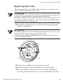
1
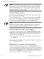
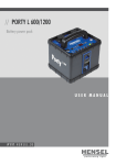
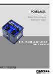
/
/
E
X
P
E
R
TD5
0
0/
D1
0
0
0
C
o
mp
a
c
t
f
l
a
s
hu
n
i
t
USER MANUAL/
/
23
22
21
1
20
19
2
Made in Germany
18
3
performing light
RC
AUDIO
FC
SLAVE
TEST
freemask
17
4
FULL
PROP
5
16
HENSEL
Profoto Air
6
15
7
8
14
13
12
9
10
11
F6
F7
F1
F2
F5
F3 F4
Strobe Wizard Plus / freemask
P1 P2 P3 P4
P1 P2 P3 P4
P14
P5
P13
P6
P12
P11
P7
P10
P9
P8
Profoto Air Remote
Profoto Air Sync
User Manual Expert D 500/1000
HENSEL-VISIT GmbH & Co. KG
Robert-Bunsen-Str. 3
D-97076 Würzburg-Lengfeld
GERMANY
Tel.
+49 (0) 931 27881-0
Fax:
+49 (0) 931 27881-50
E-mail:[email protected]
Internet:http://www.hensel.de
© HENSEL-VISIT GmbH & Co. KG, 2013
Distribution and reproduction of this documentation is not
permitted unless specifically authorized. In case of violation,
payment of damages will be due. All rights reserved, including
rights created by patent grant, or registration of a utility model
or design (ISO 16016).
Subject to technical changes. Errors and omissions excepted.
The listed data are standard values and not to be regarded as
guaranteed values in a legal sense. Values can deviate depending on component tolerance.
Effective date: 07/2013
4
HENSEL-VISIT GmbH & Co. KG
User Manual Expert D 500/1000
1 Preface
Dear photographer,
By purchasing the Hensel-Visit compact flash unit
Expert D 500/1000, you have selected a high-quality and
high performance product.
Below, we want to give you some details and hints on how to
use this unit. These will ensure successful and productive work
with it in the coming years.
Observing this necessary information entitles you to warranty
adjustments, prevents damages, and extends the operational
life of the unit.
Hensel-Visit took great care and observed all pertinent regulations in order to manufacture a safe product of highest quality.
Stringent quality checks ensure our high quality standard even
in large-scale production.
Please add your part and handle the equipment with the necessary care.
If you have any questions regarding the use of this equipment,
feel free to call us any time.
We wish you great success and „good light.”
HENSEL-VISIT GmbH & Co. KG
HENSEL-VISIT GmbH & Co. KG
5
User Manual Expert D 500/1000
2 Content
1Preface.............................................................................5
2Content............................................................................6
3 Safety instructions.............................................................8
4General.........................................................................11
Description................................................................11
Scope of delivery.......................................................11
5 Technical data................................................................12
6 Summary of control elements..........................................14
7 Initial use........................................................................15
Acclimatization..........................................................15
Removing transport cap.............................................15
Mounting/removing safety dome................................15
Inserting flash tube....................................................16
Inserting halogen lamp for modeling light...................16
Power supply.............................................................17
8Operation......................................................................19
Switch on/off.............................................................19
Modeling light...........................................................19
Performance output adjustment..................................20
Flash Check..............................................................20
Test flash...................................................................21
Flash readiness..........................................................21
Daily flash counter.....................................................21
Synchronization.........................................................21
PM mode (in connection with Power Max L).................22
9 Operation Strobe Wizard Plus..........................................24
6
HENSEL-VISIT GmbH & Co. KG
User Manual Expert D 500/1000
Summary of control elements.....................................24
Setting transmitter......................................................24
Setting receiver..........................................................25
Output adjustment.....................................................25
Switching the modeling light.......................................25
10Operation with freemask.................................................26
Settings for the freemask method................................26
11Operation with Profoto Air...............................................28
Basic functions...........................................................28
Summary of control elements.....................................29
Preparing transmitter.................................................29
Remote trigger...........................................................30
Remote control..........................................................32
12Maintenance..................................................................33
Regular maintenance.................................................33
Replacing fuses..........................................................33
Updating software.....................................................34
Replacing flash tube..................................................35
Replacing modeling light ...........................................36
Error messages..........................................................37
Warranty...................................................................38
Disposal....................................................................38
13Customer service points..................................................39
Manufacturer’s service...............................................39
Service points listed in the Internet..............................39
14Accessories.....................................................................40
15Subject index..................................................................41
16EU declaration of conformity...........................................42
HENSEL-VISIT GmbH & Co. KG
7
User Manual Expert D 500/1000
3 Safety instructions
In addition to the general rules for handling electrical equipment, the following safety precautions must be observed.
Read and observe the below listed information before initial
operation of the equipment.
Supply a copy of the safety precautions when selling, leasing, or
otherwise distributing this equipment.
ATTENTION!
Improper handling of the device, non-compliance with the safety
hints below, or tampering with the safety features can cause
property damage, bodily injury, electric shock, or even death.
Normal use
Abnormal use
The compact flash unit Expert D 500/1000 is intended for
professional use inside the studio. It is only to be used with the
accessories described in this manual and approved by HenselVisit.
The equipment may not be used for any other purpose than
described above, especially not for other electrical applications.
Set-up and initial operation
• Do not use flash units in explosive environments.
• Before connecting the equipment to the power supply, make
sure that the mains voltage corresponds to the specifications
listed on the unit’s specification plate.
• Compact flash units and generators must only be connected
to grounded power supply systems.
• Check the protective conductor function of the power supply
before initial use.
• Only use plugs/connectors with flawless contacts. Burned or
corroded plug contacts can cause fires. Defective plugs can
cause substantial damage to the plug socket.
• Do not connect accessories from other manufacturers, even
when these look similar or alike.
8
HENSEL-VISIT GmbH & Co. KG
User Manual Expert D 500/1000
• To prevent damages and tripping hazards, avoid laying
cables on the floor. If this is not possible, make sure that
the cables cannot be damaged by vehicles, ladders, etc.
• Damaged cables and housings need to be replaced immediately by an authorized service department.
• Keep the minimum distance around the equipment unobstructed to ensure proper ventilation.
• Keep core ducts unobstructed during operation to ensure
proper air supply.
• Do not insert objects into core ducts.
• Do not place any objects on top of the equipment (coffee
cups, vases, containers filled with water, etc.).
• Protect the equipment from moisture, dripping or splashing
water.
• Choose safe locations for set up and make sure that the
equipment cannot fall into pools or bodies of water. Never
Never run cables directly along or even through pools or
bodies of water.
• Keep proper distance from flammable materials like decorative fabrics or paper to prevent the risk of fire.
• Secure the equipment with a back-up support when attaching it to ceilings or pantographs. Use the tilt bracket’s
safety screw 11 and secure the device additionally with a
safety rope. Suitable safety ropes can be purchased from
Hensel-Visit, see „14 Accessories“ on page 40.
HENSEL-VISIT GmbH & Co. KG
9
User Manual Expert D 500/1000
Generators, compact flash units and flash heads
ATTENTION!
Defective flash tubes and false handling can pose a mortal
danger.
A damaged flash tube can mean mortal danger because you
could come in contact with the electrodes conducting high voltage. Therefore, never touch exposed electrodes inside the flash
tube!
Before replacing flash tubes or modeling lights, the unit must
be switched off and disconnected from the power supply or
the generator. Even when the unit is switched off and properly
disconnected from the power supply, the capacitor could still be
highly charged in case of a malfunction. This means touching
the device could pose a life-threatening danger.
Halogen lamps and flash tubes may burst and must only be
operated with properly mounted Hensel safety dome.
ATTENTION!
Contact with capacitor voltage can pose mortal danger.
Opening the housing or repairs of the unit must only be done by
an authorized customer service provider.
Working with the equipment
• Do not flash into eyes at short distances since this may lead
to eye damage.
• Do not look directly into the flash tube or the reflector. The
flash could be triggered accidentally.
• Regularly air closed rooms to prevent build-up of inadmissible ozone concentrations which can occur due to the use of
high-powered flash systems.
• Cover the equipment which is not in use with a proper dust
guard when working in a dusty environment.
10
HENSEL-VISIT GmbH & Co. KG
User Manual Expert D 500/1000
4 General
Description
The Expert D 500/1000 is a powerful compact flash unit. Extremely fast flash recycle times and short flash duration hallmark
this unit which can be used worldwide thanks to mulivoltage. A
bright, proportional modeling light which can be adjusted over
a wide 8 f-stop range, high-quality performance electronics
and the EH reflector connector are all housed in a solid housing
made from aluminum profiles and metal side panels.
A built-in radio receiver for Hensel Strobe Wizard Plus, freemask and Profoto Air allow full remote control of this unit’s
functions like triggering, output regulation, and modeling light.
This manual describes both compact flash units together,
Expert D 500 and Expert D 1000. The features and operation
are identical; the only difference is the performance. Please see
„5 Technical data“ on page 12.
Scope of delivery
Please check the scope of delivery before initial use.
Note:
The scope of delivery may vary depending on order configuration and country of delivery. Please see corresponding information on your delivery documents and order forms.
Standard scope of delivery includes:
• 1 Expert D 500 or 1 Expert D 1000
• 1 Flash tube, single-coated, plug-in type
• 1 Modeling light (according to customer requirement), included
• 1 Tilting bracket, combined with umbrella holder
• Cable set: mains and sync cord
• 1 Transport cap
• 1 User manual
HENSEL-VISIT GmbH & Co. KG
11
User Manual Expert D 500/1000
5 Technical data
Unit series/unit type
Expert D 500
Expert D 1000
Listed performance output:
500 J
1000 J
1 m = 90 0/10
2 m = 45 0/10
1 m = 128 0/10
2 m = 64 0/10
1/5.600 s
1/3.250 s
Lead aperture 100 ASA, t
1/60, 12“ reflector, 100%
output
1 m distance / 2 m distance :
Flash duration time (t 0,5 s) in
sec. up to:
Flash tube:
code no. 9450420:
plug-in style, single coated
Minimal recharge time:
0.11 s
0.14 s
Recharge time at 100% performance:
0.5 s
1.0 s
Flash performance adjustment:
10-3 = 8 f-stops
10-3 = 8 f-stops
Modeling light:
300W/G6.35/115V or 300W/G6.35/230V
Modeling light adjustment:
off / full / proportional / autored
Sync socket/ voltage:
6.3 mm jack plug, mono / 5 VDC
Fuses:
F 4 A H, 5 x 20 mm
Input voltage:
Multivoltage 110-240 V
Reflector connector:
quick-change automatic for EH (10 cm)
Weight:
ca. 3.4 kg
ca. 3.9 kg
Overall dimensions in cm:
LxWxH 35x13.1x19.7
LxWxH 38.5x13.1x19.7
Additional features:
thermical check of performance electronics
- Daily flash counter, reset
function:
yes
- Built-in fan:
yes
- Slave, switchable:
yes
- Flash check, switchable:
yes
- Modeling light stand-by:
autored
Technical modifications excepted.
The listed data are standard values which may deviate depending on component tolerances.
12
HENSEL-VISIT GmbH & Co. KG
User Manual Expert D 500/1000
Unit series/unit type
Expert D 500
Expert D 1000
- Internal power dump when
reducing output:
APD
- Glass safety dome:
yes
- Display:
7-segment for flash energy/daily flash counter/channel display/autored/Error code
- Control surface:
Code no.:
imprinted foil with keys, fluorescent, Hensel user logic
8350
8360
Technical modifications excepted.
The listed data are standard values which may deviate depending on component tolerances.
HENSEL-VISIT GmbH & Co. KG
13
User Manual Expert D 500/1000
6 Summary of control elements
1....... Slave on/off / PM mode on/off SLAVE
2....... Flash readiness indicator
3....... Flash trigger TEST
4....... Modeling light proportional PROP
5....... Display for set energy/channel indicator/flash counter
6....... Power switch
7....... Fuses and spare fuses
8....... Mains adapter socket
9....... Umbrella holder
10..... Locking screw tilting bracket
11..... Safety screw for suspended mounting
12..... Locking device stand mounting
13..... Storage of replacement fuses
14..... Locking device umbrella holder
15..... Mounting link for safety rope
16..... Digital rotary encoder for output adjustment/channel selection/group selection
17..... Modeling light FULL
18..... Radio receiver ON/OFF channel selection RC
19..... Audio signal ON/OFF AUDIO
20..... Flash Check FC
21..... USB interface
22..... Synchronization socket
23..... Slave
14
HENSEL-VISIT GmbH & Co. KG
User Manual Expert D 500/1000
7 Initial use
ATTENTION!
Please make sure that the unit is not connected to a power supply when preparing for initial use.
Acclimatization
When relocating the compact flash unit from and to locations
with substantial temperature differences, place the unit in the
surroundings where it is to be used and leave it there for some
time. This prevents moisture build-up which can result in creeping currents.
Removing transport cap
The transport cap protects the flash tube and the glass safety
dome during transport or when the unit does not have a reflector mounted.
ÂÂPress the locking mechanism of the reflector holder against
the spring tension until reaching the end stop.
ÂÂPull out the transport cap straight from the holder.
ATTENTION!
Do not switch on the flash unit with the transport cap attached.
This could pose a fire hazard due to the heat development of
the modeling light.
Mounting/removing safety dome
ATTENTION!
Please make sure the flash tube or modeling light is not damaged during mounting/removing.
Mounting
The safety dome snaps into place via three pre-installed
springs.
ÂÂTilt the safety dome slightly and insert it into one of the three
springs.
HENSEL-VISIT GmbH & Co. KG
15
User Manual Expert D 500/1000
ÂÂThen use gentle pressure to insert the safety dome first into
the second spring and then into the third spring until it locks
into place.
Removal
ÂÂTilt the safety dome slightly so that it is released one by one
from the mounting springs.
ÂÂPull the safety dome lightly from the third spring and remove it completely.
Note:
Safety domes are available in different types. They can change
the color temperature as well as the light characteristics!
Inserting flash tube
The compact flash unit has a plug-in flash tube, which you can
replace yourself. Please observe the applicable safety precautions carefully.
Inserting the flash tube is described in the chapter on maintenance, note „Replacing flash tube“ on page 35.
Inserting halogen lamp for modeling light
The modeling light has a plug-in halogen lamp. Insert the included halogen lamp by observing the following instructions:
Note:
Avoid touching the lamp with bare hands since this leaves an
oily residue on the glass surface which reduces the lamp’s operating life. Use cotton gloves.
Make sure that the flash tube does not become damaged
when inserting it.
ÂÂPlace the pins into the lamp socket and push the lamp carefully into place by alternating the pressure on the pins until
contacting the end stop.
ATTENTION!
Please regard the general safety precautions reference location
and surroundings in the chapter „Set-up and initial operation“
on page 8.
16
HENSEL-VISIT GmbH & Co. KG
User Manual Expert D 500/1000
The compact flash unit can be used in any position. Please note
that extremely tilted positions can lead to rapid warming of the
unit, especially in connection with narrow-angle reflectors. In
extreme cases, the result can be a thermal safety shut off!
Repositioning tilting bracket/handle
The position of the tilting bracket and the handle can be swapped. This lets you mount the flash unit in an overhead location
like a ceiling.
How to swap tilting bracket and handle:
ÂÂLoosen the two crosshead screws on the tilting bracket/
handle.
ÂÂSlide the tilting bracket/handle forward along the guide rail
of the housing.
ÂÂInsert the tilting bracket/handle into the guide rail on the
opposite side of the housing.
ÂÂTighten fast the two screws of the tilting bracket/handle.
Note:
Depending on the type of reflector attached, the position of
the tilting bracket/handle can be moved to the unit’s center of
gravity.
Power supply
ATTENTION!
Make sure that the power supply corresponds to the information on the type label/technical data sheet before connecting
the compact flash unit to the power supply. Compact flash units
must only be connected to a grounded power supply.
The type label is located at the bottom of the housing. The compact flash Expert D 500/1000 is solely approved for use with
115 V - 230 V / 50-60 hz operation.
It features multivoltage technology which means the unit automatically adjusts to the applicable voltage (110 V - 240 V).
HENSEL-VISIT GmbH & Co. KG
17
User Manual Expert D 500/1000
Fuse protection, building
Sockets intended for the connection of devices have to be protected with a minimum of 10 A.
Fuse protection, modeling light
The safety fuse 7 ensures the protection of the modeling light.
The compact flash unit Expert D 500/1000 is protected by a
4 A Fuse which reacts quickly (F 4 A H).
The listed safety values apply when the unit is used with a
300 W halogen lamp.
(Please note „Replacing fuses“ on page 33).
Fuse protection, flash unit
The inside of the unit contains a built-in fuse. This fuse responds when the unit is damaged.
ATTENTION!
Only authorized service centers may replace this fuse, see „13
Customer service points“ on page 39.
18
HENSEL-VISIT GmbH & Co. KG
User Manual Expert D 500/1000
8 Operation
Switch on/off
The main switch 6 switches the compact flash unit on or off. The
unit is ready to flash as soon as the ready indicator 2 lights up.
ATTENTION!
The power switch must be accessible and operational at all
times.
When turning on the unit, it defaults to the settings used last.
This means the unit „remembers“ the settings at switch-off.
Modeling light
The modeling light is switched on by using the key PROP 4 or the
key FULL 17. An LED above the key indicates the setting.
FULL: The modeling light is set at full power (300 W).
PROP: The light output (brightness) of the modeling light is proportional to the flash output.
Automatic modeling light reduction (Autored)
The compact flash unit’s modeling light is equipped with an
energy saving mode. After a preselected time, the light is
automatically reduced to level 9. When set on FULL mode, this
happens regardless of the selected flash output. When set on
PROP mode, this happens when the output setting is between
9.1 and 10. The default is set by the manufacturer at 35 min.
This conserves energy and extends the lamp’s operating life.
The original output is restored when you touch any key.
How to set the switch-off time:
ÂÂPress the digital rotary encoder 16 twice in fast sequence
(double-click).
The display 5 shows the selected switch-off time for ca. 3 s.,
e.g. A.35
ÂÂAdjust the time by turning the rotary encoder 16 in 1 minute
increments up to a maximum of 90 minutes.
A setting of „--“ causes the function to switch off.
HENSEL-VISIT GmbH & Co. KG
19
User Manual Expert D 500/1000
Normal operation is resumed automatically 5 sec. after last
using any control key.
Note:
Turning off the modeling light during longer breaks conserves
energy and expands the operating life of the lamp.
Performance output adjustment
The rotary encoder 16 adjusts the flash output in steps of 0.1
f-stops over an output range of 8 f-stops.
• Turning it clockwise increases the output in steps of 0.1
f-stops.
• Turning it counter-clockwise reduces the output in steps of
0.1 f-stops.
The LED display 5 shows the selected performance output values from 3.0 (lowest output) to 10 (maximum output).
When the performance output is reduced, the stored energy is
reduced via automatic power dump (APD function).
Note:
The power dump takes a moment. The flash readiness indicator 2 lights up to indicate restored flash readiness.
Flash Check
The Expert D 500/1000 is equipped with a visual flash readiness indicator called Flash Check. When this function is activated, the modeling light shuts off after flashing and turns on
again when the flash readiness is restored.
Activate or deactivate Flash Check with the FC key 1.
20
HENSEL-VISIT GmbH & Co. KG
User Manual Expert D 500/1000
Test flash
The key TEST 3 lets you trigger a test flash manually. Holding
down the key results in the fastest possible sequence of flashes.
Flash readiness
After switching the unit on, after flashing, and after adjusting
the flash output, flash readiness is indicated on a green LED 2
located above the TEST key 3.
Daily flash counter
The number of flashes triggered since last resetting the counter
is displayed on the LED display 5.
How to read the flash counter:
ÂÂPress the key AUDIO 19 for one second.
The number of flashes is shown in display 5.
The number range of the flash counter goes up to 999.
How to reset the daily flash counter:
ÂÂWhile in flash count mode, press the rotary encoder 16.
The display 5 is reset to 000.
Synchronization
Synchronization between compact flash unit and camera can
be optionally achieved via sync cord, the built-in slave, or a
built-in radio receiver.
Synchronization via cord
The compact flash unit is connected to the camera via sync
cord by connecting the 6.3 mm jack plug to the camera’s sync
socket.
The synchronization process uses the latest semiconductor technology and warrants reliable triggering of the flash unit even
when older camera models with mechanical contacts are used.
The lower voltage of the sync plug ensures safe and reliable
operation, also with the use of modern digital cameras.
HENSEL-VISIT GmbH & Co. KG
21
User Manual Expert D 500/1000
Note:
Based on a multitude of possible electronic circuits in different
cameras which are used for synchronization, we are not liable
for possible damages to the camera used for flash triggering.
Please contact the camera’s manufacturer before using a nonstandard camera for such purpose.
Synchronization via slave
The built-in slave 23 triggers the flash when light from another
flash is detected (slave mode).
This mode of operation is activated/deactivated with the SLAVE
key 1. The active setting is indicated via LED above the key.
The slave is an impulse photo cell. It only triggers the flash
when the striking light is brighter than the ambient light.
Note:
Make sure that other bright, ambient light does not reach the
photo cell. If this cannot be avoided, please use a cable or
radio transmitter for synchronization.
Synchronization via radio remote trigger
The optional radio remote triggers Strobe Wizard Plus, freemask and Hensel Profoto Air are used to conveniently synchronize the camera and flash unit via radio remote control. See
„14 Accessories“ on page 40.
ÂÂIn this set-up, you have to switch off the slave function with
the SLAVE key 1.
How to operate with optional radio remote triggers is described
in the following chapters.
PM mode (in connection with Power Max L)
Hallmarks of the compact flash units of the Expert D series
are their especially short flash duration times and fast recycling
times - also when operated with a Power Max L. This results in a
comparatively high power draw. In order to guarantee optimum
functioning, the Expert D must be switched to a special mode
when used in connection with a Power Max L.
22
HENSEL-VISIT GmbH & Co. KG
User Manual Expert D 500/1000
In this mode, the modeling light is set to 100W and the „Flash
Check“ function, which turns off the modeling light after flashing and turns it back on as soon as the unit has recharged
and is ready to flash again, is activated.
ÂÂConnect the Expert D compact flash unit to one of the power jacks on the Power Max L and switch the Power Max L on
via the power switch.
ÂÂSwitch on the Expert D and press its SLAVE button for at
least 3 seconds: the flash unit now switches to the Power
Max mode which is then confirmed by a beep tone. The
selected output and „bat. “ blink alternately in the performance display to indicate the activated Power Max mode.
Additionally, the LED „FULL“ blinks on the flash unit indicating that the modeling light is dimmed to a fixed, nonproportional 100W.
ÂÂAfter connecting and switching the first Expert D, you can
add – if needed – a second unit and also switch it to the
Power Max mode as indicated above.
The Expert D flash units stay in this mode once it is activated, even after they are switched off. No damage occurs if the
Expert D are operated on a normal power supply when in
Power Max mode. To return to a full modeling light, the SLAVE
button must be pressed again for 3 seconds – the Power Max
mode is deactivated.
ATTENTION!
Expert D flash units prior to serial number 1303H0030101340
(Expert D 500) and 1303H0030100461 (Expert D 1000) do not
function in connection with the Power Max L and need a new
operating software.
Please contact your Hensel service at the Wuerzburg headquarters and have the update done there.
NOTE: We recommend turning off the modeling light when
using Expert D flash units connected to the Power Max L to
achieve highest flash capacity.
HENSEL-VISIT GmbH & Co. KG
23
User Manual Expert D 500/1000
9 Operation Strobe Wizard Plus
Radio triggering
Radio remote
control
The compact flash unit has a built-in radio receiver that can be
used for flash triggering.
This radio connection also allows you to remotely control the
modeling light.
Summary of control elements
Transmitter
F1...... Control key q (flash energy and modeling light options)
F2...... Control key p (flash energy)
F3...... Fixing nut for mounting on hot shoe
F4...... Test flash trigger
F5...... Channel selection switch
F6...... Mounting eye/locking screw for battery compartment
F7...... Socket for sync cord 2.5 mm
Setting transmitter
Mounting transmitter
The transmitter does not have an ON switch. It is ready when
connected to the camera via the hot shoe or a sync cord.
ÂÂAttach the transmitter to the hot shoe of the camera and
secure it with the fixing nut F3.
- or ÂÂDepending on camera type, mount the transmitter to a flash
rail and connect the transmitter socket F7 to the camera via
the included sync cord.
Setting channel
24
Transmitter and receiver can be synchronized via three different
channels. Up to three different work stations can be controlled
separately. Additionally, the transmitter can also control all
receivers together.
The setting is done via the F5 key.
HENSEL-VISIT GmbH & Co. KG
User Manual Expert D 500/1000
ÂÂSet the channel selection switch F5 to channel 1, 2 or 3.
- or ÂÂSelect the switch position ALL when all channels are to be
controlled.
Setting receiver
The key RC 18 on the flash head is used to activate the radio
receiver and to set the channel.
ÂÂBriefly press the key RC 18 until the LED above the key lights
up green, or press the digital rotary encoder 16.
Selecting radio
channel
ÂÂPress the key RC 18 for ca. 2 s to switch the channels of the
radio receiver.
The display 5 is now blinking and shows the set channel,
e.g. H.C1 for the first channel of Strobe Wizard Plus.
ÂÂTurning the rotary encoder 16 within 3 s lets you set the desired channel.
After the channel „C1“come the channels „C2“and „C3“of Strobe Wizard Plus, directly after them the channels „F1“, „F2“ and
„F3“ of the freemask receiver.
Approximately 3 s after a key was last pressed, the channel is
saved and the display 5 stops blinking.
Output adjustment
The flash output is adjusted in steps of 0.1 f-stops with the two
control keys q F1 and p F2 on the flash unit.
ÂÂBriefly press q to reduce the output.
ÂÂBriefly press p to increase the output.
The compact flash unit’s LED display shows the selected output
values.
Switching the modeling light
Pressing the q key F1 longer (< 1 sec.) switches on the modeling light of the connected flash head. Depending on the connected flash head, the modeling light can be set to OFF – FULL
– PROP – OFF.
HENSEL-VISIT GmbH & Co. KG
25
User Manual Expert D 500/1000
10 Operation with freemask
The transmitter „freemask“ has all the functions of the Strobe
Wizard Plus and is operated the same way. Output adjustment
via the transmitter can only be done in the „C“-channels, not in
the „F“ channels.
Additionally, the transmitter is used for the freemask method.
„freemask“ is a photographic method to produce digital clipping masks. For this method, the camera takes two exposures
in sequence. Exposure values and camera position remain unchanged for both exposures. The freemask transmitter controls
the two flash groups used for both exposures:
• The flash group for the actual motif to be photographed.
• The flash group for the backlighting-like background lighting (mask lighting).
A mask layer is easily created with the help of image editing
and thus the motif can be extracted.
The flash unit has three other „F“ channels besides the standard
„C“ channels for this.
• The flash units for lighting the motif are assigned to the „C“
channels.
• The flash units for the lighting the background to be masked
are assigned to the „F“ channels.
When selecting channels, (see „Setting receiver“ on page 25)
the freemask receiver channels „F1“, „F2“ and „F3“ come
after the Strobe Wizard channels „C1“, „C2“ and „C3“, e.g.
H.F1 for the first channel.
Settings for the freemask method
Settings for one work station
freemask transmitter
ÂÂSet the channel selector switch F6 to All or the selected channel.
Motif lighting
ÂÂSet all flash units for the motif lighting on „C“ channels (C1,
C2, C3).
26
HENSEL-VISIT GmbH & Co. KG
User Manual Expert D 500/1000
Mask lighting
ÂÂSet the compact flash unit for the mask on „F“ channels (F1,
F2, F3).
Note:
In this case, the slave of the Expert D 500/1000 needs to be
switched off with the SLAVE key 1 to prevent triggering the first
group of flashes. All other slaves can be switched on.
Camera
ÂÂSet the camera on fastest possible continuous shooting
speed.
ÂÂSet the number of exposures to „2“ if your camera supports
this.
This guarantees the highest exposure frequency setting with two
consecutive exposures (depending on camera).
The transmitter will trigger the flash group needed for lighting
the motif (C1, C2, and C3) and then trigger the flash group
needed for lighting the mask (F1, F2 und F3).
Currently, all cameras support exposure series speeds from 3
pictures per second to (in theory) 500 exposures per second.
Settings for several work stations
If several separate work stations (up to 3) exist within a radio
range, each work station must have a channel assigned to it.
ÂÂSet the channel selection switch F6 on 1, 2, or 3.
ÂÂAssign the same „C“ channel to lighting the motif.
ÂÂAssign the same “F” channel to lighting the mask.
Example:
station 1: transmitter channel 1 station 2: transmitter channel 2 station 3: transmitter channel 3 HENSEL-VISIT GmbH & Co. KG
motif C1
motif C2
motif C3
mask F1
mask F2
mask F3
27
User Manual Expert D 500/1000
11 Operation with Profoto Air
Profoto Air
Sync
Profoto Air
Remote
The compact flash unit is equipped with a built-in radio receiver
for Profoto Air radio remote controls. The Profoto Air system is
available in two versions:
This unit allows you to trigger individual flash units via 8 channels.
This unit allows you to synchronize, adjust flash output, and
remotely control the modeling light.
Furthermore, the Profoto Air units have additional options which
can be used to control flash units and cameras without integrated Profoto Air receiver.
Basic functions
Channels
Groups
Profoto Air Sync/Remote units transmit via 8 different channels.
The Expert D 500/1000 has 8 Profoto channels. Work at 8
different stations is possible without interfering with each other.
Additionally, the Profoto Air Remote and the
Expert D 500/1000 include the option of assigning the units to
be triggered to up to 6 groups and then control these jointly.
• All flash units assigned to the same group are controlled
together.
• Several generators/compact flash units can be assigned to
one group.
• In master mode, all compact flash units assigned to the
same channel can be controlled regardless of their group
assignment.
Note:
For additional information about the multitude of Profoto Air unit’s functions and how to use them, please see the
manufacturer’s applicable operating manual.
28
HENSEL-VISIT GmbH & Co. KG
User Manual Expert D 500/1000
Summary of control elements
P1...... Channel selection key CHANNEL
P2...... Mode transmitter/receiver MODE
P3...... Test flash flash/camera TEST
P4...... On/off key ON
P5...... Flash output increase ENERGY +
P6...... Flash output reduction ENERGY P7...... Group selection key GROUP
P8...... Modeling light ON I
P9...... Modeling light OFF O
P10.... Select all groups MASTER
P11.... Synchronization socket flash OUT
P12.... Synchronization socket camera IN
P13.... Flash head off O (standby On)
P14.... Flash head on I
Preparing transmitter
Mounting transmitter
The transmitter has a hot shoe adapter. The camera is synchronized via this or a separate cable.
ÂÂAttach the transmitter to the camera’s hot shoe.
- or ÂÂConnect the transmitter’s socket P12 IN to the camera with
the included sync cable.
Switching transmitter on/off
ÂÂSwitch the transmitter on by pressing the P4 ON key.
The LEDs are blinking and show the current settings.
ÂÂPress the P4 ON again to turn the transmitter off.
The transmitter turns off automatically after 30 minutes of inactivity.
HENSEL-VISIT GmbH & Co. KG
29
User Manual Expert D 500/1000
Transmitter/receiver mode
Profoto Air Sync/Remote units can either be used as a transmitter or as a receiver.
ÂÂPress the P2 MODE key until the LED TRANSMIT lights up.
This sets up the unit as a transmitter.
- or ÂÂPress the P2 MODE key until the LED RECEIVE lights up.
This sets up the unit as a receiver.
Remote trigger
Channels
The transmitter has 8 different channels for synchronizing flash
heads. The compact flash unit has 8 Profoto Air channels. This
lets you control up to 8 work stations separately.
Channel setting
Transmitter
Expert D
500/1000
All units that are supposed to work together need to be set on
the same channel.
The setting is done with the channel selection key P1.
ÂÂPress the channel selection key P1 until the desired channel
1-8 is indicated on the LED bar.
The Profoto Air channels of Expert D 500/1000 are designated with P1- P8 and are shown on display 5, e.g. P.1A for
channel 1 and group A.
ÂÂBriefly press the RC key 18 several times until the LED above
the key lights up orange.
ÂÂPress the RC key 18 for ca. 2 s to change the channels of the
radio receiver or press the digital rotary encoder 16.
The display 5 is now blinking and shows the set channel,
e.g. P.1A for channel 1 and group A of Profoto Air.
ÂÂSet the desired channel by turning the digital rotary encoder
16 within 3 s.
30
HENSEL-VISIT GmbH & Co. KG
User Manual Expert D 500/1000
Setting group
Transmitter
The group setting lets you combine individual flash heads. This
allows you to jointly control the settings of the flash heads contained in this group.
Triggering of the flash heads is done via the channel assignment. Additionally, the transmitter can control all groups together (master mode).
The setting is done with the P7 key.
ÂÂPress the group selection key P7 until the desired group is
shown in the LED bar.
- or ÂÂPress the MASTER key P10 to select all groups.
The complete LED bar lights up and all flash heads with the
same channel are controlled regardless of group assignment.
Expert D
500/1000
The compact flash unit can be individually assigned to a group.
The selected group (letter A-F) is shown in display 5.
How to change the flash channel’s group assignment:
ÂÂPress the RC key 18 for ca. 2 s or press the digital rotary
encoder 16.
The display is now blinking.
ÂÂSet the desired group (A to F) by simultaneously pressing
and turning the digital rotary encoder 16 within 3 s.
After 5 s the display returns to its former setting and shows the
selected performance output.
Checking channel/group assignment
ÂÂPress the RC key 18 for ca. 2 s or press the digital rotary
encoder 16.
The display 5 is now blinking and shows the channel and
the group.
HENSEL-VISIT GmbH & Co. KG
31
User Manual Expert D 500/1000
Remote control
Setting power output
The keys P5 +and P6 – are used for adjusting the flash output
ENERGY of the controlled flash unit. Briefly pressing the key adjusts the power in steps of 0.1 f-stops, pressing the key longer
(> 2 s) adjusts the power in full f-stop steps.
ÂÂPress P5 +to increase the power
ÂÂPress P6 – to decrease the power
The generator’s LED display shows the set output values.
Flash head on/off
The controlled flash unit can be switched on and off via the
keys P13 and P14.
ÂÂPress P13 to switch off the flash heads assigned to the group
Standby on, a dot in the display lights up.
ÂÂPress P14 to switch on the flash unit assigned to the group.
Setting the modeling light
The controlled flash heads’ modeling lights Model can be switched on and off on the generator via the keys P8 and P9.
ÂÂPress P8 to switch on the modeling light.
ÂÂPress P9 to switch off the modeling light.
32
HENSEL-VISIT GmbH & Co. KG
User Manual Expert D 500/1000
12 Maintenance
ATTENTION!
The compact flash unit must be switched off and disconnected
from the power supply before doing any maintenance work to it.
The compact flash unit Expert D 500/1000 requires little user
maintenance.
To guarantee the electrical safety, the outside of the unit must
be cleaned regularly from dust and dirt.
Note:
Only clean the unit dry!
Regular maintenance
National safety regulations require the maintenance and inspection of any electrical system and equipment in regular intervals. Compact flash units, generators, and accessories must be
inspected at regular intervals to ensure operational safety. An
annual inspection of such equipment ensures the user’s safety
and retains equipment value.
Replacing fuses
ATTENTION!
Fuses must not be „patched up“ or otherwise bypassed. Only
use spare fuses that match the below listed value and have the
response rating ”fast”.
The compact flash unit must be switched off and disconnected
from the power supply before replacing the fuse.
Safety fuses for operation with 300 W halogen lamp: F 4 A H,
5x20 mm.
Only use fuses with „high switching capacity“, type “H”, according to EN 60127-2/1 or IEC 127-2/1. The wrong safety fuse
can increase the danger of the halogen lamp bursting in case
the coiled filament melts.
HENSEL-VISIT GmbH & Co. KG
33
User Manual Expert D 500/1000
How to replace a fuse:
ÂÂOpen the safety drawer 7 with a small screwdriver and pull
it out.
7
b
a
Note:
The drawer can only be pulled out approximately 1 cm.
Inside the drawer are two fuses. The rear fuse a is an active
fuse, the front fuse b is a spare fuse.
ÂÂRemove the defective fuse a.
ÂÂTake out the spare fuse b and insert it into the rear holder.
ÂÂCarefully push the drawer back into the housing until it
locks into place.
Note:
The handle of the compact flash unit contains additional spare
fuses 13.
Replace spare fuses after removal und insert them into the proper space.
Updating software
If necessary, the compact flash unit’s software can be updated
via the USB interface 21 located on the top side of the housing.
ÂÂContact your customer service center, see „13 Customer
service points“ on page 39.
34
HENSEL-VISIT GmbH & Co. KG
User Manual Expert D 500/1000
Replacing flash tube
The compact flash unit’s flash tube is plug-in. In case of a defect, it can be replaced by the user.
ATTENTION!
Switch off the unit and wait at least 15 minutes for the capacitor
voltage to deplete before replacing the flash tube.
Avoid touching the flash tube with bare hands to prevent its contamination with oily residue. This would reduce the flash tubes
operating life. Use cotton gloves.
ÂÂRemove the safety dome, see „Mounting/removing safety
dome“ on page 15.
ATTENTION!
Should the glass body of the flash tube be broken, do not touch
the electrodes while replacing the flash tube!
In this case, use fully insulated pliers to unwind the wire and
remove the flash tube!
D
0,5
mm
A
C
B
ÂÂUnwind the wire B from the connecting pin C.
ÂÂCarefully pull the flash tube A from the plug base D.
ÂÂPlace a suitable, new flash tube on the plug base D and
carefully push the flash tube in until reaching the end stop.
HENSEL-VISIT GmbH & Co. KG
35
User Manual Expert D 500/1000
ÂÂPull the flash tube out again approximately 0.5 mm so that
the glass body can expand upon warming.
ÂÂWrap the wire B onto the connecting pin C.
Suitable flash tubes for compact flash unit Expert D 500/1000,
see chapter „14 Accessories“ on page 40.
Replacing modeling light
The halogen lamp of the compact flash unit’s modeling light is
plug-in. In case of a defect, it can be replaced by the user.
ATTENTION!
Before replacing the halogen lamp, switch off the unit and disconnect it from its power supply. Wait at least 15 minutes for the
halogen lamp to cool off.
Avoid touching the flash tube with bare hands to prevent its contamination with oily residue. This would reduce the flash tubes
operating life. Use cotton gloves instead.
ÂÂRemove the safety dome, see „Mounting/removing safety
dome“ on page 15.
ÂÂCarefully pull the lamp from its plug connector.
ÂÂInsert a suitable lamp.
Ensure that the lamp is fuse protected according to regulation,
see „Replacing fuses“ on page 33.
Maximum modeling lights to be used are:
300W/G6.35/115V resp. 300W/G6.35/230V
The modeling light has to match the voltage of the power supply.
36
HENSEL-VISIT GmbH & Co. KG
User Manual Expert D 500/1000
Error messages
In case of an error, an error code is shown in display 5. In this
case proceed as follows:
ÂÂSwitch off the unit.
ÂÂWait a few seconds.
ÂÂSwitch the unit on again.
If the error code persists, check if the problem can be remedied
according to the following list or contact customer service and
state the error code, see „13 Customer service points“ on page
39.
Error E4
Unit does not flash.
If several units are on the set, the misfiring of individual units is
shown in the display.
Possible causes can be a spent flash tube or an internal equipment problem.
ÂÂYou may need to replace the flash tube or send the unit in
for service.
This error message disappears on its own after a short period
of time.
Error E5
Unit is overheated.
In case of this problem, the modeling light shuts off and the
unit stops flashing.
Possible causes can be extensive flashing, high ambient temperatures with full modeling light, covered core ducts, unsuitable
reflectors or a defective fan (check by listening).
ÂÂKeep the unit switched on so that the fan continues to cool
the flash unit.
Remedy or improve the situation by switching off the modeling light.
The error message disappears once the unit has cooled off.
HENSEL-VISIT GmbH & Co. KG
37
User Manual Expert D 500/1000
Error
Error
Error
Error
E1
E2
E3
E6
Internal faults of unit.
These error codes signify substantial errors. These problems
can only be fixed by customer service.
ÂÂSwitch off the unit immediately and remove it from the set.
ÂÂSend the unit to the nearest customer service with indication
of the error code.
Warranty
The warranty period for the compact flash unit
Expert D 500/1000 depends on the country of delivery.
You can obtain information pertaining to warranty periods on
the Internet pages of the distributing companies.
Normal usage, meeting the safety requirements in the instruction manual, and adhering to the information therein are
prerequisites for this warranty. Unauthorized manipulation and
tampering with the unit void any warranty claim.
Flash tubes, modeling lamps, protective glass covers, and
defective cables which are caused by improper handling are
excluded from the warranty.
The warranty includes replacement of faulty parts and the time
required for installation by a qualified technician.
Note:
You may send the unit free of charge to one of the customer
service points, see „13 Customer service points“ on page 39.
Please include a short description of the defect.
Disposal
The packing material of the compact flash unit needs to be sorted and recycled as necessary. Retired and defective electronic
equipment must be recycled in accordance with regulation.
38
HENSEL-VISIT GmbH & Co. KG
User Manual Expert D 500/1000
13 Customer service points
Manufacturer’s service
HENSEL-VISIT GmbH & Co. KG
Robert-Bunsen-Str. 3
97076 Würzburg
Tel.: +49 (0)931 278 810
Fax: +49 (0)931 278 815 0
E-Mail: [email protected]
Service points listed in the Internet
Additional national and international service and distribution
addresses can be found on the web page of Hensel-Visit
GmbH & Co. KG: www.hensel.de
HENSEL-VISIT GmbH & Co. KG
39
User Manual Expert D 500/1000
14 Accessories
Safety dome
clear, uncoated
clear, single-coated
matt, uncoated
code no.: 9454638
code no.: 9454637
code no.: 9454639
Flash tube
Expert 500 plug-in, single-coated code no.: 9450420
Expert 1000 plug-in, single-coated code no.: 9450420
Halogen lamp for modeling light
300 W/230 V
300 W/115 V
code no.: 128
code no.: 1280
Reflectors and softboxes
With small connector diameter (10 cm) for the EH/Expert/
Integra unit series
Replacement fuses
Safety fuses F 4 A H
code no.: 9412400
Radio trigger
Strobe Wizard Plus transmitter Strobe Wizard Plus receiver freemask transmitter Profoto / Hensel Air Sync
Profoto / Hensel Air Remote
code no.: 3950
code no.: 3951
code no.: 3955
code no.: 3965
code no.: 3966
Additional accessories
Safety rope code no.: 7690
Sync cord, various lengths
Umbrellas
Additional information about accessories can be found on the
Internet page of HENSEL-VISIT GmbH & Co. KG:
www.hensel.de
40
HENSEL-VISIT GmbH & Co. KG
User Manual Expert D 500/1000
15 Subject index
A
O
APD function 20
Autored 12, 19
Output adjustment 20, 25, 26
C
Control elements 14, 24, 30
Power supply 10, 15, 17, 33, 36
Profoto Air 22, 30
D
R
Daily flash counter 12, 21
Radio remote trigger 22
E
S
Error message 38
Safety dome 10, 13, 15, 40
Safety fuse 18, 33, 40
Scope of delivery 11
Set-up 8
Slave 12, 21, 22, 27
Strobe Wizard Plus 22, 24, 26, 40
Synchronization 21
F
Flash check 20, 23
Flash group 26, 27
Flash readiness 20, 21
freemask 22, 26
Fuse 12, 18, 33, 36, 40
H
Halogen lamp 16, 18, 33, 36, 40
P
T
Test flash 21, 24, 29
Tilting bracket 11, 17
M
Modeling light 10, 11, 12, 16, 18,
19
HENSEL-VISIT GmbH & Co. KG
41
User Manual Expert D 500/1000
16 EU declaration of conformity
about electro-magnetic compatibility and electrical safety
42
HENSEL-VISIT GmbH & Co. KG
User Manual Expert D 500/1000
Notes
HENSEL-VISIT GmbH & Co. KG
43