1
DINION imager 9000 HD
3.4
Installation | en
21
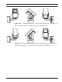
Mount the Junction Box
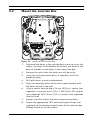
Figure 3.4
1.
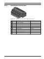
Interior of the Junction Box
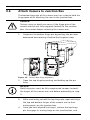
Decide which holes in the junction box to use to insert the
cables: the holes in the bottom of the box, the holes in the
back of the box, or the holes in the side of the box.
2.
3.
Remove the seals from the holes you will be using.
Using the wall mount bracket as a template, mark the
mounting holes.
4.
5.
Drill pilot holes at each marked point.
Align the mounting holes of the wall mount bracket with
the holes drilled in the wall.
6.
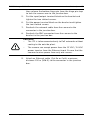
Using a socket wrench and a 14 mm (9/16 in.) socket (not
supplied), screw the first 1/4-9 x 2 (M7-0.35 x 50) lag bolt
(not supplied) with 12 mm (1/2 in.) washer (not supplied)
into the stud.
7.
8.
Repeat step 8 to attach the three remaining lag bolts.
Attach the appropriate NPS watertight pipe fittings (not
supplied) to the bottom or back holes of the junction box
through which to run the cables.
Bosch Security Systems
Installation manual
AM18-Q0663 | 1.0 | 2013.09