1
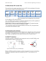
Name: Omar Jones Course: Electronics Engineering, Final year (3) 4.1.4-Timer/Counter Control register In this case an increment needs to be done to use 10-bit instead of 8-bit. There are three TCCR (Timer/Counter Control Register), could be modified to the specific mode and bits in the A channel (TCCRnA). Timer/Counter Control Register TCCR0B - TCCR0A TCCR1B - TCCR1A TCCR2B - TCCR2A Pin number (Arduino) 5 6 9 10 3 11 Table3, TCCR It’s obvious that the change in Timer/counter bit quantity effect the frequency, so if we want to change it then the prescaler has to be changed. TCCR = system_clock / prescaler_value. The frequency could be changed by changing specific bits in the B channel (TCCRnB) Controller Registers the, bits and Wave Generation Mode to meet the required behavior to pair/pairs of pins, www.atmel.com. It’s not possible though to specify different frequency for each pin though, whereas a Timer/Counter setting applies the concerned two pins. Nevertheless, there are three pairs that could have three different frequencies. Basically, there are only two Timers/Counters that have been changed in this project. Since we need to set pin 5 to write 10-bit for the moment, then pin 5:6, TCCR0A and TCCR0B have to be modified. An explanation of this modification is illustrated in the following way: TCCR0A Bit 7 6 5 4 TCCR0A Com1A1 Com1A0 Com1B1 Com1B0 Read/Write R/W R/W R/W R/W Initial value 0 0 0 0 3 R 0 2 R 0 1 0 WGM11 WGM10 R/W R/W 1 1 Table4, TCCR0A Bit 7:4 are Compare output Mode for Channel A&B; we are only interesting in fast PWM mode. Bit 3:2 are reserved. Bit 1:0 Wave Generation Mode, these bits with combination with WGM13:12 bits (see table 5, TCCR0B) modifies the type of generation mode. Mode WGM13 WGM12 WGM11 WGM10 7 0 1 1 1 Table5, Fast PWM mode, 10-bit 16 Timer top HEX 0x03FF Top Timer (Decimal) 1023