1
Institutionen för systemteknik
Department of Electrical Engineering
Examensarbete
DESIGN AND DEVELOPMENT OF AN EMBEDDED DC MOTOR CONTROLLER
USING A PID ALGORITHM
Examensarbete utfört i Elektronik
av
Omar Jones
Omar Jones
LiTH-ISY-EX--10/4417--SE
Linköping 2010-06-15
TEKNISKA HÖGSKOLAN
LINKÖPINGS UNIVERSITET
Department of Electrical Engineering
Linköping University
S-581 83 Linköping, Sweden
i
Linköpings tekniska högskola
Institutionen för systemteknik
581 83 Linköping
Name: Omar Jones
Course: Electronics Engineering, Final year (3)
DESIGN AND DEVELOPMENT OF AN EMBEDDED DC MOTOR CONTROLLER
USING A PID ALGORITHM
Examensarbete utfört i Elektronik
vid Linköpings tekniska högskola/London South Bank University
av
Omar Jones
LiTH-ISY-EX--10/4417--SE
Linköping/London 2010-06-15
Handledare: Goran Bezanov, London South Bank University
Examinator: Jonny Lindgren, Linköping universitet
ii
Name: Omar Jones
Course: Electronics Engineering, Final year (3)
Institution, Avdelning
Division, Department
Datum 2010-06-15
Date
Division of Electronic Systems
Department of Electrical Engineering
Link¨opings universitet
SE-581 83 Linköping, Sweden
Språk
Rapporttyp
Language
Report category
ISBN
Svenska/Swedish
Licentiatavhandling
ISRN
LiTH-ISY-EX--10/4417--SE
Engelska/English
Examensarbete
Serietitel och serienummer
C-uppsats
Title of series, numbering
D-uppsats
¨Ovrig rapport
Titel Kontrol av DC-Motor i enbyggda system med hjlp av PID & PWM
Title DESIGN AND DEVELOPMENT OF AN EMBEDDED DC MOTOR CONTROLLER USING A PID ALGORITHM
Författare Omar Jones
Author
Sammanfattning
Abstract
Projektet utfördes på engelska vid London South Bank University. Rapporten syfter på användning av metoder
och tekniker som minimerar kostnader och tid.
Med hjälp av ATmega328 mikrokontroller kan man styra en DC-motor i closed loop hantering.
Nyckelord
PID, PWM, thermometer feedback sensor, potentiometer Setpoint, Brushless DC-Motor, AD/DA Converter
iii
Name: Omar Jones
Course: Electronics Engineering, Final year (3)
Abstract
This project was held at London South Bank University in the UK, with corporation
with staff from Linköping University in Sweden as Bachelor thesis.
This report will guide you through the used techniques in order to achieve a
successful cooler/Fan project with a minimum budget and good energy saving
methods.
The steps of setting the used software and components are supported with figures
and diagrams. You will find full explanation of the used components and
mathematics, in additional to a complete working code.
iv
Name: Omar Jones
Course: Electronics Engineering, Final year (3)
Summary
A PID controller has been used in order to regulate particular closed loop systems.
Digital implementations have also been used in many applications to reduce costs
and time and to get better results compared with the corresponding analogue
solutions.
The project implements a PID controller using the 8051 family Microcontroller family
as a processing element. ATmega328 microcontroller will be used in an embedded
application so that it will process signal inputs and deliver suitable signal outputs
based on a designed and implemented PID control algorithm in IDE (Integrated
Development Environment).
Mainly, the microcontroller will read from inputs the required temperature and
feedback of the current temperature from a thermometer sensor.
The output will be control the speed of a DC motor, which is a fan in this case.
The speed of the fan controlled via a NPN transistor, which in its turn will be driven by
chains of digital signals (Puls Width Modulation).
The calculation of the implied output signal is explained regarding theories such as;
PID and PWM. Also a brief illustration of setting Timers/Counters of the intended
8051 microcontroller family is included.
v
Name: Omar Jones
Course: Electronics Engineering, Final year (3)
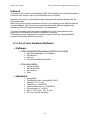
Index
1.1 Introduction……………………………………………………………………………………1
1.2 Aim…………….………………………………………………………………………………..2
2.1 Objectives .……………………………………………………………………………………3
2.2 Deliverables…………… ………………………………………………………………….…3
2.3 Requirements….……………………………………………………………………………..4
Technical Background and Context
3.1 PID ………………………………………………………………………5
3.2 PWM…………………………………………………………………………...6
4-Technical_Approach………………………………………………………………………….7
4.1.1- Software ………………………………………………………………………………….8
4.1.2-Arduino ……………………………………………………………………..9
4.1.3-Writing_the_code………………………………………………………..10
4.1.4-Wiring_Code/Scaling………………………………………………...10-15
4.1.5-TCRR Timer/Counter Control registers ……………………...16-17
4.2.1- Hardware_Core…………………………………………………………………..…….18
4.2.2-Freeduino_SB v2.2 ……………………………………………..……....18
4.2.3-ATmega328_AND_8051 Family comparison ……………..……....19
5-Hardware_Components …………………………………………………………………....20
5.1-LM35DH_Temperature_Sensor …………………………………….….20
5.2- Brushless DC_Motor_Fan …………………………………………...…21
5.3-POTentiometer (knob) ………………………………….........................21
5.4-BJT Transistor ………………………………………………………..…....22
5.5-The_Project …………………………………………………………..…….22
6-Result…………………………………………………………………………………..……….23
6.1-List ……………………………………………………………………………23
7-Porject_Planning …………………………………………………………………………….24
8-References ……………………………………………………………………………………25
9-Appendex ……………………………………………………………………………………..26
9.1-VBB ………………………………………………………………………….26
9.2-Code …………………………………………………………………….27-29
9.3-Project Photos …………………………………………………………….30
9.3.1-Soldering_Freeduino ……………………………………………..31
9.3.2-Project_test …………………………………………………………31
9.3.3-After some Enhancements ………………………………………32
vi
1.1-Introduction
The system designed with emphasis on embedded solution, using PID control and
digital signals to control a DC motor speed.
Several IDE were used in order to implement the microcontroller.
Furthermore three different microcontroller of 8051 family have been tested as well.
The microcontroller will read analog signals from:
a) Temperature sensor as feedback.
b) Potentiometer (Knob) as Setpoint control.
The output will be delivered as digital signal in order to control the speed of the DC
motor (Fan). The applied technique of controlling the motor is PWM (Puls Width
Modulation) will adjust the analog device via a transistor.
The Setpoint input to the microcontroller will be an analogue potentiometer regulator
which will set a particular temperature degree in the scale of (10-25) °C; this could be
changed if desired.
The feedback to the input will be received from a temperature sensor then the PID
control will compare the result of both inputs to generate the suitable puls to the
fan/cooler (DC-motor).
This program has been written using Wiring-language in Arduino software to load it
later to the Freeduino/Arduino hardware to run the application.
Furthermore, the hardware part is quite simple to follow, which is the purpose of
using the embedded system.
Nevertheless, the report will guide the reader through the experimental process of the
approaches, whereas many issues have formed this project is.
1
Name: Omar Jones
Course: Electronics Engineering, Final year (3)
1.2-Aim
The project is aimed to develop an embedded DC Motor controller using PID
controller on ATmega328 microcontroller.
The Digital PID control has been initialized in a structure of programming the
microcontroller via USB using Wiring programming language in Arduino software.
Basically the program takes the desired temperature and feedback from temperature
sensor as inputs and calculates the Duty Cycle by PID controller algorithms to deliver
a suitable power to the fan as an output.
The progress of the project has been divided mainly in two parts, the software part
which includes the programming of the microcontroller and the hardware part; the
sensor, the fan, the knob and Arduino.
To get an acceptable output to the DC motor, which runs regarding to the applied
temperature, the code of this process has been simulated on Arduino, although the
simulation gave no accurate results as expected, thus it needed actual testing.
The synchronizations of the different operations have been calculated in the
microcontroller, but to get a suitable output an experimental progress gave a better
result.
Mainly the result of the PID control code should be tested with oscilloscope to make
sure of the input/output voltage and signals and not depending on software simulator
only. Simultaneously a correction of the code is expected under signals
measurements.
Implementing the PID controller will give a better result, although this high precision
won’t be easy to be observed by naked eyes, due the fact that the change of
temperature in this specific project won’t be in a very big range in a short time.
However, full explanation of the PID controller will be illustrated in the mentioned
section.
A PID controller code was loaded to the microcontroller, though the Arduino software
makes it possible to use a ready function for the PID controller.
2
Name: Omar Jones
Course: Electronics Engineering, Final year (3)
2.1-Objectives
Become familiar with the 8051 microcontroller family.
Designing an embedded system to control hardware components to reduce
costs and energy.
Using the strength of the C-language or a similar language to write an
effective code.
Writing a technical report.
2.2-Deliverables
Software
o A complete programming code running on Arduino.
o PID control accurate calculations.
Hardware
o Circuit design & wiring.
Documentation
o High quality technical final report.
o Illustration of the stages including the mathematical calculations.
o User manual to the system, the microcontroller and the Thermometer.
o Program code in C language/ Wiring language.
o Logbook.
3
Name: Omar Jones
Course: Electronics Engineering, Final year (3)
2.3-Requirements to Meet Project Aim/Objective
This project:
1. Program in C/Wiring for ATmega328 microcontroller.
2. Design digital control algorithms and implement closed-loop control using PID
principles.
3. Understand real-time control aspects of motor control circuits.
4. Produce high-quality technical report with substantial analytical content.
The environment of working with the code at beginning was managed with an IDE, later
on the software ran on hardware components at workshop, a Soldering & Safety course
at LSBU was held by the staff.
4
Name: Omar Jones
Course: Electronics Engineering, Final year (3)
Technical Background and Context
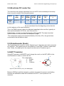
3.1-PID (Proportional + Integral +Differential)
A brief demonstration of the PID controllers’ background which is the most
common controller in industry, the algorithm of this technique is being used in
order to output a better accurate signal regarding to the desired value and to
save energy by giving only what the system needs.
In this closed loop transfer function, the input signal to the PID controller is the
desired (reference) value subtracts by the feedback signal from the output
which called error. The controller receives digital signals and after calculations
the signal forwards to be processed, see figure (2).
Figure 1. Closed Loop
The PID analog calculation is shown as following.
The figure below shows the standard PID controller, it’s the same basic
procedure of using even the digital version, (Embedded programming for the
80x51, Dr. Goran Bezanov).
Figure 2. PID algorithm
Mainly the used PID controller is a digitalized version, thus the equation
consequently digitalized as well.
5
Name: Omar Jones
Course: Electronics Engineering, Final year (3)
3.2-PWM (Puls Width Modulation)
Is a very powerful technique that reduces the cost and time by digitalizing the
analog signals means either on or off, where PWM is monitoring by encoding
the input and decoding the output of the system, to manage analog
device/devices.
The duty cycle represents a ratio between the ON time and the Total time.
In this system a frequency of 500Hz has been provided which makes the Total
time/period 2ms, (Embedded programming for the 80x51, Dr. Goran Bezanov), see
the following figure.
Figure 3. Duty cycle
This could be simplified to the following equations.
The periods that the PID and PWM are running on, have to be ran on the
same period, because the PWM take the duty cycle value from the PID
calculations.
The output from the Arduino is a PWM digital output; thereby it’s connected to
a transistor to control the Fan speed.
Simply it turns the motor on and off to saturate the calculated duty cycle.
The frequency or the named period can be increased or decreased regarding
to the usage and the used device and its won performance; in this project the
regular frequency is used.
Frequency = 1/T; so if T = 2ms, then the frequency is 500Hz.
There are special pins on the Freeduino PCB for the PWM, the new upgrade
of the 8051 family such as; ATmega8 and ATmega168/ATmega328 include
many typical useful features.
A good and simple example of the Puls Width Modulation; if we have a motor
which is connected to a switch, we can switch it On and Off very fast, the
speed of switching on and off is equivalent to the period/frequency in the
PWM.
6
Name: Omar Jones
Course: Electronics Engineering, Final year (3)
So, the time that we spend while the switch is On or Off will set the duty cycle,
apparently if the time is equal on both On and Off will reduce the speed of this
motor to 50%, which is the mentioned duty cycle.
4-Technical approach
The user will be able to manipulate the speed of a DC motor.
Mainly the speed of the DC motor depends on time, for how long this motor will be
On/Off and set the needed power to be delivered to the fan.
The PID controller part is responsible of making accurate algorithms depending on
the input values/errors.
Before forwarding the signal, it must be digitalized and scaled to be implemented in
order to process it to the output. After the delay calculations have been done, the
next step is to generate puls chain to the output.
In the mean time a feedback from the output must be considered to give more
accurate result and to make of it a real closed loop progress.
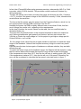
The accuracy itself can be determined regarding to the requirements, in this project
eventually the input signal has been divided into 15 steps/degrees, therefore the
output should be adjusted to give an expected result, see the diagram below.
Figure 4, Flow chart
7
Name: Omar Jones
Course: Electronics Engineering, Final year (3)
4.1.1-Software
Writing the code of any program to be loaded on a microcontroller could be used of
many different IDE (Integrated Development Environment) programs, in this project a
couple of these IDE were tested to produce the suitable code.
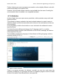
At beginning of writing the first code the Keil uVision2 software was used to code and
dScope to simulate the program, using 8051 microcontroller and C51 compiler.
Keil uVision software is quite popular when it comes to program 8051, a tutorial of
using this program for a relative microcontroller usage was found in (Embedded
programming for the 80x51 book, Dr. Goran Bezanov).
Unfortunately, the tutorial was for a previous released version that was not
compatible with the operative system (Windows7) that installed on my computer, to
solve this problem, Windows XP was installed as a virtual program on Windows7, to
run Keil uVision.
Figure 5, Keil uVision / dScope
The simulator dScope could be run from Keil program from the run (popup menu) as
shown above. The input/output ports operate in 8-bit, the user could see the output
results directly by changing the inputs bits to High or Low.
We can even set the inputs Timer/Counter bits to specify the suitable mode; a
couple of steps should be followed by setting the compiler is C51 and C-language.
After a while AVRstudio 4 was used to code and simulate ATmega8 for the same
program, to see the differences and similarities in using different type of 8051.
Basically the AVRstudio is very similar to Keil uVision, it simulates in the same way
as well, but we can use more types of microcontroller instead, it has a full support to
the Atmel microcontroller, which means that the library of microcontroller is quite
bigger than Keil uVision.
8
Name: Omar Jones
Course: Electronics Engineering, Final year (3)
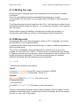
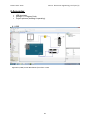
Finally, Arduino open source program was used to code a slightly different code with
same functionality as the earlier code.
However, the last used software was the most suitable due the ease of loading the
microcontroller that is installed on a compatible hardware.
4.1.2-Arduino
Arduino Alpha is the new open source production, which provides many useful and
typical functions.
The software is always updated to the latest related hardware to make it easier to
load the software on the microcontroller and to discover the new features in the new
microcontroller.
A very big library could be found online or even included in the software for some
basic functions.
It’s almost the same differences between the C-language and C++ could be
represented between Arduino and AVRstudio or Keil uVision, although, the Arduino
was programmed by java.
The available programming language in this software is Wiring-language, which is
extremely similar to C/C++.
Figure 6, Arduino software
There’s no regular simulator for Arduino, normally you see the result when the
hardware (Freeduino) is connected, but there’s a separate program used to simulate
Arduino files called Virtual Bread Board, see appendix
9
Name: Omar Jones
Course: Electronics Engineering, Final year (3)
4.1.3-Writing the code
At beginning the C-language was used to produce the functions and the needed
commands.
Since the used software (Arduino) demands Wiring-language to run the
microcontroller, the old version of the program had to be edited to Wiring-language
as well.
The Wiring-language structure is similar to the C/C++, still there are a couple of main
functions names and usage are different; i.e. void main() and while(1), were replaced
with void loop().
Arduino helps to setup the settings of loading and compiling the program, by
choosing the right board port, the type of the hardware and microcontroller.
4.1.4-Wiring-code
As explained above, the Wiring-language is similar to C/C++-language, so we start
with declaration of the needed variables.
A special function called setup is needed though, to make an additional declaration of
the Input/Output ports.
This is only a declaration, it has to be declared in a specific way, to inform the
compiler if it’s an OUTPUT or INPUT, to inform the pin number and the type Analog
or Digital even inside the loop() function, which is equivalent to main() function in the
regular programming languages. The colored selected phrases are standard
reserved commands. See the following function declaration.
void setup()
{
//initialize the variables we're linked to
//Inputs
(1) sensor = analogRead(sensorPin); //read from sensor (LM35D)
(2) setPoint = analogRead(setPointPin); //knob 0-5 V
//Outputs
(3) pinMode(PWM_Pin, OUTPUT); // DC motor control
//Library functions
//turn the PID on
(4) myPID.SetMode(AUTO); // Example on library declaration
}
There are many library files that could be used for different function needs, it’s also
available to download special functions from Arduino homepage, but we are going to
produce our won code in this project.
10
Name: Omar Jones
Course: Electronics Engineering, Final year (3)
We start reading from the potentiometer set the required temperature on the object
that we need to take care of.
The second Input is the feedback value from the sensor, which is a thermometer of
(LM35DH) type.
Again, the first tested temperature sensor was LM335; it works in a very similar way
to the used thermometer LM35DH.
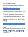
This is a simple comparison between the two tested temperature sensors:
Sensor
Output
Accuracy Basic range
Calibrate
LM335
10mV/Kelvin
±1 °C
-40°C to 100°C
Yes
LM35DH 10mV/°C (Centigrade) ±1⁄4°C
0°C to 100°C
Yes
Table1, Precision Temperature sensors
The first sensor (LM335) was replaced with LM35DH, because it starts within a closer
temperature range to the required one in this project and it gives result in Celsius
Centigrade as well. Now we don’t have to scale the input from the sensor which it
goes in the following way:
Celsius = ( power_supply_voltage * input from sensor * 100 – 273.15 ) / 2^10;
Values that the LM35DH sensor returns are 10mV/°C degree. This means that first
we have to multiply it with 100 to reach 1 °C.
So, if we need to set a specific temperature, we use this:
Celsius = (power_supply_voltage * input from sensor * 100) / 2^10;
Let’s set some temperature degrees!
10°C = (5* input_from_sensor * 100) / 1024;
Input_from_sensor = 20.48 =~ 20 decimal
20°C = 40 decimal
25°C = 51 decimal
10°C is the minimum or the lowest degree that used in the program.
25°C is the maximum or the highest degree in this program.
In these 15 degrees/steps we get 15 different voltages.
To get a linear relationship between the temperature degrees and the input voltage,
starting from this point we have to calibrate the output from the sensor using
hardware, in fact two resistors.
Instead of adding more hardware we can scale the input in program, as we have
already calculated the responding values of the minimum and maximum temperature.
It’s quite essential to convert the current temperature in order to limit the range of the
required temperature and to make code available to be changed to a different range.
To get an accurate temperature, again we can choose either to put three or more
sensors in series, or solve it using code.
11
Name: Omar Jones
Course: Electronics Engineering, Final year (3)
Well, we shall use code as this project emphasize on it, a reading of 10 samples was
implemented, which can be easily changed to the desired samples quantity.
The time delay of reading the ten values is the time that the operations inside the
for() loop takes.
The array contains ten elements adds a new served value each cycle.
When the container is full the next cycle will reset it and start adding new values from
the beginning.
So, first we read ten times and then get the average temperature. This sort of reading
has to be declared inside the setup() function.
void setup()
{
//initialize the variables we're linked to
//read from sensor (LM35DH)
for (int current_Reading = 0; current_Reading < numReadings; current_Reading++)
readings[current_Reading] = 0;
Setpoint = analogRead(1); //knob 0-5 V
pinMode(PWM_Pin, OUTPUT); // DC motor control
}, The Arduino forum (Jones).
Taking several samples would be more elegant solution than just throw a delay, it
would work with the delay too, but it won’t give high accuracy and performance.
void loop()
{
// subtract the last reading:
total= total - readings[index];
// read from the sensor:
readings[index] = analogRead(inputPin);
// add the reading to the total:
total= total + readings[index];
// advance to the next position in the array:
index = index + 1;
// if we're at the end of the array...
if (index >= numReadings)
// ...wrap around to the beginning:
index = 0;
// calculate the average:
average = total / numReadings;
delay(100); // add a 100ms delay
}//[Arduino(2010), functionality ]
As the loop() function is a forever loop, a delay has to be implemented between
calculations and pin reading/writing. The delay function is a standard function in the
Wiring-language, the regular delay(X) whereas X is a value in mille second. There’s
another standard delay function calculates in micro second instead as well.
12
Name: Omar Jones
Course: Electronics Engineering, Final year (3)
In fact, the ATmega328 offers quite generous precision, whereas the A/D-C is 10-bit
converter, which is 1024 decimal. This precision could be reduced if desired, by
Wiring-language.
Though, the sensor has a lower accuracy than what the Arduino can offer. It’s about
+-0.5 °C, but this if the power voltage to the LM35DH is exactly 5 Volts, otherwise this
would effects the resolution.
The fact is that the sensor gets the power from the Freeduino/Arduino, which is in its
turn get the power through USB connection from the PC.
Normally the power via USB is slightly different less or more than 5Volts, this fact
won’t change the results a lot, regarding to the requirements.
In the loop() function the current values can be read, this is a modified code for
illustration sake only.
The input from the potentiometer or the required temperature has to be scaled as
well. As the potentiometer gets power from Arduino, we have two choices the
3.5Volts or 5Volts, the used voltage is 5 in this project to get higher voltage per bit.
5Volts/1023-bit = ca 5 mV/bit
So, the range of the values that the program needs to read have to match the same
range of the feedback. Unless if the required accuracy is high to control very small
values.
Here we have the two choices again of hardware or software solution, they are both
efficient though.
To match the same range as the feedback range, the Setpoint will be scaled in a way
that the values above and beneath this specific range will be treated as following:
If the temperature is less than 10°C, then the fan will stay in waiting mode (Off), and
if the temperature is above 25°C, then the fan will run in full speed. Otherwise, the
error will be considered to calculate the fan speed, note start motor in figure 7.
Figure 7, Input/Output signals
13
Name: Omar Jones
Course: Electronics Engineering, Final year (3)
The difference between the Setpoint and the feedback which called error has to
come to the point to be zero or close to zero at least. PID control function will
calculate these errors to deliver a suitable duty cycle value to the fan as illustrated in
the figure above.
Since the range is between 10°C and 25°C, the corresponding voltage range from
the sensor is between 0.1V and 0.25V respectively.
The conversion to digital will find the way to match the Setpoint and feedback.
5V/(2^n), n = bit
5V/256 ~=20mV/bit
5V/1024 ~= 5mV/bit this is a better accuracy
Obviously we can quantize the minimum voltage change from the sensor at
10mV/°C, it meets the required reading conversion.
0.1V/5mV = 20 decimal resolution; this is the start edge of the mentioned range
0.25V/5mV = 50 decimal resolution; this is the end of the range, maximum.
The other way to calculate it:
(0.1V/5V) * 1024 = 20.48 ~20 decimal resolution
(0.25V/5V) * 1024 = 51.2 ~20 decimal resolution a better calculation
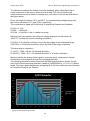
Mainly to define the analog chain signal in ones and zeros, each period of these
chains have to be sampled and get its new digital definition.
The following discrete function shows how the ADC gets the above values, it adds
each level of these bars that operate in range of (0000000000 to 1111111111) binary
levels. The figure below defines the analog signal (0-5)Volts, which the knob will send
to Freeduino to adjust the Setpoint.
A/D Converter
5
5
4.5
4.5
4
4
3.5
3.5
3
3
2.5
2
1.5
2.5
Analog Input
2
Samples
1.5
1
1
0.5
0.5
0
0
0
1
2
3
4
5
6
Figure 8, ADC quantizing function
14
7
8
9
Name: Omar Jones
Course: Electronics Engineering, Final year (3)
Then the interesting range of reading from sensor is 50 – 20 = 30 or 31.
Regarding to the earlier calculation we have 15 steps representing the 15 degrees.
This means that the analog 15 steps equal 30 digital steps, which gives a good rate
margin.
A higher resolution will help to calculate an accurate speed to the fan.
While reading the Setpoint values in the loop() function, the operation of scaling will
take a little time which requires delay, thus the delay() function has to be
implemented after each function.
The minimum limited duty cycle is approximately 12.5% that make the motor runs on
the slowest speed.
The corresponding value in binary (1000 0000), decimal (32), Hex (20); this limitation
merely sets by the DC motor. Apparently the minimum needed voltage is
approximately 0.64V.
Then the error value increases dramatically to adjust the fan speed, by adding this
edge value to the error (sensor – Setpoint).
The default PWM output pin in ATmega328 provides 8-bit, so the full speed takes
255 when the duty cycle is 100% to supply the fan with 5V.
When the internal A/DC gives 10-bit, the ATmega328 provides up to 16-bit to the
PWM output-pin. Output-pins are controlled by Timer/Counter Control Registers, for
each two pins there are two of these Timers/Counters for channel A and Channel B.
Each Timer/Counter contains of 8-bits to control the behavior of the output pins.
By setting the proper timer control, we can get 10-bit to the PWM output-pin as well.
The ATmega328 PWM output-pins are totally 6 pins, in three pairs.
These three pairs are divided in this way, due the fact that we have 3 prescaler.
Let’s have a look first at the PWM pin numbers in ATmega328 and the corresponding
pins in Arduino.
ATmega328 5
Arduino
3
11
5
12
6
15
9
16
10
17
11
Table2, PWM pin number
The reason that the above table mentioned is to explain the code when we are using
the Arduino pins numbers.
Arduino bootloader sets the prescaler and the frequency to the attended pins
automatically at start. Pin 3 and 11 run on 500Hz frequency, when the other pins run
on 1kHz, www.Arduino.cc.
15
Name: Omar Jones
Course: Electronics Engineering, Final year (3)
4.1.4-Timer/Counter Control register
In this case an increment needs to be done to use 10-bit instead of 8-bit.
There are three TCCR (Timer/Counter Control Register), could be modified to the
specific mode and bits in the A channel (TCCRnA).
Timer/Counter Control Register
TCCR0B - TCCR0A
TCCR1B - TCCR1A
TCCR2B - TCCR2A
Pin number (Arduino)
5
6
9
10
3
11
Table3, TCCR
It’s obvious that the change in Timer/counter bit quantity effect the frequency, so if we
want to change it then the prescaler has to be changed.
TCCR = system_clock / prescaler_value.
The frequency could be changed by changing specific bits in the B channel
(TCCRnB) Controller Registers the, bits and Wave Generation Mode to meet the
required behavior to pair/pairs of pins, www.atmel.com.
It’s not possible though to specify different frequency for each pin though, whereas a
Timer/Counter setting applies the concerned two pins.
Nevertheless, there are three pairs that could have three different frequencies.
Basically, there are only two Timers/Counters that have been changed in this project.
Since we need to set pin 5 to write 10-bit for the moment, then pin 5:6, TCCR0A and
TCCR0B have to be modified. An explanation of this modification is illustrated in the
following way:
TCCR0A
Bit
7
6
5
4
TCCR0A
Com1A1 Com1A0 Com1B1 Com1B0
Read/Write
R/W
R/W
R/W
R/W
Initial value
0
0
0
0
3
R
0
2
R
0
1
0
WGM11 WGM10
R/W
R/W
1
1
Table4, TCCR0A
Bit 7:4 are Compare output Mode for Channel A&B; we are only interesting in fast
PWM mode.
Bit 3:2 are reserved.
Bit 1:0 Wave Generation Mode, these bits with combination with WGM13:12 bits (see
table 5, TCCR0B) modifies the type of generation mode.
Mode WGM13 WGM12 WGM11 WGM10
7
0
1
1
1
Table5, Fast PWM mode, 10-bit
16
Timer top
HEX
0x03FF
Top Timer
(Decimal)
1023
Name: Omar Jones
Course: Electronics Engineering, Final year (3)
TCCR0B
Bit
7
TCCR0B
ICNC1
Read/Write R/W
Initial value
0
6
ICES1
R/W
0
5
R
0
4
3
WGM13 WGM12
R/W
R/W
0
1
2
CS12
R/W
0
1
CS11
R/W
1
0
CS10
R/W
1
Table6, TCCR0B
Bit 7 Input Capture Noise Canceller, this bit filters the incoming noise but on the other
hand it will make a longer delay.
Bit 6 Input Capture Edge Select is a trigger capture event.
Bit 5 reserved.
Bit4:3 WGM13:12 Wave Generation Mode.
Bit2:0 Clock Select, these three bits set the prescaler, in other word the frequency
that the mode will run on.
CS12
CS11
CS10
Prescaler
Frequency
0
1
1
64
1kHz
Table7, TCCR0B Frequency
The selected frequency is the default frequency from the bootloader, in case the
wanted frequency is 1kHz, then no need for changing anything in case we need this
particular frequency, www.alldatasheet.com.
The only limitation in this program that caused a faulty on the fan behavior is the fan
switching frequency.
In fact 8-bit output to the PWM pin is more than enough to operate this fan, so the fan
can’t run on a higher frequency than its own frequency.
The solution is to run the fan in 8-bit from pin 3 that operates on 500Hz.
17
Name: Omar Jones
Course: Electronics Engineering, Final year (3)
4.2.1-Hardware Core
In this section we will go through the PCB that ATmega328 installed on and a
comparison between three of 8051 family, those were used in order to achieve this
project.
4.2.2-Freeduino SB 2.2
Freeduino is an upgrade of open source hardware, which is available to everyone to
edit, enhance, share and sell. This kit is uses 16MHz SMD crystal, which is
ATmega328 clock and can deliver up to 500mA, which can be integrated with power
supply to deliver up to 1A.
The hardware compatibility with different operative systems such as; Windows, Linux
and Mac, make of it a very useful and popular product.
In fact, it’s made to be used for motors, LEDs and temperature control projects.
It‘s supplied with PC suitable functionality. The output of programs could be tested on
the LEDs, www.freeduino.org.
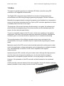
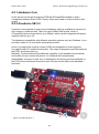
Basically, Freeduino/Arduino provides the capability of the installed microcontroller
and makes it easy to reach the pins of it to interface with external parts.
Nevertheless, the price is quite low; in additional to all the tiny parts are soldered on
the PCB, the picture below shows the used I/O pins and the other main hardware
functions.
Figure 9, Freeduino SB v2.2
18
Name: Omar Jones
Course: Electronics Engineering, Final year (3)
4.2.3-ATmega328 and 8051 Family
Mainly the use of the ATmegaX will give as good result as the 8051. With help of
AVR Studio 4 software we can simulate the C code for ATmega8 which is equivalent
to Keil uVision and Arduino using ATmega328.
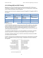
Here’s a very brief technical comparison betweenATmega328, ATmega8 and 8051 in
this project:
Microcontroller
A/D converter
PWM
Timers declaration
Frequent used IDE
Suitable for this
project?
ATmega328
Automatic/editable
10-bit
Special pin
(Automatic)
Automatic/editable
Arduino
Yes
ATmega8
C code (software)
8-bit
Special pin
(Automatic)
Automatic/editable
AVRstudio
Yes
8051
External interface
8-bit
C code (manual)
C code (manual)
Keil uVision
Yes
Table8, 8051 family
The A/D Converter component communicate with the 8051 via P0 Port, which offers
8-pins, furthermore this interface enables a flag informing the 8051 that the packet
has been transferred, Embedded Programming for the 80x51, Dr. Goran Bezanov.
The cost could be reduced by using the ATmega328 instead, whereas the external
A/D Converter will be eliminated.
The PWM (Puls Width Modulation) in the ATmega328 as automatically calculated,
whereas a special Pin as used only to calculate the Duty cycle to the output.
The Arduino software makes it easy to load the code directly to the board via USB
and see the result of the PWM.
However, there are lots of similarities due the fact that all of them belong to the 8051
family, it’s possible to edit any of them using c or assembler the timers, frequency
and registers.
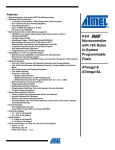
Figure 10, ATmega328, Atmel
19
Name: Omar Jones
Course: Electronics Engineering, Final year (3)
5-Hardware components
The listed hardware components are interfaced with Atmega328 via Freeduino, a
brief description of wiring each component is listed below.
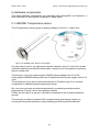
5.1-LM35DH Temperature sensor
The IC temperature sensor gives an analog voltage of 10mV/°C, it has 3 pins:
1
2
3
Figure 11, LM35DH (Left), Bottom View (Right),
It’s quite easy to wire it, the right picture shows a bottom view of it, and so if we start
clockwise starting from the little metal holder, actually it’s for the purpose of pointing
the pin number one.
The first pin (+Vs) is for power supply, LM35DH takes voltage from 4V to 30V.
In this project LM35DH takes power from Freeduino/Arduino power supply, which is 5
volts.
The second pin (Vout) can be connected directly to Freeduino (pin 0) or via other
components to calibrate special temperature range.
We, can even get more accurate temperature by connecting several precision
temperatures in series, this is the hardware solution.
Finally, the third pin is to ground, it should be connected to the Freeduino/Arduino
ground.
The accuracy could be increased if the measurements give strange results, by
covering the legs with aluminum or any shielding method to prevent distortion.
20
Name: Omar Jones
Course: Electronics Engineering, Final year (3)
5.2-Brushless DC motor Fan
The used fan in this project was taken from an old PC at the workshop at University.
Here is a quick review of this fan performance:
Model
D80BH12
Size
Volt
Airflow
Noise
Ampere
(V)
Speed
(RPM)
(CFM)
(dB)
(A)
Manufactur
e
(mm)
80x80x25
12
2700
34.0
35
0.19
Yate Loon
Table9, Fan
A very important aspect that was not considered from the beginning is how fast the
dc fan response to the input frequency.
Thus, the PWM frequency has to be adjusted regarding to the used fan, typically dc
fans operate between 30-150 Hz, www.freescale.com.
Unfortunately, we can’t use the full strength of ATmega328. The tests show that
500Hz is fine to run the fan within the accepted margin.
The used power supply was connected directly to the fan (12V), the ground was
connected to the transistors output.
5.3-Potentiometer (Knob)
10k Ω potentiometer is used to control Setpoint level; it has three pins that connected
to Freeduino. The outside pins are connected to 5V and GND, it doesn’t matter what
side. Finally, the middle pin is the output from the knob to Freeduino (pin 1).
5.4-BJT Transistor
Using BJT transistor or MOSFET won’t change the result, so the BJT (NPN) is the
used transistor in order to control the fan.
3
Pin configuration:
123-
1
Emitter
Base
Collector
2
2
3
1
Figure 12, BJT Transistor (Left), BJT NPN (Right)
Between PWM pin and the transistor a resistor was placed to prevent overheating,
whereas the saturation mode will be different over 25°C, www.rapidonline.com
datasheet.
21
Name: Omar Jones
Course: Electronics Engineering, Final year (3)
5.5-The Project
Let’s put things together, the following figure shows the complete system, the ground
(GND) from Freeduino should be connected to the 12V power supply.
Freeduino
Atmega328
PWM
ADC
12V
+5V
GND
Figure 13, The complete project
There were many tests to define what was missing in wiring and code, though the fan
works fine within an acceptable range in 500Hz from PWM.
At first when the 1kHz frequency on PWM pin was tested, the fan gave a very high
frequency noise but no rotation! When the frequency decreased to 500Hz, the fan
worked fine. Still an enhancement to the result could be done if we replace the used
fan with a better one.
A couple of transistors and thermometers were fried, because of wiring faulty.
There were short in two places, the whole board was replaced with a new one and of
course soldering the components again took a place at the workshop as well.
Checking the small wiring components when unexpected faulty happens is very
essential and will save a lot of time.
The design of how the components are wired could be done in a better way.
Although, the knob for the potentiometer was in the way, under trying to put
everything in a box to give the hardware a descent looks.
22
Name: Omar Jones
Course: Electronics Engineering, Final year (3)
6-Result
The project as final step used Arduino as IDE, ATmega328 microcontroller placed on
Freeduino with output on pin 3 for PWM which runs on 500Hz.
Basically, the results of each method were explained with relevant details after the
concerned steps.
Mainly the project worked as planned, the fan runs regarding to the Setpoint and the
sensor feedback. The Fan runs very smooth between the different speed levels
regarding to the PID implemented values, see appendixes.
The idea of making this project was a suggestion from Dr.Goran Bezanov the
supervisor of this project at London South Bank University.
The purpose of this suggestion is to reduce costs and time by using embedded
solutions with simple electronics circuits.
6.1-List of used Hardware/Software
Software
o IDE (Integrated Development Environment)
Kiel uVision/dScope, 51 evaluation
AVRstudio 4
Arduino
Virtual Bread Board simulator
o Documentation
Microsoft Word
Microsoft Excel
Smart Draw
Paint
Hardware
Atmega328
Freeduino/Arduino (Atmega328, ADC)
Resistor (1 x 4.7 k Ω)
Transistor (1 x NPN BJT)
Thermometer/knob (1 X LM35DH)
Potentiometer (1 x 10k Ω)
Fan (1 x DC motor, 12V, 0.19A)
PC, box, wires & soldering.
23
Name: Omar Jones
Course: Electronics Engineering, Final year (3)
6-Project Planning
A Gantt chart was build to match the requirements and the deadlines.
Figure 14, Gant Chart
The plan and some other additional parts were changed due the fact that a better
solution was found, though the core of the old plan was held very close to the
approached plan.
Basically, almost all the milestones were fulfilled successfully, except that the final report
was expected to be submitted four days earlier.
A special edition of this report was edited specifically to follow the Linköping University
requirements, thus it took a little further time to be submitted.
24
Name: Omar Jones
Course: Electronics Engineering, Final year (3)
7-References
[1] G. Bezanov, Embedded programming for the 80x51, Published by MIG Consulting
Ltd, London, 2008. ISBN: 9780955815317
[2] Power Electronics, Converters, Applications and design
[3] Mohan, Undeland and Robbins, Power Electronics, Converters, Applications and
design, published by Wiley ISBN 0-471-50537-4.
[4] Atmel, datasheet.(2010)
www.atmel.com/dyn/resources/prod_documents/doc8271.pdf (2010-05-09).
[5] IDE new software (2010)
www.arduino.cc (2010-05-09).
[6] Microcontroller circuit packet (2010)
www.freeduino.org (2010-05-09).
[7] BJT & Sensors (2010)
www.alldatasheet.com (2010-05-09).
[8] The Wiring-Language functionality (2010)
www.tem.eu (2010-05-09).
[9] Arduino IDE (2010)
www.virtualbreadboard.com (2010-05-09).
[10] Freeduino Circuit (2010)
www.solarbotics.com / (photo) (2010-05-09).
25
Name: Omar Jones
Course: Electronics Engineering, Final year (3)
8-Appendex
VBB simulator.
Wiring/C++ Program Code.
Project pictures (building & operating).
8.1-VBB
Appendex1, VBB (Virtual Bread Board) simulator v3.6.0
26
Name: Omar Jones
Course: Electronics Engineering, Final year (3)
8.2-Code
/***********************************************************************************************
Final Year Project
Title: DESIGN AND DEVELOPMENT OF AN EMBEDDED DC MOTOR CONTROLLER
USING A PID ALGORITHM
Author: Omar Jones.
Course: Bachelors Electronics/Electrical Engineering.
Submission date: 27th of May 2010.
Introduction: PID control, DC motor control (Fan) via PWM pin, on ATmega328 With
setpoint & sensor.
Software: Arduino, Wiring-language
Hardware: Freeduino
**************************************************************************************************/
//Define Variables we'll be connecting to
double Setpoint, Input, tmp = 0;
const int numReadings = 10;
int readings[numReadings];
// the readings from the analog input
int index = 0;
// the index of the current reading
int total = 0;
// the running total
int average = 0;
// the average
int Duty_C = 0;
int error = 0;
int prev_error = 0;
int out = 0;
double P_Gain = 2, I_Gain = 0.3, D_Gain = 0.3; // PID Coefficients example
//I/O pin numbers
int sensorPin = 0;
int setpointPin = 1;
int PWM_Pin = 3;
void setup()
{
//initialize the variables we're linked to
//read from sensor (LM35DH)
for (int thisReading = 0; thisReading < numReadings; thisReading++)
readings[thisReading] = 0;
Setpoint = analogRead(1); //potentiometer 0-5 V
pinMode(PWM_Pin, OUTPUT); // DC motor control
}
//------------------------------------ Function prototype---------------------------int pid(int error_ctrl, int prev_error_ctrl);
//----------------------------------- "Main" function ----------------------------------
27
Name: Omar Jones
Course: Electronics Engineering, Final year (3)
void loop()
{
Setpoint = analogRead(setpointPin); //reading setpoint
delay(100); //100ms delay
//Reading temperature average of 10 samples
// subtract the last reading:
total= total - readings[index];
// read from the sensor:
readings[index] = analogRead(sensorPin);
// add the reading to the total:
total= total + readings[index];
// advance to the next position in the array:
index = index + 1;
delay(50);//50ms delay
// if we're at the end of the array...
if (index >= numReadings)
// ...wrap around to the beginning:
index = 0;
// calculate the average:
average = total / numReadings;
// send it to the computer (as ASCII digits)
delay(20); //20ms delay
//Temperature = (5*average*100)/1024
if(average <= 20 )// if the temperature is too low (equal to or less than 10 degrees)
{
digitalWrite(13,HIGH); //turn the blue LED on, which is connected to the digital pin 13
out = 0;
analogWrite(PWM_Pin, out); // Fan off
delay(100);
}
/*
else if (average > 52) /
{
analogWrite(PWM_Pin, 255); //Fan Full speed , it's too hot!
delay(100);
}*/
else //otherwise calculate the needed speed
{
tmp = analogRead(1); //reading setpoint
Setpoint = tmp/10;
delay(100);//100ms delay
28
Name: Omar Jones
Course: Electronics Engineering, Final year (3)
error = average - Setpoint; //calculate the difference
delay(10);//10ms delay
if(error > 1)
{
Duty_C = pid(error, prev_error); // call pid function
out = error ;//+ 32; //run fan , calculated error + minimum output to run the fan
delay(200); //200ms delay
analogWrite(PWM_Pin, out); // write to the Fan
digitalWrite(13,HIGH); // write to the blue cool diod
delay(500); //0.5s delay
prev_error = error; //save old error to be used by the PID function
Duty_C = 0; // reset register
}
else
{
out = 0;
analogWrite(PWM_Pin, out); // motor off it's too cold and start blinking the blue diod
digitalWrite(13,HIGH); // write to the blue cool diod
delay(200);
digitalWrite(13,LOW); // write to the blue cool diod
delay(200);
}
}
}
//End Main
//------------------------------------PID Function ---------------------int pid(int error_ctrl, int prev_error_ctrl)
{
double p = 0, i = 0, d = 0;
int sum = 0;
p = P_Gain * error;//Proportional part
i= I_Gain * (error_ctrl + prev_error_ctrl); //integral part
d = D_Gain * (error_ctrl - prev_error_ctrl); //derivative part
sum = p + i +d; // PID
return sum;
} //Program End
29
Name: Omar Jones
Course: Electronics Engineering, Final year (3)
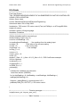
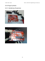
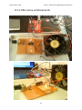
8.3-Project photos
8.3.1-Soldering Freeduino
30
Name: Omar Jones
Course: Electronics Engineering, Final year (3)
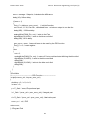
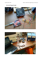
8.3.2-Project test
31
Name: Omar Jones
Course: Electronics Engineering, Final year (3)
8.3.3-After some enhancements
32
Name: Omar Jones
Course: Electronics Engineering, Final year (3)
Upphovsrätt
Detta dokument hålls tillgängligt på Internet – eller dess framtida ersättare – under 25 år från
publiceringsdatum under förutsättning att inga extraordinära omständigheter uppstår.
Tillgång till dokumentet innebär tillstånd för var och en att läsa, ladda ner, skriva ut
enstaka kopior för enskilt bruk och att använda det oförändrat för ickekommersiell forskning
och för undervisning. Överföring av upphovsrätten vid en senare tidpunkt kan inte upphäva
detta tillstånd. All annan användning av dokumentet kräver upphovsmannens medgivande.
För att garantera äktheten, säkerheten och tillgängligheten finns lösningar av teknisk och
administrativ art.
Upphovsmannens ideella rätt innefattar rätt att bli nämnd som upphovsman i den
omfattning som god sed kräver vid användning av dokumentet på ovan beskrivna sätt samt
skydd mot att dokumentet ändras eller presenteras i sådan form eller i sådant sammanhang
som är kränkande för upphovsmannens litterära eller konstnärliga anseende eller egenart.
För ytterligare information om Linköping University Electronic Press se förlagets hemsida
http://www.ep.liu.se/.
Copyright
The publishers will keep this document online on the Internet – or its possible replacement –
for a period of 25 years starting from the date of publication barring exceptional
circumstances.
The online availability of the document implies permanent permission for anyone to read,
to download, or to print out single copies for his/hers own use and to use it unchanged for
non-commercial research and educational purpose. Subsequent transfers of copyright cannot
revoke this permission. All other uses of the document are conditional upon the consent of the
copyright owner. The publisher has taken technical and administrative measures to assure
authenticity, security and accessibility.
According to intellectual property law the author has the right to be mentioned when
his/her work is accessed as described above and to be protected against infringement.
For additional information about the Linköping University Electronic Press and its
procedures for publication and for assurance of document integrity, please refer to its www
home page: http://www.ep.liu.se/.
© Omar Jones
33