1
HEC-102x Features
Digital Outputs
The HEC-102x includes 6 on-board digital outputs. They are identified in the EZ LADDER Toolkit and this manual as GPO0 - GPO5.
These outputs are sourcing, therefore an energized output will source an output voltage equal to the controller input voltage. Refer
to Figure 2.7 for typical output connections.
Each output can drive a load up to maximum current rating listed in the specifications section (resistive) and includes an automatic
over-current shutdown safety. In the event an over current condition exists, the output will shut down. This shut down condition is
reset when the output is turned off (set to false) in the ladder diagram.
Each output requires a minimum load to operate correctly. Depending upon the device connected to an output, a minimum load
resistor may be required. If the output is ON or true regardless of the ladder diagram program, connect a 470Ω to 1KΩ load from
the output to input power common.
Each digital may be configured and used as a digital output or as a Pulse Width Modulation (PWM). Each output may only be used
as either digital output or PWM output only. For information on using digital outputs as PWM outputs, refer to the Pulse Width
Modulation Outputs Section of this manual.
To control a digital output in a ladder diagram, place and connect the appropriate coil for your needs. The DIRECT COIL and INVERTED COIL functions are used to control digital outputs in the ladder diagram. When placing the coil, verify you select the correct
output address (GPO0 - GPO5) from the provided drop-down menu.
In addition to controlling the outputs, the status of each digital output may be monitored for an OK or Fault status. When the HEC102x target is configured in EZ LADDER, 6 status variables are created automatically, idenfitied (STAT0 - STAT6). These variables indicate the status of the output and may be used in the program as any boolean variable (DIRECT CONTACT or INVERTED CONTACT). A
High or True condition indicates that the output is functioning properly while a Low or False condition indicates a fault condition of
the output (open load or overload).
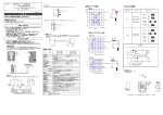
Figure 2.7 - Typical Digital Output Connections
HEC-102X User’s Manual
Document #: 2009004.0.pdf
Divelbiss Corporation • 9778 Mt. Gilead Road • Fredericktown, Ohio 43019 • 1-800-245-2327 • www.divelbiss.com
PAGE 13 of 20