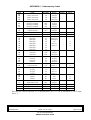
1
Installation, Operating
and Maintenance
Manual
Remote explosimeter/
catharometer
DMTX63/DMTK63
Issue 1 of 31.10.03
+NOSP0014456
Explosimeter / Catharometer
You have just acquired an SIMRAD OPTRONICS ICARE remote
explosimeter or catharometer and we thank you.
Thorough studies have been undertaken on this product to
guarantee you maximum operating safety, large flexibility of
use and maintenance whilst proposing excellent performance.
This manual is meant for the installer, the operator and the
maintenance department.
After the general and technical specification chapters, every
building trade will find the chapters corresponding to its
necessary information.
Reading the present manual is essential for any person intervening at
installation level and before the first installation, at operating level and
at equipment maintenance level.
INSTALLATION, OPERATING AND MAINTENANCE MANUAL DMTX63/DMTK63
page : 2 / 62
Issue 1 of 31.10.03
ALL RIGHTS RESERVED
SIMRAD OPTRONICS ICARE
+NOSP0014456
CONTENTS
1
GENERAL REMARKS..................................................................................................6
1.1 PRESENTATION ...........................................................................................................6
1.2 MULTICHANNEL MONITORING UNIT AND INDUSTRIAL PROGRAMMABLE CONTROLLERS .......7
1.3 SYNTEL GAS AND FLAME DETECTION SECURED NETWORK.............................................8
1.4 EASY INSTALLATION ....................................................................................................8
1.5 REMOVABLE CARTRIDGE .............................................................................................9
1.6 REMOTE CONTROL ......................................................................................................9
1.7 IDENTIFICATION AND MARKING ................................................................................... 10
1.8 ARCHITECTURE ......................................................................................................... 12
1.9 BREAKDOWN............................................................................................................. 13
2
TECHNICAL SPECIFICATIONS .................................................................................... 14
REFERENCE STANDARDS FOR EXPLOSIVE ATMOSPHERES
2.1 CERTIFICATION AND
AND EMC ............................................................................................................... 14
2.2 STORAGE ................................................................................................................ 15
2.3 POWER SUPPLY ....................................................................................................... 15
2.4 PERFORMANCE ...................................................................................................... 16
3
INSTALLATION............................................................................................................. 17
3.1 FITTING THE SUPPORT ............................................................................................. 17
3.2 ELECTRICAL CONNECTIONS.................................................................................. 17
3.3 INSTALLING THE HOUSING..................................................................................... 24
3.4 ACCESSORIES......................................................................................................... 25
4
STARTUP ...................................................................................................................... 26
4.1 CHECK GAS TYPE MARKING ................................................................................. 26
4.2 CHECK THE WIRING ............................................................................................... 26
4.3 CHECK THE MECHANICAL ASSEMBLY .................................................................. 27
4.4 POWER-UP .............................................................................................................. 27
4.5 CHECK SYSTEM FUNCTIONS .................................................................................. 27
INSTALLATION, OPERATING AND MAINTENANCE MANUAL DMTX63/DMTK63
+NOSP0014456
Issue 1 of 31.10.03
ALL RIGHTS RESERVED
SIMRAD OPTRONICS ICARE
page: 3 / 62
5
OPERATION ................................................................................................................ 28
5.1 0-22 MA PROTOCOL .................................................................................................. 28
5.2 4-20 MA PROTOCOL.................................................................................................. 30
5.3 AMBIGUITY FUNCTION IN DMTX63 EXPLOSIMETER REMOTE SENSORS ........................... 32
5.4 RELAY OUTPUTS ........................................................................................................ 33
6
ADJUSTMENT OF EXPLOSIMETER/CATHAROMETER REMOTE SENSORS.................... 34
6.1 MAIN SCREEN......................................................................................................... 34
6.2 MENU STRUCTURE............................................................................................... 36
6.3 MAIN MENU............................................................................................................ 39
7
MAINTENANCE........................................................................................................... 48
7.1 REMOTE SENSOR REMOVAL AND REASSEMBLY ................................................... 48
7.2 REPLACING THE CARTRIDGE ................................................................................. 49
7.3 PREVENTATIVE MAINTENANCE.............................................................................. 49
7.4 CORRECTIVE MAINTENANCE ................................................................................ 50
8
SPARE PARTS............................................................................................................... 52
9
WARNINGS ................................................................................................................. 53
9.1 FOREWORD............................................................................................................. 53
9.2 OWNERSHIP AND CONFIDENTIALITY..................................................................... 53
9.3 LIABILITY.................................................................................................................. 53
10 WARRANTY COVERAGE ............................................................................................ 53
INSTALLATION, OPERATING AND MAINTENANCE MANUAL DMTX63/DMTK63
page : 4 / 62
Issue 1 of 31.10.03
ALL RIGHTS RESERVED
SIMRAD OPTRONICS ICARE
+NOSP0014456
LIST OF FIGURES
Figure 1 : Layout Drawing ............................................................................................... 13
Figure 2 : Detailed View of Cable Gland and Cable Assembly................................. 19
Figure 3 : Location of Grounding Terminal on Support................................................ 20
Figure 4 : Connection diagram to control unit or IPC ................................................. 22
Figure 5 : Connection diagram for relays 1 and 2 ....................................................... 23
Figure 6 : Setting the Housing to the Correct Angle .................................................... 24
Figure 7 : Installed Components to be Checked ......................................................... 26
Figure 8 : 0-22 mA Protocol............................................................................................. 29
Figure 9 : 4-20 mA Protocol............................................................................................. 31
Figure 10 : Curve to show the limits of explosiveness ................................................... 32
LIST OF SCREENS
Screen 1: Example of a Main Screen ............................................................................ 35
APPENDICES
APPENDIX 1 : Gas and Vapor Explosimetry Codes .......................................................... 55
APPENDIX 2 : Catharometry Codes.................................................................................. 59
APPENDIX 3 : Drill Hole Template for Support Attachment............................................... 60
APPENDIX 4 : EC conformity declaration for Dm .............................................................. 61
APPENDIX 5 : EC conformity declaration for the TCM02 part........................................... 62
INSTALLATION, OPERATING AND MAINTENANCE MANUAL DMTX63/DMTK63
+NOSP0014456
Issue 1 of 31.10.03
ALL RIGHTS RESERVED
SIMRAD OPTRONICS ICARE
page: 5 / 62
1
1.1
GENERAL REMARKS
PRESENTATION
The DMTX63/DMTK63 remote explosimeter/
catharometer is designed to monitor the
risks of explosion induced by the presence
of inflammable gases or vapors (hydrogen,
hydrocarbons, alcohol, etc.).
The DMTX63 remote explosimeter is a
thermocatalytic sensor whereas the DMTK63
catharometer measures gas by thermal
conductivity.
The sensor is calibrated on the LEL (Lower
Explosive Limit) scale for a particular vapor
or gas (hydrogen, hydrocarbons, amines,…)
The measurement principle for the DMTX63 explosimeter requires a minimum
oxygen content to function correctly. In the event of a prolonged lack of
oxygen, the signal will no longer be representative of the actual concentration.
It’s characteristics may also be altered by certain poisons (silicones, etc.).
Use of the DMTX63/DMTK63 is simple and versatile thanks to the TLU 600/610
remote control (software versions 3 and up) which allows a large number of
settings and the display of information. With this remote control, maintenance
operations in classified zones can be undertaken by one person.
The TLU600/610 remote control can be used with the entire range of remote
sensors and network remote sensors.
INSTALLATION, OPERATING AND MAINTENANCE MANUAL DMTX63/DMTK63
page : 6 / 62
Issue 1 of 31.10.03
ALL RIGHTS RESERVED
SIMRAD OPTRONICS ICARE
+NOSP0014456
1.2
MULTICHANNEL MONITORING UNIT AND INDUSTRIAL PROGRAMMABLE CONTROLLERS
The DMTX63/DMTK63 can be connected, either to a 4-20 mA channel board of
an SIMRAD OPTRONICS ICARE multichannel gas detection unit, or directly to a
4-20 mA or 0-22 mA input of a commercially-available PLC.
The DMTX63/DMTK63 also has two integrated and programmable relay outputs
which enable it to be connected to a control unit or to directly activate
automatic controls.
INSTALLATION, OPERATING AND MAINTENANCE MANUAL DMTX63/DMTK63
+NOSP0014456
Issue 1 of 31.10.03
ALL RIGHTS RESERVED
SIMRAD OPTRONICS ICARE
page: 7 / 62
1.3
SYNTEL GAS AND FLAME DETECTION SECURED NETWORK
The DMTX63/DMTK63 explosimeter can also be connected to the SYNTEL
secured network thanks to the DMRX63/DMRK63 version, as can the whole
range of SIMRAD OPTRONICS ICARE detection products.
For any further information regarding this topology, please contact us.
1.4
EASY INSTALLATION
The housing used consists of two parts: A wall-mounted support with the cable
gland and a housing unit where the electronics and the detection cartridge
are located.
It is possible to assemble and dismantle the electronics unit or the cartridge
without removing the cable from the cable gland, which reduces the time
required for installation and maintenance and lowers the risks of damaging the
cable and the metal armoring.
INSTALLATION, OPERATING AND MAINTENANCE MANUAL DMTX63/DMTK63
page : 8 / 62
Issue 1 of 31.10.03
ALL RIGHTS RESERVED
SIMRAD OPTRONICS ICARE
+NOSP0014456
1.5
REMOVABLE CARTRIDGE
The detection cartridges are removable following a safety procedure.
They are common to the entire range of SIMRAD OPTRONICS ICARE
explosimeters/catharometers
(DMRX60,
DMRX61,
DMRX63,
DMRK60,
DMRK61and DMRK63 network remote sensors, DMTX60, DMTX61, DMTX63,
DMTK60, DMTK61 and DMTK63 remote sensors and DMCX60, DMCX61, DMCK60
and DMCK61 compact sensors) in order to reduce the number of spare parts
required.
1.6
REMOTE CONTROL
Use of the TLU 600/610 remote control means that maintenance and
calibration operations in classified zones can be carried out by one person.
User-friendly menus associated to the function keys allow zero point setting,
calibration, calibration gas parameter setting, and display of the measurement
reading in % LEL, the name of the measured gas and the remote sensor’s status
(inhibited, fault, ...)
The TLU 600/610 remote control operates with the entire range of remote
sensors and network remote sensors.
INSTALLATION, OPERATING AND MAINTENANCE MANUAL DMTX63/DMTK63
+NOSP0014456
Issue 1 of 31.10.03
ALL RIGHTS RESERVED
SIMRAD OPTRONICS ICARE
page: 9 / 62
1.7
IDENTIFICATION AND MARKING
The SIMRAD OPTRONICS ICARE range of gas detectors can be broken down
into several families of detectors ensuring different types of protection for
different gases. The original reference system below is used to identify the main
characteristics of an SIMRAD OPTRONICS ICARE detector.
Explanation of the References
COMPLETE DESIGNATION
Generic designation
C
T
Cartridge reference
60
A
M
01
-A
Type of housing
Type of output
Type of cell
Characteristics
Type of
material
-A:
Aluminium
housing
and
cartridge
- X : SS
housing
and
cartridge
Detector
Family
C : compact
Type of
detection
T : Toxicity
60 : BT 606
M : 1 - 2 mA
TOX/02 :
T : Remote
sensor
O : Oxygen
61 : BT606 high
A : 0 - 22 mA
M : SIMRAD
OPTRONICS ICARE
See appendix C
R : Network
X : Explosimeter
62 : BT606 low temperature
E : 4 - 20 mA
Y : Toxicity
and D dated
D9606012
E : Echo
K:
Catharometer
I : IR polling
05 : BT05 (alu)
L : LON
N : Toxicity
07 :BT07 (SS)
W:
Wheatstone
G : Toxicity
V : ultraviolet
and infrared
50 : UVIR rect.
OTHERS :
40 : IREX rect.
63 : BT606 + digital board
64 : BT606 + digital board +
low temp.
08 : PVC box for echo
X : Explosimeter
K : Catharometer
I : IREX
atmosphere
R : IREX
circulation
V : UV + IR2
W : UV
D : IR + IR
S : Surface
conversion type
C : input courant
The various characteristics which identify the detector for the different users are
specified on a label placed on the underside of the detector’s main body and are :
- manufacturer :
SIMRAD OPTRONICS ICARE
- model :
DM…
- serial n°:
S/N : xxxxxxxxx
II2G / EEx d IIC T6
- approval type:
CE 0081
- certification number :
LCIE 03 ATEX 6263
- following warnings:
Do not open while energized
- degree of protection:
IP66
INSTALLATION, OPERATING AND MAINTENANCE MANUAL DMTX63/DMTK63
page : 10 / 62
Issue 1 of 31.10.03
ALL RIGHTS RESERVED
SIMRAD OPTRONICS ICARE
+NOSP0014456
- voltage :
- consumption :
VDC : 28V
W:
As shown in the reference table, there are several types of cell corresponding
to the different SIMRAD OPTRONICS ICARE gas detectors. In order to facilitate
their identification, a color-code system is used on the cell identification ring –
yellow corresponds to thermocatalytic cell type explosimeters and brown
corresponds to catharometers.
This label also indicates the type of gas and the range for which it is intended.
Of course, to ensure correct operation of the assembly, these indications must
be the same as those marked on the label fitted on the detector itself.
INSTALLATION, OPERATING AND MAINTENANCE MANUAL DMTX63/DMTK63
+NOSP0014456
Issue 1 of 31.10.03
ALL RIGHTS RESERVED
SIMRAD OPTRONICS ICARE
page: 11 / 62
1.8
ARCHITECTURE
The DMTX63/DMTK63 explosimeter/catharometer can be connected to a
multichannel detection unit like the SIMRAD OPTRONICS ICARE MDXi. The
SIMRAD OPTRONICS ICARE MDXi uses the 4-20 mA output produced by the
sensor to provide status information or to activate control functions.
Each detector and the supervision unit are connected by means of 3 or 4 wire
armored cables for the power supply and for the 4-20 mA signal.
For connection to the multichannel detection unit, a 3-wire cable is used (2 for
the power supply and 1 for the signal). For PLCs, the connection can be via
3-wire or 4-wire cables (2 for the power supply and 2 for the signal) thus
allowing the isolation of the signal from the power supply.
For more information on connections, see 3.2
MDXi Unit or PLC
icare
MDXic
0
4 P
V
5 6 7 8 9 T
1 2 3
I A
Safe zone
Classified zone
INSTALLATION, OPERATING AND MAINTENANCE MANUAL DMTX63/DMTK63
page : 12 / 62
Issue 1 of 31.10.03
ALL RIGHTS RESERVED
SIMRAD OPTRONICS ICARE
+NOSP0014456
1.9
BREAKDOWN
The remote explosimeter/catharometer sensors comprise:
- A wall-mounted support secured by two screws, with a cable gland
and three plugs, which can be replaced by cable glands if necessary
(see chapter 3.3 "Accessories").
- An explosion-proof housing containing a printed circuit board and an
intrinsic-safety protection board and equipped with an external IR
communication head which can be swiveled vertically. In addition,
since the fitting for the support cover is circular, this housing can be
secured in one of three angular positions, thus allowing the IR
communication head to be placed to the left, opposite or to the right
of the support (see Figure 6 : Setting the Housing to the Correct Angle,
page 24).
- A colored cartridge (yellow for the explosimeters and brown for the
catharometers) located in the lower part of the detector is connected
to the sensor by a hollowed bolt which leaves the label visible.
Support cover
Plug
Housing/support
screw
IR head retaining
screw
Braiding
clamp
Cable gland
O-ring
Screw
holes
Grounding
bolt and
lug
167
Locating
pin
Label
IR communication
head
Cartridge
O-rings
Housing
Bolt stop
screw
Label
Bolt
-
184
Figure 1 : Layout Drawing
INSTALLATION, OPERATING AND MAINTENANCE MANUAL DMTX63/DMTK63
+NOSP0014456
Issue 1 of 31.10.03
ALL RIGHTS RESERVED
SIMRAD OPTRONICS ICARE
page: 13 / 62
2
TECHNICAL SPECIFICATIONS
2.1
CERTIFICATION AND
AND EMC
REFERENCE STANDARDS FOR EXPLOSIVE ATMOSPHERES
The equipment has been designed to meet the most stringent European and
product standards, as listed below:
-
European Directive 94/9/CE for products intended for operation in
explosive atmospheres (commonly called the ATEX directive). For the
certified equipment, this is shown on the detector's label by the symbol
, along with the required protection rating and the number of the
approval obtained from a certified laboratory. The directive refers to the
harmonized European Standards satisfied by the detector as listed below:
• EN 50014 (1997) + amendments 1 and 2,
• EN 50018 (2000) + amendment 1,
• EN 50054 (1992),
• EN 50057 (1992).
-
European
Directive
89-336/CEE
concerning
Electromagnetic
Compatibility applicable to SIMRAD OPTRONICS ICARE detectors. The
directive refers to the harmonized European Standards satisfied by the
detectors with regards to the environment
Industrial environments :
• EN 50 081-2: 1993
• EN 50 082-2: 1995
Residential, commercial and light industrial environments :
• EN 50 081-1: 1992
• EN 50 082-1: 1992
Protection rating ensured by the detector housing: IP66 in accordance with
standard EN 60529: 1991.
INSTALLATION, OPERATING AND MAINTENANCE MANUAL DMTX63/DMTK63
page : 14 / 62
Issue 1 of 31.10.03
ALL RIGHTS RESERVED
SIMRAD OPTRONICS ICARE
+NOSP0014456
OPERATING ENVIRONMENT CONDITIONS
• Temperature:
Between -20°C and +60°C,
• Pressure:
1013 hPa ± 10%,
• Relative humidity:
0 - 95% RH without condensation,
• Dust:
To ensure optimum operation, do not
place the compact sensor in a dusty
atmosphere.
Certain situations may be critical to the operation and maintenance of
these instruments. In chapter 3.4, SIMRAD OPTRONICS ICARE proposes a
series of accessories that will meet your needs. For further technical details
concerning the explosimeter compact sensors and their cartridges, see
the performance table in chapter 2.5.
2.2
STORAGE
Detectors and cartridges must be stored in their original packaging. To
guarantee their metrological characteristics, it is essential to store the
cartridges in their original packaging until installation, in compliance with
the conditions described in the accompanying manuals.
2.3
• Temperature:
between -30°C and +70°C,
• Pressure:
1013 hPa ± 10%,
• Relative humidity:
0 - 95% RH without condensation,
• Shelf life:
If a cartridge is to be stored for more
than one year, it must be subjected
to metrological testing by ICARE OTUS
SUPERVISION in order to ensure
operation of the detector on which it is
fitted.
POWER SUPPLY
• Rated voltage:
24 VDC,
• Power supply range :
The power supply voltage must be
between 18 VDC and 30 VDC
• Power consumption:
2W maximum
• Power transients:
Can withstand power transients less
than or equal to 100 ms,
The electrical installation must conform to the applicable rules and
regulations. Particular attention must be paid to safety and
electromagnetic compatibility. Please refer to the applicable standards
and regulations.
INSTALLATION, OPERATING AND MAINTENANCE MANUAL DMTX63/DMTK63
+NOSP0014456
Issue 1 of 31.10.03
ALL RIGHTS RESERVED
SIMRAD OPTRONICS ICARE
page: 15 / 62
2.4
PERFORMANCE
CATHAROMETERS
PERFORMANCES
EXPLO
H2
CO2
HE
Ranges
100 %
L.E.L.
5% vol
20% vol
100% vol
20% vol
5% vol
20% vol
100% vol
τ (0-90%) (sec)
< 15 n
< 10
< 30
< 10
Zero point stability o
<3
<3
<3
<3
Sensitivity drift o
<3
<3
<3
<3
T° range (°C)
-20 / +60
Zero drift o p
<1
<3
<5
<3
Temperature sensitivity drift in T°o p
<3
<3
<5
<3
Linearity o
<3
<2
<2
<2
Precision o p
<6
<6
<9
<6
Repeatability o
<1
<1
<1
<1
Service life (years)
3
10
10
10
Relative humidity (% RH)
0 - 95
15 - 95
15 - 95
15 - 95
Pressure range
Pa±10%
-20 / +60 -20 / +60 -20 / +60
Pa ± 10 % Pa ± 10 % Pa ± 10 %
All
All gases with either very high or
inflammable very low thermal conductivity
compounds
Cross sensitivity
Poisons
Silicon
compounds
and certain
halogen
compounds
None
None
None
Effect of O2 –enriched or depleted atmospheres
10 % O2
min.
None
None
None
Warm-up or biasing time
< 1 min
< 1 hour
< 1 hour
< 1 hour
n Methane reaction time
o In % of scale
p In the range: -10°C to +40°C.
INSTALLATION, OPERATING AND MAINTENANCE MANUAL DMTX63/DMTK63
page : 16 / 62
Issue 1 of 31.10.03
ALL RIGHTS RESERVED
SIMRAD OPTRONICS ICARE
+NOSP0014456
3
INSTALLATION
The detectors described in this manual are safety instruments intended to be
installed in explosive atmospheres and have been designed in compliance
with standards EN50014: 1997 and EN50058: 2000. We wish to emphasize the
importance of taking particular care when installing this equipment on site.
Failure to comply with the instructions herein could result in malfunctions in
SIMRAD OPTRONICS ICARE equipment, which may no longer ensure the
degree of safety for which it was designed.
Reminder to the user : When working on certain sites, restrictions may apply
which you are advised to respect for your own sake and for the safety of
others.
3.1
FITTING THE SUPPORT
Before fixing the remote sensor support cover, it is first necessary to determine
which type of gas is to be detected since the height at which the remote
sensor is to be mounted will depend on the density of the gas.
For example, a remote sensor intended to detect hydrogen (density = 0.07) will
be positioned high up (e.g. on the ceiling) whereas for a heavy gas like butane
(density = 2.11), it will be positioned low down.
To determine the position at which the remote sensor should be fitted see the
tables in appendices 1 and 2 for the density of the different gases.
In addition, the remote sensor must be positioned as near as possible to
potential leak sources and air flow must be taken into account.
(e.g. upper and lower ventilation)
You will find a drilling template in APPENDIX 3 page 60, to help respect the
center distance between the support cover drill hole axes. Use two 6 mm
diameter screws to secure the support.
3.2
ELECTRICAL CONNECTIONS
3.2.1 INSTALLATION RECOMMENDATIONS
∗ Always switch off the power supply before making connections.
∗ Respect the connection specifications relative to each instrument in the
installation.
∗ Use the recommended cables.
∗ When inserting the cables into the support, respect the installation
instructions.
∗ Use suitable cable end fittings.
∗ Respect the specifications when connecting cable shielding.
INSTALLATION, OPERATING AND MAINTENANCE MANUAL DMTX63/DMTK63
+NOSP0014456
Issue 1 of 31.10.03
ALL RIGHTS RESERVED
SIMRAD OPTRONICS ICARE
page: 17 / 62
3.2.2 CABLE CHARACTERISTICS
The cable type must be chosen in accordance with applicable regulations.
In France, for zones classified as explosion risk zones, we recommend the use of
NF M 87 202 armored, shielded cables in compliance with the requirements of
standard NF C 15 100.
The table below defines the maximum acceptable lengths under a minimum
power supply voltage of 20 VDC at the line input, for the most frequently used
cable sections.
Copper conductor section
in mm
Maximum permitted
cable length
in m
0.5
0.9 / 1
1.5
Std. heating pwr = 1W
500
1000
1500
Heating pwr ≥ 2W
300
600
1000
Table 1: Cable Lengths
INSTALLATION, OPERATING AND MAINTENANCE MANUAL DMTX63/DMTK63
page : 18 / 62
Issue 1 of 31.10.03
ALL RIGHTS RESERVED
SIMRAD OPTRONICS ICARE
+NOSP0014456
3.2.3 CABLE GLAND
In order to ensure flameproof / explosionproof protection, check that the
cable gland is correctly tightened.
CONNECTING CABLE:
INSULATION
SHIELDING SHEATH
WATERTIGHT SHEATH
(6 mm < ∅ < 12mm for flameproof / explosionproof
compliance)
DOUBLE METAL ARMORING
(for reinforcement)
EXTERNAL INSULATING
CABLE GLAND:
(8.5 mm < ∅ < 15.5 mm for IP66 tightness)
OUTER GLAND NUT
Marking
WASHER
OUTER SEALING
INNER GLAND NUT
ARMOR CONNECTING AND
CLAMPING RING
RAMMER
INNER SEALING
15 mm
BODY
SENSOR HOUSING
SHIELDING ATTACHING
LUG
20 cm
15 mm
15 cm
5 mm
Figure 2 : Detailed View of Cable Gland and Cable Assembly
INSTALLATION, OPERATING AND MAINTENANCE MANUAL DMTX63/DMTK63
+NOSP0014456
Issue 1 of 31.10.03
ALL RIGHTS RESERVED
SIMRAD OPTRONICS ICARE
page: 19 / 62
3.2.4 TERMINAL CONNECTIONS
The installer must connect each remote sensor to the local grounding network
using a green and yellow conductor fitted with a terminal lug and connected
to the grounding terminal on the support cover.
Grounding terminal
Figure 3 : Location of Grounding Terminal on Support
The cable shielding must be connected on the inside of the wall support using
one of the clamps provided (see Figure 2, page 19).
By design, the 0V power supply (M) is connected to the mechanical ground of
the detector.
If the cable used is made of metal armouring, the user must take care to
respect the mounting for the remote sensor presented in diagram form in
Figure 5, page 23.
Regarding the technical premises, the armour must be electrically earthed.
INSTALLATION, OPERATING AND MAINTENANCE MANUAL DMTX63/DMTK63
page : 20 / 62
Issue 1 of 31.10.03
ALL RIGHTS RESERVED
SIMRAD OPTRONICS ICARE
+NOSP0014456
3.2.4.1 CONNECTION : MULTICHANNEL GAS CONTROL UNIT OR IPC
• Three conductor connection
B1
JP2
9
10
11
12
M
A
A (+24V)
I (current looping signal)
M (0V)
Correspondence
Removable
Terminal block
MDIX channel card
or IPC
M
A
VV+
P
I
L+
L-
I measure
1
2
3
shunt
4
P
5
6
Removable
Terminal block
explosimeter/
catharometer
• Four conductor connection
JP2
M (0V)
A (+24V)
I (+24 V) (current looping signal)
I (4-20 mA) (current looping signal)
(0-22 mA)
Correspondence
IPC terminal block
M
A
VV+
P
I
L+
L-
M
A
I measure
1
2
3
4
5
6
Removable
Terminal block
explosimeter/
catharometer
INSTALLATION, OPERATING AND MAINTENANCE MANUAL DMTX63/DMTK63
+NOSP0014456
Issue 1 of 31.10.03
ALL RIGHTS RESERVED
SIMRAD OPTRONICS ICARE
page: 21 / 62
Figure 4 : Connection diagram to control unit or IPC
For the three conductor configuration, the shunt between terminals 2
and 5 must always be fitted to supply the current loop and enable
measurement by the central control unit. This shunt is supplied with the
sensor.
If a three-core cable with red, white and blue wires is used to make
this connection, we advise that :
- Blue is used for M,
- Red is used for A,
- White is used for I.
The 4 wire connection can be used on the DMTX63 in order to insulate
the signal from the power supply.
If galvanic barriers are used, they must be able to absorb the current
peak at the power-up of the detector : typically 500 mA for 10 ms
(normal consumption is reached after about 40 ms).
INSTALLATION, OPERATING AND MAINTENANCE MANUAL DMTX63/DMTK63
page : 22 / 62
Issue 1 of 31.10.03
ALL RIGHTS RESERVED
SIMRAD OPTRONICS ICARE
+NOSP0014456
3.2.4.2 CONNECTION TO AN INDUSTRIAL PLC
The 4-20 mA or 0-22 mA input modules from the PLC must feed the
current loop on P with a voltage between 18 and 30 VDC and a
resistance R between 0 and R max where :
R maxi =
Power supply voltage − 2.5V
22mA
Example 1 : For voltage = 18 VDC
18 − 2.5 15.5
R maxi =
=
=705Ω
0,022 0,022
Example 2 : For voltage = 30 VDC
30 − 2.5 27.5
R maxi =
=
=1250Ω
0,022 0,022
Note:
If the voltage is likely to vary, the voltage to be considered is
the minimum voltage.
If the analogue input module 4-20 mA or 0-22 mA has no 24VDC
power supply for the current loop, it is possible to use the
sensor's power supply by placing the shunt between terminals 2
and 5 and by closing the current loop on the 0 V power supply.
3.2.4.3 CONNECTING AN OUTPUT TO THE PROGRAMMABLE INTEGRATED RELAYS
Figure 5 : Connection diagram for relays 1 and 2
Armored or shielded cables are recommended, as proposed in § 3.2.2 but with
4 conductors (min Ø 1.5mm²)
INSTALLATION, OPERATING AND MAINTENANCE MANUAL DMTX63/DMTK63
+NOSP0014456
Issue 1 of 31.10.03
ALL RIGHTS RESERVED
SIMRAD OPTRONICS ICARE
page: 23 / 62
3.3
INSTALLING THE HOUSING
The housing and the remote sensor communication head can be swiveled for
use in all situations:
- The housing is designed to be fitted to the support at three possible
angles: -90°, 0°, or 90° (four tapped holes are provided for the two
attaching screws).
- In addition, the IR communication head can be swiveled from top to
bottom in order to optimize the dialogue. Avoid pointing the head
towards direct sunlight. Once the correct position has been obtained,
tighten the stopscrew to set the adjustment. You will require a 1.5 mm
Allen wrench for this.
Important : Make sure you fully tighten the stopscrew once the correct
position has been obtained.
Caution : Never interfere with the second stopscrew which is embedded
in resin and which retains the head, as this will affect the
detector guarantee and certification.
Housing on support at -90°
IR head to the left
Housing on support at 0°
IR head straight
Housing on support at +90°
IR head to the right
Figure 6 : Setting the Housing to the Correct Angle
Once the wall-mounted support is attached, the wiring on the detachable
terminal blocks (for the power supply signal and for the relays), the grounding
connection made and the cable gland in place, the installer attaches the
housing as follows:
- Check that the O-ring is in place.
- Position the housing near the support in order to be able to plug the
detachable connectors into the printed circuit board (JP1 and JP2),
- Connect the connector to terminal block JP2 on the printed circuit
board for the power supply.
- Connect the connector to terminal block JP1 on the printed circuit
board for the relay connection measurement signal.
INSTALLATION, OPERATING AND MAINTENANCE MANUAL DMTX63/DMTK63
page : 24 / 62
Issue 1 of 31.10.03
ALL RIGHTS RESERVED
SIMRAD OPTRONICS ICARE
+NOSP0014456
- Insert the housing into the support guide, winding any excess cable
length into the hollow part of the support.
- Tighten the two upper screws to attach the housing at the correct
angle.
For the position of the two attaching screws, see Figure 1 : Layout Drawing,
page 13.
3.4
ACCESSORIES
ACCESSORY
DESCRIPTION
COMMENT
TLU 600/610
Remote control
AS006
Adapter plate
AS005
Calibrating cup
AS215
Label holder
ACCALEX
Calibration kit
AS015
Filter gate
AS016
Calibration at a
distance
Accessory enabling a gas supply tube to be attached
near the cartridge.
AS011-2X
Stainless steel
circulation cup
For use with gas circuit systems.
AS02x
Installation on
pipeworks etc.
A series of accessories for installing detectors on different
types of housing/pipeworks
Required for adjustments and maintenance
Used to adapt old detector attachments to fit new
generation detectors
Fits all cartridges
For on-site identification of sensors
The kit comprises:
- One air cylinder and one pressurized cylinder
containing a mixture of air and a gas of titrated
concentration,
- A 30 l/H flowrate pressure reducing and regulating
valve,
- A 3 metre long hosepipe.
The calibrating cup is not included in the calibration kit
For use in certain situations to block out interfering gases.
INSTALLATION, OPERATING AND MAINTENANCE MANUAL DMTX63/DMTK63
+NOSP0014456
Issue 1 of 31.10.03
ALL RIGHTS RESERVED
SIMRAD OPTRONICS ICARE
page: 25 / 62
4
STARTUP
Before starting up each time and after carrying out any work on the remote
sensor, the installer must check that the installation still complies with
requirements.
Figure 7 : Installed Components to be Checked
4.1
CHECK GAS TYPE MARKING
- The label c on the remote sensor indicates the type of detector, the
type of gas and the range for which the instrument has been
calibrated,
- The color of the cartridge d must correspond to the type of detector :
yellow for the DMTX63 explosimeter, brown for the TK63 catharometer.
4.2
CHECK THE WIRING
- Check the cable gland installation e (see Figure 2, page 19).
- Check that the braid is correctly retained by the cable clamp f.
- Check that the support cover g is correctly connected to the local
grounding network.
- Check the wiring and the pin arrangement of detachable terminal
block JP1 h.
- Check the wiring and the pin arrangement of detachable terminal
block JP2 h.
Certain cartridges are delivered conditioned in inert gas and/or equipped with
a jumper for short-circuiting the electrodes.
Before installing the cartridge, remove the short-circuiting jumper from the
cartridge's bottom connector.
INSTALLATION, OPERATING AND MAINTENANCE MANUAL DMTX63/DMTK63
page : 26 / 62
Issue 1 of 31.10.03
ALL RIGHTS RESERVED
SIMRAD OPTRONICS ICARE
+NOSP0014456
4.3
CHECK THE MECHANICAL ASSEMBLY
- check that sealing rings i and j are in place
- check that the joint between the cover and detector unit is well
lubricated,
- check the direction of the communication head and that it is securely
locked by the screw l,
- check that the windows of the communication head and the
detection head are clean,
- check that the two cover-fixing screws are locked,
- check the presence then the tightening of the lock screw Hc in one of
the threaded holes of the ring. This screw can be mounted in the most
accessible hole and stops the ring rotating.
Its mounting is essential because it ensures the safety of the unit.
4.4
POWER-UP
The remote sensor is powered through the multichannel detection unit or the
Programmable Logic Controller. See the operating manuals of these
instruments for the remote sensor power-up instructions.
The remote sensor power is ON when the green LED in the communication
head flashes.
4.5
CHECK SYSTEM FUNCTIONS
All explosimeter/catharometer compact sensors are delivered factoryadjusted, however the user must check the following, in order to ensure
correct operation of the entire system:
- Zero point:
If there are no pollutant gases or, if necessary, by
injecting air at 30 L/H using the calibration kit
equipped with an air cylinder,
- Sensitivity
By injecting a titrated gas at 30 L/H using the
calibration kit and a gas cylinder set to the
required value,
- The alarm thresholds,
- The interlocks.
If corrections are required, see chapter 6: Adjustment of explosimeter/
catharometer remote sensors, page 34.
INSTALLATION, OPERATING AND MAINTENANCE MANUAL DMTX63/DMTK63
+NOSP0014456
Issue 1 of 31.10.03
ALL RIGHTS RESERVED
SIMRAD OPTRONICS ICARE
page: 27 / 62
5
OPERATION
The DMTX63/DMTK63 explosimeter offers three kinds of information to the operator :
Locally through the TLU600/610 remote control unit on which a complete
information report can be obtained (please refer to paragraph 6 of the
present manual),
At IPC or central unit level, through the 4-20 mA or 0-22 mA output (Please
refer to paragraphs 5.1 and 5.2 of the present manual),
Through equipment connected to the relay outputs (Please refer to
paragraph 5.4 of the present manual).
5.1
0-22 MA PROTOCOL
• 0 mA; line breakdown.
• 2 mA ±0.2 mA; technical faults:
∗ Hardware fault,
∗ Configuration fault,
∗ Temperature fault.
• 2.6 mA ±0.2 mA; measurement faults:
∗ Zero point fault,
∗ Calibration fault,
∗ Zero drift fault.
• 3.4 mA ±0.2 mA; inhibition:
∗ Inhibit mode: Detection has been inhibited by the remote control
until further notice,
∗ Adjust mode: The remote sensor has been temporarily inhibited
during the adjustment phase. The return to measurement mode is
effected either manually using the remote control, or automatically
after a 10-minute delay.
• 4 mA to 20.8 mA; the value is proportional to the measured
concentration:
∗ 4 mA → 0% of the range,
∗ 20 mA→100% of the range,
∗ 20.8 mA → up to 105% of the range.
INSTALLATION, OPERATING AND MAINTENANCE MANUAL DMTX63/DMTK63
page : 28 / 62
Issue 1 of 31.10.03
ALL RIGHTS RESERVED
SIMRAD OPTRONICS ICARE
+NOSP0014456
21 mA
20.8 mA
105% of range
20.6 mA
20.2 mA
20 mA
100% of range
19.8 mA
Concentration
4.2 mA
4 mA
3.4 mA
0% of range
Inhibition
3.8 mA
3.6 mA
3.2 mA
2.8 mA
2.6 mA
Measurement fault
2.4 mA
2.2 mA
2 mA
Soft/hard fault
1.8 mA
Spare
0 mA
Current loop breakdown
Figure 8 : 0-22 mA Protocol
INSTALLATION, OPERATING AND MAINTENANCE MANUAL DMTX63/DMTK63
+NOSP0014456
Issue 1 of 31.10.03
ALL RIGHTS RESERVED
SIMRAD OPTRONICS ICARE
page: 29 / 62
5.2
4-20 MA PROTOCOL
• < 2 mA + 0.2mA :
∗ Hardware fault,
∗ Configuration fault,
∗ Temperature fault,
∗ Zero point fault,
∗ Calibration fault,
∗ Zero drift fault.
• 4 mA to 20.8 mA : the value is proportional to the measured
concentration:
∗ 4 mA → 0% of the range,
∗ 20 mA→100% of the range,
∗ 20.8 mA → up to 105% of the range.
• 22 mA ± 0.2 mA : Ambiguity function (only for DMTX63 explosimeter)
Return to the measurement mode is effected either manually using the remote
control, or automatically after a 10-minute delay.
INSTALLATION, OPERATING AND MAINTENANCE MANUAL DMTX63/DMTK63
page : 30 / 62
Issue 1 of 31.10.03
ALL RIGHTS RESERVED
SIMRAD OPTRONICS ICARE
+NOSP0014456
21 mA
20.8 mA
105% of range
20.6 mA
20.2 mA
20 mA
100% of range
19.8 mA
Concentration
4.2 mA
4 mA
0% of range
3.8 mA
2.2 mA
2 mA
Fault
0 mA
Figure 9 : 4-20 mA Protocol
INSTALLATION, OPERATING AND MAINTENANCE MANUAL DMTX63/DMTK63
+NOSP0014456
Issue 1 of 31.10.03
ALL RIGHTS RESERVED
SIMRAD OPTRONICS ICARE
page: 31 / 62
5.3
AMBIGUITY FUNCTION IN DMTX63 EXPLOSIMETER REMOTE SENSORS
In compliance with the EN 50057 standard, the ambiguity function is
activated when a detected gas concentration rises above 120% L.E.L. The
signal is locked at 22 mA to protect against any false measurement
resulting from a lack of oxygen.
This function also cuts the power to the cartridge to avoid damaging the
sensitive element.
The measurement signal can only be unlocked by the operator using the
TLU600/610 remote control unit. Even switching the power off and back on
again from the control room will not unlock the signal.
zone of explosivity
stochiometric
concentration
0
L.E.L.
U.E.L.
Figure 10 : Curve to show the limits of explosiveness
- L.E.L. : The Lower Explosive Limit of a gas or a vapor in air is the minimum gas
concentration above which a gas can ignite.
- U.E.L. : The Upper Explosive Limit of a gas or a vapor in air is the maximum gas
concentration under which a gas can ignite.
The stochiometric concentration is the concentration that enables complete
combustion without excessive air (for example, hydrogen mixed in air, 29 %).
INSTALLATION, OPERATING AND MAINTENANCE MANUAL DMTX63/DMTK63
page : 32 / 62
Issue 1 of 31.10.03
ALL RIGHTS RESERVED
SIMRAD OPTRONICS ICARE
+NOSP0014456
5.4
RELAY OUTPUTS
The DMTX63/DMTK63 is fitted with two relays which can be configured to
trigger as a result of :
- an alarm,
- a fault,
- or an inhibition.
Both relays can be configured to “normally on standby” or “normally working”.
Relays 1 and 2 each supply a free voltage inverter, available on terminal JP1.
The contact characteristics are 1 A at 30 VDC or AC .
These relays may be used for associated controls or to interface the
DMTX63/DMTK63 to a standard gas control console.
Default configuration :
Relay 1 : (alarm relay) : contact normally on standby, closing on alarm.
Relay 2 : (out of order relay) : contact normally working, opening on fault or
inhibition.
INSTALLATION, OPERATING AND MAINTENANCE MANUAL DMTX63/DMTK63
+NOSP0014456
Issue 1 of 31.10.03
ALL RIGHTS RESERVED
SIMRAD OPTRONICS ICARE
page: 33 / 62
6
ADJUSTMENT OF EXPLOSIMETER/CATHAROMETER REMOTE SENSORS
All the settings are carried out through the remote control unit, by acting
directly on the sensor. The user manual supplied with the remote control unit
explains how to log in to the sensor.
Note : The compatibility of the TLU600/610 remote control units with the
DMTX63/DMTK63 is assured for versions 3.0 and upwards. An updating of older
TLU600/610s can be performed in factory.
We will remind you only at this point that two access levels are available : the
operating level (level indicated by (n1) in paragraph 6.2) and the maintenance
level (level indicated by (n2) in paragraph 6.2). The latter is accessible by
password.
The main screen displays and communicates the configuration of the selected
sensor.
6.1
MAIN SCREEN
The main screen is arranged into several data fields.
C
C
1
C
4
C
8
│
C
C
5
C
C
C
2
9
3
C
6
1
7
│
2
C
1
0
│
C
1
1
- C1; remote sensor description field.
- C2; this field is blank if operation is normal; otherwise INH- if inhibited.
- C3; this field is blank if operation is normal; otherwise FLT- if at least one
fault has occurred.
- C4; gas concentration:
∗ < 0,
∗ 0 to 100% of the measurement range,
∗ > 100% of the measurement range.
- C5; measurement unit:
∗ %LEL,
∗ PPM,
∗ %VOL.
INSTALLATION, OPERATING AND MAINTENANCE MANUAL DMTX63/DMTK63
page : 34 / 62
Issue 1 of 31.10.03
ALL RIGHTS RESERVED
SIMRAD OPTRONICS ICARE
+NOSP0014456
- C6; chemical formula of the gas (CH4, C4H10, H2, etc.).
- C7; bar graph proportional to the concentration.
- C8, C9, C10 and C11; description of keys F1, F2, F3 and F4. These keys
give access to the different menus. The description of the keys vary
accordingly.
- C12; remote control pictograms.
T
O
X
I
-
0
0
0
I
N
F1
F
▀
O
▀
▀
│
A
1
I
p
p
m
▀
▀
▀
D
J
▀
U
▀
│
M
N
H
-
N
H
3
▀
▀
▀
A
F2
I
1
N
F
L
0
0
│
F3
E
T
N
D
C
F4
Screen 1: Example of a Main Screen
Press F1 to access the information menu INFO; press F2 to access the
adjustment menu ADJU; press F3 to access the maintenance menu MAIN, and
F4 to access the end log-off menu ENDC.
INSTALLATION, OPERATING AND MAINTENANCE MANUAL DMTX63/DMTK63
+NOSP0014456
Issue 1 of 31.10.03
ALL RIGHTS RESERVED
SIMRAD OPTRONICS ICARE
page: 35 / 62
6.2
MENU STRUCTURE
Self-test phase
Connection phase
Screens managed uniquely by remote control unit
Temperature
SURRoundings
Main menu
(n1)
(n1)
IDENtification
details
INFOrmation
(n1)
Power supply
Info Gas
Info N°IL
(n1)
(n1)
(n1)
(n1)
(n1)
(n1)
ADJusT
(n1)
(n1)
ALaRM (memo)
(n1)
(n1)
Alarm thresholds
No. (LEVL)
Alarm thresholds
info (LEVL)
(n1)
(n1)
ACKnowledg
e (n2)
ACKnowledg
e (n2)
Present FauLTs
(n1)
(n2)
Relay 2:activation
RELay 2: standby
status
STATu
s
Settings
(ADJT)
Relay 1:activation
RELay 1: Standby status
OUTput Info
4-20mA
NETwork : Switch
Network:MODE
(n1)
(n1)
ADJusT
(n2)
SWITch (n1)
Network:POWeR
supply (n1)
Alarm
ACKnowledgment (n1)
STATus setting
(n2)
(n2)
INHibition (n2)
End Inhibition (n2)
CALibration
ZERO (n2)
Zero range (n2)
CALibration
Calibration range (n2)
(n2)
(n2)
CONFig.
ALaRM
(n2)
(n2)
QantiTY of Alarms
(n2)
Alarm threshold
LEVeLs
Thresholds stored yes/no
(n2)
EDGE detection
rising/descending
(n1)
(n2)
LABeL
Towards
maintenance menu
Modif LABeL (n2)
(n2)
Modif ZONE (n2)
Towards output
configuration
INSTALLATION, OPERATING AND MAINTENANCE MANUAL DMTX63/DMTK63
page : 36 / 62
Issue 1 of 31.10.03
ALL RIGHTS RESERVED
SIMRAD OPTRONICS ICARE
+NOSP0014456
Towards config. menu
Towards
settings menu
OUTputs
RELay 1
(n2)
(n2)
ACTiVation (n2)
Normal MODE (n2)
RELay 2
ACTiVation (n2)
(n2)
Normal (MODE) (n2)
Format : 4-20 mA / 0-22mA
(n3)
MAINtenance
TEST
RELay
Relay 1 ON/OFF
(n1)
(n1)
(n2)
(n2)
Relay 2 ON/OFF
(n2)
4-20 mA
(n2)
CONFiguration
GAS
(n3)
(n3)
PIN service (SPIN)
NETwork
(n2)
(n2)
Test logic LINKs ON/OFF
(n2)
SWITch ON/OFF/secured
(n2)
End connection
(FNCX) (n1)
Confirmation of end connection
(n1)
INSTALLATION, OPERATING AND MAINTENANCE MANUAL DMTX63/DMTK63
+NOSP0014456
Issue 1 of 31.10.03
ALL RIGHTS RESERVED
SIMRAD OPTRONICS ICARE
page: 37 / 62
INSTALLATION, OPERATING AND MAINTENANCE MANUAL DMTX63/DMTK63
page : 38 / 62
Issue 1 of 31.10.03
ALL RIGHTS RESERVED
SIMRAD OPTRONICS ICARE
+NOSP0014456
6.3
MAIN MENU
The main menu presents the sensor identity and its status. Its status is
broken down into :
•
•
•
•
•
Inhibition
Fault synthesis
Gas concentration
Alarm
Cartridge fault.
The information is permanently updated.
6.3.1 THE INFORMATION SCREEN
The information menu contains all information concerning the identity and
settings of the detector. The first screen gives the detectors reference and
serial number.
6.3.1.1 THE DETECTION INFO SCREEN
Indicates the range, the unit and the chemical formula of the target gas
6.3.1.1.1 THE SURROUNDINGS SCREEN
Indicates the temperature measured in the cartridge and the power supply
voltage
6.3.1.1.2 THE INFO SCREEN N°IL
Indicates the software version of the sensor card.
6.3.1.2 THE OUTPUT INFO SCREEN
Indicates the protocol of the analogue output. The protocol can be 0-20 mA
or 4-20 mA.
6.3.1.2.1 THE RELAY INFO SCREEN (1 OR 2) : STANDBY STATUS
Indicates the configuration for each relay (“normally on standby” or
“normally working”). If the access level is sufficient, it is possible to directly
perform settings.
INSTALLATION, OPERATING AND MAINTENANCE MANUAL DMTX63/DMTK63
+NOSP0014456
Issue 1 of 31.10.03
ALL RIGHTS RESERVED
SIMRAD OPTRONICS ICARE
page: 39 / 62
6.3.1.2.2 THE RELAY INFO SCREEN (1 OR 2) : ACTIVATION
Indicates the activation conditions (on alarm, on fault…) for each relay. If
the access level is sufficient, it is possible to directly perform settings.
6.3.1.3 THE STATUS INFO SCREEN
Indicates the presence, if any, of alarms.
6.3.1.3.1 ALARMS LEVEL INFO SCREEN
Indicates number of active alarms (0..4). For each one activated, the display
indicates the level and the triggering edge direction (rising or descending)
and whether the alarm is memorized or not.
The storage (memory) effect freezes the relays and alarm logical status.
Concentration information (remote control unit information and output
current) remains active.
If the access level is sufficient, it is possible to directly perform settings.
6.3.1.3.2 THE FAULT INFO SCREEN
The possible faults are: measurement fault, calibration fault, equipment fault
(self-tests) and configuration fault.
A page can only display two faults at a time. If there are more than 2 faults,
the F1 key will scroll the faults.
If there are no faults, an explicit message appears: “no fault”.
It is possible to acknowledge end acquit faults if they have been memorized
and if the fault is no longer present.
6.3.1.3.3 THE NETWORK SCREEN : SWITCH STATUS
Indicates the switch status. The possible switch statuses are : open, closed,
incident open, secured open.
For any further details, please refer to the additional manual “network”.
INSTALLATION, OPERATING AND MAINTENANCE MANUAL DMTX63/DMTK63
page : 40 / 62
Issue 1 of 31.10.03
ALL RIGHTS RESERVED
SIMRAD OPTRONICS ICARE
+NOSP0014456
6.3.1.3.3.1
The network screen : mode
Shows the working mode and status of the detector in the network. The
displayed information is :
• In service / Out of order
• Logic link testing / in emulation / normal
For any further details, please refer to the additional manual “network”.
6.3.1.3.3.2
The network screen : power supply
Shows the status of the network power supply. The displayed information is :
• Voltage A : presence / absence
• Voltage B : presence / absence
For any further details, please refer to the additional “network” manual.
6.3.2
THE SETTINGS MENU
6.3.2.1 THE STATUS SCREEN
6.3.2.1.1 ACKNOWLEDGE ALARM
This page allows the acknowledgement of the stored alarms. In order to be
acknowledged, the condition which triggered the alarm must have
disappeared.
6.3.2.1.2 INHIBITION / END OF INHIBITION
The inhibition can only be stopped by an end inhibition command (contrary
to maintenance inhibition which are delayed for shutdown). The end
inhibition command ends the two inhibitions modes simultaneously.
The « inhibition » menu is present if the sensor is neither in inhibition nor
maintenance inhibition. The “end inhibition” menu is present instead of the
“inhibition” menu if the sensor is in inhibition or in maintenance inhibition.
6.3.2.2 THE CALIBRATION MENU
6.3.2.2.1 Zero point setting
With the remote sensor in an environment corresponding to its zero point (pure
air, nitrogen, etc.), the installer connects to the TLU600/610 remote control and
sets the zero point as shown in the flow chart below.
INSTALLATION, OPERATING AND MAINTENANCE MANUAL DMTX63/DMTK63
+NOSP0014456
Issue 1 of 31.10.03
ALL RIGHTS RESERVED
SIMRAD OPTRONICS ICARE
page: 41 / 62
Main menu
TLU 600/610
F2
Adjust menu
F2
Calibration
menu
F1
The remote sensor inhibits maintenance
for a maximum of 10 minutes
Zero point
screen
Wait until measurement stabilizes
F2
F1
Faulty Zero
Zero is correct
Results screen
zero fault
Yes
No
F1
Zero zone screen
indicates current
deviation from initial
range
F2
The zero point setting is ignored and the
previous value is retained.
A fault is declared after about 10 minutes
(end of inhibition):
4-20 mA: < 2 mA,
0-22 mA: = 2.6 mA.
See fault table page 48.
After returning to the home screen, the remote sensor is inhibited for about 10
minutes. It is possible to override this inhibition before the end of the time delay
by using the ADJT menu then selecting the INH option.
To end dialogue with the remote sensor, press F4 to end the connection.
INSTALLATION, OPERATING AND MAINTENANCE MANUAL DMTX63/DMTK63
page : 42 / 62
Issue 1 of 31.10.03
ALL RIGHTS RESERVED
SIMRAD OPTRONICS ICARE
+NOSP0014456
6.3.2.2.2 Calibration
The user connects to the TLU600/610 remote control. The main screen shown on
page 35 is displayed and the adjustment function ADJT can be selected by
pressing F2. For this operation, a calibration kit is required.
Calibration of a detector is done by following the procedure shown below and
using the gas for which the detector has been programmed.
Main menu
TLU 600/610
F2
Adjust menu
F2
Calibration
menu
F2
Enter the value of the reference gas concentration
on the keypad if necessary
Reference gas
entry screen
F1
The remote sensor inhibits maintenance
for a maximum of 10 minutes
Inject the reference gas at a flowrate between 30l/h
and 60 l/h. Wait until the measurement stabilizes.
Calibration
screen
F1
F2
Faulty calibration
calibration is
correct
Results screen
calibration fault
Yes
No
F1
calibration zone screen
indicates current deviation
from initial range
F2
The calibration setting is ignored and the
previous value is retained.
A fault is declared after about 10 minutes
(end of inhibition):
4-20 mA: < 2 mA,
0-22 mA: = 2.6 mA.
See fault table page 48.
INSTALLATION, OPERATING AND MAINTENANCE MANUAL DMTX63/DMTK63
+NOSP0014456
Issue 1 of 31.10.03
ALL RIGHTS RESERVED
SIMRAD OPTRONICS ICARE
page: 43 / 62
NB: The calibration menu allows the user to set the concentration of the
calibration gas, and therefore the concentration at which the detector is to
be calibrated, by using the numeric keypad.
The gas calibration gas should be injected at a flow rate between 30 L/h and
60 L/h.
After returning to the home screen, the remote sensor remains inhibited for
about 10 minutes. It is possible to override this inhibition before the end of the
time-out by using ADJT menu and selecting the INH option.
To end the dialogue with the remote sensor, press F4 to end the connection.
6.3.2.3 THE CONFIGURATION MENU
This menu gives access to the detection configuration menus : alarms , label
and zone configuration as well as the output configuration.
6.3.2.3.1 The alarm configuration menu
Allows setting of :
•
•
•
•
The number of active alarms
The alarm levels
The alarm triggering edges
The alarm storage (yes/no)
INSTALLATION, OPERATING AND MAINTENANCE MANUAL DMTX63/DMTK63
page : 44 / 62
Issue 1 of 31.10.03
ALL RIGHTS RESERVED
SIMRAD OPTRONICS ICARE
+NOSP0014456
Adjustment of the number of active alarms
The diagram below shows the procedure for adjusting the number of active
alarms. We remind you that the storage (memory) effect freezes the relays and
alarm logical status. However, concentration information (remote control unit
information and output current) remains active.
The number of activated alarms can be set from 0 to 4. Use the keypad to
change the number and the F1 key to validate the choice.
Choose whether to set the number (QTY) of alarms or their thresholds.
F1
F2
F3
choose the number of the
alarm to be set (using keypad)
Choose the number
of alarms
(using keypad).
F1
F1
(confirm)
Adjust the alarm level (concentration)
(using keypad) within the possible range
F1
(confirm)
F2
Adjust the triggering edge
F1
(confirm)
F2
toggle rising/falling edge
F3
Adjust the alarm storage
F1
(confirm)
F2 toggle yes / no
INSTALLATION, OPERATING AND MAINTENANCE MANUAL DMTX63/DMTK63
+NOSP0014456
Issue 1 of 31.10.03
ALL RIGHTS RESERVED
SIMRAD OPTRONICS ICARE
page: 45 / 62
6.3.2.3.2 The label and zone configuration menu
This menu allows label and zone change. After selecting a label or a zone,
the change function operates in the same manner.
The numeric keys correspond to different alphanumeric characters.
For each displayed page, the numeric keys have a different assignment
Example : page 1 :
L
a
b
0
:
5
:
l
:
T
A
1
:
F
6
:
>>
e
│
P
T
6
3
B
2
:
C
3
:
D
4
:
E
G
7
:
H
8
:
I
9
:
J
S
C
A
G
E
N
│
V
5
A
L
.
│
E
Page 2 starts at 0 : K, etc
The « Page » key moves to the following page. The characters accessible by
the pages are « A .. Z », « 0..9 », « -, +, / » and the space character.
To change the next character of the label or the zone, the >> key is used.
After the last character (the 8th), the editor returns to the first character. The
character currently being edited flashes.
The label or zone change must be confirmed by the VALID key, otherwise
the change will not be taken into account.
6.3.2.3.3 Output configuration
This menu allows the configuration of :
•
•
Relay status (normally on standby or normally working)
Relay activation conditions.
6.3.2.3.3.1
RELAY CONFIGURATION
For each relay, it is possible to choose :
• Normal relay status
1. Normally on standby (available contact normally open)
2. Normally working (available contact normally closed)
The CHG key changes the standby status, the VAL key stores this change.
If the VALID key is not pressed before quitting the menu, the last standby
status will be kept.
INSTALLATION, OPERATING AND MAINTENANCE MANUAL DMTX63/DMTK63
page : 46 / 62
Issue 1 of 31.10.03
ALL RIGHTS RESERVED
SIMRAD OPTRONICS ICARE
+NOSP0014456
The « Normally on standby » status means that the relay coil is not energized
if no activation condition is true (open contact).
The “normally working” status means that the relay coil is energized if no
activation condition is true.
•
Activation conditions
1. Alarm
2. On any fault
3. On inhibition
YES/NO
YES/NO
YES/NO
If several conditions are validated YES, a single true condition among them is
sufficient to activate the relay (OR function).
The CHG key changes the sensitivity to the activation condition (yes/no).
The >> key displays the next condition.
The VALID key stores all the conditions for the relay.
If the VALID key is not pressed before quitting the menu, the old conditions
will be kept.
6.3.3 THE MAINTENANCE MENU
The maintenance menu allows the qualified user to check that the
detector’s outputs (relays, current and network) are correctly functioning.
The detector will return automatically to its “current” state if the user returns
directly (ESC) to the main menu.
6.3.3.1 THE TEST SCREEN
Allows the user to test the relays and the 4-20mA/ 0-22mA output. It is important to
disconnect automatic controls and other equipment linked to these outputs.
6.3.3.1.1 The relay screen
This menu allows the user to switch the relays from their normal state to their active
state. The detector places itself automatically in inhibition mode during this phase.
The detector will stay in inhibition mode if the user returns to the main menu
through the previous sub-menus. Otherwise, the detector will return to its “current”
state.
6.3.3.1.2 The 4-20mA screen
This menu allows the output current to be set at a chosen value. The possible
output values are : 2mA, 4mA, 8mA, 12mA, 16mA, 20mA or 22mA.
The detector places itself automatically in inhibition mode during this phase. The
detector will stay in inhibition mode if the user returns to the main menu through
the previous sub-menus. Otherwise, the detector will return to its “current” state.
INSTALLATION, OPERATING AND MAINTENANCE MANUAL DMTX63/DMTK63
+NOSP0014456
Issue 1 of 31.10.03
ALL RIGHTS RESERVED
SIMRAD OPTRONICS ICARE
page: 47 / 62
6.3.3.2 THE NETWORK SCREEN
This menu gives direct access to different tests for the network.
For any further details, please refer to the additional “network” manual.
6.3.3.2.1 THE PIN SERVICE (SPIN)
The PIN Service sends the detectors network identification.
6.3.3.2.2 THE LINK SCREEN
Switches from normal mode to link logic mode.
6.3.3.2.3 THE SWITCH MENU
This menu allows the user to change the switches to open mode, closed mode or
secured open mode.
7
MAINTENANCE
Routine servicing and maintenance operations must be carried out by
qualified, authorized personnel.
7.1
REMOTE SENSOR REMOVAL AND REASSEMBLY
When carrying out any work on the remote sensor, the operator must respect
the rules and regulations applicable to safety in classified zones and the
procedures specific to each site. Before carrying out any work, the power
supply must be switched off, in other words, all connectors in the safe area
must be disconnected (automatic controls included).
Housing removal procedure:
• Loosen the two upper screws, holding the housing in place.
• Separate the housing from the support, taking care not to pull sharply on
the cable connected to the printed circuit board.
• Unplug the connector from terminal block JP1, if the relays are used.
• Unplug the connector from terminal block JP2.
The remote sensor reassembly procedure is described in chapter 3.3, page 24.
INSTALLATION, OPERATING AND MAINTENANCE MANUAL DMTX63/DMTK63
page : 48 / 62
Issue 1 of 31.10.03
ALL RIGHTS RESERVED
SIMRAD OPTRONICS ICARE
+NOSP0014456
7.2
REPLACING THE CARTRIDGE
When fitting a new cell, inhibit the interlocks.
The cartridge must not be replaced without switching off the power supply.
The remote sensor power supply must be switched off in the safe area,
either at the central control unit, or at the PLC.
Cartridge removal procedure:
- Loosen the screw from the stop ring using a 1.5 mm Allen wrench (see
Figure 1, page 13),
- Unscrew the stop ring manually up to the end of the first thread,
- Pull on the stop ring to extract the cartridge,
- separate the stop ring and cartridge by unscrewing the stop ring’s
second thread.
Cartridge insertion procedure:
-
Insert a new cartridge the same color as the old cartridge into the
housing (yellow for the DMTX63 explosimeter, brown for the DMTK63
catharometer). Respect the insertion position given by the locating pin,
-
Check that the O-ring is in place then tighten the stop ring manually.
-
Tighten the stop ring screw using a 1.5 Allen wrench. This operation is
essential to ensure that the cartridge does not come loose.
Reconnect the remote sensor in order to carry out the adjustments on the
new cartridge. Respect the biasing time given in the gas table in §2.4,
page 16.
Once the power has been switched back on, the zero point of the new
cell is to be set if there are no pollutant gases or, if necessary, by injecting
air using the calibration kit.
To calibrate a new cell, a calibration kit is required.
For these operations, please refer to paragraphs :
7.3
-
6.3.2.2.1, page 41 for zero point setting
-
6.3.2.2.2, page 43 for calibration.
PREVENTATIVE MAINTENANCE
- Zero point check: A monthly check is recommended,
- Calibration check: A gas test is recommended every three months
followed by calibration if necessary.
INSTALLATION, OPERATING AND MAINTENANCE MANUAL DMTX63/DMTK63
+NOSP0014456
Issue 1 of 31.10.03
ALL RIGHTS RESERVED
SIMRAD OPTRONICS ICARE
page: 49 / 62
7.4
CORRECTIVE MAINTENANCE
If the detection unit or the PLC signals a fault in a remote sensor, the remote
sensor must be investigated directly using the remote control to determine the
type of fault.
The following troubleshooting chart gives the cause and effect of different
possible problems.
FAULTS
CAUSES
SOLUTIONS
The green LED is Power supply failure
OFF
Check that there is a voltage
of between 18 and 30 VDC at
the detection unit or the PLC
output
COMMENTS
Voltage measured
between A and M;
positive bias at A.
Check line continuity
No 4-20 mA
signal
Power supply failure
Check that there is a voltage
of between 18 and 30 VDC at
the detection unit or the PLC
output
Voltage measured
between A and M;
positive bias at A.
Check line continuity
No shunt between A
and P on 3-wire
connections
Fit shunt
No 0-22 mA
signal
Power supply failure in
current loop
Connect a milliammeter to
the current loop and check
No remote
control
connection
Remote sensor power
supply failure
Check whether green LED is
flashing
Dialogue problem
Check the remote control by
using it on another remote
sensor
Zero point or
zero point drift
Measurement carried
out in safe zone
Incorrect setting
Reset zero point
(adjustment carried out
with gas present)
Use the remote control
Faulty cartridge
Replace cartridge
See §7.2, page 49
Remote sensor
malfunction
Replace remote sensor
See §7.1, page 48
INSTALLATION, OPERATING AND MAINTENANCE MANUAL DMTX63/DMTK63
page : 50 / 62
Issue 1 of 31.10.03
ALL RIGHTS RESERVED
SIMRAD OPTRONICS ICARE
+NOSP0014456
FAULTS
CAUSES
Calibration
SOLUTIONS
COMMENTS
Incorrect setting
Re-calibrate and check the
validity of the reference gas
Use the remote control
Faulty cartridge
Replace cartridge
See §7.2, page 49
Incorrect reference gas Check the reference gas
See §6.3.2.2.2, page 43
entered
entered.
Check cylinder concentration
Remote sensor
malfunction
Replace remote sensor
See §7.1, page 48
Faulty cartridge
Replace cartridge
See §7.2, page 49
Remote sensor
malfunction
Replace remote sensor
See §7.1, page 48
Configuration
Remote sensor
malfunction
Replace remote sensor
See §7.1, page 48
Temperature
Faulty cartridge
Replace cartridge
See §7.2, page 49
Remote sensor
malfunction
Replace remote sensor
See §7.1, page 48
Hardware
For safety reasons, always switch the power off before removing the cartridge.
INSTALLATION, OPERATING AND MAINTENANCE MANUAL DMTX63/DMTK63
+NOSP0014456
Issue 1 of 31.10.03
ALL RIGHTS RESERVED
SIMRAD OPTRONICS ICARE
page: 51 / 62
8
SPARE PARTS
• Cable gland
VERSION :
DMTX63 /
DMTK63
In aluminum housing
with base SP606-1-A
Ref : 00EBT2611
VERSION :
DMTX63 /
DMTK63
In SS 316L housing with
base SP606-1-X
Ref : 00EBT2605
VERSION :
DMRX63 /
DMRK63
In aluminum housing
with base SP606-1-1
Ref : 00EBT2608
VERSION :
DMRX63 /
DMRK63
In SS 316L housing with
base SP606-1
Ref : 00EBT2617
• O-ring spare parts
• For the base (All models)
Ref : OOPJT0288
• For the housing (All models)
Ref : OOPJT0534
• Lubricant for explosion proof seal and threading : MOLYKOTE Brand,
reference P40,
• Explosimeter cartridges type X.
• Catharometer cartridges type K.
INSTALLATION, OPERATING AND MAINTENANCE MANUAL DMTX63/DMTK63
page : 52 / 62
Issue 1 of 31.10.03
ALL RIGHTS RESERVED
SIMRAD OPTRONICS ICARE
+NOSP0014456
9
9.1
WARNINGS
FOREWORD
This document is not contractual. The product characteristics may be modified
without notice for improvement purposes or for upgrading to meet applicable
standards.
9.2
OWNERSHIP AND CONFIDENTIALITY
The information, design data, drawings and diagrams contained in this
document remain the property of SIMRAD OPTRONICS ICARE and are
confidential.
The information contained in this document cannot be used, either partially or
wholly, nor divulged or reproduced without the prior agreement of SIMRAD
OPTRONICS ICARE
9.3
LIABILITY
The liability of SIMRAD OPTRONICS ICARE shall be limited to any direct
prejudice resulting from failure on SIMRAD OPTRONICS ICARE’s part to fulfil the
contract. SIMRAD OPTRONICS ICARE shall decline all liability for any indirect
prejudice caused.
By explicit agreement between the parties, the term “indirect prejudice” shall
refer in particular to any financial loss, moral damage, loss of profit, earnings,
clients or order, or any action taken against the client by a third party.
Moreover, any damages due from SIMRAD OPTRONICS ICARE for any reason
whatsoever, shall not exceed the tax-exclusive value of the contract, except in
the event of an intentional or fraudulent offense on the part of SIMRAD
OPTRONICS ICARE.
10 WARRANTY COVERAGE
Application of the equipment warranty is subject to compliance with the rules
and regulations and the operating instructions contained in this manual.
The SIMRAD OPTRONICS ICARE warranty shall not apply, furthermore SIMRAD
OPTRONICS ICARE declines all liability, for damage to equipment or harmful
accidents caused by negligence, failure to supervise the equipment or failure
to use the equipment in compliance with the applicable recommendations,
standards and regulations stipulated in the present manual.
The SIMRAD OPTRONICS ICARE warranty shall not apply to faults resulting either,
from materials supplied by the Purchaser, from design imposed by the
Purchaser, from servicing or maintenance carried out on SIMRAD OPTRONICS
ICARE equipment by a third party not explicitly authorized, or from the use of
unsuitable storage conditions.
INSTALLATION, OPERATING AND MAINTENANCE MANUAL DMTX63/DMTK63
+NOSP0014456
Issue 1 of 31.10.03
ALL RIGHTS RESERVED
SIMRAD OPTRONICS ICARE
page: 53 / 62
In order to guarantee correct operation of the system, any addition of
equipment to the system or any modification of the installation must be
validated by SIMRAD OPTRONICS ICARE.
APPENDICES
APPENDIX 1 : Gas and Vapor Explosimetry Codes .......................................................... 55
APPENDIX 2 : Catharometry Codes.................................................................................. 59
APPENDIX 3 : Drill Hole Template for Support Attachment............................................... 60
APPENDIX 4 : EC conformity declaration for Dm .............................................................. 61
APPENDIX 5 : EC conformity declaration for the TCM02 part........................................... 62
INSTALLATION, OPERATING AND MAINTENANCE MANUAL DMTX63/DMTK63
page : 54 / 62
Issue 1 of 31.10.03
ALL RIGHTS RESERVED
SIMRAD OPTRONICS ICARE
+NOSP0014456
APPENDIX 1 : Gas and Vapor Explosimetry Codes
Code
Name
Formula
L.E.L. %
U.E.L. %
St. %
Density
TX 63
SATURATED HYDROCARBONS
A1
Methane
CH4
5
15
9.43
0.6
X
A2
Ethane
C2H6
3.1
12.45
5.64
1.0
X
A3
propane
C3H8
2.1
10.1
4.02
1.6
X
A4
Butane
C4H10
1.86
8.41
3.12
2.1
X
A5
Iso butane
1.80
8.44
.312
2.1
X
A6
Pentane
1.40
7.80
2.55
2.5
X
A7
Iso pentane
2.55
2.5
X
A8
Hexane
C6H14
1.25
6.90
2.16
3.0
X
A9
Heptane
C7H16
1
6
1.87
3.5
X
B1
Octane
C8H18
0.95
3.2
1.65
3.9
X
B2
Nonane
C9H20
0.83
2.90
1.97
4.4
B3
Decane
C10H22
0.67
2.60
1.93
4.9
B4
Dodecane
C12H26
0.60
1.12
5.9
B5
Tetradecane
C14H30
0.5
0.96
7.0
C5H12
1.32
CYCLICAL HYDROCARBONS
C1
Cyclopropane
C6H6
2.45
10.45
4.44
1.5
C2
Cyclohexene
C6H10
1.22
4.81
2.10
2.8
C3
Cyclohexane
C6H12
1.33
8.35
2.27
2.9
C4
Methyl hexane
C7H14
1.15
1.95
3.3
D1
Hydrogen
H2
29.50
0.07
X
7.72
0.9
X
4.97
1.7
X
0.67
X
X
HYDROGEN
4
74.2
ALCENES / ALCYNES
D5
Acetylene
C2H2
2.5
80
D6
Allylene
C4H4
1.7
D7
Hexene-1
C6H12
1.2
6.9
E1
Ethylene
C2H4
2.75
28.6
6.52
1.0
X
E2
Propylene
C3H6
2.0
11.1
4.44
1.5
X
E3
Butadiene
C4H6
2
11.50
3.67
1.9
X
E4
Butylene
C4H8
1.98
9.65
3.37
1.9
E5
Amylene
C5H10
1.65
7.7
2.72
2.4
E6
Butene
C4H8
1,6
10
1,94
X
E7
Isopropene
C5H8
2
8,9
2,4
X
INSTALLATION, OPERATING AND MAINTENANCE MANUAL DMTX63/DMTK63
+NOSP0014456
Issue 1 of 31.10.03
ALL RIGHTS RESERVED
SIMRAD OPTRONICS ICARE
page: 55 / 62
Code
Name
Formula
L.E.L. %
U.E.L. %
St. %
Density
TX 63
AROMATICS
F1
Benzene
C6H6
1.35
6.75
2.72
2.8
X
F2
Toluene
C7H8
1.27
6.75
2.27
3.1
X
F3
Styrene
C8H8
1.10
6.10
2.05
3.6
F4
Xylene
C3H10
1.0
6.0
1.95
3.7
X
F5
Dipentene
C10H16
0.7
2.0
X
KETONES
G1
Acetone
C3H6O
2.55
12.8
4.97
2.0
X
G2
Methyl-ethylketone
C4H8O
1.81
9.5
3.67
2.4
X
G3
Methyl-propylketone
C5H10O
1.55
8.15
2.90
2.9
X
G4
Methyl-butyl
C6H12O
1.22
8
2.40
3.5
X
H1
Acetaldehyde
C2H4O
3.97
57
7.72
1.5
H2
Butyraldehyde
C4H8O
2.47
3.67
2.4
9.47
2.1
ALDEHYDES
X
ACIDS
H5
Acetic
C2H4O2
5.4
ALCOHOLS
I1
Methyl
CH4O
6.72
36.50
12.24
1.1
X
I2
Ethyl
C2H6O
3.28
18.95
6.25
1.6
X
I3
Allyl
C3H6O
2.52
18
4.97
2.0
I4
Propyl
C3H8O
2.15
13.50
4.44
2.1
I5
Propylene glycol
C3H8O2
2.62
12.5
4.44
2.6
I6
Isopropyl
C3H8O
2.02
12.55
4.97
2.1
X
I7
Butyl
C4H10O
1.4
11.25
3.37
2.6
X
I8
Isobutyl
C4H10O
1.2
10.9
3.66
2.6
I9
Amyl
C5H12O
1.19
10
2.72
3.0
J1
Iso-amyl
C5H12O
1.20
9
2.72
3.0
X
ESTERS
K1
Methyl formate
C2H4O2
5.05
22.7
9.47
2.1
K2
Ethyl formate
C3H6O2
2.75
16.40
5.64
2.6
K3
Methyl acetate
C3H6O2
3.15
15.60
5.64
2.6
X
K4
Ethyl acetate
C4H8O2
2.18
11.40
4.02
3.0
X
K5
Propyl acetate
C5H10O2
1.77
8
3.12
3.5
K6
N-Butyl acetate
C6H12O2
1.4
7.6
4.1
K7
N-Butyl acrylate
C7H12O2
1.3
9.9
4.4
INSTALLATION, OPERATING AND MAINTENANCE MANUAL DMTX63/DMTK63
page : 56 / 62
Issue 1 of 31.10.03
ALL RIGHTS RESERVED
SIMRAD OPTRONICS ICARE
+NOSP0014456
Code
Name
Formula
L.E.L. %
U.E.L. %
St. %
Density
TX 63
L1
Di-methyl Ether
C2H6O
3.40
27
1.6
X
L2
Methyl ethyl Ether
C3H8O
2
10.10
4.44
2.1
L3
Di-ethyl Ether
C4H10O
1.85
36.50
3.37
2.6
L4
Di-vinyl Ether
C4H6O
1.70
27
4.02
2.3
ETHERS
OXIDES
M1
of carbon
CO
12.50
74.20
29.50
1.0
M2
of ethylene
C2H4O
3
80
7.72
1.5
X
M3
of propylene
C3H6O
2
22
4.97
2.0
X
HALOGEN COMPOUNDS
BROMIDES
N1
Methyl
CH2Br
3.50
14.50
12.24
3.3
N2
Ethyl
C2H5Br
6.75
11.25
6.52
3.8
N5
Methyl (chloromethane)
CH3Cl
7.1
18.50
12.24
1.7
N6
Vinyl
C2H3Cl
4
21.70
7.72
2.2
X
N7
Ethyl (chlorethane)
C2H5Cl
4
14.8
6.52
2.2
X
N8
Propyl (chloropropane)
C3H7Cl
2.6
11.10
4.44
2.7
N9
Allyl
C3H5Cl
3.28
11.15
4.97
2.6
O1
Chlorobutane
C4H7Cl
2.02
9.25
3.67
3.0
O2
Butyl
C4H9Cl
1.85
10.10
3.37
3.1
O3
Isobutyl
C4H9Cl
2.05
8.75
3.37
3.1
O4
Amyl
C5H11Cl
1.60
8.63
2.72
3.5
O5
Monochlorobenzene
C6H5Cl
1.35
7.05
2.70
3.9
O6
Benzyl
C7H7Cl
1.10
14
2.40
4.3
O7
Dichloroethylene
C2H2Cl2
9.7
12.80
9.47
3.3
O8
Dichloroethane
C2H4Cl2
6.20
15.90
7.72
3.4
O9
Dichloropropane
C3H6Cl2
3.40
14.50
4.97
3.9
21.82
0.6
1.47
4.7
CHLORIDES
X
MISC. COMPOUNDS
MISC.
P1
Ammonia
NH3
15.50
26.20
P2
Turpentine
C10H16
0.80
P3
Gas oil
6
13.50
P4
Petrol
1.40
7.50
X
X
3.0 to 4.0
X
INSTALLATION, OPERATING AND MAINTENANCE MANUAL DMTX63/DMTK63
+NOSP0014456
Issue 1 of 31.10.03
ALL RIGHTS RESERVED
SIMRAD OPTRONICS ICARE
page: 57 / 62
Code
Name
P5
Formula
L.E.L. %
U.E.L. %
Special petrols A, B
1
6.50
P6
Kerosene
0.7
5
P7
White spirit
1.5
6.5
P8
GPL
C3H8/
C4H10
2.1
3.2
P9
Acrylonitrile
C3H3N
3.0
17
R1
Chloroprene
C4H5Cl
4
20
St. %
Density
TX 63
X
4.5
3.56
1.6/2.1
1.83
The density shown relates to a temperature of 21°C at a pressure of 1013 Hpa (air = 1).
INSTALLATION, OPERATING AND MAINTENANCE MANUAL DMTX63/DMTK63
page : 58 / 62
Issue 1 of 31.10.03
ALL RIGHTS RESERVED
SIMRAD OPTRONICS ICARE
+NOSP0014456
APPENDIX 2 : Catharometry Codes
Code
01
02
03
04
10
11
12
13
20
21
25
30
35
36
37
38
39
40
41
42
45
46
47
50
51
52
53
55
56
60
61
62
63
65
66
67
70
71
74
77
80
Name
Carbon monoxide
Carbon monoxide
Carbon monoxide
Carbon monoxide
Hydrogen sulphide
Hydrogen sulphide
Hydrogen sulphide
Hydrogen sulphide
Sulphur dioxide
Sulphur dioxide
Nitrogen oxide
Nitrogen dioxide
Hydrogen
Hydrogen
Hydrogen
Hydrogen
Hydrogen
Hydrogen
Hydrogen
Hydrogen
Ammonia
Ammonia
Ammonia
Chlorine
Chlorine
Chlorine
Chlorine
Carbon dioxide
Carbon dioxide
Oxygen
Oxygen
Oxygen
Oxygen
Helium
Helium
Helium
Hydrochloric acid
Hydrochloric acid
Hydrocyanic acid
Hydrofluoric acid
Ozone
Formula
CO
CO
CO
CO
H 2S
H 2S
H 2S
H 2S
SO2
SO2
NO
NO2
H2
H2
H2
H2
H2
H2
H2
H2
NH3
NH3
NH3
Cl2
Cl2
Cl2
Cl2
CO2
CO2
O2
O2
O2
O2
He
He
He
HCl
HCl
HCN
HF
O3
Range
100 ppm
200 ppm
500 ppm
1000 ppm
20 ppm
50 ppm
100 ppm
200 ppm
20 ppm
100 ppm
100 ppm
20 ppm
1000 ppm
2000 ppm
10000 ppm
5%
20% v/v
100% v/v
Density
0.97
50 ppm
100 ppm
1000 ppm
10 ppm
20 ppm
50 ppm
1000 ppm
20% v/v
100% v/v
1% v/v
5% v/v
25% v/v
100% v/v
5%
20%
100%
50 ppm
100 ppm
50 ppm
10 ppm
2 ppm
0.6
TK 63
1.17
2.26
1.04
1.58
0.07
X
X
X
2.49
1.5
X
X
1.1
0.14
X
X
X
1.25
0.93
1.3
1.7
The density shown relates to a temperature of 21°C at a pressure of 1013 Hpa
(air = 1).
INSTALLATION, OPERATING AND MAINTENANCE MANUAL DMTX63/DMTK63
+NOSP0014456
Issue 1 of 31.10.03
ALL RIGHTS RESERVED
SIMRAD OPTRONICS ICARE
page: 59 / 62
APPENDIX 3 : Drill Hole Template for Support Attachment
TOP
94
12
Center distance of drill hole axes
Scale: 1/1
48
∅7
BOTTOM
INSTALLATION, OPERATING AND MAINTENANCE MANUAL DMTX63/DMTK63
page : 60 / 62
Issue 1 of 31.10.03
ALL RIGHTS RESERVED
SIMRAD OPTRONICS ICARE
+NOSP0014456
APPENDIX 4 : EC conformity declaration for Dm
INSTALLATION, OPERATING AND MAINTENANCE MANUAL DMTX63/DMTK63
+NOSP0014456
Issue 1 of 31.10.03
ALL RIGHTS RESERVED
SIMRAD OPTRONICS ICARE
page: 61 / 62
APPENDIX 5 : EC conformity declaration for the TCM02 part
INSTALLATION, OPERATING AND MAINTENANCE MANUAL DMTX63/DMTK63
page : 62 / 62
Issue 1 of 31.10.03
ALL RIGHTS RESERVED
SIMRAD OPTRONICS ICARE
+NOSP0014456