1
Delta Electronics, Inc.
Taoyuan Technology Center
No.18, Xinglong Rd., Taoyuan City,
Taoyuan County 33068, Taiwan
TEL: 886-3-362-6301 / FAX: 886-3-371-6301
Delta Electronics (Jiangsu) Ltd.
Wujiang Plant 3
1688 Jiangxing East Road,
Wujiang Economic Development Zone
Wujiang City, Jiang Su Province,
People's Republic of China (Post code: 215200)
TEL: 86-512-6340-3008 / FAX: 86-769-6340-7290
Delta Greentech (China) Co., Ltd.
238 Min-Xia Road, Pudong District,
ShangHai, P.R.C.
Post code : 201209
TEL: 86-21-58635678 / FAX: 86-21-58630003
Delta Electronics (Japan), Inc.
Tokyo Office
2-1-14 Minato-ku Shibadaimon,
Tokyo 105-0012, Japan
TEL: 81-3-5733-1111 / FAX: 81-3-5733-1211
Delta Electronics (Korea), Inc.
1511, Byucksan Digital Valley 6-cha, Gasan-dong,
Geumcheon-gu, Seoul, Korea, 153-704
TEL: 82-2-515-5303 / FAX: 82-2-515-5302
Delta Electronics Int’l (S) Pte Ltd
4 Kaki Bukit Ave 1, #05-05, Singapore 417939
TEL: 65-6747-5155 / FAX: 65-6744-9228
Delta Electronics (India) Pvt. Ltd.
Plot No 43 Sector 35, HSIIDC
Gurgaon, PIN 122001, Haryana, India
TEL : 91-124-4874900 / FAX : 91-124-4874945
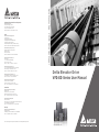
VFD-ED Series User Manual
Asia
Delta Elevator Drive
Industrial Automation Headquarters
Delta Elevator Drive
VFD-ED Series User Manual
Americas
Delta Products Corporation (USA)
Raleigh Office
P.O. Box 12173,5101 Davis Drive,
Research Triangle Park, NC 27709, U.S.A.
TEL: 1-919-767-3800 / FAX: 1-919-767-8080
Delta Greentech (Brasil) S.A
Sao Paulo Office
Rua Itapeva, 26 - 3° andar Edificio Itapeva One-Bela Vista
01332-000-São Paulo-SP-Brazil
TEL: +55 11 3568-3855 / FAX: +55 11 3568-3865
Europe
Deltronics (The Netherlands) B.V.
Eindhoven Office
De Witbogt 20, 5652 AG Eindhoven, The Netherlands
TEL: 31-40-2592850 / FAX: 31-40-2592851
*We reserve the right to change the information in this catalogue without prior notice.
www.deltaww.com
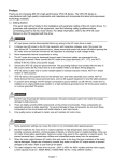
Preface
Thank you for choosing DELTA’s high-performance VFD-ED Series. The VFD-ED Series is manufactured with
high-quality components and materials and incorporates the latest microprocessor technology available.
This manual is to be used for the installation, parameter setting, troubleshooting, and daily maintenance of the AC
motor drive. To guarantee safe operation of the equipment, read the following safety guidelines before connecting
power to the AC motor drive. Keep this operating manual at hand and distribute to all users for reference.
To ensure the safety of operators and equipment, only qualified personnel familiar with AC motor drive are to do
installation, start-up and maintenance. Always read this manual thoroughly before using VFD-ED series AC Motor
Drive, especially the WARNING, DANGER and CAUTION notes. Failure to comply may result in personal injury
and equipment damage. If you have any question, please contact your dealer.
PLEASE READ PRIOR TO INSTALLATION FOR SAFETY.
DANGER!
1.
2.
3.
4.
5.
6.
7.
AC input power must be disconnected before any wiring to the AC motor drive is made.
A charge may still remain in the DC-link capacitors with hazardous voltages, even if the power has been turned
off. To prevent personal injury, please ensure that power has turned off before opening the AC motor drive and
wait ten minutes for the capacitors to discharge to safe voltage levels.
Never reassemble internal components or wiring.
The AC motor drive may be destroyed beyond repair if incorrect cables are connected to the input/output
terminals. Never connect the AC motor drive output terminals U/T1, V/T2, and W/T3 directly to the AC mains
circuit power supply.
Ground the VFD-ED using the ground terminal. The grounding method must comply with the laws of the country
where the AC motor drive is to be installed. Refer to the Basic Wiring Diagram.
VFD-ED series is used only to control variable speed of 3-phase induction motors, NOT for 1-phase motors or
other purpose.
VFD-ED series shall NOT be used for life support equipment or any life safety situation.
WARNING!
1.
2.
3.
DO NOT use Hi-pot test for internal components. The semi-conductor used in AC motor drive easily damage by
high-voltage.
There are highly sensitive MOS components on the printed circuit boards. These components are especially
sensitive to static electricity. To prevent damage to these components, do not touch these components or the
circuit boards with metal objects or your bare hands.
Only qualified persons are allowed to install, wire and maintain AC motor drives.
CAUTION!
1.
2.
3.
4.
5.
6.
Some parameters settings can cause the motor to run immediately after applying power.
DO NOT install the AC motor drive in a place subjected to high temperature, direct sunlight, high humidity,
excessive vibration, corrosive gases or liquids, or airborne dust or metallic particles.
Only use AC motor drives within specification. Failure to comply may result in fire, explosion or electric shock.
To prevent personal injury, please keep children and unqualified people away from the equipment.
When the motor cable between AC motor drive and motor is too long, the layer insulation of the motor may be
damaged. Please use a frequency inverter duty motor or add an AC output reactor to prevent damage to the
motor. Refer to appendix B Reactor for details.
The rated voltage for AC motor drive must be 240V ( 480V for 460V models) and the mains supply current
capacity must be 5000A RMS (10000A RMS for the 40hp (30kW) models)
Firmware version: 1.01
0-1
Ch01 Introduction
01 Introduction
1-1 Receiving and Inspection
After receiving the AC motor drive, please check for the following:
1) Inspect the unit after unpacking to assure it was not damaged during shipment. Make sure that the
part number printed on the package corresponds with the part number indicated on the nameplate.
2) Make sure that the voltage for the wiring lie within the range as indicated on the nameplate. Install the
AC motor drive according to this manual.
3) Before applying the power, make sure that all the devices, including power, motor, control board and
digital keypad, are connected correctly.
4) When wiring the AC motor drive, make sure that the wiring of input terminals “R/L1, S/L2, T/L3” and
output terminals”U/T1, V/T2, W/T3” are correct to prevent drive damage.
5) When power is applied, select the language and set parameter groups via the digital keypad
(KPED-LE01). When executing a trial run, begin with a low speed and then gradually increase the
speed untill the desired speed is reached.
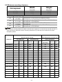
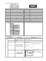
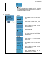
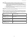
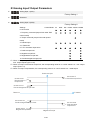
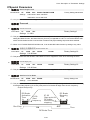
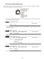
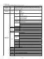
1-2 Nameplate Information
Using 15HP/11kW 230V, 3-Phase as an exemple.
AC Drive Model
Input Voltage/Current
Output Voltage/Current
Frequency Range
Firmware Version
MODEL
INPUT
OUTPUT
:VFD110ED23S
:3PH 180-264V 50/60Hz 47A
:3PH 0-240V 51.4A(LIFT DUTY)
45A(General)
11kW/15HP
Freq. Range :0-400Hz
Version: 0.01
Serial Number
110ED23SW14380001
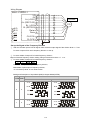
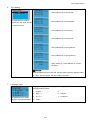
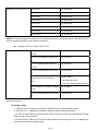
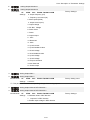
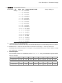
1-3 Model Name
1-4 Serial Number
VFD 110 ED 23 S
110ED23S W 14 38 0001
Version type
Production number
Input Voltage
23:230V 3-PHASE
43:460V 3-PHASE
Production week
T: Taoyuan , W:Wujiang
Ed series
230V 3-PHASE 15HP(11kW)
Appicable motor capacity
022:3HP(2.2kW)
220:30HP(22kW)
040:5HP(4.0kW)
300:40HP(30kW)
055:7.5HP(5.5kW) 370:50HP(37kW)
075:10HP(7.5kW)
450:60HP(45kW)
110:15HP(11kW)
550:75HP(55kW)
150:20HP(15kW)
750:100HP(75kW)
185:25HP(18.5kW)
Series name ( Variable Frequency Drive)
1-1
Production year
Production factory
Model number
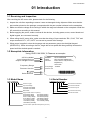
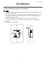
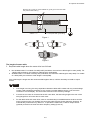
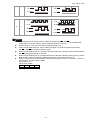
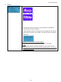
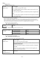
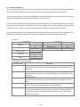
1-5 RFI Switch
The AC motor drive may emit the electrical noise. The RFI switch is used to suppress the interference
(Radio Frequency Interference) on the power line. The RFI Switch of Frame C, D, E are at similar position
(Frame B doesn’t have a RFI Switch). Open the top cover to remove the RFI switch as shown in the imge
below.
Frame E
RFI Switch
CAUTION
Incorrect
installation may result indamage to option
or inverter.Please refer to operation manual for
installation instructions.
警
錯誤的安裝將會導致變頻器及選配品損
壞,安裝前請務必參閱使用手冊後才進
行裝配。
1-2
告
Ch01 Introduction
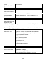
Isolating main power from ground:
When the power distribution system of the Power Regenerative Unit is a floating ground system (IT) or an
asymmetric ground system (TN), the RFI short-circuit cable must be cut off. Cutting off the short-circuit
cable also cuts off the internal RFI capacitor (filter capacitor) between the system's frame and the central
circuits to avoid damaging the central circuits and (according to IEC 61800-3) reduce the ground leakage
current.
Important points regarding ground connection
To ensure the safety of personnel, proper operation, and to reduce electromagnetic radiation, the
Power Regenerative Unit must be properly grounded during installation.
The diameter of the cables must meet the size specified by safety regulations.
The shielded cable must be connected to the ground of the Power Regenerative Unit to meet safety
regulations.
The shielded cable can only be used as the ground for equipment when the aforementioned points
are met.
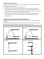
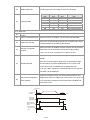
When installing multiple sets of Power Regenerative Units, do not connect the grounds of the Power
Regenerative Units in series. As shown below
Ground terminal
Best wiring setup for ground wires
Pay particular attention to the following points:
After turning on the main power, do not cut the RFI short-circuit cable while the power is on.
Make sure the main power is turned off before cutting the RFI short-circuit cable.
Cutting the RFI short-circuit cable will also cut off the conductivity of the capacitor. Gap discharge may
occur once the transient voltage exceeds 1000V.
If the RFI short-circuit cable is cut, there will no longer be reliable electrical isolation. In other words, all
controlled input and outputs can only be seen as low-voltage terminals with basic electrical isolation. Also,
when the internal RFI capacitor is cut off, the Power Regenerative Unit will no longer be electromagnetic
compatible.
The RFI short-circuit cable may not be cut off if the main power is a grounded power system.
The RFI short-circuit cable may not be cut off while conducting high voltage tests. When conducting a
high voltage test to the entire facility, the main power and the motor must be disconnected if leakage
current is too high.
1-3
Floating Ground System(IT Systems)
A floating ground system is also called IT system, ungrounded system, or high impedance/resistance
(greater than 30Ω) grounding system.
Disconnect the ground cable from the internal EMC filter.
In situations where EMC is required, check whether there is excess electromagnetic radiation
affecting nearby low-voltage circuits. In some situations, the adapter and cable naturally provide
enough suppression. If in doubt, install an extra electrostatic shielded cable on the power supply side
between the main circuit and the control terminals to increase security.
Do not install an external RFI/EMC filter, the EMC filter will pass through a filter capacitor, thus
connecting power input to ground. This is very dangerous and can easily damage the Power
Regenerative Unit.
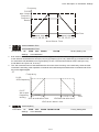
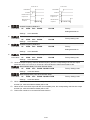
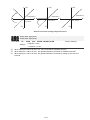
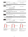
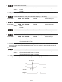
Asymmetric Ground System (Corner Grounded TN Systems)
Caution: Do not cut the RFI short-circuit cable while the input terminal of the Power Regenerative Unit
carries power.
In the following four situations, the RFI short-circuit cable must be cut off. This is to prevent the system
from grounding through the RFI capacitor, damaging the Power Regenerative Unit.
RFI short-circuit cable must be cut off
1. Grounding at a corner in a triangle configuration 2. Grounding at a midpoint in a polygonal
configuration
L1
L1
L2
L2
L3
L3
3. Grounding at one end in a single-phase
4. No stable neutral grounding in a three-phase
configuration
autotransformer configuration
L1
L1
L1
L2
L2
L3
N
L3
1-4
Ch01 Introduction
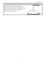
Use RFI short-circuit
Internal grounding through RFI capacitor, which reduces
L1
electromagnetic radiation. In a situation with higher
requirements for electromagnetic compatibility, and using a
symmetrical grounding power system, an EMC filter can be
installed. For example, the diagram on the right is a
symmetrical grounding power system.
L2
L3
1-5
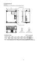
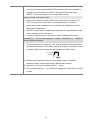
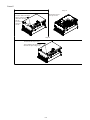
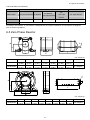
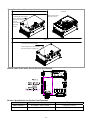
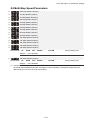
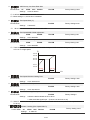
1-6 Dimensions
Frame B
VFD022ED21S, VFD037ED21S,VFD040ED23S/43S;
SEE DETAIL A
W
W1
D
H2
H
H1
D1
SEE DETAIL B
S1
S1
DETAIL A
(MOUNTING HOLE)
DETAIL B
(MOUNTING HOLE)
UNIT:mm[inch]
DIMENSIONAL
FRAME
W
W1
H
H1
H2
D
D1*
S1
B
193.5
[7.60]
162.5
[6.39]
260.0
[10.22]
247.0
[9.71]
230.0
[9.04]
133.5
[5.25]
58.0
[2.28]
6.5
[0.26]
*D1: This dimension is for flange mounting application reference.
1-6
Ch01 Introduction
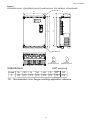
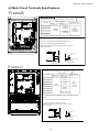
Frame C
VFD055ED23S/43S, VFD075ED23S/43S,VFD110ED23S/43S, VFD150ED43S, VFD185ED43S;
SEE DETAIL A
W
W1
D
H2
H1
H
D1
SEE DETAIL B
S1
S1
DETAIL A
(MOUNTING HOLE)
DETAIL B
(MOUNTING HOLE)
UNIT:mm[inch]
DIMENSIONAL
FRAME
W
W1
H
H1
H2
D
D1*
S1
C
235.0
[9.25]
204.0
[8.03]
350.0
[13.78]
337.0
[13.27]
320.0
[15.60]
146.0
[5.75]
70.0
[2.76]
6.5
[0.26]
*D1: This dimension is for flange mounting application reference.
1-7
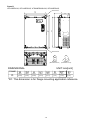
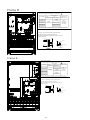
Frame D
VFD150ED23S, VFD185ED23S, VFD220ED23S/43S, VFD300ED43S;
SEE DETAIL A
W
W1
D1
H2
H1
H
D
SEE DETAIL B
S1
S1
DETAIL A
(MOUNTING HOLE)
DETAIL B
(MOUNTING HOLE)
UNIT:mm[inch]
DIMENSIONAL
FRAME
W
W1
H
H1
H2
D
D1*
S1
D
255.0
[10.04]
226.0
[8.90]
403.8
[15.90]
384.0
[15.12]
360.0
[14.17]
178.0
[7.01]
94.0
[3.70]
8.5
[0.33]
*D1: This dimension is for flange mounting application reference.
1-8
Ch01 Introduction
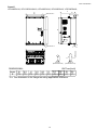
Frame E
VFD300ED23S, VFD370ED23S/43S, VFD450ED43S, VFD550ED43S, VFD750ED43S;
D
W
W1
D1
D2
H2
H
H1
SEE DETAIL A
S2
SEE DETAIL B
S1
S1
DETAIL A
(MOUNTING HOLE)
DETAIL B
(MOUNTING HOLE)
UNIT:mm[inch]
DIMENSIONAL
FRAME
W
W1
H
H1
H2
D
D1*
D2
S1
S2
330.0
[12.99]
285.0
[11.22]
550.0
[21.65]
525.0
[20.67]
492.0
[19.37]
273.4
[10.76]
107.2
[4.22]
16.0
[0.63]
11.0
[0.43]
18.0
[0.71]
E
*D1: This dimension is for flange mounting application reference.
1-9
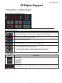
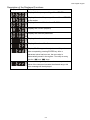
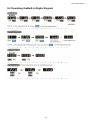
Bulilt-in Digital Keypad
KPED-LE01
1-10
Ch02 Installation
02 Installation
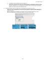
2-1 Minimum Mounting Clearance and Installation
NOTE
Prevent fiber particles, scraps of paper, shredded wood saw dust, metal particles, etc. from
adhereing to the heat sink
Install the AC motor drive in a metal cabinet. When installing one drive below another one,
use a metal separation between the AC motor drives to prevent mutual heating and to
prevent the risk of fire accident.
Install the AC motor drive in Pollution Degree 2 environments only: normallyl only
nonconductive pollution occurs and temporary conductivity caused by condensation is
expected.
The image below is for reference only.
Air Flow
H
W
W
H
2-1
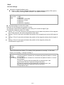
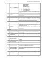
2-2 Minimum mounting clearance
Horsepower
3-5HP
7.5-20HP
25-30HP
Frame
B
C
D
E
Width
Height
mm (inch)
mm (inch)
50 (2)
75 (3)
75 (3)
150 (6)
175 (7)
200 (8)
Capacity
Model No.
3.0-5.0HP
(2.2-4kW)
7.5-15HP
(5.5-11kW)
20-40HP
(15-30kW)
40-100HP
(30-75kW)
VFD022ED21S, VFD037ED21S,VFD040ED23S/43S
VFD055ED23S/43S, VFD075ED23S/43S,VFD110ED23S/43S,
VFD150ED43S, VFD185ED43S
VFD150ED23S, VFD185ED23S, VFD220ED23S/43S
VFD300ED43S
VFD300ED23S, VFD370ED23S/43S, VFD450ED43S,
VFD550ED43S, VFD750ED43S
NOTE
The minimum mounting clearances stated in the table above applies to AC motor drives frame B,C,D and E. A
drive which fails to follow the minimum mounting clearances may cause the fan to malfunction and heat
dissipation problem.
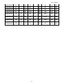
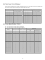
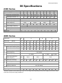
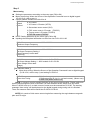
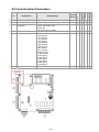
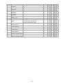
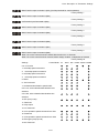
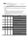
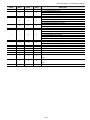
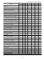
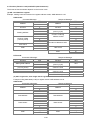
Air flow rate for cooling
Model No.
Flow Rate(cfm)
Power Dissipation AC motor drive
Flow Rate(m3/hr)
Power Dissipation
External
Internal
Total
External
Internal
Total
VFD022ED21S
13.7
-
13.7
23.3
-
23.3
VFD037ED21S
23.9
-
23.9
40.7
-
VFD040ED23S
23.9
-
23.9
40.7
VFD055ED23S
48.5
-
48.5
VFD075ED23S
48.5
-
VFD110ED23S
47.9
VFD150ED23S
Loss External
Internal
Total
60
36
96
40.7
84
46
130
-
40.7
133
49
182
82.4
-
82.4
212
67
279
48.5
82.4
-
82.4
292
86
379
-
47.9
81.4
-
81.4
355
121
476
64.6
-
64.6
109.8
-
109.8
490
161
651
VFD185ED23S
102.3
-
102.3
173.8
-
173.8
638
184
822
VFD220ED23S
102.8
-
102.8
174.7
-
174.7
723
217
939
VFD300ED23S
179
30
209
304
51
355
932
186
1118
VFD370ED23S
179
30
209
304
51
355
1112
222
1334
VFD040ED43S
13.7
-
13.7
23.3
-
23.3
123
42
165
VFD055ED43S
48.5
-
48.5
82.4
-
82.4
185
55
240
VFD075ED43S
48.5
-
48.5
82.4
-
82.4
249
71
320
VFD110ED43S
47.9
-
47.9
81.4
-
81.4
337
94
431
2-2
(Heat Sink)
Ch02 Installation
VFD150ED43S
46.1
-
46.1
78.4
-
78.4
302
123
425
VFD185ED43S
46.1
-
46.1
78.4
-
78.4
391
139
529
VFD220ED43S
102.8
-
102.8
174.7
-
174.7
642
141
783
VFD300ED43S
83.7
-
83.7
142.2
-
142.2
839
180
1019
VFD370ED43S
179
30
209
304
51
355
803
252
1055
VFD450ED43S
179
30
209
304
51
355
1014
270
1284
VFD550ED43S
179
30
209
304
51
355
1244
275
1519
VFD750ED43S
186
30
216
316
51
367
1541
338
1878
2-3
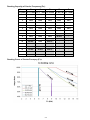
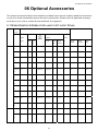
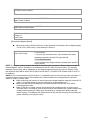
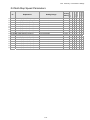
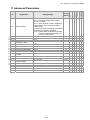
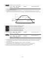
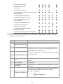
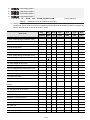
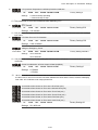
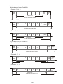
Derating Capacity of Carrier Frequency (Fc):
Frame
B
C
D
E
E
Fc(kHz) 2.2~4 kW 5.5~11 kW 15~22 kW 30~45 kW 55~75kW
0
100%
100%
100%
100%
100%
1
100%
100%
100%
100%
100%
2
100%
100%
100%
100%
100%
3
100%
100%
100%
100%
100%
4
100%
100%
100%
100%
100%
5
100%
100%
100%
100%
100%
6
100%
100%
100%
100%
100%
7
100%
100%
100%
90.73%
-
8
100%
100%
100%
82.20%
-
9
94.24%
100%
92.32%
74.31%
-
10
88.92%
100%
85.21%
-
-
11
82.54%
95.35%
78.63%
-
-
12
78.08%
91.02%
72.53%
-
-
13
73.95%
86.98%
66.87%
-
-
14
70.14%
84.14%
61.62%
-
-
15
66.61%
80.67%
56.74%
-
-
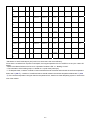
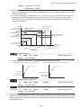
Derating Curve of Carrier Freuqncy (Fc):
2-4
Ch02 Installation
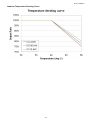
Ambient Temperature Derating Curve:
2-5
Ch03 Wiring
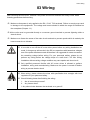
03 Wiring
After removing the front cover, examine if the power and control terminals are clearly noted. Read
following precautions before wiring.
Make sure that power is only applied to the R/L1, S/L2, T/L3 terminals. Failure to comply may result
in damage to the equipments. The voltage and current should lie within the range as indicated on
the nameplate (Chapter 1-1).
All the units must be grounded directly to a common ground terminal to prevent lightning strike or
electric shock.
Make sure to fasten the screw of the main circuit terminals to prevent sparks which is made by the
loose screws due to vibration
It is crucial to turn off the AC motor drive power before any wiring installation are
made. A charge may still remain in the DC bus capacitors with hazardous voltages
DANGER
even if the power has been turned off therefore it is suggested for users to measure
the remaining voltage before wiring. For your personnel saftery, please do not
perform any wiring before the voltage drops to a safe level < 25 Vdc. Wiring
installation with remaninig voltage condition may caus sparks and short circuit.
Only qualified personnel familiar with AC motor drives is allowed to perform
installation, wiring and commissioning. Make sure the power is turned off before
wiring to prevent electric shock.
When wiring, please choose the wires with specification that complys with local
regulation for your personnel safety.
Check following items after finishing the wiring:
1.
Are all connections correct?
2.
Any loosen wires?
1. Any short-circuits between the terminals or to ground?
3-1
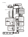
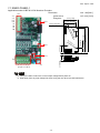
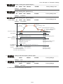
3-1 Wiring
DC choke (optional)
Jumper
Brake resistor
(optional)
*1
EPS
Providing
3-phase power
No-Fuse
Breaker
+
R/L1
R/L1
-
+1 +2/B1
B2
U/T1
Motor
M
3~
S/L2
S/L2
V/T2
T/L3
T/L3
W/T3
24V Power Input
Factory setting: NPN(SINK) Mode
Refer to figure 1 for wiring of NPN &
PNP mode
FWD/STOP
U24V
RA
RB
+24V
RC
COM
REV
MRA
MRB
MRC
MI1
R1A
MI2
R2A
R12C
FWD
REV/STOP
Multi-step 1
Multi-step 2
Multi-step 3
MI3
Multi-step 4
Factory
setting
MI4
N/A
MI5
N/A
N/A
Safety Circuit
Feedback
Multifunction
Input
Terminal
Multi-funciton output terminal
3 A(N.O.)/3A(N.C.) 250VAC
5A(N.O.)/3A(N.C.) 30VDC
Factory setting: No function
RS485
SG1+
SG1-
MI6
DCM
MI7
CAN_L
CAN_H
comm.
control
CAN
comm.
control
DCM
It is aNshort
OTE circuiting jumper installed between
DCM,SCM1 and SCM2 when this motor drive
leaves the factory. Remove this short circuiting
jumper before using the safety function while wiring
Multi-function output
MO1 frequency terminal
4 8V /50 mA
Multi-function output
MO 2 frequency terminal
4 8V /50 mA
MCM Multi-function
Photocoupler Output
Terminal
.
It is a short circuiting jumper installed between
+24V,STO1 and STO2 when this motor drive
leaves the factory. Remove this short circuiting
jumper before using the safety function while wiring
+2 4V DC
E STO P
Factory setting: Motor drive is in operation
MI8
Digital Signal
Common Terminal
*2)
Multi-funciton output terminal
3 A(N.O.)/3A(N.C.) 250VAC
5A(N.O.)/3A(N.C.) 30VDC
Factory setting: fault alert
Multi-funciton output terminal
3A(N.O.)/3A(N.C.) 250VAC
5A(N.O.)/3A(N.C.) 30VDC
*1
DCM
SCM1
Multi-fucntion
Analog Output Terminal
SCM2
Safety PLC
*2
-10~ +10V
E24 V
Analog Signal
Common Terminal
Multi-fucntion
Analog Output Terminal
STO 1
STO 2
+10 V/2 0mA
-10~ +10V
+10 V
8
1
-10 ~+10V
AUI1
- 10 ~+1 0V
Analog Signal
Common Terminal
- 10 V/20 mA
AUI2
A CM
Modbus RS485
SG+ PIN 1, 2, 6, 7:Reserved
PIN 3:GND
SG-
4: SGPIN 5:SG+
PIN8:EV
- 10 V
USB port
open
CAN
120
open
Factory
Setting SG+
120
Factory
Setting
120
120
PRG
SW2
NRM
PG card
Expansion slot
Factory
Setting
NRM
3-2
Ch03 Wiring
Figure 01
Switching bwtween two modes: SINK(NPN) /SOURCE(PNP)
Sourc e Mode
w ith internal power (+24VD C)
MI1
MI1
MI2
MI2
~
2
~
1 Sink Mode
with internal power (+24VDC )
MI8
MI8
+2 4V
DCM
COM
COM
DCM
internal c irc ui t
3 Sink Mode
with external power
+2 4V
4 Sourc e Mode
with external power
MI2
MI2
~
MI1
~
MI1
MI8
MI8
+2 4V
+2 4V
COM
COM
DCM
external power +24V
internal c irc ui t
DCM
internal c irc ui t
external pow er +24V
3-3
internal c irc ui t
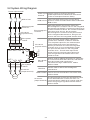
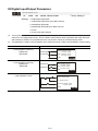
3-2 System Wiring Diagram
Power input terminal
Supply power according to the rated
Power input
power specifications indicated in the manual
terminal
(refer to Ch08 Specifications Table).
NFB or fuse
Electromagnetic
contactor
AC reactor
(input terminal)
There may be a large inrush current during
NFB or fuse power on. Refer to Ch06 NFB to select a suitable
NFB or fuse.
Switching ON/OFF the primary side of the
electromagnetic contactor can turn the integrated
elevator device ON/OFF, but frequent switching is
Electromagnetic a cause of machine failure. Do not switch ON/OFF
more than once an hour. Do not use the
contactor
electromagnetic contactor as the power switch
for the integrated elevator drive; doing so will
shorten the life of the integrated elevator drive.
EMI filter
BR
VFDB Brake Module
BR
Zero-phase
reactor
R/L1 S/L2 T/L3 E
+
B1
B2
U/T1 V/T2 W/T3
E
Zero-phase
reactor
Brake
Resistor
AC reactor
(input terminal)
Used to reduce radiated interference, especially
in environments with audio devices, and reduce
Zero-phase
input and output side interference.
reactor
The effective range is AM band to 10MHz.
Refer to Ch06.
EMI filter
AC reactor
(output terminal)
Motor
When the main power supply capacity is
greater than 1000kVA, or when it switches
into the phase capacitor, the instantaneous
peak voltage and current generated will
destroy the internal circuit of the integrated
elevator drive. It is recommended to install
an input side AC reactor in the integrated
elevator drive. This will also improve the
power factor and reduce power harmonics.
The wiring distance should be within 10m.
Refer to Ch06
Can be used to reduce electromagnetic
interference.
Brake resistor Used to shorten deceleration time of the motor.
Refer to Ch06.
The wiring length of the motor will affect the size
of the reflected wave on the motor end. It is
AC reactor
(output terminal) recommended to install an AC reactor when the
motor wiring length is greater than 20 meters.
Refer to Ch06.
3-4
Ch04 Main Circuit Terminals
04 Main Circuit Terminals
4-1 Main Circuit Diagram
DC reactor(optional)
Provide
3-phase
input power
R/L1
NFB
(No Fuse Breaker)
Jumper
*1
EPS
+
R/L1
-
Brake resistor (optional)
+1 +2/B1
B2
U/T1
Motor
M
3~
S/L2
S/L2
V/T2
T/L3
T/L3
W/T3
Terminal Symbol
EPS(+,-)
Explanation of Terminal Function
Backup power/ Emergency power connection terminal.
R/L1, S/L2, T/L3 AC line input terminals 3-phase.
U/T1, V/T2, W/T3 AC drive output terminals for connecting 3-phase induction motor.
Connections for DC reactor to improve the power factor. Remove the jumper
before installing a DC reactor. (Frame E has a DC reactor built-in.).
Connections for brake resistor (optional).
+1, +2/B1
+2/B1, B2
Earth connection, to comply with local regulations.
E
Main input power terminals:
Do not connect 3-phase model to one-phase power. R/L1, S/L2 and T/L3 has
no phase-sequence requirement, it can be used upon random selection.
A NFB must be installed between the 3-phase power input terminals and the
main circuit terminals (R/L1, S/L2, T/L3). It is recommended to add a
magnetic contactor (MC) to the power input wiring to cut off power quickly
and reduce malfunction when activating the protection function of the AC
motor drive. Both ends of the MC should have an R-C surge absorber.
Fasten the screws in the main circuit terminal to prevent sparks condition
made by the loose screws due to vibration.
Use voltage and current within the specification in Chapter 8.
When using a general GFCI (Ground Fault Circuit Interrupter), select a
current sensor with sensitivity of 200mA or above and not less than
0.1-second operation time to avoid nuisance tripping. When choosing a GFCI
designed for the AC motor drive, choose a current sensor with sensitivity of
30mA or above.
Use the shield wire or tube for the power wiring and ground the two ends of
the shield wire or tube.
4-1
Do NOT run/stop AC motor drives by turning the power ON/OFF. Run/stop
AC motor drives by sending RUN/STOP command via control terminals or
keypad. If you still need to run/stop AC motor drives by turning power
ON/OFF, it is recommended to do so only ONCE per hour
Output terminals of the main circuit:
When it is necessary to install a filter at the output side of terminals U/T1,
V/T2, W/T3 on the AC motor drive. Use inductance filter. Do not use
phase-compensation capacitors or L-C (Inductance-Capacitance) or R-C
(Resistance-Capacitance).
DO NOT connect phase-compensation capacitors or surge absorbers at the
output terminals of AC motor drives.
Use well-insulated motors to prevent any electric leakage from motors.
Terminals [+1, +2] for connecting DC reactor. Terminals [+1, +2/B1] for
connecting brake resistor.
These terminals are to connect to a DC reactor to improve the power factor
and reduce harmonics. At the factory setting, a jumper is connected to these
terminals.. Remove that jumper before connecting to a DC reactor.
DC reactor
Jumper
+1
Models above 22kW don’t have a built-in brake resistor. To improve
resistance ability, connect an external, optional brake resistor
When not in use, leave terminals +2/B1, (-) open.
Short-circuiting [B2] or [-] to [+2/B1] will damage the motor drive. Do NOT
do that.
4-2
Ch04 Main Circuit Terminals
4-2 Main Circuit Terminals Specifications
FrameB
:
R/L1,S/L2,T/L3,U/T1,V/T2/,WT3,+(DC+),-(DC-),B1 ,B2,
Wire Gauge
Models
Max.
Wire Gauge
Min.
Wire Gauge
VFD022ED21S
VFD040ED43S
10AWG
[ 5.3mm2]
VFD037ED21S
VFD040ED23S
Screw Size &
Torque (? 0%)
14AWG
[ 2.1mm2]
M4
18 kgf-cm
(15.6 lbf-in)
(1.7 Nm)
12AWG
[ 3.3mm2]
UL installations must use 600V, 75 ? wire. Use copper wire only.
NOTE:
1. Figure 1 shows the terminal specification.
DC+
DC-
B1 B2
U/T1 V/T2 W/T3
MOTOR
2. Figure 2 shows the specification of
insulated heat shrink tubing that comply with UL
(600V, YDPU2).
6 Max.
R/L1 S/L2 T/L3
POWER
8.5 Max
13 min.
4.2 Min.
Ring lug
Ring lug
Heat Shrink Tube
13 Max.
8.5 Max
WIRE
Figure 2
Figure 1
Frame C
Main circuit
: terminals:
R/L1,S/L2,T/L3,U/T1,V/T2/,WT3,+1,+2/B1,-,B2,
Models
Wire Gauge
Max.
Wire Gauge
VFD055ED23S
10AWG
[ 3.3mm2 ]
VFD110ED43S
VFD055ED43S
VFD075ED43S
VFD075ED23S
Screw Size &
Torque (? 0%)
Min.
Wire Gauge
6AWG
[ 13.3mm2 ]
M5
30 kgf-cm
(26 lbf-in)
(2.9 Nm)
12AWG
[ 3.3mm2 ]
8AWG
[ 8.4mm2 ]
VFD150ED43S
VFD185ED43S
6AWG[ 13.3mm2 ]
VFD110ED23S
UL installations must use 600V, 75 ? wire.. Use copper wire only.
NOTE:
1. Figure 1 shows the terminal specification.
9 Max.
2. Figure 2 shows the specification of
insulated heat shrink tubing that comply with UL
(600V, YDPU2).
13 Max
13 min.
5.2 Min.
32 Max.
Ring lug
10 Max
Figure 1
4-3
Ring lug
Heat Shrink Tube
WIRE
Figure 2
Frame D
Main circuit
: terminals:
R/L1,S/L2,T/L3,U/T1,V/T2/,WT3,+1,+2/B1,-,B2,
Wire Gauge
Models
Min.
Wire Gauge
Max.
Wire Gauge
VFD150ED23S
Screw Size &
Torque (? 0%)
4AWG
[ 21.1mm2 ]
VFD300ED43S
2AWG
[ 33.6mm2 ]
VFD185ED23S
M6
50 kgf-cm
(43.4 lbf-in)
(4.9 Nm)
2]
6AWG[ 13.3mm2]
2AWG[ 33.6mm2 ]
3AWG[ 26.7mm
VFD220ED43S
VFD220ED23S
UL installations must use 600V, 75 ? wire. Use copper wire only.
NOTE:
1. Figure 1 shows the terminal specification.
9 Max.
2. Figure 2 shows the specification of
insulated heat shrink tubing that comply with UL
(600V, YDPU2).
17 Max
13 min.
6.2 Min.
Ring lug
Ring lug
Heat Shrink Tube
32 Max.
14 Max
WIRE
Figure 2
Frame E
Main circuit
: terminals:
R/L1,S/L2,T/L3,U/T1,V/T2/,WT3,+1(DC+),-(DC-),
Models
Wire Gauge
Max.
Wire Gauge
VFD370ED43S
2/0AWG[ 67.4mm2 ]
VFD450ED43S
VFD300ED23S
Screw Size &
Min.
Torque (? 0%)
Wire Gauge
1/0AWG[ 53.5mm2 ]
300MCM
[ 152mm2 ]
VFD550ED43S
VFD370ED23S
4/0AWG
[ 107mm2 ]
M8
200 kgf-cm
(173 lbf-in)
(19.6 Nm)
300MCM
[ 152mm2]
VFD750ED43S
UL installations must use 600V, 75 ? wire. Use copper wire only.
NOTE:
1. Figure 1 shows the terminal specification.
17 Max.
2. Figure 2 shows the specification of
insulated heat shrink tubing that comply with UL
(600V, YDPU2).
28 Max
13 min.
8.2 Min.
48 Max.
Ring lug
28 Max
Figure 1
4-4
Ring lug
Heat Shrink Tube
WIRE
Figure 2
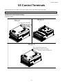
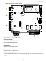
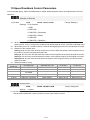
Control Terminals
05 Control Terminals
Remove the top cover before wiring the multi-function input and output terminals
The motor drives’ fiugres shown below are for reference only, the real motor drives may look different.
Remove the cover before wiring
Frame B, C & D:
Step 2
Step1
Loosen the 4screws.
Step 3
Put back the top cover.
Then fasten the 4 screws,
Screw torque 15kgf-cm
5-1
Frame E
Step 2
Step 1
Motor drive w/o
the top cover.
Loosen the 2 screws,
Then follow the
direction of the
arrow
to remove
the top
cover
Step 3
Put back the top cover.
Then fasten the 2 screws.
Screw torque:15kgf-cm
5-2
Control Terminals
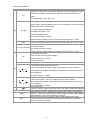
Specifications of the Control Terminal
Control Circuit Terminal Sockets:
Terminal sockets A, B, C
Torque force: 2kg-cm [1.7lb-in.] (0.20Nm)
Wire gauge: 28~14AWG[0.08~2.07mm²]
Terminal socket D:
Torque force: 2kg-cm [1.7lb-in.] (0.20Nm)
Terminal socket E:
Torque force: 5.2kg-cm [4.5lb-in.] (0.51Nm)
Wire gauge: 28~12AWG[0.08~3.33mm²]
To comply with UL standards, copper wires which are able to sustain 600V, 75ºC environment must be used in the
installation.
5-3
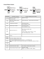
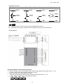
Control Board Switch
Factory
Setting
Terminals
+24V/E24V
COM
Factory
Setting
Terminal Function
Digital control signal common
Factory
Setting
Factory Setting (NPN mode)
+24V±5% 200mA
terminal (Source)
Digital control signal common
Common terminal of multi-function input terminals
terminal (Sink)
FWD
Forward-Stop command
REV
Reverse-Stop command
FWD-DCM:
ON= forward running
OFF= deceleration to stop
REV-DCM:
ON= forward running
OFF= deceleration to stop
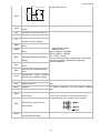
Refer to parameters 02-01~02-08 to program the
MI1
~
MI8
multi-function inputs MI1~MI8.
Multi-function input 1~8
Source mode:
ON: the activation current is 6.5mA≧11Vdc
OFF: cut-off voltage 10μA ≦11Vdc
DCM
Digital frequency signal common
terminal
SCM1
SCM2
STO1
The factory setting is short-circuit.
The factory setting is short-circuit.
Power removal safety function for EN954-1 and IEC/EN61508
When STO1~SCM1, STO2~SCM2 are turned on, the activation current is 3.3mA ≧
11Vdc.
STO2
+10V
Potentiometer power supply
Power supply of analog frequency setting: +10Vdc 20mA
-10V
Potentiometer power supply
Power supply of analog frequency setting
AUI1
Analog voltage frequency input
Impedance: 20kΩ
Range: -10~+10VDC=0~ Max. Output
5-4
Control Terminals
+10V AUI circuit
Frequency(Pr.01-00)
AUI
AUI2
ACM
internal circuit
ACM
Analog signal common terminal Analog sigal terminal
control
RA
Multi-function relay output A (N.O.)
RB
Multi-function relay output A (N.O.)
RC
MRA
MRB
MRC
R1A
R2A
R12C
Multi-function relay output B (Eror
indication by factory setting)
Multi-function output terminal
(N.O.)
1. User-defined funcion
2. Resistive Load
(N.O.)
3A(N.O.)/3A(N.C.) 250VAC
5A(N.O.)/3A(N.C.) 30VDC
Multi-function output terminal
(min. 5 VDC, 10 mA)
(Operating Indication by factory To output different kinds of signal such as the motor
drive is in operation, reaching the frequency,
setting)
overload indication.
Multi-function output terminal A
Multi-function output terminal
(N.O.)
Multi-function output terminal A
(N.O.)
Multi-function
output
terminal
(No function by factory setting)
SG1+
Modbus RS-485
SG1+ switch: terminator 120 ohm (factory setting) /
SG1-
Modbus RS-485
open
CAN_L
CAN Bus
DIP Switch: terminator 120 ohm (factory setting)/
CAN_H
CAN Bus
open
Multi-function output terminal 1
The AC motor drive releases various monitoring signals,
(photocoupler)
such as drive in operation, reaching frequency and
MO1
overload indication via a transistor (open collector).
MO2
MCM
Multi-function output terminal 2
(photocoupler)
Multi-function output common
Max 48Vdc 50mA
terminal (photocoupler)
5-5
0~10V, Max. output current: 2mA, Max. load: 5kΩ
-10~10V, Max. output current: 2mA, Max.load :5kΩ
Output current 2mA max
AFM1
Resolution 0~10V corresponds to the Max.operating
frequency.
Range: 0~10V→-10~+10V
0~10V, Max. Output current: 2mA, Max. load: 5Kω
-10~10V, Max. output current: 2mA, Max. load: 5kΩ
Output current:: 2mA max
AFM2
Resolution: 0~10V corresponds to the Max.operating
frequency.
Range: 0~10V→-10~+10V
RJ-45
SW2
PIN 1,2,6,7 : Reserved
PIN 4: SGSwitching USB port
PIN 3: SGND
PIN 5: SG+
PIN 8: EV
DIP Switch: NRM(factory setting)/ PRG
5-6
06 Optional Accessories
06 Optional Accessories
The optional accessories listed in this chapter are available upon request. Installing additional accessories
to your drive would substantially improve the drive’s performance. Please select an applicable accessory
according to your need or contact the local distributor for suggestion.
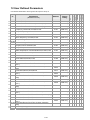
6-1 Brake Reistors & Brake Units used in AC motor Drives
Voltage
Applicable
*125% Braking Torque /10%ED
**Max. Brake Torque
Motor
Model
***Braking
Brake Unit
Torque
(kg-m)
VFDB
Resistor
value
spec. for
each
AC motor
Drive
Quan-
Braking Resistor series for each
Braking
Brake Unit
Current
****Part#
tity
230V
VFD022ED
Quan-
Wiring
tity
method
(A)
Min.
Resistotr
Value(Ω)
Max. Total
Braking
Current(A)
Peak
Power
(kW)
1.5
300W 70Ω
BR300W070
1
5.4
38.0
10
3.8
2.5
400W 40Ω
BR400W040
1
9.5
19.0
20
7.6
2.5
400W 40Ω
BR400W040
1
9.5
19.0
20
7.6
3.7
1000W 20Ω
BR1K0W020
1
19
15.6
24
9.3
5.1
1500W 13Ω
BR1K5W013
1
29
11.5
33
12.5
7.5
1500W 13Ω
BR1K5W013
1
29
9.5
40
15.2
10.2
2000W 8.6Ω
BR1K0W4P3
2
2 serial
44
8.3
46
17.5
12.2
2400W 7.8Ω
BR1K2W3P9
2
2
49
5.8
66
25.1
14.9
3000W 6.6Ω
BR1K5W3P3
2
2 serial
58
5.8
66
25.1
21S
VFD037ED
21S
VFD040ED
23S
VFD055ED
23S
VFD075ED
23S
VFD110ED
23S
VFD150ED
23S
VFD185ED
serial
23S
VFD220ED
23S
VFD300ED
20.3
2015
2
4000W 5.1Ω
BR1K0W5P1
2
2 serial
75
4.8
80
30.4
25.1
2022
2
4800W 3.9Ω
BR1K2W3P9
2
2 serial
97
3.2
120
45.6
2.7
1000W 75Ω
BR1K0W075
1
10.2
54.3
14
10.6
3.7
1000W 75Ω
BR1K0W075
1
10.2
48.4
16
11.9
23S
VFD370ED
23S
460V
VFD040ED
43S
VFD055ED
43S
6-1
VFD075ED
5.1
1500W 43Ω
BR1K5W043
1
17.6
39.4
19
14.7
7.5
1500W 43Ω
BR1K5W043
1
17.6
42.2
18
13.7
10.2
2000W 32Ω
BR1K0W016
2
2 serial
24
25.0
30
23.1
12.2
3000W 26Ω
BR1K5W013
2
2 serial
29
20.8
37
27.7
14.9
3000W 26Ω
BR1K5W013
2
2serial
29
19.0
40
30..4
20.3
4000W 16Ω
BR1K0W016
4
2 parallel
2 serial
47.5
14.1
54
41.0
43S
VFD110ED
43S
VFD150ED
43S
VFD185ED
43S
VFD220ED
43S
VFD300ED
43S
VFD370ED
25.1
4045
1
4800W 15Ω
BR1K2W015
4
2parallel
2 serial
50
12.7
60
45.6
30.5
4045
1
6000W 13Ω
BR1K5W013
4
2 parallel
2 serial
59
12.7
60
45.6
37.2
4030
2
8000W 10.2Ω
BR1K0W5P1
4
4 serial
76
9.5
80
60.8
50.8
4045
2
9600W 7.5Ω
BR1K2W015
4
2 parallel
2 serial
100
6.3
120
91.2
43S
VFD450ED
43S
VFD550ED
43S
VFD750ED
43S
*Calculation of 125% brake toque: (kw)*125%*0.8; where 0.8 is the motor efficiency.
Since there is a resistor limit of power consumption, the longest operation time for 10%ED is 10 sec (On: 10sec/ Off:
90sec).
**Refer to the Brake Performance Curve for “Operation Duration & ED” vs. “Braking Current”.
***The calculation of the braking torque I s based on a 4-pole motor(1800 rpm).
****To dissipate heat, a resistor of 400W or lower should be fixed to the frame and maintain the surface temperature
below 250°C (482 °F); a resistor of 1000W and above should maintain the surface temperature below 600°C (1112
°F). If the surface temperature is higher than the temperature limit, install more heat dissipating system or incrase the
size of the resistor.
6-2
06 Optional Accessories
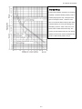
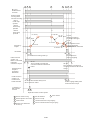
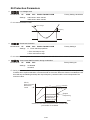
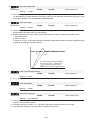
Thermal Relay:
Thermal relay selection is based on its overload
capability. A standard braking capacity of ED is
10%ED (Tripping time=10s). The figure on the
left is an example of 460V, 110kw AC motor
drive. It requires the thermal relay to take 260%
overload capacity for 10sec (hot starting) and
the braking current is 126A. In this case, user
should select a rated 50A thermal relay. The
property of each thermal relay may vary among
different manufacturers. Read carefully the user
guide of a thermal relay before using it. .
6-3
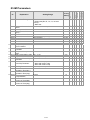
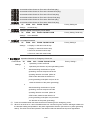
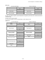
6-2 Non-fuse Circuit Brekaer
Comply with UL standard: Per UL 508, paragraph 45.8.4, part a. The rated current of a breaker shall
be 2~4 times of the maximum rated input current of AC motor drive.
3-phase
Model
Recommended
non-fuse breaker(A)
VFD022ED21S
50
VFD037ED21S
50
VFD040ED23S
40
VFD055ED23S
50
VFD075ED23S
60
VFD110ED23S
100
VFD150ED23S
125
VFD185ED23S
150
VFD220ED23S
175
VFD300ED23S
225
VFD370ED23S
250
3-phase
Model
VFD040ED43S
VFD055ED43S
VFD075ED43S
VFD110ED43S
VFD150ED43S
VFD185ED43S
VFD220ED43S
VFD300ED43S
VFD370ED43S
VFD450ED43S
VFD550ED43S
VFD750ED43S
Recommended
non-fuse breaker(A)
20
30
40
50
60
75
100
125
150
175
250
300
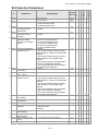
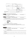
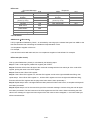
6-3 Fuse Specification Chart
Use only the fuses comply with UL certificated.
Use only the fuses comply with local regulations.
Model
Inuput Current (A) Output Current (A)
Line Fuse
VFD022ED21S
VFD037ED21S
VFD040ED23S
VFD055ED23S
VFD075ED23S
VFD110ED23S
VFD150ED23S
VFD185ED23S
VFD220ED23S
VFD300ED23S
VFD370ED23S
26
17
23
26
34
50
60
75
90
110
142
12
17
20
25
33
49
65
75
90
120
145
I (A)
50
50
40
50
60
100
125
150
175
225
250
VFD040ED43S
VFD055ED43S
VFD075ED43S
VFD110ED43S
VFD150ED43S
VFD185ED43S
VFD220ED43S
VFD300ED43S
VFD370ED43S
VFD450ED43S
VFD550ED43S
VFD750ED43S
13
14
19
25
32
39
49
60
63
90
130
160
11.5
13
18
24
32
38
45
60
73
91
110
150
50
30
40
50
60
75
100
125
150
175
250
300
6-4
Bussmann P/N
JJN-50
JJN-50
JJN-40
JJN-50
JJN-60
JJN-100
JJN-125
JJN-150
JJN-175
JJN-225
JJN-250
JJN-20
JJN-30
JJN-40
JJN-50
JJN-60
JJN-70
JJN-100
JJN-125
JJN-150
JJN-175
JJN-250
JJN-300
06 Optional Accessories
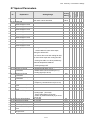
6-4 AC/ DCRactor
AC Input/ Output Reactor
200V~230V/ 50~60Hz (Single Phase Power)
Max.
3%
5%
Continuous
Built-in
impedance impedance
Amps
DC Reactor
(mH)
(mH)
(Arms)
Type
KW
HP
Rated
Amps
(Arms)
022
2.2
3
12
24
0.919
1.531
X
N/A
037
3.7
5
17
34
0.649
1.081
X
N/A
200V~230V/ 50~60Hz (Three-phase power)
Max.
3%
5%
Rated Amps Continuous
Built-in
Type KW HP
impedance impedance
(Arms)
Amps
DC Reactor
(mH)
(mH)
(Arms)
3% Input AC
reacotr
Delta Part#
3% Input AC
reacotr
Delta Part#
040
4
5
20
40
0.551
0.919
X
N/A
055
5.5
7.5
24
48
0.459
0.766
X
N/A
075
7.5
10
30
60
0.320
0.534
X
N/A
110
11
15
45
90
0.216
0.359
X
N/A
150
15
20
58
116
0.163
0.271
X
N/A
185 18.5 25
77
154
0.143
0.239
X
N/A
220
22
30
87
174
0.127
0.211
X
N/A
300
30
40
132
264
0.084
0.139
O
N/A
370
37
50
161
322
0.068
0.114
O
N/A
380V~460V/ 50~60Hz (Three-phase power)
Max.
3%
5%
Rated Amps Continuous
Built-in
Type KW HP
impedance impedance
(Arms)
Amps
DC Reactor
(mH)
(mH)
(Arms)
3% Input AC
reacotr
Delta Part#
040
4
5
11.5
23
1.838
3.063
X
N/A
055
5.5
7.5
13
26
1.626
2.710
X
N/A
075
7.5
10
17
34
1.243
2.072
X
N/A
110
11
15
23
46
0.919
1.531
X
N/A
150
15
20
30
60
0.704
1.174
X
N/A
18.5 25
38
76
0.556
0.927
X
N/A
185
220
22
30
45
90
0.470
0.783
X
N/A
300
30
40
58
116
0.364
0.607
X
N/A
370
37
50
80
160
0.264
0.440
O
N/A
450
45
60
100
200
0.211
0.352
O
N/A
550
55
75
121
242
0.175
0.291
O
N/A
750
75
100
146
292
0.145
0.241
O
N/A
6-5
DC Input/Output Reactor
200V~230V/ 50~60Hz (Three-phase power)
DC
DC
Reactor
Reactor
(Arms)
Max.
Continuous
Amps
(Arms)
(mH)
Delta Part#
Rated
Type
KW
HP
Amps
040
4
5
20
40
1.273
N/A
055
5.5
7.5
24
48
1.061
N/A
075
7.5
10
30
60
0.740
N/A
110
11
15
45
90
0.498
N/A
150
15
20
58
116
0.375
N/A
185
18.5
25
77
154
0.331
N/A
220
22
30
87
174
0.293
N/A
300
30
40
132
264
0.193
N/A
370
37
50
161
322
0.158
N/A
DC
DC
Reactor
Reactor
(Arms)
Max.
Continuous
Amps
(Arms)
(mH)
Delta Part#
380V~460V/ 50~60Hz(Three-phase power)
Rated
Type
KW
HP
Amps
040
4
5
11.5
23
4.244
N/A
055
5.5
7.5
13
26
3.754
N/A
075
7.5
10
17
34
2.871
N/A
110
11
15
23
46
2.122
N/A
150
15
20
30
60
1.627
N/A
185
18.5
25
38
76
1.284
N/A
220
22
30
45
90
1.085
N/A
300
30
40
58
116
0.842
N/A
370
37
50
80
160
0.610
N/A
450
45
60
100
200
0.488
N/A
550
55
75
121
242
0.403
N/A
750
75
100
146
292
0.334
N/A
6-6
06 Optional Accessories
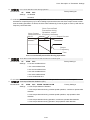
THD (Total Harmonic Distortion)
Motor Drive Spec.
Reactor Spec.
Without Built-In Reactor
3% Input AC Reactor DC Reactor
THD
Note:
44%
With Built-in DC Reactor
DC
DC Reactor
+ 3% Input Reactor
46%
+ 5% Input
34%
3% Input Reactor
Reactor
30%
34%
THD may varies due to different installation conditions and environment (wires, motors).
According to IEC61000-3-12, DC Reactor is designed with 4% system impedance, and AC Reactor is designed
with 3% system impedance.
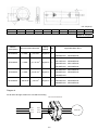
C
B
G
6-5 Zero Phase Reactor
D
A
F
E
unit: mm(inch)
Model
RF008X00A
RF004X00A
A
B
C
D
E
F
G(Ø)
98
(3.858)
110
(4.331)
73
(2.874)
87.5
(3.445)
36.5
(1.437)
43.5
(1.713)
29
(1.142)
36
(1.417)
56.5
(2.224)
53
(2.087)
86
(3.386)
96
(3.780)
5.5
(0.217)
5.5
(0.217)
Torque
8~ 10kgf/cm
8~ 10kgf/cm
C
H
B
G
F
D
E
unit: mm(inch)
model
RF002X00A
A
200
(7.874)
B
172.5
(6.791)
C
90
(3.543)
D
78
(3.071)
E
55.5
(2.185)
6-7
F
184
(7.244)
G(Ø)
5.5
(0.217)
H
22
(0.866)
Torque
40~45kgf/cm
unit: mm(inch)
model
A
B
C
D
E
F
G(Ø)
H
I
RF300X00A 241(9.488) 217(8.543) 114(4.488) 155(6.102) 42(1.654) 220(8.661) 6.5(0.256) 7.0(0.276) 20(0.787)
Torque:40~45kgf/cm
Reactor
model (Note)
Recommended Wire Size
RF008X00A
≦8 AWG
≦8.37 mm2
Wiring
Method
Qty
Diagram A
1
Applicable Motor Drive
VFD022ED21S VFD037ED21S
VFD040ED23S VFD040ED43S
VFD055ED23S VFD075ED23S
RF004X00A
≦4 AWG
≦21.15 mm2
Diagram A
1
VFD110ED23S VFD055ED43S
VFD075ED43S VFD110ED43S
VFD150ED43S VFD185ED43S
VFD150ED23S VFD185ED23S
RF002X00A
≦2 AWG
2
≦33.62 mm
Diagram A
1
VFD220ED23S VFD220ED43S
VFD300ED43S
VFD300ED23S VFD370ED23S
RF300X00A
≦300 MCM
≦152 mm
2
Diagram A
1
VFD370ED43S VFD450ED43S
VFD550ED43S VFD750ED43S
Note: 600V insulated cable wire
Diagram A
Put all wires through at least one core without winding
Zero Phase Reactor
R/L1
U/T1
S/L2
V/T2
T/L3
W/T3
MOTOR
6-8
06 Optional Accessories
Note 1: The table above gives approximate wire size for the zero phase reactors but the selection is ultimately
governed by the type and diameter of cable fitted i.e. the cable must fit through the center hole of zero phase
reactors.
Note 2: Only the phase conductors should pass through, not the earth core or screen.
Note3: When long motor output cables are used an output zero phase reactor may be required to reduce radiated
emissions from the cable.
6-9
6-6 EMI Filter
For the detailed specifications of the EMI filters listed in the table below, search the Internet.
Motor Drive
Applicable EMI Filter
VFD022ED21S VFD037ED21S
MDF50 (Roxburgh EMC)
VFD040ED43S VFD055ED43S
EMF018A43A
VFD075ED43S VFD110ED43S
EMF033A43A
VFD040ED23S VFD055ED23S
EMF035A23A
VFD075ED23S VFD110ED23S
EMF056A23A
VFD150ED43S
EMF039A43A
VFD185ED43S VFD220ED43S
KMF370A (Roxburgh EMC)
VFD150ED23S VFD185ED23S VFD300ED43S VFD370ED43S
KMF3100A (Roxburgh EMC)
VFD220ED23S VFD450ED43S VFD550ED43S
B84143D0150R127
VFD300ED23S VFD370ED23S VFD750ED43S
B84143D0200R127
EMI Filter Installation
All electrical equipment, including AC motor drives, will generate high-frequency/low-frequency noise and will
interfere with peripheral equipment by radiation or conduction when in operation. By using an EMI filter with correct
installation, much interference can be eliminated. It is recommended to use DELTA EMI filter to have the best
interference elimination performance.
We assure that it can comply with following rules when AC motor drive and EMI filter are installed and wired
according to user manual:
EN61000-6-4
EN61800-3: 1996
EN55011: (1991) Class A Group 1 (1st Environment, restricted distribution)
General precaution
1. EMI filter and AC motor drive should be installed on the same metal plate.
2. Install AC motor drive on footprint EMI filter or install EMI filter as close as possible to the AC motor
drive.
3. Wire as short as possible.
4. Metal plate should be grounded.
5. The cover of EMI filter and AC motor drive or grounding should be fixed on the metal plate and the
contact area should be as large as possible.
Choose suitable motor cable and precautions
Improper installation and choice of motor cable will affect the performance of EMI filter. Be sure to observe
the following precautions when selecting motor cable.
1. Use the cable with shielding (double shielding is the best).
2. The shielding on both ends of the motor cable should be grounded with the minimum length and
maximum contact area.
3. Remove any paint on metal saddle for good ground contact with the plate and shielding.
6-10
06 Optional Accessories
Remove any paint on metal saddle for good ground contact with
the plate and shielding.
saddle
the plate with grounding
Figure 1
Figure 2
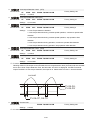
The length of motor cable
1. Required cable length when the motor drive is at full load.
a. Non-shielded cable: For models of 5.5kW(7.5HP) and below, the maximum cable length is 100m (328ft) . For
7.5kW(10HP) and above, the maximum cable length is 200m(656ft)
b. Shielded cable: For models of 5.5kw(7.5HP) and below, the maximum cable length is 50m(165ft). For models
of 7.5kW(10HP), the maximum cable length is 100m(328ft).
If the cable length is longer than the recommended lengthes above, it will be necessary to install an output
reactor.
NOTE
If the length is too long, the stray capacitance between cables will increase and may cause leakage
current. It will activate the protection of over current, increase leakage current or not insure the
correction of current display. The worst case is that AC motor drive may damage.
If more than one motor is connected to the AC motor drive, the total wiring length is the sum of the
wiring length from AC motor drive to each motor.
For the 460V series AC motor drive, when an overload relay is installed between the drive and the
motor to protect motor over heating, the connecting cable must be shorter than 50m. However, an
overload relay malfunction may still occur. To prevent the malfunction, install an output reactor
(optional) to the drive or lower the carrier frequency setting (Pr.00-12).
6-11
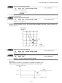
2. Consequence of the surge voltages on the motor
When a motor is driven by an AC motor drive of PWM type, the motor terminals will experience surge voltages easily
due to components conversion of AC motor drive and cable capacitance. When the motor cable is very long
(especially for the 460V series), surge voltages may reduce insulation quality. To prevent this situation, please follow
the rules below:
Use a motor with enhanced insulation.
Connect an output reactor (optional) to the output terminals of the AC motor drive
The length of the cable between AC motor drive and motor should be as short as possible (10 to 20 m or less)
For models 7.5hp and above:
Insulation level of motor
1000V
1300V
1600V
460VAC input voltage
20m(66ft)
100m(328ft)
400m(1312ft)
230VAC input voltage
400m(1312ft)
400m(1312ft)
400m(1312ft)
For models 5hp and less:
Insulation level of motor
1000V
1300V
1600V
460VAC input voltage
20m(66ft)
50m(165ft)
50m(165ft)
230VAC input voltage
100m(328ft)
100m(328ft)
100m(328ft)
NOTE
Never connect phase lead capacitors or surge absorbers to the output terminals of the AC motor drive.
6-12
06 Optional Accessories
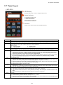
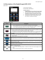
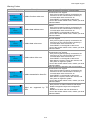
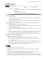
6-7 Digital Keypad
1 KPC-CE01
A : LED Disp lay
D ispla y freq uen cy, cu rre nt, vo ltag e and erro r etc.
: Status Indi cator
F: Fre que ncy C omma nd
H: Outp ut Frequ ency
U: User De fine d Uni ts
ERR: CAN Erro r Ind icator
RU N: CAN Ru n Indi ca tor
C : Function
(Re fer to the chart foll ow s for deta il de scripti on )
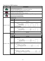
Key
Description
ESC
ESC Key
Press ESC key to return to the previous page. It also functions as a return to last category key in the sub-menu.
Menu Key
Press MENU key under any condition will return to the main MENU.
Menu content:
1. Parameter Detail
3. Keypad locked
2. Copy Parameter
4. PLC Function
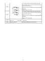
ENTER Key
Press ENTER and go to the next level. If it is the last level then press ENTER to execute the command.
HAND ON Key
1. HAND key will operates according to the parameter settings when the source of HAND master frequency
command and the source of HAND operation command is properly set,. The factory setting of the source
command for frequency and operation are from the digital keypad .
2. Press HAND key in stop status, the drive setting switches to the parameter setting of HAND. Press HAND
key in during operation, the drive will come to stop then switches to the parameter setting of HAND.
3. When process complete: H/A LED ON.
Auto Operation Key
1. AUTO function executes according to the parameter settings of the source of AUTO frequency and AUTO
operation. The factory setting is the external terminal (source of operation is 4-20mA).
2. Press the ATUO key in stop status, the drivel switches to auto-setting. Press the auto key during operation
status, the drivel will come to stop and switch to auto-setting.
3. When process complete: H/A LED is OFF
Operation Direction Key
1. FWD/REV key controls the operation direction but will NOT activate the drive. FWD: forward, REV: reverse.
2. The drive operates in the direction as shown by the LED light.
Start Key
1. This button is functional only when the keypad is the source of the command.
2. This button allows the motor drive to run by following its settings. See Description of LED functions for LED
status
3. Press repeatedly the “RUN” button is allow while the motor drive is stopping.
Stop Key.
1. STOP key has the highest priority in command.
2. Press STOP key, the drive will come to stop under any condition.
3. The RESET key can be used to reset the drive when faults occur. If the RESET key is not responding, check
MENU Fault Records and check the most recent fault.
MENU
ENTER
HAND
AUTO
FWD/REV
RUN
STOP
6-13
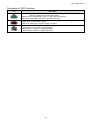
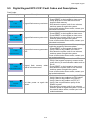
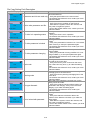
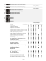
Descriptions of LED Functions
LED
Descriptions
Steady ON: operation indicator of the AC motor drive, including DC brake, zero speed, standby,
restart after fault and speed search.
Blinking: drive is decelerating to stop or in the status of base block.
Steady OFF: drive doesn’t execute the operation command
Steady ON: stop indicator of the AC motor drive.
Blinking: drive is in the standby status.
Steady OFF: drive doesn’t execute “STOP” command.
Operation Direction LED 『Green light= Forward』;
『Red light= Reversely』
Steady ON: the drive is running forward.
Blinking: the drive is changing direction.
Steady Off: the drive is running reversely.
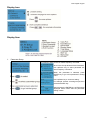
RUN (Green light):
LED
status
OFF
CANopen at initial
Condition/State
No LED
Blinking CANopen at pre-operation
CANopen ~”RUN”
Single
flash
ON
CANopen at stopped
CANopen at operation status
No LED
ERR (Red light):
LED
status
OFF
Single One message fail
flash
CANopen ~”ERR”
Double
flash
Triple
flash
Condition/ State
No Error
Guarding fail or heartbeat fail
SYNC fail
ON
Bus off
6-14
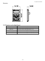
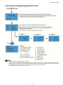
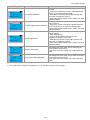
06 Optional Accessories
Dimension
RJ45 Extension Lead for Digital Keypad
Part #
Description
CBC-K3FT
3 feet RJ45 extension lead (approximately 0.9m)
CBC-K5FT
5 feet RJ45 extension lead (approximately 1.5 m)
CBC-K7FT
7 feet RJ45 extension lead (approximately 2.1 m)
CBC-K10FT
10 feet RJ45 extension lead (approximately 3 m)
CBC-K16FT
16 feet RJ45 extension lead (approximately 4.9 m)
6-15
6-8 USB/RS-485 Communication Interface IFD6530
Warning
Read thoroughly this section before installation and putting it into use.
The content of this section and the driver file may be revised without prior notice. Consult our distributors
or download the most updated instruction/driver version at
AC Motor Drive > Optional
Introduction
IFD6530 is a convenient RS-485-to-USB converter, which does not require external power-supply and complex
setting process. It supports baud rate from 75 to 115.2kbps and auto switching direction of data transmission. In
addition, it adopts RJ-45 in RS-485 connector for users to wire conveniently. And its tiny dimension, handy use of
plug-and-play and hot-swap provide more conveniences for connecting all DELTA IABU products to your PC.
Applicable Models: All DELTA IABU products.
Application & Dimension:
Specifications
Power supply
No external power is needed
Power consumption
1.5W
Isolated voltage
2,500VDC
Baud rate
75, 150, 300, 600, 1,200, 2,400, 4,800, 9,600, 19,200, 38,400, 57,600, 115,200 bps
RS-485 connector
RJ-45
USB connector
A type (plug)
Compatibility
Full compliance with USB V2.0 specification
Max. cable length
RS-485 Communication Port: 100 m
Support RS-485 half-duplex transmission
6-16
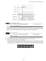
06 Optional Accessories
RJ-45
PIN
1
2
3
4
Description
Reserved
Reserved
GND
SG-
PIN
5
6
7
8
Description
SG+
GND
Reserved
+9V
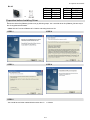
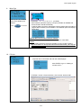
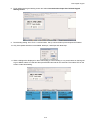
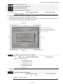
Prepration before Installing Driver
Extract the driver file (IFD6530_Drivers.exe) by following steps. You could find driver file (IFD6530_Drivers.exe) in
the CD supplied with IFD6530.
Note: DO NOT connect IFD6530 to PC before extracting the driver file.
STEP 1
STEP 2
STEP 3
STEP 4
STEP 5
You should have a folder marked SiLabs under drive C. c:\ SiLabs
6-17
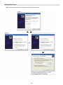
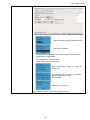
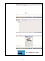
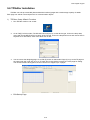
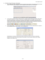
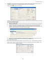
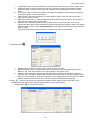
Intalling the Driver
After connecting IFD6530 to PC, install driver by following steps below.
6-18
06 Optional Accessories
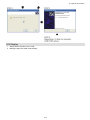
LED Display
1. Steady Green LED ON: power is ON.
2. Blinking orange LED: data is transmitting.
6-19
Ch07 Option Cards
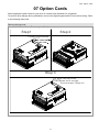
07 Option Cards
Select applicable option cards for your drive or contact local distributor for suggestion.
To prevent drive damage during installation, remove the digital keypad and the cover before wiring. Refer
to the following instruction.
Remove the top cover
Frame B, C & D
Screw Torque: Kg-cm [lb-in.]
Step 2
Step1
Loosen the 4screws.
Step 3
Put back the top cover.
Then fasten the 4 screws,
Screw torque 15kgf-cm
7-1
Frame E
Screw Torque: Kg-cm [lb-in.]
Step 2
Step 1
Motor drive w/o
the top cover.
Loosen the 2 screws,
Then follow the
direction of the
arrow
to remove
the top
cover
Step 3
Put back the top cover.
Then fasten the 2 screws.
Screw torque:15kgf-cm
Vertical viewe of the motor drive & Screw’s Specificatons:
Screws’ Specification for Option Card Terminal:
PG Card
Wire Gauge
EMED-PGABD-1
30~16AWG(0.05~1.31mm2)
EMED-PGHSD-1
Torque
2
30~16AWG(0.05~1.31mm )
7-2
1.6Kg-cm [1.4Ib-in]
1.6Kg-cm [1.4Ib-in]
Ch07 Option Cards
7-1 EMED-PGABD-1
Applicable enoder: A/B/Z & U/V/W Absolute Encoders
Dimension
TB2
unit:mm[inch.]
Dimension
Diagram
Vin
A/O
B/O
GND
AO
AO
BO
BO
unit: mm [inch]
53.0 [2.09]
47.0 [1.85]<2X>
SW3
15.5 [0.61]<2X>
]<3
30.0 [1.18]
.1
4]
19.0 [0.75]
X>
[Ø
0
SW1
A B Z U V W Vp
A B Z U V W 0V
21.9 [0.86]
TB1
JP1
NOTE
Verify if the SW1 is set to the correct output voltage before power on.
Keep away from any high voltage line when wiring the mtor drive to avoid interference.
7-3
109.0 [4.29]
.16
[Ø 0
SW2
105.0 [4.13]<2X>
.0
Ø4
Ø3
.5
Terminal Specification
Terminals
Descriptions
Terminal for voltage input, to adjust the amplitude of output voltage at terminal
Vin
A/O and terminal B/O. It also provdieds a 5V voltage to support line driver’s
signal.
Vin voltage range: 8~24V, Max: 24V.
Output signal of the push-pull frequency divider
Factory setting: Output amplitude is about +24V. Use SW2 to cut off the internal
default power. Input required power
TB2
A/O, B/O
(i.e. output voltage’s amplitude)
DVi voltage range Max:24V
(Push-Pull Voltage Output)
Max. output frequency: 100kHz
Support frequency dividing output, the frequency dividing range: 1~31Hz.
GND
Common ground terminal connecting to the host controller and the motor drive.
Line driver pulse output signal
(Line Driver RS422)
AO, /AO, BO, /BO
Max. output frequency: 150kHz
Support frequency dividing output, the frequency dividing range: 1~31Hz.
Power output of encoder
VP
Note: Use SW1 to set up output voltage
Voltage: +5V±0.5V or +12V±1V
Current: 200mA max
0V
Common power terminal of encoder
Incremental encoder signal input terminal
TB1
A、 A 、B、
B 、Z、 Z
Types of input signal: line drive, voltage output, push-pull, open-collector)
Note: Different input signal needs different wiring method. See user manual for
wiring diagrams.
Max.input frequency: 150kHz
U、 U 、V、
V 、W、 W
JP1
SW1
SW2
SW3
Absolute encoder signal input terminal
Types of input signal: : line drive, voltage, push-pull, open-collector)
Note: Different input signal needs different wiring method. See user manual for
wiring diagrams
Max.input frequency: 150kHz
Ground Terminal
Connect the power supply of the motor drive to the ground. Suport PG shielding
Switch between encoder’s 5V/12V power.
Offline Dectection Switch. Switch the the SW2 to Line-D side to enable offline
detection when Line-D input signal. Switch the SW2 to OPEN-C sideto disable
offline detection function when OPEN-C input signal.
Switch of power supply for frequency division Switch SW3 to INP_sied to
provide 24V power for internal use. Switch SW3 to EXP side to provide 24V
power for external use (client).
7-4
Ch07 Option Cards
Applicable encoders:
Push- pull
Different Types of Encoder Output
Voltage Output
Open collector
Line Driver
NOTE
Verify if the SW1 is set to the correct output voltage before power on.
Keep away from any high voltage line when wiring the mtor drive to avoid interference
Wiring Diagram
DC choke(optional)
Jumper
Brake resistor(optional)
Providing
3-phase power
Non‐Fuse Breaker
Motor
Encoder
Phase difference 90 ?
Phase difference 90 ?
Set up the Signal of the Frequency Division
① After the encoder input a PULSE signal, there will be an output signal of the division factor “n.” Use
Pr10-29 <Output of PG card’s frequency division> to set up.
② Setup of Pr10-29 <PG card’s frequency division>:
Output of decimal frequency division setting. Range of the division factor “n”: 1~31.
③ Pr10-30 <Mode of output of PG card’s frequency division>
Bit3
Bit2
Bit1
Bit0
X
X OUT/M IN/M
7-5
OUT/M: Mode of pulse output of frequency divsion;
IN/M: Mode of pulse input of frequency division;
“X” is for backup while “0” is a value to write.
Setting and Description of Input Mode (IN/M) & Output Mode(OUT/M):
Division factor
OUT/M
IN/M
A is ahead of B
0
0
1
0
X
B is ahead of A
A-/A
A-/A
B-/B
B-/B
AO-AO
A/O-/A/O
A/ O-/A/O
AO-AO
B/O-/B/O
BO-BO
BO-BO
B/O-/B/O
A-/A
A-/A
B-/B
B-/B
A/O-/A/O
A
O -A O
A/O-/A/O
AO-AO
B/O-/B/O
B
O -B O
B/O-/B/O
BO-BO
A-/A
A-/A
B-/B
B-/B
1
AO-AO
A/O-/A/O
A/O-/A/O
AO-AO
BO-BO
B/O-/B/O
B/O-/B/O
BO-BO
NOTE
In the waveform A-/A, B-/B are the PG card input signals; AO- AO , BO- BO are the differential
output frequency division signals. (Use a differential probe to measure.)
Division factor “n”: Set 15 to have the input signal divided by 15.)
When OUT/M, IN/M set as 0.0, the PG card input signal A-/A, B-/B are square waves while
AO- AO 、BO- BO are frequency division output.
When OUT/M, IN/M are set as 1.0, the PG card input signal A-/A、B-/B are square waves while the
BO- BO is the phase indicator of A and B
When OUT/M, IN/M are set as X, B-/B phase has to be direction indication input signal (e.g. When
B-/B is LOW, it means A is ahead of B. When B-/B is HIGH, it means B is ahead of A)
Take Pr10-29 and Pr10-30 as examples. When frequecy division value =1 5, OUT/M =1, IN/M = 0,
set Pr10-29 = 15 and Pr10-30 = 0002h.
Set Pr100-29 =15,
Set Pr10-30 =0002h
Bit3 Bit2 Bit1 Bit0
X
X
1
0
7-6
Ch07 Option Cards
7-2 EMED-PGHSD-1
Applicable enoder:
Sine-wave: Heidenhain ERN1387
EnDat2.1: Heidenhain EQN425, EQN1325, ECN113, ECN413, ECN1113, ECN1313
SICK HIPERFACE: SRS50/60
Dimension
TB1
Vin
A /O
B /O
GND
AO
AO
BO
BO
unit:mm[inch.]
50.0 [1.97]
SW1
46.0 [1.81]<2X>
30.0 [1.18]
J3
※ Support Heidenhain ERN1387, EnDat2.1, HIPERFACE
Terminals
Descriptions
Voltage Input: (to adjust output voltage amplitude of the push-pull pulse)
Vin
Max. input voltage: 24VDC
Max. input current: 30mA
GND
Coommon power input/ signal outpute terminal
TB1
(Push-Pull Voltage Output)
A/O, B/O
Max. output frequency: 50kHz
(Line Driver RS422)
AO, /AO, BO, /BO
Max. input frequency: 100kHz
J3 (D-SUB female
Encoder signal input terminal
connector)
Frequency divider output power terminal selection
SW1
INP: Power supplied by PG card
EXP: Power from external source
Frequency divider input power terminal selection
5V:5Vdc
SW2
8V:8Vdc
7-7
109.0 [4.29]
105.0 [4.13]<2X>
SW2
19.0 [0.75]
14.5 [0.57]<2X>
To use with Heidenhain ERN1387:
Heidenhain ERN1387
EMED-PGHSD-1 J3
5
10
4
9
3
2
8
7
B
A
1
6
15 14 13 12 11
Terminal #
1
2
3
4
5
6
7
8
9
10
11
12
13
14
15
Terminals
BNC
Z+
ZA+
A0V
B+
VP
C+
CD+
DNC
NC
1 2 3 4 5 6 7
Terminal #
5a
4b
4a
6b
2a
5b
3b
1b
1a
7b
2b
6a
-
Terminals
BR+
RA+
A0V
B+
UP
CC+
D+
D-
Vdc
GND
+5V
0V
A+
AB+
B-
0
90 el.
Z+
ZC+
CD+
D0
90 m ech.
Terminal Function:
Terminals
VP
0V
Descriptions
Specifications
Encoder voltage input.
Voltage: +5.1Vdc±0.3V; +8.4Vdc±1.5V
Use SW2 to set +5V/+8V Current: 200mA max.
Encoder common power Reference level of encoder’s power.
terminal
Encoder sine wave
A+、A-、B+、B-、Z+、
differential signal input
Z(Incremental signal)
J3
0
360 mech.
C+、C-、D+、D-
Encoder sine wave
differential signal input
(Absolute signal)
0
90 mech.
0
7-8
0.8....1.2Vss
C+ (~ 1Vss; Z =1k
0
~
0
D+
)
Ch07 Option Cards
Wiring Diagram
Encoder
To use with Heidenhain EDat2.1/ SICK HIPERFACE:
EMED-PGHSD-1 J3
5
10
4
9
3
2
8
7
Heidenhain ECN1313
SICK SRS 50/ SRS 60
B
A
B
A
1
6
15 14 13 12 11
Terminal #
1
2
3
4
5
6
7
8
9
10
11
12
13
14
15
Terminals
BZ+
ZA+
A0V
B+
VP
C+
CD+
D-
1 2 3 4 5 6
Terminal#
3b
2a
5b
4b
4a
1b
2b
5a
6b
1a
-
Terminals
BA+
A0V
B+
+5V
CLOCK+
CLOCKDATA+
DATA-
1 2 3 4 5 6
Terminal #
3
8
4
2
7
1
5
6
-
Terminals
REFSIN
+COS
REFCOS
GND
+SIN
+12V
DATA+
DATA-
Terminal Function:
Terminals
Descriptions
Encoder voltage input.
Specifications
Voltage: +5.1Vdc±0.3V; +8.4Vdc±1.5V
Current: 200mA max.
VP
0V
Use SW2 to set +5V/+8V
Encoder common power Reference level of encoder’s power.
terminal
Input frequency:40k Hz max.
360 0 el.
J3
A+、A-、B+、B-
Encoder sine wave
differential signal input
(Incremental signal)
0
A
0
90 el.
0
0.8....1.2Vss
(~
~ 1Vss; Z 0 =120
B
Input frequency: 20k Hz max.
+SIN、+COS、 Encoder sine wave
REFSIN、REFCOS differential signal input
SIN
COS
0.9...1.1V
REFSIN/REFCOS
CLOCK+, CLOCK- CLOCK differential output (Line Driver RS422 Level output)
RS485 communication
Terminal resistance is about 130Ω
Data+, Datainterface
7-9
)
Wiring Diagram
EMVL-PGHSD-1
VP
0V
A+(+COS)
A- (REFCOS)
B+ (+SIN)
B- (REFSIN)
Data+
Data-
A/O
B/O
AO
AO
BO
BO
Encoder
編碼器
PG
CLOCK+
CLOCK-
Set up the Signal of the Frequency Division
① After the encoder input a PULSE signal, there will be an output signal of the division factor “n.” Use
Pr10-29 <Output of PG card’s frequency division> to set up.
② Pr10-30 <Mode of output of PG card’s frequency division>
Output of decimal frequency division setting. Range of the division factor “n”: 1~31.
③ Pr10-30 <Mode of output of PG card’s frequency division>
Bit3
X
Bit2
X
Bit1
OUT/M
Bit0
IN/M
OUT/M: Mode of pulse output of frequency division;
IN/M: Mode of pulse input of frequency division;
“X” is for backup while “0” is a value to write.
Setting and Description of Input Mode (IN/M) & Output Mode(OUT/M):
Division factor
OUT/M IN/M
0
0
A is ahead of B
B is ahead of A
A-/A
A-/A
B-/B
B-/B
AO-AO
A/O-/A/O
A/ O-/A/O
AO-AO
B/O-/B/O
BO-BO
1
BO-BO
B/O-/B/O
A-/A
A-/A
B-/B
B-/B
0
7-10
Ch07 Option Cards
X
A/O-/A/O
A
O -A O
A/O-/A/O
AO-AO
B/O-/B/O
B
O -B O
B/O-/B/O
BO-BO
A-/A
A-/A
B-/B
B-/B
A/O-/A/O
AO-AO
AO-AO
A/O-/A/O
B/O-/B/O
BO-BO
BO-BO
B/O-/B/O
1
NOTE
In the waveform A-/A, B-/B are the PG card input signals; AO- AO , BO- BO are the differential
output frequency division signals. (Use a differential probe to measure.)
Division factor “n”: Set 15 to have the input signal divided by 15.)
When OUT/M, IN/M set as 0.0, the PG card input signal A-/A, B-/B are square waves while
AO- AO 、BO- BO are frequency division output.
When OUT/M, IN/M are set as 1.0, the PG card input signal A-/A、B-/B are square waves while the
BO- BO is the phase indicator of A and B
When OUT/M, IN/M are set as X, B-/B phase has to be direction indication input signal (e.g. When
B-/B is LOW, it means A is ahead of When B-/B is HIGH, it means B is ahead of A)
Take Pr10-29 and Pr10-30 as examples. when frequency division value =1 5, OUT/M =1, IN/M = 0,
set Pr10-29 = 15 and Pr10-30 = 0002h.
Set Pr100-29 =15,
Set Pr10-30 =0002h
Bit3 Bit2 Bit1 Bit0
X
X
1
0
7-11
Ch08 Specifications
08 Specifications
230V Series
Output Rating
Frame Size
Model VFD-_ _ _ED23/21S
Applicable Motor Output(KW)
Applicable Motor Output (HP)
Rated Output Capacity(KVA)
Input
Rating
Rated Output Current(A)
Maximum Output Voltage (V)
Output Frequency
Carrier Frequency
Rated Output Maximum
Carrier Frequency
Input Current(A)
Rated Voltage /Frequency
Voltage Tolerance
Frequency Tolerance
Cooling Method
Weight (kg)
022*
2.2
3
4.8
12.0
B
037*
3.7
5
6.8
17
040
4.0
5
7.9
20.0
C
D
055 075 110 150 185 220
5.5
7.5
11
15
18.5
22
7.5
10
15
20
25
30
9.5 12.5
19
25
29
34
24.0 30.0 45.0 58.0 77.0 87.0
3-phase Proportional to Input Voltage
0.00~400Hz
2~15kHz
8kHz
26
37.4
1-phase
6
6
10kHz
20
23
30
E
300
30
40
46
132.0
370
37
50
55
161.0
2~9kHz
8kHz
6kHz
47
56
73
90
132
161
3-phase
200~240V 50/60Hz
±10% (180~264V)
±5% (47~63Hz)
Fan cooled
6
8
10
10
13
13
13
36
36
*VFD022ED21S & VFD037ED21Sare 1-phase input models.
460V Series
Frame Size
B
C
D
E
040
055
075
110
150
185
220
300
370
450
550
750
Applicable Motor Power(KW)
4.0
5.5
7.5
11
15
18.5
22
30
37
45
55
75
Applicable Motor power(HP)
5
7.5
10
15
20
25
30
40
50
60
75
100
Rated Output Capacity (KVA)
9.2
10.4
13.5
18.3
24
30.3
36
80
96.4
116.3
Rated Output Current(A)
11.5
13
17
23
30
38
45
100
128
165
Output Rating
Model VFD-_ _ _ED43S
Maximum Output Voltage(V)
Input Rating
Rated Input Current(A)
2~ 15kHz
8kHz
11.5
2~ 9kHz
10kHz
14
17
8kHz
24
Rated voltage
30
37
2~ 6kHz
6kHz
47
58
80
100
128
165
36
36
50
50
3-phase 380~480V,50/60Hz
Voltage Tolerance
±10% (342~528V)
Frequency Tolerance
±5% (47~63Hz)
Cooling Method
Weight (kg)
80
0.00~400Hz
Carrier Frequency
Carrier Frequency
58
3-phase Proportional to Input Voltage
Output Frequency
Rated Output Maximum
46.2 63.7
Fan cooled
6
8
10
10
10
10
13
14.5
*Assumes operation at the rated output. Input current rating varies depending on the power supply, input reactor, wiring
connections and power supply impedance.
8-1
General Specifications
Control Method
Starting Torque
Speed Control Range
1: V/F, 2: VF+PG, 3: SVC, 4: FOC+PG, 5: TQC+PG, 6:FOC+PM
Reach up to 150% or above at 0.5H
Under FOC+PG or FOC+PM mode, starting torque can reach 150% at 0Hz.
1:100(up to 1:1000 when using PG card)
Control Characteristics
Speed Control Resolution 0.5%(up to 0.02% when using PG card)
Speed Response Ability
5Hz(Up to 30Hz for vector control)
Max. Output Frequency
0.00 to 400Hz
Output Frequency
Digital Command 0.005%, Analog Command 0.5%
Accuracy
Frequency Setting
Digital Command 0.01Hz, Analog Command: 1/4096(12 bit) of the max. output
Resolution
frequency.
Torque limit
Max. is 200% torque current
Torque Accuracy
5%
Accel/ Decel Time
0.00~600.00 seconds
V/F Curve
Adjustable V/f curve using 4 independent points and square curve.
Protection Characteristics
Frequency Setting Signal 10V
Brake Torque
About 20%
Motor Protection
Electronic thermal relay protection.
Over-current Protection
The current forces 200% of the over-current protection and 250% of the rated current.
Ground Leakage Current Higher than 50% rated current
Protection
Overload Ability
Constant torque: 150% for 60 seconds, variable torque: 200% for 3 seconds
Over-voltage Protection
Over-voltage level: Vdc > 400/800V; low-voltage level: Vdc < 200/400V
Over-voltage Protection
Varistor (MOV)
for the Input Power
Over-temperature
Built-in temperature sensor
Environment
Protection
Protection Level
NEMA 1/IP20
Operation Temperature
-10℃~40℃, Up to 50℃ under derating operation
Storage Temperature
-20℃~60℃
Ambient Humidity
90% RH以下 (non- condensing)
Vibration
1.0G less than 20Hz, 0,6G at 20~60 Hz
Installation Location
Altitude 1,000m or lower, keep from corrosive gasses, liquid and dust.
Power System
TN System
Certifications
*1*2
(UL mark excludes VFD022ED21S and VFD037ED21S)
*1: TN system: The neutral point of the power system connects to the ground directly. The exposed metal
components connect to the ground via the protective earth conductor.
*2: Single phase models use single phase three wire power system.
8-2
Ch09 Digital Keypad
09 Digital Keypad
9-1Descriptions of Digital keypad
Digital Operation PanelKPED-LE01
Function of Buttons
Buttons
Description
Horizontal movement button: To move the cursor position for value adjustment.
Reset the the motor drive after fault occurred.
Change between different diplay mode.
Parameter setting button: To read or modify various parameter settings.
1. Two buttons available: Up and Down button
2. Press Up or Down button to increase or decrease the value of a number.
3. Press Up or Down button to choose between menus and languages.
LED Display
LED
Description
Status Display:
UP: Moving up.
DN: Moving down
D1: MI1 status
D2:MI2 status
D3:MI3 status
D4:MI4 status
Main Display Area:
To display frequency, current, voltage, rotaion direction, user defined units, errors and warnings.
9-1
Ch09 Digital Keypad
Description of the Displayed Functions
Displayed Function
Description
Display the frequency setting of the VFD-ED
Display the actual frequency delivered from VFD-ED
to the motor.
Display the user defind value at Pr00-04.
Display the current (ampere)
Display the selected parameter
Display the value set at a parameter
Display the external fault
Display “End” for approximately 1 second if input has
been accepted by pressing ENTER key. After a
parameter value has been set, the new value is
automatically stored in the register. To modify an entry,
use the
and
keys.
If the command given by the user is not accepted or the
value of the command exceeds the allowed range, this
error message will be displayed.
9-2
Ch09 Digital Keypad
9-2 Operating theBuilt-in Digital Keypad
9-3
Ch09 Digital Keypad
9-3 Description of the Digital Keypad KPC-CC01
KPC-CC01
Communication Interface
RJ-45 (socket), -485 interface;
Installation Method
1.
Embedded type and can be put flat on the surface
of the control box. The front cover is water proof.
2.
Buy a MKC-KPPK model to do wall mounting or
embedded mounting. Its protection level is IP66.
3.
The maximum RJ45 extension lead is 5 m (16ft)
4.
This keypad can also be used on Delta’s motor
drive C2000, CH2000 and CP2000.
Function of Buttons
Button
Description
Start Operation Key
1.
It is only valid when the source of operation command is from the keypad.
2.
It can operate the AC motor drive by the function setting and the RUN LED will be ON.
3.
It can be pressed repeatedly while the motor drive is shutting down..
Stop Command Key. This key has the highest processing priority in any situation.
1.
When it receives STOP command, no matter the AC motor drive is in operation or stop
status, the AC motor drive needs to execute “STOP” command.
2.
The RESET key can be used to reset the drive after the fault occurs. For those faults that
can’t be reset by the RESET key, see the fault records after pressing MENU key for
details.
Operation Direction Key
1.
This key is only control the operation direction NOT for activate the drive. FWD: forward,
REV: reverse.
2.
Refer to the LED descriptions for more details.
ENTER Key
Press ENTER and go to the next level. If it is the last level then press ENTER to execute the command
ESCAPE Key
ESC key function is to leave current menu and return to the last menu. It is also functioned as a
return key in the sub-menu.
Press menu to return to main menu.
Direction: Left/Right/Up/Down
1.
In the numeric value setting mode, it is used to move the cursor and change the numeric
value.
2.
In the menu/text selection mode, it is used for item selection.
9-4
Ch09 Digital Keypad
Description of LED Functions
LED
Description
Steady ON: operation indicator of the AC motor drive, including DC brake, zero speed,
standby, restart after fault and speed search.
Blinking: drive is decelerating to stop or in the status of base block.
Steady OFF: drive doesn’t execute the operation command
Steady ON: stop indicator of the AC motor drive.
Blinking: drive is in the standby status.
Steady OFF: drive doesn’t execute “STOP” command.
Operation Direction LED
1. Green light is on, the drive is running forward.
2. Red light is on, the drive is running backward.
3. Twinkling light: the drive is changing direction.
9-5
Ch09 Digital Keypad
9-4 Function of Digital Keypad KPC-CC01
NOTE
Startup page can only display pictures, no flash.
When Power ON, it will display startup page then the main page. The main page displays Delta’s default setting F/H/A/U,
the display order can be set by Pr.00.03 (Startup display). When the selected item is U page, use left key and right key to
switch between the items, the display order of U page is set by Pr.00.04 (User display).
3. VFD-ED doesn’t support Function 3, 4 and 5.
1.
2.
9-6
Ch09 Digital Keypad
Display Icon
Display Item
1.
Parameter Setup
For example: Setup source of master frequency command.
Once in the Group 00 Motor Drive Parameter,
Use Up/Down key to select parameter 20:
Auto Frequency Command.
When this parameter is selected, press
ENTER key to go to this parameter’s setting
menu.
Use Up/Down key to choose a setting.
For example: Choose “2 Analogue Input, then
press the ENTER key.
After pressing the ENTER key, an END will be
displayed which means that the parameter
setting is done.
9-7
Ch09 Digital Keypad
2.
Copy Parameter
4 duplicates are provided
The steps are shown in the example below.
Example: Saved in the motor drive.
1 Go to Copy Parameter
2 Select the parameter group which needs to
be copied and press ENTER key.
Press ENTER key to go to 001~004:
1 Select 1: Save in the motor drive.
2. Press ENTER key to go to “Save in the
motor drive” screen.
content storage
Begin to copy parameters until it is done.
Once copying parameters is done, keypad
will automatically be back to this screen.
Example: Saved in the keypad.
1. Once copying parameters is done, keypad
will automatically be back to this screen.
2. Select the parameter group which needs to
be copied and press ENTER key.
Press ENTER key to go to “Save in the motor
drive” screen.
Use Up/Down key to select a symbol.
Use Left/Right key to move the cursor to
select a file name.
String & Symbol Table:
!"#$%&'()*+,-./0123456789:;<=
>?@ABCDEFGHIJKLMNOPQRSTUVWXYZ
[\]^_`abcdfghijklmnopqrstuvwx
yz{|}~
Once the file name is confirmed, press
ENTER key.
To begin copying parameters until it is done.
When copying parameters is completed,
keypad will automatically be back to this
screen.
Press Right key to see the date of copying
parameters.
9-8
Ch09 Digital Keypad
Press Right key to see the time of copying
parameters.
9-9
Ch09 Digital Keypad
3.
Lock the Keypad
Keypad Locked
This function is used to lock the keypad. The main page would not display
“keypad locked” when the keypad is locked, however it will display the
message”please press ESC and then ENTER to unlock the keypad” when any
key is pressed.
When the keypad is locked, the main screen doesn’t
display any status to show that.
Press any key on the keypad; a screen as shown in
image on the left will be displayed.
If ESC key is not pressed, the keypad will
automatically be back to this screen.
The keypad is still locked at this moment. By
pressing any key, a screen as shown in the image on
the left will still be displayed.
Press ESC for 3 seconds to unlock the keypad and
the keypad will be back to this screen. Then each key
on the keypad is functional.
Turn off the power and turn on the power again will not lock keypad.
4.
Fault Record
Able to store 6 error code (Keypad V1.02 and previous versions)
Able to store 20 error code(Keypad V1.0e3 and previous version)
The most recent error record is shown as the first record. Select an error
record to see its detail such as date, tme, frequency, current, voltage, DCBUs
voltage)
Press
ENTER to select.
KPC-CE01 does not support
this function.
Press Up/Down key to select an error record.
After selecting an error code, press ENTER to see
that error record’s detail
Press Up/Down key to see an error record’s detail
such as date, time, frequency, current, voltage,
DCBus voltage.
Press Up/Down key to select an error record.
After selecting an error code, press ENTER to see
that error record’s detail
Press Up/Down key to see an error record’s detail
such as date, time, frequency, current, voltage,
DCBus voltage.
9-10
Ch09 Digital Keypad
NOTE
Fault actions of AC motor drive are record and save to KPC-CC01. When
KPC-CC01 is removed and apply to another AC motor drive, the previous
fault records will not be deleted. The new fault records of the present AC
motor drive will accumulate to KPC-CC01.
5.
Display Setup
1. Contrast
Use Up/Down key to adjust the setting
value.
After selecting a setting value. Press
ENTER to see screen’s display after
contrast is adjusted to be +10.
When the setting value is 0 Min, the back
light will be steady on.
Then press ENTER.
After select a setting value Press ENTER to
see screen’s display result after contrast is
adjusted to be -10.
2. Back-light
Press ENTER to go to Back Light Time
Setting screnn.
Use Up/Down key to adjust the setting
value.
When the setting value is 0 Min, the back
light will be steady on.
When the setting value is 10 Min, the
backlight will be off in 10 minutes.
9-11
Ch09 Digital Keypad
6.
Time Setting
Time setup
Use Up/Down key to set up Year
2009/01/01
_ _ : _ _ :_ _
Use Left/Right key to select
Use Up/Down key to set up Month
Year, Month, Day, Hour, Minute
or Second to set up
Use Up/Down key to set up day
Use Up/Down key to set up hour
Use Up/Down key to set up Minute
Use Up/Down key to set up Second
After setting up, press ENTER to confirm
the setup.
NOTE
When the digital keypad is removed, the time setting will be in standby status
for 7 days. After this period, the time needs to be reset.
7.
Language setup
Language setting option is displayed in the language of the user’s choice.
Language setting options:
Use Up/Down key to select
language, than press ENTER.
1. English
5.
2. 繁體中文
6. Espanol
3. 简体中文
7. Portugues
4. Turkce
9-12
Ch09 Digital Keypad
8.
Startup
1. Default 1
DELTA LOGO
2. Default 2
DELTA Text
3. User Defined: optional accessory is require (TPEditor & USB/RS-485
Communication Interface-IFD6530)
Install an editing accessory would allow users to design their own start-up
page.If editor accessory is not installed, “user defined” option will dispay a
blank page.
USB/RS-485 Communication Interface-IFD6530
Please refer to Chapter 07 Optional Acessories for more detail.
TPEditor
Go to Delta’s website to download TPEditor V1.30.6 or later versions.
http://www.delta.com.tw/ch/product/em/download/download_main.asp?act
=3&pid=1&cid=1&tpid=3
9-13
Ch09 Digital Keypad
9.
Mian Pge
1. Default page
F
H
u
Default picture and editable
picture are available upon
selection.
Press
ENTER to select.
60.00Hz
0.00Hz
540.0Vdc
F 600.00Hz >>> H >>> A >>> U (circulate)
2. User Defined: optional accessory is require (TPEditor & USB/RS-485
Communication Interface-IFD6530)
Install an editing accessory would allow users to design their own start-up
page.If editor accessory is not installed, “user defined” option will dispay a
blank page.
USB/RS-485 Communication Interface-IFD6530
Please refer to Chapter 07 Optional Acessories for more detail.
TPEditor
Go to Delta’s website to download TPEditor V1.30.6 or later versions.
http://www.delta.com.tw/ch/product/em/download/download_main.asp?act
=3&pid=1&cid=1&tpid=3
10. PC Link
1.
TPEditor: This function allows users to connect the keypad to a
computer then to download and edit user defined pages.
Click ENTER to go to <Waiting to
connect to PC>
In TPEditor, choose <Communication>, then choose “Write to HMI”
9-14
Ch09 Digital Keypad
Choose <YES> in the <Confirm to Write> dialogue box.
Start downloading pages to edit KPC-CC01.
Download completed
2.
VFDSoft: this function allows user to link to the VFDSoft Operating
software then to upload data
Copy parameter 1~4 in KPC-CC01
Connect KPC-CCO1 to a computer
Start downloading
KPC-CC01
pages
to
edit
to
Use Up/Down key to select a parameter
group to upload to VFDSoft.
Press ENTER
Waiting to connect to PC
Open VFDSoft, choose <Parameter Manager function>
9-15
Ch09 Digital Keypad
In Parameter Manager, choose <Load parameter table from KPC-CC01>
Choose the right communication port and click OK
Start to upload parameters to VFDSoft
9-16
Ch09 Digital Keypad
Uploading parameter is completed
Before using the user defined starting screen and user defined main
screen, the starting screen setup and the main screen setup have to be
preset as user defined.
If the user defined page are not downloaded to KPC-CC01, the starting
screen and the main screen will be blank.
Other Display
When fault occur, the menu will display:
Fault
Warning
ocA
CE01
Comm. Error 1
Oc at accel
1. Press ENTER and start RESET. If still no response, please contact local distributor or return to the factory. To
view the fault DC BUS voltage, output current and output voltage, press “MENU”“Fault Record”.
2. Press ENTER again, if the screen returns to main page, the fault is clear.
3. When fault or warning message appears, backlight LED will blinks until the fault or the warning is cleared.
Optional accessory: RJ45 Extension Lead for Digital Keypad
Part No.
Description
CBC-K3FT
RJ45 extension lead, 3 feet (approximately 0.9m)
CBC-K5FT
RJ45 extension lead, 5 feet (approximately 1.5 m)
CBC-K7FT
RJ45 extension lead, 7 feet (approximately 2.1 m)
CBC-K10FT
RJ45 extension lead, 10 feet (approximately 3 m)
CBC-K16FT
RJ45 extension lead, 16 feet (approximately 4.9 m)
Note: When you need to buy communication cables, buy non-shielded , 24 AWG, 4 twisted pair, 100 ohms
communication cables.
9-17
Ch09 Digital Keypad
9-5 Digital Keypad KPC-CC01 Fault Codes and Descriptions
Fualt Codes:
LCM Display *
Fault
FrEr
kpdFlash Read Er
Fault
FSEr
kpdFlash Save Er
Fault
FPEr
kpdFlash Pr Er
Fault
VFDr
Read VFD Info Er
Fault
CPUEr
CPU Error
Description
Corrective Actions
An error has occurred on keypad’s flash memory.
1. Press RESET on the keypad to clear errors.
2. Verify what kind of error has occurred on
keypad’s flash memory.
Keypad flash memory read error
3. Shut down the system, wait for ten minutes,
and then power on again the system.
If none of the solution above works, contact your
authorized local dealer.
An error has occurred on keypad’s flash memory.
1. Press RESET on the keypad to clear errors.
2. Press RESET on the keypad to clear errors.
Keypad flash memory save error 3. Shut down the system, wait for ten minutes,
and then power on again the system.
If none of the solution above works, contact your
authorized local dealer.
Errors occurred on parameters of factory setting.
It might be caused by firmware update.
1. Press RESET on the keypad to clear errors.
Keypad flash memory parameter 2. Verify if there’s any problem on Flash IC.
3. Shut down the system, wait for ten minutes,
error
and then power on again the system.
If none of the solution above works, contact your
local authorized dealer.
Keypad can’t read any data sent from VFD.
1. Verify if the keypad is properly connect to the
motor drive by a communication cable such as
RJ-45.
Keypad flash memory when
2. Press RESET on the keypad to clear errors.
read AC drive data error
3. Shut down the system, wait for ten minutes,
and then power on again the system.
If none of the solution above works, contact your
local authorized dealer.
A Serious error has occurred on keypad’s CPU.
1. Verify if there’s any problems on CPU clock?
2. Verify if there’s any problem on Flash IC?
3. Verify if there’s any problem on RTC IC?
and then power on again the 4. Verify if the communication quality of the
RS485 is good?
system.
5. Shut down the system, wait for ten minutes,
and then power on again the system. If none of
the solution above works, contact your local
authorized dealer.
9-18
Ch09 Digital Keypad
Warning Codes:
LCM Display *
Warning
CE01
Comm Command Er
Warning
CE02
Comm Address Er
Warning
CE03
Comm Data Error
Warning
CE04
Comm Slave Error
Warning
CE10
KpdCom m Time O ut
Warning
TPNO
TP No Object
Description
Corrective Actions
Motor drive doesn’t accept the communication
command sent from keypad.
1. Verify if the keypad is properly connected to the
motor drive on the communication contact by a
Modbus function code error
communication cable such as RJ-45.
2. Press RESET on the keypad to clear errors.
If none of the solution above works, contact your local
authorized dealer.
Motor rive doesn’t accept keypad’s communication
address.
1. Verify if the keypad is properly connected to the
motor drive on the communication contact by a
Modbus data address error
communication cable such as RJ-45.
2. Press RESET on the keypad to clear errors.
If none of the solution above works, contact your local
authorized dealer.
Motor drive doesn’t accept the communication data
sent from keypad.
1. Verify if the keypad is properly connected to the
motor drive on the communication contact by a
Modbus data value error
communication cable such as RJ-45.
2. Press RESET on the keypad to clear errors.
If none of the solution above works, contact your local
authorized dealer.
Motor drive cannot process the communication
command sent from keypad.
1. Verify if the keypad is properly connected to the
motor drive on the communication contact by a
communication cable such as RJ-45.
Modbus slave drive error
2. Press RESET on the keypad to clear errors.
3. Shut down the system, wait for ten minutes, and
then power on again the system.
If none of the solution above works, contact your local
authorized dealer.
Motor drive doesn’t respond to the communication
command sent from keypad.
1. Verify if the keypad is properly connected to the
motor drive on the communication contact by a
communication cable such as RJ-45.
Modbus transmission time-Out 2. Press RESET on the keypad to clear errors.
3. Shut down the system, wait for ten minutes, and
then power on again the system.
If none of the solution above works, contact your local
authorized dealer.
Keypad’s TP Editor uses unsupported object.
1. Verify how the TP editor should use that object.
Delete unsupported object and unsupported
Object not supported by TP
setting.
Editor
2. Reedit the TP editor and then download it.
If none of the solution above works, contact your local
authorized dealer.
9-19
Ch09 Digital Keypad
File Copy Setting Fault Description
LCM Display *
File 1
Err 1
Read Only
File 1
Err
Write Fail
File 1
Err
VFD Running
File 1
Err
Pr Lock
File 1
Err
Pr Changing
File 1
Err
Fault Code
File 1
Err
Warning Code
File 1
Err
Type Dismatch
File 1
Err
Password Lock
Description
Corrective Actions
The property of the parameter/file is read-only and
cannot be written to.
Parameter and rile are read only 1. Verify the specification on the user manual.
If the solution above doesn’t work, contact your local
authorized dealer.
An error occurred while write to a parameter/file.
1. Verify if there’s any problem on the Flash IC.
2. Shut down the system, wait for ten minutes, and
Fail to write parameter and file then power on again the system.
If none of the solution above work, contact your local
authorized dealer.
A setting cannot be made while motor drive is in
operation.
AC drive is in operating status 1. Verify if the drive is not in operation.
If the solution above doesn’t work, contact your local
authorized dealer.
A setting cannot be made because a parameter is
locked.
1. Verify if the parameter is locked or not. If it is locked,
AC drive parameter is locked
unlock it and try to set up the parameter again.
If the solution above doesn’t work, contact your local
authorized dealer.
A setting cannot be made because a parameter is
being modified.
1. Verify if the parameter is being modified. If it is not
AC drive parameter changing
being modified, try to set up that parameter again.
If the solution above doesn’t work, contact your local
authorized dealer.
A setting cannot be made because an error has
occurred on the motor drive.
1. Verify if there’s any error occurred on the motor
dive. If there isn’t any error, try to make the setting
Fault code
again.
If the solution above doesn’t work, contact your local
authorized dealer.
A setting cannot be made because of a warning
message given to the motor drive.
1. Verify if there’s any warning message given to the
Warning code
motor drive.
If the solution above doesn’t work, contact your local
authorized dealer.
Data need to be copied are not same type, so the
setting cannot be made.
1. Verify if the products’ serial numbers need to be
copied fall in the category. If they are in the same
File type dismatch
category, try to make the setting again.
If the solution above doesn’t work, contact your
authorized dealer.
A setting cannot be made, because some data are
locked.
1. Verify if the data are unlocked or able to be
unlocked. If the data are unlocked, try to make the
setting again.
File is locked with password
2. Shut down the system, wait for ten minutes, and
then power on again the system.
If none of the solution above works, contact your local
authorized dealer.
9-20
Ch09 Digital Keypad
LCM Display *
File 1
Err 10
Password Fail
File 1
Err
Version Fail
File 1
Err
VFD Time Out
Description
Corrective Actions
A setting cannot be made because the password is
incorrect.
1. Verify if the password is correct. If the password is
correct, try to make the setting again.
File version dismatch
2. Shut down the system, wait for ten minutes, and
then power on again the system.
If none of the solution above works, contact your local
authorized dealer.
A setting cannot be made, because the version of the
data is incorrect.
1. Verify if the version of the data matches the motor
AC drive copy function time-out drive. If it matches, try to make the setting again.
If none of the solution above works, contact your local
authorized dealer.
A setting cannot be made, because data copying
timeout expired.
1. Redo data copying.
2. Verify if copying data is authorized. If it is
authorized, try again to copy data.
Other keypad error
3. Shut down the system, wait for ten minutes, and
then power on again the system.
If none of the solution above works, contact your local
authorized dealer.
Other AC drive error
This setting cannot be made, due to other keypad
issues. (Reserved functions)
If such error occurred, contact your local authorized
dealer.
File is locked with password
This setting cannot be made, due to other motor drive
issues. (Reserved functions).
If such error occurred, conatct your local authorized
dealer.
File 1
Err
Keypad Issue
File 1
Err
VFD Issue
※ The content in this chapter only applies on V1.01 and above of KPC-CC01 keypad.
9-21
Ch09 Digital Keypad
9-6 TPEditor Installation
TPEditor can edit up to 256 HMI (Human-Machine Interface) pages with a total storage capacity of 256kb.
Each page can edit 50 normal objects and 10 communication objects.
1)
TPEditor: Setup & Basic Functions
1. Run TPEditor version 1.60 or later.
2. Go to File(F)Click on New. The Window below will pop up. At the device type, click on the drop down
menu and choose DELTA VFD-C Inverter. At the TP type, click on the drop down menu and choose VFD-C
KeyPad. As for File Name, enter TPE0. Now click on OK.
3. You are now at the designing page. Go to Edit (E)Click on Add a New Page (A) or go to the TP page on
the upper right side, right click once on TP page and choose Add to increase one more page for editing.
The current firmware of Keypad is version1.00 and can support up to 4 pages.
4. Edit Startup Page
9-22
Ch09 Digital Keypad
5. Static Text
. Open a blank page, click once on this button
page. The following windows will pop up.
, and then double click on that blank
Open a blank page, then click once on this button
6. Static Bitmap
blank page. The following window will pop up.
and then double click on that
Please note that Static Bitmap setting support only images in BMP format. Now choose a image that
you need and click open, then that image will appear in the Static Bitmap window.
7. Geometric Bitmap
As shown in the picture on the left side, there
are 11 kinds of geometric bitmap to choose. Open a new blank page then click once on a geometric bitmap
icon that you need. Then drag that icon and enlarge it to the size that you need on that blank page.
9-23
Ch09 Digital Keypad
8. Finish editing the keypad starting screen and select Communication>Input User Defined Keypad
Starting Screen.
9. Downloading setting: Go to Tool > Communication. Set up communication port and speed of IFD6530.
10. Only three speed selections are available: 9600 bps, 19200 bps and 38400 bps.
11. When a dialogue box displayed on the screen asking to confirm writing or not, press buttons on the keypad
to go to MENU, select PC LINK and then press ENTER and wait for few seconds. Then select YES on the
screen to start downloading.
9-24
Ch09 Digital Keypad
2)
Edit Main Page & Example of Download
1.
Go to editing page, select EditàAdd one page or press the button ADD on the right hand side of the HMI
page to increase number of pages to edit. This keypad currently support up to 256 pages.
2.
On the bottom right-hand corner of the HMI, click on a page number to edit or go to VIEW >HMI page to
start editing main page. As shown in the image, the following objects are available. From left to right:
Static Text, ASCII Display, Static Bitmap, Scale, Bar Graph, Button, Clock Display, Multi-state bit map,
Units, Numeric Input and 11 geometric bitmaps and lines of different width. The application of Static Text,
Static Bitmap, and geometric bitmap is the same as the editing startup page.
3.
Numric/ASCII Display : To add a Numeric/ASCII Display object to a screen, double click on the object to
set up Related Devices, Frame Setting , Fonts and Alignment.
Related Device: Choose the VFD Communication Port that you need, if you want to read output
frequency (H), set the VFD Communication Port to $2202. For other values, please refer to ACMD
ModBus Comm Address List.
9-25
Ch09 Digital Keypad
4.
Scale Setting
: On the Tool Bar, click on this
for Scale Setting. You can also edit Scale Setting in
the Property Window on the right hand side of your computer screen.
a.
b.
c.
d.
e.
f.
5.
Scale Position: Click on the drop down list to choose which position that you need to place a scale.
Scale Side: Click on the drop down list to choose if you want to number your scale from smaller
number to bigger number or from big to small. Click OK to accept this setting or click Cancel to
abort.
Font Setting: Click on the drop down list to choose the Font setting that you need then click OK to
accept the setting or click Cancel to abort.
Value Length: Click on the drop down to choose 16bits or 32 bits. Then click OK to accept the
setting or click Cancel to abort.
Main Scale & Sub Scale: In order to divide the whole scale into equal parts, key in the numbers of
your choices for main scale and sub scale.
Maximum value & Minimum Value are the numbers on the two ends of a scale. They can be
negative numbers. But the values allowed to be input are limited by the length of value. For
example, when the length of value is set to be hexadecimal, the maximum and the minimum value
cannot be input as -4000.
Follow the Scale setting mentioned above; you will have a scale as shown below.
Bar Graph setting
a.
b.
c.
:
Related Device: Choose the VFD Communication Port that you need.
Direction Setting: Click on the drop down menu to choose one of the following directions: From
Bottom to Top, From Top to Bottom, From Left to Right or From Right to Left.
Maximum Value & Minimum Value: They define the range covered by the maximum value and
minimum value. If a value is smaller than or equal to the minimum value, then the bar graph will be
blank. If a value is bigger or equal to the maximum value, then the bar graph will be full. If a value is
between minimum and maximum value, then the bar graph will be filled proportionally.
9-26
Ch09 Digital Keypad
6.
Button
: Currently this function only allows the Keypad to switch pages, other functions are not yet
available. Text input function and Image inserted functions are not yet supported.
Double click on
to open set up window.
<Button Type> allows users set up buttons’ functions. <Page Jump> and <Constant Setting> are the only
two currently supported functions.
A [ Page Jump ] function setting
Page Jump setting: After you choose the Page Jump function in the drop down list, you will see this
Page Jump Setting Menu
<Function Key> allows you to assign functions to the following keys on the KPC-CC01 keypad: F1,
F2, F3, F4, Up, Down, Left and Right. Please note that the Up and Down keys are locked by
TPEditor. These two keys cannot be programmed. If you want to program Up and Down keys, go to
ToolFunction Key Settings (F)Re-Define Up/Down Key(R).
Button Text: This function allows user to name buttons. For example, key in <Next Page> in the
empty space, a button will have the wording <Next Page> displayed on it.
B [ Constant setting ] function
This function is to set up the memory address’ value of the VFD or PLC. When pressing the <function
button> set up in before, a value will be written to the memory address of the <Constant Setting>. This
function can be used as initializing a variable.
9-27
Ch09 Digital Keypad
7.
Clock Display Setting
: The setup window of the Clock Display is shown as the image below. Time,
Day or Date can be displayed on the keypad.
Open a new file and click once in that window, you will see the following
In the clock display setting, you can choose to display Time, Day or Date on the Keypad. To adjust time,
go to #9 on the Keypad’s menu. You can also adjust Frame Setting, Font Setting and Alignment.
8.
Multi-state bitmap
: The setup window of the multi-state is shown as the image below. This object
reads the bit’s property value of the PLC. It defines what image or wording is when this bit is 0 or when
this bit is 1. Set the initial status to be 0 or 1 to define the displayed image or wording.
9.
Unit Measurement
: Click once on this Button:
Open a new file and double click on that window, you will see the following
Choose from the drop down list the Metrology and the Unity Name that you need.
As for Metrology, you have the following choices Length, Square Measure, Volume/Solid Measure,
Weight, Speed, Time and Temperature. The unit name changes automatically when you change
metrology type.
9-28
Ch09 Digital Keypad
10.
Numeric Input Setting
:
This menu allows you to provide parameters or communication ports and to input numbers.
Click once on this button
.
Open a new file and double click on that window, you will see the following:
a.
b.
c.
d.
e.
f.
g.
11.
Related Device: There are two blank spaces to fill in, one is <Write> and another one is <Read>.
Input the numbers that you want to display and the corresponding numbers of a parameter and that
of a communication port. For example, input 012C to Read and Write Parameter P01-44.
OutLine Setting: The Frame setting, Font setting, Vertical Alignment and Horizontal Alignment are
the same as mentioned before. Click on the drop down menu and choose the setting that you need.
Function key: The setting here allows you to program keys on the keypad. Press the key on the
menu then the corresponding key on the keypad will start to blink, then press Enter to confirm the
setting.
Value Type & Value Length: These two factors influence the range of the Minimum and Maximum
Value of the Limit Setting. Please note that the corresponding supporting values for C2000 have to
be 16bits. The 32bits values are not supported.
Value Setting: This part is set automatically by the keypad itself.
Limit Setting: Input the range the security setting here.
For example, if you set Function Key as F1, Minimum Value as 0 and Maximum Value ias 4, then
press F1 on Keypad Then you can press Up and Down key on the keypad to increase or decrease
the value. Press Enter Key on the keypad to confirm your setting. You can also go to parameter
table 01-44 to verify if your input correctly the value.
Download TP Page : Press Up or Down key on the keypad until you reach #13 PC Link.
Then press Enter on the keypad and you will see the word “Waiting” on keypad’s screen. Now
choose a page that you have created then go to Communication (M)Write to TP(W) to start
downloading the page to the keypad
When you see the word Completed on the keypad’s screen, that means the download is done.
Then you can press ESC on the keypad to go back to the menu of the keypad.
9-29
Ch09 Digital Keypad
3) Edit Main Page
1. On the bottom right-hand corner of the HMI, click on a page number to edit or go to VIEW >HMI page to start
editing main page. As shown in the image, the following objects are available. From left to right: Static Text,
ASCII Display, Static Bitmap, Scale, Bar Graph, Button, Clock Display, Multi-state bit map, Units, Numeric
Input and 11 geometric bitmaps and lines of different width. The application of Static Text, Static Bitmap, and
geometric bitmap is the same as the editing startup page.
2. Numric/ASCII Display : To add a Numeric/ASCII Display object to a screen, double click on the object to set up
Related Devices, Frame Setting , Fonts and Alignment.
Related Device: Choose the VFD Communication Port that you need, if you want to read output
frequency (H), set the VFD Communication Port to $2202. For other values, please refer to ACMD
ModBus Comm Address List.
: On the Tool Bar, click on this
for Scale Setting. You can also edit Scale Setting in the
3. Scale Setting
Property Window on the right hand side of your computer screen.
9-30
Ch09 Digital Keypad
i.
ii.
iii.
iv.
v.
vi.
Scale Position: Click on the drop down list to choose which position that you need to place a scale.
Scale Side: Click on the drop down list to choose if you want to number your scale from smaller
number to bigger number or from big to small. Click OK to accept this setting or click Cancel to
abort.
Font Setting: Click on the drop down list to choose the Font setting that you need then click OK to
accept the setting or click Cancel to abort.
Value Length: Click on the drop down to choose 16bits or 32 bits. Then click OK to accept the
setting or click Cancel to abort.
Main Scale & Sub Scale: In order to divide the whole scale into equal parts, key in the numbers of
your choices for main scale and sub scale.
Maximum value & Minimum Value are the numbers on the two ends of a scale. They can be
negative numbers. But the values allowed to be input are limited by the length of value. For example,
when the length of value is set to be hexadecimal, the maximum and the minimum value cannot be
input as -4000.
Follow the Scale setting mentioned above; you will have a scale as shown below.
4. Bar Graph setting
i.
ii.
iii.
:
Related Device: Choose the VFD Communication Port that you need.
Direction Setting: Click on the drop down menu to choose one of the following directions: From
Bottom to Top, From Top to Bottom, From Left to Right or From Right to Left.
Maximum Value & Minimum Value: They define the range covered by the maximum value and
minimum value. If a value is smaller than or equal to the minimum value, then the bar graph will be
blank. If a value is bigger or equal to the maximum value, then the bar graph will be full. If a value is
between minimum and maximum value, then the bar graph will be filled proportionally.
: Currently this function only allows the Keypad to switch pages, other functions are not yet
5. Button
available. Text input function and Image inserted functions are not yet supported.
Double click on
to open set up window.
9-31
Ch09 Digital Keypad
<Button Type> allows users set up buttons’ functions. <Page Jump> and <Constant Setting> are the only
two currently supported functions.
A [ Page Jump ] function setting
Page Jump setting: After you choose the Page Jump function in the drop down list, you will see this
Page Jump Setting Menu
<Function Key> allows you to assign functions to the following keys on the KPC-CC01 keypad: F1,
F2, F3, F4, Up, Down, Left and Right. Please note that the Up and Down keys are locked by
TPEditor. These two keys cannot be programmed. If you want to program Up and Down keys, go to
ToolFunction Key Settings (F)Re-Define Up/Down Key(R).
Button Text: This function allows user to name buttons. For example, key in <Next Page> in the
empty space, a button will have the wording <Next Page> displayed on it.
B [ Constant setting ] function
This function is to set up the memory address’ value of the VFD or PLC. When pressing the <function
button> set up in before, a value will be written to the memory address of the <Constant Setting>. This
function can be used as initializing a variable.
11.
: The setup window of the Clock Display is shown as the image below. Time, Day or
Clock Display Setting
Date can be displayed on the keypad.
Open a new file and click once in that window, you will see the following
In the clock display setting, you can choose to display Time, Day or Date on the Keypad. To adjust time,
go to #9 on the Keypad’s menu. You can also adjust Frame Setting, Font Setting and Alignment.
9-32
Ch09 Digital Keypad
12.
Multi-state bitmap
: The setup window of the multi-state is shown as the image below. This object reads
the bit’s property value of the PLC. It defines what image or wording is when this bit is 0 or when this bit is 1.
Set the initial status to be 0 or 1 to define the displayed image or wording.
13.
: Click once on this Button:
Unit Measurement
Open a new file and double click on that window, you will see the following
Choose from the drop down list the Metrology and the Unity Name that you need.
As for Metrology, you have the following choices Length, Square Measure, Volume/Solid Measure,
Weight, Speed, Time and Temperature. The unit name changes automatically when you change
metrology type.
14.
:
Numeric Input Setting
This menu allows you to provide parameters or communication ports and to input numbers.
Click once on this button
.
Open a new file and double click on that window, you will see the following:
h.
i.
j.
k.
l.
Related Device: There are two blank spaces to fill in, one is <Write> and another one is <Read>.
Input the numbers that you want to display and the corresponding numbers of a parameter and that
of a communication port. For example, input 012C to Read and Write Parameter P01-44.
OutLine Setting: The Frame setting, Font setting, Vertical Alignment and Horizontal Alignment are
the same as mentioned before. Click on the drop down menu and choose the setting that you need.
Function key: The setting here allows you to program keys on the keypad. Press the key on the
menu then the corresponding key on the keypad will start to blink, then press Enter to confirm the
setting.
Value Type & Value Length: These two factors influence the range of the Minimum and Maximum
Value of the Limit Setting. Please note that the corresponding supporting values for C2000 have to
be 16bits. The 32bits values are not supported.
Value Setting: This part is set automatically by the keypad itself.
9-33
Ch09 Digital Keypad
m.
n.
15.
Limit Setting: Input the range the security setting here.
For example, if you set Function Key as F1, Minimum Value as 0 and Maximum Value ias 4, then
press F1 on Keypad Then you can press Up and Down key on the keypad to increase or decrease
the value. Press Enter Key on the keypad to confirm your setting. You can also go to parameter
table 01-44 to verify if your input correctly the value.
Download TP Page : Press Up or Down key on the keypad until you reach #13 PC Link.
Then press Enter on the keypad and you will see the word “Waiting” on keypad’s screen. Now choose a
page that you have created then go to Communication (M)Write to TP(W) to start downloading the
page to the keypad
When you see the word Completed on the keypad’s screen, that means the download is done.
Then you can press ESC on the keypad to go back to the menu of the keypad.
9-34
Ch10 Auto-Tuning Process
10 Auto-tuning Process
Flow Chart
10-1
Explanations for the Auto-tuning Steps
Step1
Basic Parameters Settings
Make sure that Pr.00-00 (identity code of the AC motor drive) corresponds with the
nameplate indicated on the AC motor drive.
Make sure that all parameters are reset to factory setting (Pr.00-02 is set to 9 or 10).
Pr00-02
0: No function
Parameter 1: Read only
Reset
8: Keypad lock
9: All parameters are reset to factory settings (base frequency = 50Hz)
10: All parameters are reset to factory settings (base frequency = 60Hz)
Source of the Master Frequency Command: It is user-defined. (Pr.00-14)
1: RS-485 serial communication or digital keypad (KPC-CC01)
Pr00-14
2: External analog input (Pr. 03-00)
Source of
the Master 3: Digital terminals input (Pr04-00 ~ Pr.04-15)
Frequency
Command
Source of the Operation Command: It is user-defined. (Pr.00-15)
Pr00-15
1: External terminals
Source of
the operation 2: RS-485 serial communication or digital keypad (KPC-CC01)
frequency
MI/MO External Terminal Settings:
Refer to Pr.02-01~Pr02-08 for setting of the external input terminals MI1~MI8.
NOTE: The factory setting of Pr.02-08 is 40 (Enable drive function).
Disable this function, if you don’t need to use it.
Settings of 0: No function
Pr02-01 to 1: multi-step speed command 1
Prp02-08
2: multi-step speed command 2
3: multi-step speed command 3
4: multi-step speed command 4
5: Reset
6: JOG command
7: Acceleration/ Deceleration Speed inhibit
8: the 1st, 2nd acceleration/deceleration time selection
9: the 3rd, 4th acceleration/deceleration time selection
10: EF input (07-28)
11: Reserved
12: Stop Output
13: Reserved
14: Reserved
15: Operation speed command form AUI1
16: Reserved
17: operation speed command form AUI2
18: Emergency stop (Pr07-28)
19~23: Reserved
24: FWD JOG command
10-2
10 Auto-Tuning Process
25: REV JOG command
26: Reserved
27: ASR1/ASR2 selection
28: Emergency stop (EF1) (Motor coasts to stop)
29-30: Reserved
31: High torque bias (by Pr.07-21)
32: Middle torque bias (by Pr.07-22)
33: Low torque bias (by Pr.07-23)
34-37: Reserved
38: Disable write EEPROM function
39: Torque command direction
40: Enable drive function
41: Detection for magnetic contactor
42: Mechanical brake
43: EPS function
Refer to Pr02-15 and Pr02-16 for the settings of MO1~MO8
Pr02-15~
0: No function
Pr02-16
1: Operation indication
2: Operation speed attained
3: Desired frequency attained 1 (Pr.02-25)
4: Desired frequency attained 2 (Pr.02-27)
5: Zero speed (frequency command)
6: Zero speed with stop (frequency command)
7: Over torque (OT1) (Pr.06-05~06-07)
8: Over torque (OT2) (Pr.06-08~06-10)
9: Drive ready
10: User-defined Low-voltage Detection (LV)
11: Malfunction indication
12: Mechanical brake release (Pr.02-29, Pr.02-30)
13: Overheat (Pr.06-14)
14: Brake chopper signal
15: Motor-controlled magnetic contactor output
16: Slip error (oSL)
17: Malfunction indication
18: Reserved
19: Brake chopper output error
20: Warning output
21: Over voltage warning
22: Over-current stall prevention warning
23: Over-voltage stall prevention warning
24: Operation mode indication (Pr.00-15≠0)
25: Forward command
26: Reverse command
27: Output when current >= Pr.02-33
28: Output when current < Pr.02-33
29: Output when frequency >= Pr.02-34
30: Output when frequency < Pr.02-34
31-32: Reserved
33: Zero speed (actual output frequency)
34: Zero speed with Stop (actual output frequency)
35: Error output selection 1 (Pr.06-22)
36: Error output selection 2 (Pr.06-23)
37: Error output selection 3 (Pr.06-24)
38: Error output selection 4 (Pr.06-25)
39: Reserved
40: Speed attained (including zero speed)
41: Reserved
42: SO logic A output
10-3
Step2
Encoder Settings
Selection of speed feedback cards
Refer to CH07 Speed Feedback Card Selection. Delta provides 2 kinds of PG card for
user to choose, including EMED-PGABD-1 and EMED-PGHSD-1.
Pr10-00
Type of PG
signal
0: No function
1: ABZ
2: ABZ+Hall
3: SIN/COS + Sinusoidal
4: SIN/COS + Endat
5: SIN/COS
6: SIN/COS + Hiperface
Encoder settings: Pr.10-01~Pr.10-02
Detection for the magnetic pole position of motor
The detection method will be different by the setting of Pr.10-00 PG Signal Type.
The detection methods: (refer to Pr.10-00)
Setting 1 or 5: The AC motor drive will output short circuit to detect the position of the magnetic
pole. At this moment, the motor will generate a little noise.
Setting 2: The AC motor drive will detect the position of the magnetic pole by the UVW signal of
PG.
Setting 3: The AC motor drive will detect the position of the magnetic pole by the sine signal of
PG.
Setting 4: The AC motor drive will detect the position of the magnetic pole by the
communication signal of PG.
Pr10-01
Encoder
Pulse
1~25000
Type of Encoder Input Setting. The setting of this parameter is normally 1, if the motor
doesn’t run at setting 1, change to setting 2.
Pr10-02
0: No fucntion
Type of
1: Phase A leads in a forward run command and phase B leads in a reverse
Encoder
run command
Input Setting 2: Phase B leads in a forward run command and phase A leads in a reverse
run command
3: Phase A is a pulse input and phase B is a direction input. (low
input=reverse direction, high input=forward direction)
4: Phase A is a pulse input and phase B is a direction input. (low
input=forward direction, high input=reverse direction)
5: Single-phase input
10-4
10 Auto-Tuning Process
Step 3
Motor tuning
Setting the parameters according to the motor type (PM or IM)
Motor Auto-tuning: When the Source of the Operation Command is set to digital keypad
(Pr.00-15=2, refer to step 1)
Control method: Please set Pr.00-09 to 8.
Pr00-09
0: V/f Control
Control
1: V/f Control + Encoder (VFPG)
Method
2: Sensorless vector control (SVC)
3: FOC vector control + Encoder
(FOCPG)
4: Torque control + Encoder (TQCPG)
8: FOC PM control (FOCPM)
NOTE: Setting parameter by the motor type (PM or IM).
Inputting the nameplate information on the motor into Pr.01-00~01-02
Pr01-00
Maximum Output Frequency
Pr01-01
1st Output Frequency Setting 1
(base frequency/ motor rated
frequency)
10.00~400.00Hz
0.00~400.00Hz
Pr.01-02
230V models: 0.0V~255.0V
1st Output Voltage Setting 1 460V models: 0.0V~510.0V
(base voltage/ motor rated
voltage)
【IM (Induction Motor】
Motor Auto-tuning: When the Source of the Operation Command is set to digital keypad
(Pr.00-15=2, refer to step 1) and setting Pr.05-00=2
Pr05-00
0: No function
Motor Auto Tuning
1: Rolling test (Rs, Rr, Lm, Lx, no-load current) , (Motor runs)
2: Static Test (Motor doesn’t run)
NOTE 1: It doesn’t need to release the brake in this auto tuning operation. Please make sure
that the electromagnetic valve is ON when it is used between the AC motor drive and motor.
When Pr.05-00 is set to 2, no-load current of motor must be entered into Pr.05-05. The warning
message “Auto tuning” will be displayed on the digital keypad during tuning until it is finished.
Then, the measure result will be saved into Pr.05-06~Pr.05-09.
NOTE 2: It needs to finish motor auto tuning before measuring the angle between magnetic
pole and PG origin.
10-5
Pr05-01
Full-load Current of Motor
(40~120%)*00-01 Amps
Pr05-02
Rated Power of Motor
0.00~655.35kW
Pr05-03
Rated Speed of Motor(rpm)
0~65535
Pr05-04
2~9
Number of
Motor Poles
【Permanent Magnet Motor】
Motor Auto-tuning: When the Source of the Operation Command is set to digital keypad
(Pr.00-15=2, refer to step 1) and setting Pr.08-00=2
Pr08-00
Motor Auto Tuning
0: No function
1: Only for the unloaded motor, auto measure the Angle
between magnetic pole and PG origin (08-09)
2: For PM parameters
3: Auto measure the Angle between magnetic pole and PG
origin (08-09)
NOTE 1: It doesn’t need to release the brake in this auto tuning operation. Please make sure that the
electromagnetic valve is ON when it is used between the AC motor drive and motor. The warning
message “Auto tuning” will be displayed on the digital keypad during tuning until it is finished. Then,
the measure result will be saved into Pr.08-05 and Pr.08-07. (Pr.08-05 is Rs of Motor and Pr.08-07 is
Lq of Motor)
NOTE 2: It is recommended to set Pr.08-00 to 1 (unloaded motor) for the most accurate calculation. If
it needs to execute this function with loaded motor, please balance the carriage before execution.
When Pr.08-00=1, please note:
When executing the function of auto measure the Angle between magnetic pole and PG
origin, it is recommended to stop the carriage car at the middle level.
Make sure that the electromagnetic valve and mechanical brake are OFF before
executing this function.
When Pr.08-00=1, please execute this function with unloaded motor to get the most
accurate result. If it needs to execute this function with loaded motor, please balance the
carriage before execution. Make sure the balance by releasing the brake manually
before running. This balance will affect the accuracy and the accuracy will influence the
power efficiency in driving the motor.
10-6
10 Auto-Tuning Process
NOTE 3: If it doesn’t allow balancing carriage in the measured environment, it can set Pr.08-00 to 3 for
executing this function. It will have a difference of 15~30o by the different encoder type.
When Pr.08-00 is set to 3, the driver will execute the function by the setting of Pr.10-00.
The difference between Pr.08-00=3 and Pr.08-00=1 is it doesn’t need to put the
balanced carriage when Pr.08-00=3. Besides, the operation status of the motor will be
as shown in the above table (Pr.10-00=1, 2, 3 and 5, the motor will run. Pr.10-00=4 and
6, the motor won’t run)
When Pr.08-00=3, please make sure if the setting of Pr.10-02 is correct. The incorrect
setting will result in the wrong position of the magnetic pole and make the wrong angle
between magnetic pole and PG origin.
NOTE 4: The warning message “Auto tuning” will be displayed on the digital keypad during tuning until
it is finished. Then, the measure result will be saved into Pr.08-09.
NOTE 5: If the warning message “Auto Tuning Err” displayed on the digital keypad during tuning due
to abnormal drive or human factor, please check if the wiring is correct. When the warning message
“PG Fbk Error” displayed on the digital keypad, please change the setting of Pr.10-02 (for example: if it
was set to 1, please change it to 2). When the warning message “PG Fbk Loss” is displayed on the
digital keypad, please check the feedback of Z-phase pulse.
Pr.08-01
(40~120%)*00-01 Amps
Full-load Current of Motor
Pr.08-02
0.00~655.35 kW
Rated power of Motor
Pr.08-03
0~65535
Rated speed of Motor (rpm)
Pr.08-04
2~96
Number of Motor Poles
10-7
Measure the angle between magnetic pole and PG origin
It can execute “RUN” by keypad or digital terminals:
1. Using digital keypad: setting Pr.08-00 to 1 and press “RUN” to execute “auto measure the angle
between magnetic pole and PG origin”. Please note that if the electromagnetic valve and brake are
not controlled by the AC motor drive, please release it by manual.
2. Using external terminals: setting Pr.00-14=3 (frequency source) and Pr.00-15=1 (operation
source). Please use “inspection” function to execute “auto measure the angle between magnetic
pole and PG origin”.
For the IM, it doesn’t need to detect the position of the magnetic pole, this function (auto measure the
Angle between magnetic pole and PG origin) doesn’t have to be executed.
Measure the angle between magnetic pole and PG origin: Pr.08-00=1 or 3
Pr.08-00
0: No function
Motor Auto tuning
1: Only for the unloaded motor, auto measure the Angle
between magnetic pole and PG origin (08-09)
2: For PM parameters
3: Auto measure the Angle between magnetic pole and PG
origin (08-09)
NOTE: The function of “auto measure the angle between magnetic pole and Pg origin” only can be
enabled after finishing motor auto-tuning.
10-8
10 Auto-Tuning Process
Step 4
Multi-Step Speed setting or Analog setting
(Do not wire the two settings at the same time)
A. Multi-step speed settings
Confirm the total speed steps (high speed, middle speed, low speed, creep,
inspection and level auto-learning)
Make sure that the setting of step speeds and the action of the corresponding
terminals of multi-function input commands are correct.
Setting multi-step speeds in Pr.04-00 to Pr.04-15
Zero Step Speed Frequency
0.00~400.00Hz
1st Step Speed Frequency
0.00~400.00Hz
2nd Step Speed Frequency
0.00~400.00Hz
3rd Step Speed Frequency
0.00~400.00Hz
4th Step Speed Frequency
0.00~400.00Hz
5th Step Speed Frequency
0.00~400.00Hz
6th Step Speed Frequency
0.00~400.00Hz
7th Step Speed Frequency
0.00~400.00Hz
8th Step Speed Frequency
0.00~400.00Hz
9th Step Speed Frequency
0.00~400.00Hz
10th Step Speed Frequency
0.00~400.00Hz
11th Step Speed Frequency
0.00~400.00Hz
12th Step Speed Frequency
0.00~400.00Hz
13th Step Speed Frequency
0.00~400.00Hz
14th Step Speed Frequency
0.00~400.00Hz
15th Step Speed Frequency
0.00~400.00Hz
Settings of Pr.04-00 to Pr.04-15
NOTE: It is recommended to set the max. operating frequency to the half of max. operating frequency
before confirming the setting of each step speed and the action of the corresponding terminals of
multi-function input commands.
Setting the acceleration/deceleration with Pr.01-23 and the setting 08 (the 1st, 2nd
acceleration/deceleration time selection) and 09 (the 3rd, 4th acceleration/deceleration time
selection) of multi-function input command Pr.02-01~02-08.
Settings of acceleration/deceleration time: Pr.01-12~Pr.01-19
10-9
Settings of Pr.01-12 to Pr.01-19
Accel Time 1
0.00~600.00 sec
Decel Time 1
0.00~600.00 sec
Accel Time 2
0.00~600.00 sec
Decel Time 2
0.00~600.00 sec
Accel Time 3
0.00~600.00 sec
Decel Time 3
0.00~600.00 sec
Accel Time 4
0.00~600.00 sec
Decel Time 4
0.00~600.00 sec
NOTE: it is recommended to set the Pr.01-31 (deceleration time) to the small value in the trial run and
execute smooth test after all the actions are correct.
Settings of S curve: Pr.01-24~Pr.01-30
Settings of Pr.01-24 to Pr.01-30
S-curve for Acceleration Departure
0.00~25.00 sec
Time S1
S-curve for Acceleration Arrival Time
0.00~25.00 sec
S2
S-curve for Deceleration Departure
0.00~25.00 sec
Time S3
S-curve for Deceleration Arrival Time
0.00~25.00 sec
S4
0: Output waiting
Mode Selection when Frequency <
Fmin
1: Zero-speed operation
2: Fmin (4th output frequency setting)
Switch Frequency for S3/S4 Changes
0.00~400.00Hz
to S5
S-curve for Deceleration Arrival Time
0.00~25.00 sec
S5
NOTE: it is recommended to set the S curve time to 0 in trial run and execute smooth test after all the
actions are correct.
B. Analog setting
1. Set Pr00-14=2, frequency command is assigned by the external analog signal.
2. Set Pr00-15 =1, operating command is assigned by the external terminals.
3. In order to work with the control terminal, set up Pr03-23 or Pr03-24 in accordance with the
output mode of the controller
4. Set up Pr03-03, PR03-05 or Pr03-06 to work with the connecting port. Set F to display 0Hz
when the motor drive is going to stop.
10-10
10 Auto-Tuning Process
Step5
Inerrtia
Pr.11-05
1~300%
Inertial Ratio
Step 6
Trial run
This step is used to trial run after finishing the settings of Step 1 to Step 5 to check if it runs normally
after executing the inspection with the loaded motor. At the same time, please also check if the
operations of multi-function output terminals is normal, such as the action of the brake release and
electromagnetic valve correspond to the host controller.
It needs to check the switch between each step speed, current value, the noise in the carriage and
noise source during operation.
10-11
Step 7
Elevator tuning
1.
Setting Pr. 11-00 to bit 0=1
Pr.11-00
Bit 0=0: disable
System control
Bit 0=1: ASR Auto tuning, PDFF enable
Bit 7=1: When position control is enabled, it doesn’t need to set Pr.07-02
(DC Brake Current Level)
Bit 15=0: when power is applied, it will detect the position of magnetic pole
again
Bit 15=1: when power is applied, it will start from the magnetic pole position
of previous power failure
NOTE: bit 15=0, it will detect the position of magnetic pole when the power is applied. (it will detect
every time when the power is applied.)
Bit 15=1: when power is applied, it will start from the magnetic pole position of previous power
failure. Please make sure that the motor is not manually rotated during power off. If the motor has
been rotated during power off, please set Pr.08-10=1 for magnetic pole re-orientation.
2.
Smooth test for general operation
Adjust the setting of Pr.11-05
Pr.11-05
1~300%
Inertial Ratio
Adjust the settings of Pr.11-06 to Pr.11-08
Settings of Pr.11-06 to
Pr.11-08
3.
Zero-speed Bandwidth
0~40Hz
Low-speed Bandwidth
0~40Hz
High-speed Bandwidth
0~40Hz
Start-up adjustment (only for PM)
Control by the zero-speed position
Setting Pr.11-00, 10-19, 10-22, 10-23, 02-29 and 10-24
Pr.11-00
Bit 0=0: disable
System control
Bit 0=1: ASR Auto tuning, PDFF enable
Bit 7=1: When position control is enabled, it doesn’t need to set Pr.07-02
(DC Brake Current Level)
Bit 15=0: when power is applied, it will detect the position of magnetic
pole again
Bit 15=1: when power is applied, it will start from the magnetic pole
position of previous power failure
Pr.10-19
0~655.00%
Zero Speed Gain (P)
NOTE: refer to the explanations in Pr.02-32
10-12
10 Auto-Tuning Process
Pr.10-22
Operation Time of
0.000~65.535sec
Zero
Speed
Pr.10-23
0.000~65.535sec
Filter Time of Zero Speed
Pr.10-24
0: after the brake release set in Pr.02-29
Time for Zero Speed
1: after the brake signal input
(Pr.02-01~02-08 is set to 42)
Execution
Pr.02-29
0.000~65.000 Sec
Brake Release Delay Time
when Elevator Starts
NOTE: When Pr.10-24=0, the zero speed control needs to be used with Pr.02-29. (refer to the
explanations in Pr.02-32)
Function of the preload input
Connect the signal of the preload signal to the external terminal of the AC motor drive (AUI1) and
setting Pr.03-00=11, 07-19=1, 03-03, 03-06 and 03-09.
Pr.03-00
0: No function
Analog Input 1 (AUI1)
1: Frequency command (torque limit under TQR control mode)
2: Torque command (torque limit under speed mode)
3: Torque compensation command
4-5: Reserved
6: P.T.C. thermistor input value
7: Positive torque limit
8: Negative torque limit
9: Regenerative torque limit
10: Positive/negative torque limit
Pr.07-19
0: Disable
Source of Torque Offset
1: Analog input
(Pr.03-00)
2: Torque offset setting (Pr.07-20)
3: Control by external terminal (by Pr.07-21 to Pr.07-23)
10-13
Pr.03-03
-100.0~100.0%
Analog Input Bias 1 (AUI1)
Pr.03-06
0: Zero bias
Positive/negative Bias Mode
1: Lower than bias=bias
(AUI1)
2: Greater than bias=bias
3: The absolute value of the bias voltage while serving as the center
4: Serve bias as the center
Pr.03-09
-500.0~500.0%
Analog Input Gain 1 (AUI1)
NOTE: Pr.03-03, 03-06 and 03-09 are used to adjust the analog input signal.
07-19: Source of tor que offset
03-00~02: Analog input selections (AUI1/ACI/AUI2)
03-03~05: Analog input bias (AUI1/ACI/AUI2)
03-06~08: AUI1/ACI/A UI2 bias mode
07-19=1
Analog input
03-00~02
+
Analog input gain
03-09~11
+/-
Bias mode
03-06~08
B ias
03-03~05
10-14
Preload
10 Auto-Tuning Process
Setting of drive stop
Adjusting Pr.01-29, Pr.01-30, Pr.01-31 and Pr.11-06
4.
Pr.01-29
0.00~400.00Hz
Switch Frequency for S3/S4
Changes to S5
Pr.01-30
0.00~25.00 sec
S-curve for Deceleration
Arrival Time S5
Pr.11-06
0~40Hz
Zero-speed Bandwidth
Pr.01-31
0.00~600.00 sec
Deceleration Time
10-15
Ch11 Summary of Parameter Settings
11 Summary of Parameter Settings
This chapter provides summary of parameter settings for user to gather the parameter
setting ranges, factory settings and set parameters. The parameters can be set, changed and
reset by the digital keypad.
NOTE
1) : the parameter can be set during operation
2) For more detail on parameters, please refer to Ch12 Description of Parameter Settings.
00 Drive Parameters
00-00 Identity Code of the AC 108:220V,3HP (single phase)
Motor Drive
110:220V,5HP (Single phase)
FOCPM
TQCPG
Factory
Setting
FOCPG
Setting Range
SVC
Explanation
VFPG
Pr.
IM: Induction Motor; PM: Permanent Magnet Motor
VF
NOTE
Read
Onlty
○ ○ ○ ○ ○ ○
Read
only
0
○ ○ ○ ○ ○ ○
8:230V,3HP
10:230V,5HP
11:460 V,5HP (4.0kW)
12:230V,7.5HP
13:460 V,7.5HP
14:230V, 10HP
15:460V, 10HP
16:230V, 15HP
17:460V, 15HP
18:230V, 20HP
19:460V, 20HP
20:230V, 25HP
21:460V, 25HP
22:230V, 30HP
23:460V, 30HP
24:230V, 40HP
25:460V, 40HP
26:230V, 50HP
27:460V, 50HP
29:460V, 60HP
31:460V, 75HP
33:460V, 100HP
00-01 Display AC Motor Drive
Rated Current
00-02 Parameter Reset
Display by models
0: No function
1: Read only
8: No function
9: All parameters are reset to factory
settings(base frequency is 50Hz)
10: All parameters are reset to factory
settings (base frequency is 60Hz
11-1
○ ○ ○ ○ ○ ○
00-03 Start-up Display
Selection
0: Frequency command
1: Output frequency
2: DC BUS voltage
3: Output current
4: Output voltage
5: User defined (00-04)
00-04 Content of Multi-function 0: Display output current (A) (Unit: Amps)
Display
1: Reserved
2: Display actual output frequency (H.) (Unit:
Hz)
3: Display DC-BUS voltage (v) (Unit: Vdc)
4: Display output voltage (E) (Unit: Vac)
5: Display output power angle (n) (Unit: deg)
6: Display output power in kW (P) (Unit: kW)
7: Display actual motor speed rpm (r) (Unit:
rpm)
8: Display estimate output torque % (t) (Unit:
%)
9: Display PG feedback (G) (refer to
Pr.10-00,10-01) (Unit: PLS)
10: Display PID feedback (b) (Unit: %)
11: Display AUI1 in % (1.) (Unit: %)
12: Reserved
13: Display AUI2 in % (2.) (Unit: %)
14: Display the temperature of heat sink in
℃ (c.) (Unit: ℃)
15: Display the temperature of IGBT
in ℃ (c.) (Unit: ℃)
16: The status of digital input (ON/OFF) (i)
17: The status of digital output (ON/OFF) (o)
18: Multi-step speed (S)
19: The corresponding CPU pin status of
digital input (d)
11-2
FOCPM
TQCPG
FOCPG
Factory
Setting
SVC
Setting Range
VFPG
Explanation
VF
Pr.
0
○ ○ ○ ○ ○ ○
0
○ ○ ○ ○ ○ ○
Ch11 Summary of Parameter Settings
20: The corresponding CPU pin status of
digital output (0.)
21~23: Reserved
24: AC output voltage when error occured
25: DC-side voltge when error occurd
26: Motor’s frequency when error occured
27: Outout current when error occured
28: Outpout frequency when error occured
29: Frequency command when error
occured
30: Output power when error occured
31: Outpout torque when error occured
32: Input terminal status when error occured
33: Output terminal status when error
occured
34: Status of motor drive when error occured
35: Display MI status & MO status on LED
keypad.
00-05 User-Defined Coefficient
K
00-06 Software Version
00-07 Password Input
00-08
00-09
00-10
00-11
00-12
00-13
00-14
00-15
Digit 4: decimal point number (0 to 3)
Digit 3-0: 40 to 9999
READ ONLY
1 to 9998 and 10000 to 65535
0 to 2: times of wrong password
Password Set
1 to 9998 and 10000 to 65535
0: No password set or successful input in
Pr.00-07
1: Password has been set
Control Method
0: V/f Control
1: V/f Control + Encoder (VFPG)
2: Sensorless vector control (SVC)
3: FOC vector control + Encoder (FOCPG)
4: Torque control + Encoder (TQCPG)
8: FOC PM control (FOCPM)
Speed Unit
0: Hz
1: m/s
2: ft/s
Output Direction
0: FWD: counterclockwise, REV: clockwise
Selection
1: FWD: clockwise, REV: counterclockwise
Carrier Frequency
2~15KHz
Auto Voltage Regulation 0: Enable AVR
(AVR) Function
1: Disable AVR
2: Disable AVR when deceleration stop
Source of the Master
1: RS-485 serial communication or digital
Frequency Command
keypad (KPc-CC01)
2: External analog input (Pr. 03-00)
3: Digital terminals input (Pr. 04-00~04-15)
Source of the Operation 1: External terminals
Command
2: RS-485 serial communication or digital
keypad (KPC-CC01)
11-3
0
○ ○ ○ ○ ○ ○
#.#
0
○ ○ ○ ○ ○ ○
○ ○ ○ ○ ○ ○
0
○ ○ ○ ○ ○ ○
0
○ ○ ○ ○ ○ ○
0
○ ○ ○ ○ ○ ○
0
○ ○ ○ ○ ○ ○
12
0
○ ○ ○ ○ ○ ○
○ ○ ○ ○ ○ ○
1
○ ○ ○ ○
1
○ ○ ○ ○ ○ ○
○
01-00 Maximum Output
Frequency
01-01 1st Output Frequency
Setting 1 (base
frequency /motor’s rated
frequency)
01-02 1st Output Voltage
Setting 1 (base voltage/
motor’s rated voltage)
01-03 2nd Output Frequency
Setting 1
01-04 2nd Output Voltage
Setting 1
01-05 3rd Output Frequency
Setting 1
01-06 3rd Output Voltage
Setting 1
01-07 4th Output Frequency
Setting 1
01-08 4th Output Voltage
Setting 1
01-09 Starting Frequency
01-10 Output Frequency Upper
Limit
01-11 Output Frequency Lower
Limit
01-12 Accel Time 1
01-13 Decel Time 1
01-14 Accel Time 2
01-15 Decel Time 2
01-16 Accel Time 3
01-17 Decel Time 3
01-18 Accel Time 4
01-19 Decel Time 4
01-20 JOG Acceleration Time
01-21 JOG Deceleration Time
01-22 JOG Frequency
01-23 Switch Frequency
between 1st/4th
Accel/decel
01-24 S-curve for Acceleration
Departure Time S1
01-25 S-curve for Acceleration
Arrival Time S2
01-26 S-curve for Deceleration
Departure Time S3
01-27 S-curve for Deceleration
Arrival Time S4
01-28 Mode of Selection when
Frequency < Fmin
10.00~400.00Hz
FOCPM
TQCPG
Factory
Setting
FOCPG
Setting Range
SVC
Explanation
VFPG
Pr.
VF
01 Basic Parameters
60.00/ ○ ○ ○ ○ ○ ○
50.00
60.00/ ○ ○ ○ ○ ○ ○
50.00
0.00~400.00Hz
230V serie: 0.0V~255.0V
460V serie: 0.0V~510.0V
220.0
440.0
○ ○ ○ ○ ○ ○
0.00~400.00Hz
0.50
○ ○
230V serie: 0.0V~255.0V
460V serie: 0.0V~510.0V
0.00~400.00Hz
5.0
10.0
0.50
○ ○
230V serie: 0.0V~255.0V
460V serie: 0.0V~510.0V
0.00~400.00Hz
5.0
10.0
0.00
230V serie: 0.0V~255.0V
460V serie: 0.0V~510.0V
0.00~400.00Hz
0.00~400.00Hz
○ ○
○ ○
○ ○ ○ ○ ○
5.0
○ ○
10.0
0.50 ○ ○ ○ ○
120.00 ○ ○ ○ ○
○
0.00~400.00Hz
0.00
○ ○ ○ ○
0.00~600.00 sec.
0.00~600.00 sec
0.00~600.00 sec
0.00~600.00 sec
0.00~600.00 sec
0.00~600.00 sec
0.00~600.00 sec
0.00~600.00 sec
0.00~600.00 sec
0.00~600.00 sec
0.00~400.00Hz
0.00~400.00Hz
3.00
2.00
3.00
2.00
3.00
2.00
3.00
2.00
1.00
1.00
6.00
0.00
○
○
○
○
○
○
○
○
○
○
○
○
0.00~25.00 sec
1.00
○ ○ ○ ○
○
0.00~25.00 sec
1.00
○ ○ ○ ○
○
0.00~25.00sec.
1.00
○ ○ ○ ○
○
0.00~25.00sec.
1.00
○ ○ ○ ○
○
0: Output waiting
1: Zero-speed operation
2: Fmin (4th output frequency setting)
0.00~400.00Hz
01-29 Switch Frequency for
S3/S4 Changes to S5
01-30 S-curve for Deceleration 0.00~25.00sec.
Arrival Time S5
11-4
1
○
○
○
○
○
○
○
○
○
○
○
○
○
○
○
○
○
○
○
○
○
○
○
○
○
○
○
○
○
○
○
○
○
○
○
○
○
○
○
○
○
○
○
○
○
○ ○ ○
○
○
○ ○ ○
0.00
○ ○ ○ ○
○
1.00
○ ○ ○ ○
○
Ch11 Summary of Parameter Settings
01-31 Deceleration Time when 0.00~600.00sec.
Operating without RUN
Command
2.00
11-5
○ ○ ○ ○
○
02-00 2-wire/3-wire Operation
Control
02-01 Multi-Function Input
02-02
02-03
02-04
02-05
02-06
02-07
Command 1 (MI1)
(it is Stop terminal for
3-wire operation)
Multi-Function Input
Command 2 (MI2)
Multi-Function Input
Command 3 (MI3)
Multi-Function Input
Command 4 (MI4)
Multi-Function Input
Command 5 (MI5)
Multi-Function Input
Command 6 (MI6)
Multi-Function Input
Command 7 (MI7)
02-08 Multi-Function Input
Command 8 (MI8)
0: FWD/STOP, REV/STOP
1: FWD/STOP, REV/STOP (Line Start
Lockout)
2: RUN/STOP, REV/FWD
3: RUN/STOP, REV/FWD (Line Start
Lockout)
4: 3-wire
5: 3-wire (Line Start Lockout)
0: no function
3: multi-step speed command 3
4: multi-step speed command 4
5: Reset
6: JOG command
7: acceleration/deceleration speed inhibit
8: the 1st, 2nd acceleration/deceleration time
selection
9: the 3rd, 4th acceleration/deceleration time
selection
10: EF input (07-28)
11: Reserved
12: Stop output
13~14: Reserved
15: operation speed command form AUI1
FOCPM
0
○ ○ ○ ○ ○ ○
1
○ ○ ○ ○ ○ ○
○ ○ ○ ○
○
2
○ ○ ○ ○
○
3
○ ○ ○ ○
○
4
○ ○ ○ ○
○
0
○ ○ ○ ○ ○ ○
0
○ ○ ○ ○
○
0
○ ○ ○ ○
○
40
○ ○ ○ ○
○
○ ○ ○ ○
○
1: multi-step speed command 1
2: multi-step speed command 2
TQCPG
Factory
Setting
FOCPG
Setting Range
SVC
Explanation
VFPG
Pr.
VF
02 Digital Input/ Output Parametes
○ ○ ○ ○ ○ ○
○ ○ ○ ○ ○ ○
○ ○ ○ ○
○
○ ○ ○ ○
○
16: Reserved
17: Operation speed command form AUI2
18: Emergency Stop (07-28)
○ ○ ○ ○ ○ ○
19~23: Reserved
24: FWD JOG command
25: REV JOG command
26: Reserved
27: ASR1/ASR2 selection
28: Emergency stop (EF1) (Motor coasts to
stop)
29-30: Reserved
31: High torque bias (by Pr.07-21)
32: Middle torque bias (by Pr.07-22)
33: Low torque bias (by Pr.07-23)
34-37: Reserved
38: Disable write EEPROM function
39: Torque command direction
40: Enable drive function
41: Detection of magnetic contactor
42: Mechanical brake
43: EPS function
11-6
○ ○ ○ ○
○
○ ○ ○ ○
○
○ ○ ○ ○
○
○ ○ ○ ○ ○ ○
○ ○ ○ ○ ○ ○
○ ○ ○ ○ ○ ○
○ ○ ○ ○ ○ ○
○ ○ ○ ○ ○ ○
○
○ ○ ○ ○ ○ ○
○ ○ ○ ○ ○ ○
○ ○ ○ ○ ○ ○
○ ○ ○ ○ ○ ○
Ch11 Summary of Parameter Settings
02-09 Digital Input Response
Time
02-10 Digital Input Operation
Direction
02-11 Multi-function Output 1
RA, RB, RC(Relay1)
02-12 Multi-function Output 2
MRA, MRC (Relay2)
02-13 Multi-function Output 3
(Relay3)
02-14 Multi-function Output 4
(Relay4)
02-15 Multi-fucntion Output 5
(MO1)
02-16 Multi-function Output 6
(MO2)
0.001~ 30.000sec.
0~65535
0: No function
0.005
○ ○ ○ ○ ○ ○
0
○ ○ ○ ○ ○ ○
11
○ ○ ○ ○ ○ ○
1: Operation indication
2: Operation speed attained
1
3: Desired frequency attained 1 (Pr.02-25)
4: Desired frequency attained 2 (Pr.02-27)
○ ○ ○ ○
○
0
○ ○ ○ ○
○
5: Zero speed (frequency command)
0
○ ○ ○ ○
○
6: Zero speed with stop (frequency
command)
7: Over torque (OT1) (Pr.06-05~06-07)
0
○ ○ ○ ○
○
0
○ ○ ○ ○ ○ ○
8: Over torque (OT2) (Pr.06-08~06-10)
9: Drive ready
10: User-defined Low-voltage Detection (LV)
11: Malfunction indication
12: Mechanical brake release (Pr.02-29,
Pr.02-30)
13: Overheat (Pr.06-14)
14: Brake chopper signal
15: Motor-controlled magnetic contactor
output
16: Slip error (oSL)
17: Malfunction indication 1
18: Reserved
19: Brake chopper output error
20: Warning output
21: Over voltage warning
22: Over-current stall prevention warning
23: Over-voltage stall prevention warning
24: Operation mode indication (Pr.00-15≠0
and PU LED on KPC-CC01 is off)
25: Forward command
26: Reverse command
27: Output when current >= Pr.02-33
28: Output when current < Pr.02-33
29: Output when frequency >= Pr.02-34
30: Output when frequency < Pr.02-34
31: Power generation direction and status
verify
32: Power generation direction
33: Zero speed (actual output frequency)
34: Zero speed with Stop (actual output
frequency)
35: Fault output option 1 (Pr.06-22)
36: Fault output option 2 (Pr.06-23)
37: Fault output option 3 (Pr.06-24)
38: Fault output option 4 (Pr.06-25)
39: Reserved
40: Speed attained (including zero speed)
41: Reserved
0
0
0
0
0
○ ○ ○ ○ ○ ○
0
○ ○ ○ ○ ○ ○
○ ○ ○ ○ ○ ○
○ ○ ○ ○ ○ ○
○ ○ ○ ○ ○ ○
○ ○ ○ ○ ○ ○
○ ○ ○ ○ ○ ○
○ ○ ○ ○ ○ ○
○ ○ ○ ○ ○ ○
○ ○ ○ ○ ○ ○
○ ○ ○ ○
0
○
○ ○ ○ ○ ○ ○
○ ○ ○ ○ ○ ○
○ ○ ○ ○ ○ ○
○ ○ ○ ○ ○ ○
○ ○ ○
○ ○ ○ ○ ○ ○
○ ○ ○ ○ ○ ○
○ ○ ○ ○ ○ ○
○ ○ ○ ○ ○ ○
○ ○ ○ ○ ○ ○
○ ○ ○ ○ ○ ○
○ ○ ○ ○ ○ ○
○ ○ ○ ○ ○ ○
○ ○ ○ ○ ○ ○
○ ○ ○ ○ ○ ○
○ ○ ○ ○
○
○ ○ ○ ○
○
○ ○ ○ ○ ○ ○
○ ○ ○ ○ ○ ○
○ ○ ○ ○ ○ ○
○ ○ ○ ○ ○ ○
○ ○ ○ ○
○
42: SO Logice Output
02-17~ 02-22
02-23 Multi-output Direction
02-24 Serial Start Signal
Selection
02-25 Desired Frequency
Reserved
0~65535
0: by FWD/REV; 1: by Enable
0
0
60.00/
50.00
0.00~400.00Hz
11-7
○ ○ ○ ○ ○ ○
○ ○ ○ ○
○
○ ○ ○ ○
○
Attained 1
02-26 The Width of the Desired
Frequency Attained 1
02-27 Desired Frequency
Attained 2
02-28 The Width of the Desired
Frequency Attained 2
02-29 Brake Release Delay
Time when Elevator
Starts
02-30 Brake Engage Delay
Time when Elevator
Stops
02-31 Turn On Delay of
Magnetic Contactor
between Drive and Motor
02-32 Turn Off Delay of
Magnetic Contactor
between Drive and Motor
02-33 Output Current Level
Setting for External
Terminals
02-34 Output Boundary for
External Terminals
02-35 Detection Time of
Mechanical Brake
02-36 Detection Time of
Contactor
02-37 Check Torque Output
Function
0.00~400.00Hz
0.00~400.00Hz
0.00~400.00Hz
2.00
○ ○ ○ ○
○
60.00/
50.00
2.00
○ ○ ○ ○
○
○ ○ ○ ○
○
0.250
○ ○ ○ ○ ○ ○
0.250
○ ○ ○ ○ ○ ○
0.200
○ ○ ○ ○ ○ ○
0.200
○ ○ ○ ○ ○ ○
0
○ ○ ○ ○ ○ ○
0.00
○ ○ ○ ○ ○ ○
0.00
○ ○ ○ ○ ○ ○
0.00
○ ○ ○ ○ ○ ○
0
○ ○ ○ ○ ○ ○
0.000~65.000sec.
0.000~65.000sec.
0.000~65.000sec.
0.000~65.000sec.
0~100%
0.00~+-400.00Hz (it is motor speed when
using with PG)
0.00~10.00sec.
0.00~10.00sec.
0: Enable
1: Disable
11-8
Ch11 Summary of Parameter Settings
03-00 Analog Input 1 (AUI1)
03-01 Reserved
03-02 Analog Input 3 (AUI2)
03-03 Analog Input Bias 1
(AUI1)
03-04 Reserved
03-05 Analog Input Bias 3
(AUI2)
03-06 Positive/negative Bias
Mode (AUI1)
03-07 Reserved
03-08 Positive/negative Bias
Mode (AUI2)
0: No function
1: Frequency command (torque limit under
TQR control mode)
2: Torque command (torque limit under
speed mode)
3: Preload Input
4-5: Reserved
6: P.T.C. thermistor input value
7: Positive torque limit
8: Negative torque limit
9: Regenerative torque limit
10: Positive/negative torque limit
-100.0~100.0%
-100.0~100.0%
0: Zero bias
1: Serve bias as the center, lower than
bias=bias
2: Serve bias as the center, greater than
bias=bias
3: The absolute value of the bias voltage
while serving as the center (single polar)
4: Serve bias as the center (single polar)
03-09 Analog Input Gain 1
0.0~500.0%
(AUI1)
03-10 Reserved
03-11 Analog Input Gain 3
0.0~500.0%
(AUI2)
03-12 Analog Input Delay Time
0.00~2.00sec.
(AUI1)
03-13 Reserved
03-14 Analog Input Filter Time
(AUI2)
0.00~2.00sec.
03-15 Reserved
03-16 Reserved
03-17 Analog Output Selection
0: Output frequency (Hz)
1
1: Frequency command (Hz)
2: Motor speed (RPM)
3: Output current (rms)
4: Output voltage
5: DC Bus Voltage
6: Power factor
7: Power
8: Output torque
9: AUI1
10: ACI
11: AUI2
12: q-axis current
13: q-axis feedback value
14: d-axis current
15: d-axis feedback value
16: q-axis voltage
17: d-axis voltage
11-9
1
FOCPM
TQCPG
Factory
Setting
FOCPG
Setting Range
SVC
Explanation
VFPG
Pr.
VF
03 Analog Input/Output Parameter
○ ○ ○ ○ ○ ○
0
○
○ ○ ○ ○ ○ ○
○ ○ ○ ○ ○ ○
○
○
○
○
○
○
○
○
0.0
○ ○ ○ ○ ○ ○
0.0
○ ○ ○ ○ ○ ○
0
○ ○ ○ ○ ○ ○
0
○ ○ ○ ○ ○ ○
100.0
○ ○ ○ ○ ○ ○
100.0
○ ○ ○ ○ ○ ○
0.01
○ ○ ○ ○ ○ ○
0.01
○ ○ ○ ○ ○ ○
0
○ ○ ○ ○ ○ ○
○ ○ ○ ○ ○ ○
○ ○ ○ ○ ○ ○
○ ○ ○ ○ ○ ○
○ ○ ○ ○ ○ ○
○ ○ ○ ○ ○ ○
○ ○ ○ ○ ○ ○
○ ○ ○ ○ ○ ○
○ ○ ○ ○ ○ ○
○ ○ ○ ○ ○ ○
○ ○ ○ ○ ○ ○
○ ○ ○ ○ ○ ○
○ ○ ○ ○ ○ ○
○ ○ ○ ○ ○ ○
○ ○ ○ ○ ○ ○
○ ○ ○ ○ ○ ○
○ ○ ○ ○ ○ ○
18: Torque command
19-20: Reserved
21: Power Output
03-18 Analog Output Gain 1
03-19 Analog Output Value in
REV Direction 1
0~200.0%
0: Absolute value in REV direction
1: Output 0V in REV direction
2: Enable output voltage in REV direction
03-20 Analog Output Selection 0: Output frequency (Hz)
2
○ ○ ○ ○ ○ ○
○ ○ ○ ○ ○ ○
100.0
0
○ ○ ○ ○ ○ ○
0
○ ○ ○ ○ ○ ○
1: Frequency command (Hz)
2: Motor speed (RPM)
3: Output current (rms)
4: Output voltage
5: DC Bus Voltage
6: Power factor
7: Power
8: Output torque
9: AVI
10: ACI
11: AUI
12: q-axis current
13: q-axis feedback value
14: d-axis current
15: d-axis feedback value
16: q-axis voltage
17: d-axis voltage
18: Torque command
19-20: Reserved
○ ○ ○ ○ ○ ○
○ ○ ○ ○ ○ ○
○ ○ ○ ○ ○ ○
○ ○ ○ ○ ○ ○
○ ○ ○ ○ ○ ○
○ ○ ○ ○ ○ ○
○ ○ ○ ○ ○ ○
○ ○ ○ ○ ○ ○
○ ○ ○ ○ ○ ○
○ ○ ○ ○ ○ ○
○ ○ ○ ○ ○ ○
○ ○ ○ ○ ○ ○
○ ○ ○ ○ ○ ○
○ ○ ○ ○ ○ ○
○ ○ ○ ○ ○ ○
○ ○ ○ ○ ○ ○
○ ○ ○ ○ ○ ○
21: Power Output
03-21 Analog Output Gain 2
03-22 Analog Output Value in
REV Direction 2
0~200.0%
0: Absolute value in REV direction
1: Output 0V in REV direction
2: Enable output voltage in REV direction
03-23 Analog Input Type (AUI1) 0: Bipolar (10V)
1: Unipolar (0-10V)
03-24 Analog Input Type (AUI2) 0: Bipolar (10V)
1: Unipolar (0-10V)
11-10
○ ○ ○ ○ ○ ○
○ ○ ○ ○ ○ ○
100.0
0
○ ○ ○ ○ ○ ○
0
○ ○ ○ ○ ○ ○
0
○ ○ ○ ○ ○ ○
○ ○ ○ ○ ○ ○
Ch11 Summary of Parameter Settings
Zero Step Speed Frequency
1st Step Speed Frequency
2nd Step Speed Frequency
3rd Step Speed Frequency
4th Step Speed Frequency
5th Step Speed Frequency
6th Step Speed Frequency
7th Step Speed Frequency
8th Step Speed Frequency
9th Step Speed Frequency
10th Step Speed Frequency
11th Step Speed Frequency
12th Step Speed Frequency
13th Step Speed Frequency
14th Step Speed Frequency
15th Step Speed Frequency
0.00~400.00Hz
0.00~400.00Hz
0.00~400.00Hz
0.00~400.00Hz
0.00~400.00Hz
0.00~400.00Hz
0.00~400.00Hz
0.00~400.00Hz
0.00~400.00Hz
0.00~400.00Hz
0.00~400.00Hz
0.00~400.00Hz
0.00~400.00Hz
0.00~400.00Hz
0.00~400.00Hz
0.00~400.00Hz
11-11
0.00
0.00
0.00
0.00
0.00
0.00
0.00
0.00
0.00
0.00
0.00
0.00
0.00
0.00
0.00
0.00
○
○
○
○
○
○
○
○
○
○
○
○
○
○
○
○
○
○
○
○
○
○
○
○
○
○
○
○
○
○
○
○
○
○
○
○
○
○
○
○
○
○
○
○
○
○
○
○
FOCPM
○
○
○
○
○
○
○
○
○
○
○
○
○
○
○
○
TQCPG
Factory
Setting
FOCPG
04-00
04-01
04-02
04-03
04-04
04-05
04-06
04-07
04-08
04-09
04-10
04-11
04-12
04-13
04-14
04-15
Setting Range
SVC
Explanation
VFPG
Pr.
VF
04 Multi-Step Speed Parameters
○
○
○
○
○
○
○
○
○
○
○
○
○
○
○
○
05-00 Motor Auto Tuning
0: No function
1: Rolling test (Rs, Rr, Lm, Lx, no-load
current)
2: Static test
05-01 Full-load Current of
(40~120%)*00-01 Amps
05-02
05-03
05-04
05-05
05-06
05-07
05-08
05-09
05-10
05-11
05-12
05-13
05-14
05-15
05-16
05-17
05-18
05-19
05-20
05-21
05-22
Motor
0.00~655.35kW
Rated power of Motor
0~65535
Rated speed of Motor
(rpm)
Number of Motor Poles 2~48
No-load Current of Motor 0~ Pr05-01 <factory setting>
0.000~65.535
Rs of Motor
0.000~65.535
Rr of Motor
0.0~6553.5mH
Lm of Motor
0.0~6553.5mH
Lx of Motor
0.001~10.000sec.
Torque Compensation
Time Constant
Slip Compensation Time 0.001~10.000sec.
Constant
Torque
Compensation 0~10
Gain
Slip Compensation Gain 0.00~10.00
0~1000% (0: disable)
Slip Deviation Level
0.0~10.0sec.
Detection Time of Slip
Deviation
0: Warn and keep operation
Over Slip Treatment
1: Warn and ramp to stop
2: Warn and coast to stop
0~10000 (0: disable)
Hunting Gain
00~1439
Accumulative Motor
Operation Time (Min.)
00~65535
Accumulative Motor
Operation Time (day)
0~250%
Core Loss
Compensation
00~1439
Accumulative Drive
Power-on Time (Min.)
00~65535
Accumulative Drive
Power-on Time (day)
11-12
0
○
#.##
○ ○ ○ ○ ○
#.##
1710
○ ○ ○ ○
○ ○ ○
4
#.##
0.000
0.000
0.0
0.0
0.020
○ ○ ○ ○ ○
0.100
○
0
0.00
0
1.0
0
FOCPM
TQCPG
Factory
Setting
FOCPG
Setting Range
SVC
Explanation
VFPG
Pr.
VF
05 IM Parameters
○ ○ ○ ○
○ ○ ○
○ ○ ○
○ ○ ○
○ ○ ○
○
○ ○
○ ○ ○
○ ○ ○
○ ○ ○
○ ○ ○
2000
00
○ ○ ○
○ ○ ○ ○ ○ ○
00
○ ○ ○ ○ ○ ○
10
○
00
○ ○ ○ ○ ○ ○
00
○ ○ ○ ○ ○ ○
Ch11 Summary of Parameter Settings
06-00 Low Voltage Level
160.0~220.0Vdc
320.0~440.0Vdc
06-01 Phase-loss protection
0: Fault and keep operation
1: Fault and ramp to stop
2: Fault and coast to stop
00: disable
00~250%
06-02 Over-Current Stall
Prevention during
Acceleration
06-03 Over-current Stall
Prevention during
Operation
06-04 Accel./Decel. Time
Selection of Stall
Prevention at constant
speed
06-05 Over-torque Detection
Selection (OT1)
180.0
360.0
2
FOCPM
TQCPG
Factory
Setting
FOCPG
Setting Range
SVC
Explanation
VFPG
Pr.
VF
06 Protection Parameters
○ ○ ○ ○ ○ ○
○ ○ ○ ○ ○ ○
00
○ ○ ○
00: disable
00~250%
00
○ ○ ○
0: by current accel/decel time
1: by the 1st accel/decel time
2: by the 2nd accel/decel time
3: by the 3rd accel/decel time
4: by the 4th accel/decel time
5: by auto accel/decel time
0: disable
1: over-torque detection during constant
speed operation, continue to operate after
detection
2: over-torque detection during constant
speed operation, stop operation after
detection
3: over-torque detection during operation,
continue to operate after detection
4: over-torque detection during operation,
stop operation after detection
0
○ ○ ○
0
○ ○ ○ ○ ○ ○
06-06 Over-torque Detection
Level (OT1)
06-07 Over-torque Detection
Time (OT1)
06-08 Over-torque Detection
Selection (OT2)
10~250%
150
○ ○ ○ ○ ○ ○
0.0~60.0sec.
0.1
○ ○ ○ ○ ○ ○
0
○ ○ ○ ○ ○ ○
06-09 Over-torque Detection
Level (OT2)
06-10 Over-torque Detection
Time (OT2)
06-11 Current Limit
06-12 Electronic Thermal Relay
Selection
10~250%
150
○ ○ ○ ○ ○ ○
0.0~60.0sec.
0.1
○ ○ ○ ○ ○ ○
0~250%
200
2
○ ○ ○ ○ ○ ○
06-13 Electronic Thermal
Characteristic
06-14 Heat Sink Over-heat
(OH) Warning
06-15 Stall Prevention Limit
Level
06-16 Present Fault Record
30.0~600.0sec.
60.0
○ ○ ○ ○ ○ ○
0.0~110.0℃
85.0
○ ○ ○ ○ ○ ○
0: disable
1: over-torque detection during constant
speed operation, continue to operate after
detection
2: over-torque detection during constant
speed operation, stop operation after
detection
3: over-torque detection during operation,
continue to operate after detection
4: over-torque detection during operation,
stop operation after detection
0: Inverter motor
1: Standard motor
2: Disable
0~100% (Refer to Pr06-02, Pr06-03)
50
0: No fault
0
11-13
○ ○ ○
○ ○ ○
○ ○ ○ ○ ○ ○
06-17 Second Most Recent
0
○ ○ ○ ○ ○ ○
06-18
0
○ ○ ○ ○ ○ ○
0
○ ○ ○ ○ ○ ○
0
○ ○ ○ ○ ○ ○
0
○ ○ ○ ○ ○ ○
06-19
06-20
06-21
1: Over-current during acceleration (ocA)
Fault Record
Third Most Recent Fault 2: Over-current during deceleration (ocd)
Record
Fourth Most Recent Fault 3: Over-current during constant speed (ocn)
Record
Fifth Most Recent Fault 4: Ground fault (GFF)
Record
Sixth Most Recent Fault 5: IGBT short-circuit (occ)
Record
6: Over-current at stop (ocS)
7: Over-voltage during acceleration (ovA)
8: Over-voltage during deceleration (ovd)
9: Over-voltage during constant speed (ovn)
10: Over-voltage at stop (ovS)
11: Low-voltage during acceleration (LvA)
12: Low-voltage during deceleration (Lvd)
13: Low-voltage during constant speed (Lvn)
14: Low-voltage at stop (LvS)
15: Phase loss (PHL)
16: IGBT heat sink over-heat (oH1)
17: Heat sink over-heat (oH2)(for 40HP
above)
18: TH1 open loop error (tH1o)
19: TH2 open loop error (tH2o)
20: Fan error signal output
21: over-load (150% 1Min)
22: Motor over-load (EoL1)
23: Reserved
24: Motor PTC overheat (oH3)
25: Reserved
26: over-torque 1 (ot1)
27: over-torque 1 (ot2)
28: Reserved
29: Reserved
30: Memory write-in error (cF1)
31: Memory read-out error (cF2)
32: Isum current detection error (cd0)
33: U-phase current detection error (cd1)
34: V-phase current detection error (cd2)
35: W-phase current detection error (cd3)
36: Clamp current detection error (Hd0)
37: Over-current detection error (Hd1)
38: Over-voltage detection error (Hd2)
39: Ground current detection error (Hd3)
40: Auto tuning error (AuE)
41: PID feedback loss (AFE)
42: PG feedback error (PGF1)
43: PG feedback loss (PGF2)
44: PG feedback stall (PGF3)
45: PG slip error (PGF4)
46: PG ref input error (PGr1)
47: PG ref loss (PGr2)
48: Analog current input error (ACE)
49: External fault input (EF)
50: Emergency stop (EF1)
51: Reserved
52: Password error (PcodE)
53: Reserved
54: Communication error (cE1)
55: Communication error (cE2)
56L Communication error (cE3)
57: Communication error (cE4)
58: Communication Time-out (cE10)
59: PU time-out (cP10)
60: Brake chopper error (bF)
11-14
Ch11 Summary of Parameter Settings
61-62: Reserved
63: Safety loop error (Sry)
64: Mechanical brake error (MBF)
65: PGF5 hardware error
66: Magnetic contactor error
67: Phase loss of drive output (MPHL)
68: CAN Bus disconnected
69: Safety Torque Off (STO)
70: Channel 1(STO1~SCM1) abnormal safety
circuit
71: Channel 2(STO2~SCM2) abnormal safety
circuit
72: Abnormal internal circuit
06-22
06-23
06-24
06-25
06-26
06-27
06-28
06-29
06-30
06-31
06-32
06-33
06-34
06-35
06-36
06-37
06-38
06-39
06-40
06-41
06-42
06-43
Fault Output Option 1
Fault Output Option 2
Fault Output Option 3
Fault Output Option 4
PTC (Positive
Temperature Coefficient)
Detection Selection
PTC Level
Filter Time for PTC
Detection
Voltage of Emergency
Power
Setting Method of Fault
Output
Phase Loss Detection of
Drive Output at Start
up(MPHL)
Accumulative Drive
Power-on Time at the
First Fault (min.)
Accumulative Drive
Power-on Time at the
First Fault (day)
Accumulative Drive
Power-on Time at the
Second Fault (min.)
Accumulative Drive
Power-on Time at the
Second Fault (day)
Accumulative Drive
Power-on Time at the
Third Fault (min.)
Accumulative Drive
Power-on Time at the
Third Fault (day)
Accumulative Drive
Power-on Time at the
Fourth Fault (min.)
Accumulative Drive
Power-on Time at the
Fourth Fault (day)
Accumulative Drive
Power-on Time at the
Fifth Fault (min.)
Accumulative Drive
Power-on Time at the
Fifth Fault (day)
Accumulative Drive
Power-on Time at the
Sixth Fault (min.)
Accumulative Drive
Power-on Time at the
0~65535 (refer to bit table for fault code)
0~65535 (refer to bit table for fault code)
0~65535 (refer to bit table for fault code)
0~65535 (refer to bit table for fault code)
0: Warn and keep operation
1: Warn and ramp to stop
0
0
0
0
0
○ ○ ○ ○ ○ ○
0.0~100.0%
0.00~10.00sec.
50.0
0.20
○ ○ ○ ○ ○ ○
48.0~375.0Vdc
96.0~750.0Vdc
48.0
96.0
0
○ ○ ○ ○ ○ ○
0
○ ○ ○ ○ ○ ○
0: By settings of Pr.06-22~06-25
1: By the binary setting
0: Disable
1: Enable
○ ○ ○ ○ ○ ○
○ ○ ○ ○ ○ ○
○ ○ ○ ○ ○ ○
○ ○ ○ ○ ○ ○
○ ○ ○ ○ ○ ○
○ ○ ○ ○ ○ ○
00~1439
00
○ ○ ○ ○ ○
00-65535
00
○ ○ ○ ○ ○
00~1439
00
○ ○ ○ ○ ○
00-65535
00
○ ○ ○ ○ ○
00~1439
00
○ ○ ○ ○ ○
00-65535
00
○ ○ ○ ○ ○
00~1439
00
○ ○ ○ ○ ○
00-65535
00
○ ○ ○ ○ ○
00~1439
00
○ ○ ○ ○ ○
00-65535
00
○ ○ ○ ○ ○
00~1439
00
○ ○ ○ ○ ○
00-65535
00
○ ○ ○ ○ ○
11-15
Sixth Fault (day)
06-44 Operation Speed of
0.00~400.00Hz
Emergency Power Mode
06-45
Bit0 = 0: Display Lv fault and coast to stop
Bit0 = 1: Display Lv warn and coast to stop
Low-voltage Protection
Bit1 = 0: Fan lock, fault and coast to stop
Bit1 = 1: Fan lock, warn and coast to stop
06-46
0: Run by following the current command
1: Run by following the direction of power
Read
Only
0
○ ○ ○ ○ ○ ○
1
○ ○ ○ ○ ○ ○
1.0
○ ○ ○ ○ ○ ○
0.0
○ ○ ○ ○ ○ ○
0
○ ○ ○ ○ ○ ○
○ ○ ○ ○ ○ ○
generating mode.
2: After determining the direction of power
generating, the host computer sends the
operating direction command. (When at
STOP mode determine the direction of
Operation Direction for
Emergency Power ON
power generating mode (MO =32) but do not
retain the direction of the power generating.)
3. After determining the direction of power
generating, the host computer send the
operating direction command. (When at
STOP mode, determine the direction of
power generating mode (MO =32) and retain
the direction of the power generating.)
06-47 Power Generation
0.0 ~ 5.0sec.
Direction Searching Time
06-48 Power Capacity of
0.0 ~ 100.0 kVA
Emergency Power
06-49 STO Latch Selection
0: STO Latch
1: STO No Latch
11-16
Ch11 Summary of Parameter Settings
07-00 Brake Chopper Level
07-01 Reserved
07-02 Brake Chopper Level
07-03 Brake Chopper Level
230V serie: 350.0~450.0Vdc
460V serie: 700.0~900.0Vdc
0~100%
380.0
760.0
0
FOCPM
TQCPG
Factory
Setting
FOCPG
Setting Range
SVC
Explanation
VFPG
Pr.
VF
07 Speical Parameters
○ ○ ○ ○ ○ ○
○ ○ ○
0.0~60.0sec.
0.0
○ ○ ○ ○
○
07-04 Brake Chopper Level
07-05 Brake Chopper Level
0.0~60.0sec.
0.0
○ ○ ○ ○
○
0.00~400.00Hz
0.00
○ ○ ○ ○
07-06 Brake Chopper Level
07-07 Brake Chopper Level
1~500
0.00~600.00sec.
0.00
○ ○ ○ ○
○
07-08 Brake Chopper Level
07-09 Brake Chopper Level
0.00~400.00Hz
0.00
○ ○ ○ ○
○
0.00~600.00sec.
0.00
○ ○ ○ ○
○
07-10 Brake Chopper Level
07-11 Cooling Fan Control
0.00~400.00Hz
0.00
○ ○ ○ ○
○
50
0: Coolign fan always ON
2
○ ○ ○
○ ○ ○ ○ ○ ○
1: 1 minute after AC motor drive stops,
cooling fan will be OFF
2: AC motor drive runs and cooling fan ON,
AC motor drive stops and cooling fan OFF
3: Cooling fan ON to run when preliminary
heat sink temperature attained
07-12 Torque command
07-13 Source of Torque
Command
07-14 Maximum Torque
Command
07-15 Filter Time of Torque
Command
07-16 Speed Limit Selection
4: Cooling always OFF
-100.0~100.0% (Pr07-14 setting =100%)
0: Digital keypad (KPC-CC01)
1: RS485 serial communication (RJ-11)
2: Analog signal (Pr.03-00)
0~300%
0.000~1.000sec.
0: By Pr.07-17 and Pr.07-18
1: Frequency command source (Pr.00-14)
0~120%
07-17 Torque Mode +Speed
Limit
07-18 Torque Mode-Speed
0~120%
Limit
07-19 Source of Torque Offset 0: Disable
1: Analog input (Pr.03-00)
2: Torque offset setting (Pr.07-20)
3: Control by external terminal (by Pr.07-21
to Pr.07-23)
07-20 Torque Offset Setting
0.0~100.0%
07-21 High Torque Offset
0.0~100.0%
07-22 Middle Torque Offset
0.0~100.0%
07-23 Low Torque Offset
0.0~100.0%
07-24 Forward Motor Torque
0~300%
Limit
07-25 Forward Regenerative
0~300%
Torque Limit
11-17
0.0
2
100
○
○
○ ○ ○ ○ ○ ○
0.000
○
0
○
10
○
10
○
0
0.0
30.0
20.0
10.0
200
200
○ ○ ○ ○
○
○
○
○
○
○
○
○
○
○
○
○
○
○
○
○
○
○
○
○ ○ ○
07-26 Reverse Motor Torque
Limit
07-27 Reverse Regenerative
Torque Limit
07-28 Emergency Stop (EF) &
Forced Stop Selection
07-29 Time for Decreasing
Torque at Stop
0~300%
200
○ ○ ○
0~300%
200
○ ○ ○
0: Coast to stop
1: By deceleration Time 1
2: By deceleration Time 2
3: By deceleration Time 3
4: By deceleration Time 4
5: By Pr.01-31
0.000~1.000sec.
11-18
0
0.000
○ ○ ○ ○ ○ ○
○ ○ ○
Ch11 Summary of Parameter Settings
08-00 Motor Auto Tuning
08-01 Full-load Current of
Motor
08-02 Rated power of Motor
08-03 Rated speed of Motor
(rpm)
08-04 Number of Motor Poles
08-05 Rs of Motor
08-06 Ld of Motor
08-07 Lq of Motor
08-08 Back Electromotive
Force
08-09 Angle between Magnetic
Pole and PG Origin
08-10 Magnetic Pole
Re-orientation
FOCPM
TQCPG
Factory
Setting
FOCPG
Setting Range
SVC
Explanation
VFPG
Pr.
VF
08 PM Parameters
0: No function
1: Only for the unloaded motor, auto
measure the angle between magnetic pole
and PG origin (08-09)
2: For PM parameters
3: Auto measure the angle between
magnetic pole and PG origin (08-09)
(40~120%)*00-01 Amps
0
○
#.##
○
0.00~655.35kW
0~65535
#.##
1710
○
○
2~96
0.000~65.535
0.0~6553.5mH
0.0~6553.5mH
0.0~6553.5Vrms
4
0.000
0.0
0.0
0.0
○
○
○
○
○
0.0~360.0°
360.0
○
0: Disable
1: Enable
0
○
11-19
09-00 Communication Address
09-01 Transmission Speed
09-02 Transmission Fault
Treatment
1~254
4.8~115.2Kbps
0: Warn and keep operation
1: Warn and ramp to stop
2: Reserved
3: No action and no display
09-03 Time-out Detection
0.0~100.0sec.
09-04 Communication Protocol 0: 7N1 (ASCII)
1: 7N2 (ASCII)
2: 7E1 (ASCII)
3: 7O1 (ASCII)
4: 7E2 (ASCII)
5: 7O2 (ASCII)
6: 8N1 (ASCII)
7: 8N2 (ASCII)
8: 8E1 (ASCII)
9: 8O1 (ASCII)
10: 8E2 (ASCII)
11: 8O2 (ASCII)
12: 8N1 (RTU)
13: 8N2 (RTU)
14: 8E1 (RTU)
15: 8O1 (RTU)
16: 8E2 (RTU)
17: 8O2 (RTU)
09-05 Response Delay Time
0.0~200.0ms
External
Terminal
11-20
FOCPM
TQCPG
Factory
Setting
FOCPG
Setting Range
SVC
Explanation
VFPG
Pr.
VF
09 Comminication Parameters
1
9.6
3
○ ○ ○ ○ ○ ○
○ ○ ○ ○ ○ ○
0.0
13
○ ○ ○ ○ ○ ○
○ ○ ○ ○ ○ ○
2.0
○ ○ ○ ○ ○ ○
Ch11 Summary of Parameter Settings
10-00 Selection of Encoder
10-01 Encoder Pulse
10-02 Encoder Input Type
Setting
0: No function
1: ABZ
2: ABZ+Hall
3: SIN/COS + Sinusoidal
4: SIN/COS + Endat
5: SIN/COS
6: SIN/COS + Hiperface
1~25000
0: Disable
FOCPM
TQCPG
Factory
Setting
FOCPG
Setting Range
SVC
Explanation
VFPG
Pr.
VF
10 Speed Feedback Control Parameters
0
○
○ ○ ○
600
0
○
○
○ ○ ○
○ ○ ○
2
○
○ ○ ○
1.0
○
○ ○ ○
115
○ ○ ○
○
0.1
○ ○ ○
○
50
○ ○ ○
○
0.5
○ ○ ○
○
2
○ ○ ○
○
0
○
1: Phase A leads in a forward run command
and phase B leads in a reverse run
command
2: Phase B leads in a forward run command
and phase A leads in a reverse run
command
3: Phase A is a pulse input and phase B is a
direction input. (low input=reverse direction,
high input=forward direction)
4: Phase A is a pulse input and phase B is a
direction input. (low input=forward direction,
high input=reverse direction)
5: Single-phase input
10-03 Encoder Feedback Fault 0: Fault and keep operation
Treatment (PGF1, PGF2) 1: Fault and ramp to stop
2: Fault and stop operation
10-04 Detection Time for
0.0~10.0sec.
Encoder Feedback Fault
10-05 Encoder
Stall
Level 0~120% (0: Disable)
(PGF3)
10-06 Encoder Stall Detection 0.0~2.0sec.
Time
10-07 Encoder Slip Range 0~50% (0: Disable)
(PGF4)
10-08 Encoder Slip Detection 0.0~10.0sec.
Time
10-09 Encoder Stall and Slip
0: Fault and keep operation
Error Treatment
1: Fault and ramp to stop
2: Fault and coast to stop
10-10 Mode Selection for UVW 0: Z signal is at the falling edge of U-phase
Input
1: Z signal is at the rising edge of U-phase
10-11 ASR (Auto Speed
0.0~500.0%
Regulation) Control (P)
of Zero Speed
10-12 ASR (Auto Speed
0.000~10.000sec.
Regulation) Control (I) of
Zero Speed
10-13 ASR (Auto Speed
0.0~500.0%
Regulation) Control (P) 1
10-14 ASR (Auto Speed
0.000~10.000sec.
Regulation) Control (I) 1
10-15 ASR (Auto Speed
0.0~500.0%
Regulation) Control (P) 2
10-16 ASR (Auto Speed
0.000~10.000sec.
11-21
○ ○ ○
100.0
○ ○ ○ ○
○
0.100
○ ○ ○ ○
○
100.0
○ ○ ○ ○
○
0.100
○ ○ ○ ○
○
100.0
○ ○ ○ ○
○
0.100
○ ○ ○ ○
○
Regulation) Control (I) 2
10-17 ASR 1/ASR2 Switch
0.00~400.00Hz (0: Disable)
Frequency
10-18 ASR Primary Low Pass 0.000~0.350sec.
Filter Gain
10-19 Zero Speed Gain (P)
0~655.00%
10-20 Zero Speed/ASR1 Width 0.00~400.00Hz
Adjustment
10-21 ASR1/ASR2 Width
0.00~400.00Hz
Adjustment
10-22 Zero speed Position
0.000~65.535s
Holding Time
10-23 Filter Time at Zero Speed 0.000~65.535s
10-24 Time for Executing Zero 0: after the brake release set in Pr.02-29
Speed
1: after the brake signal input
(Pr.02-01~02-08 is set to 42)
10-25 Elevator Leveling (Zero 0~1000.0%
Speed Gain P)
10-26 Elevator Leveling (Zero 0~10.000sec.
Speed Integral I)
10-27 Elevator Starts (Zero
0~1000.0%
Speed Gain P)
10-28 Elevator Starts (Zero
0~10.000sec.
Speed Integral I)
10-29 Setting of PG card
0~32
frequency division output
10-30 Type of PG card
0x00~0x02
frequency division output
11-22
7.00
○ ○ ○ ○
○
0.008
○ ○ ○ ○
○
80.00
5.00
○
○
○
○
5.00
○
○
○
0.250
○
0.004
0
○
○
100.0
○ ○ ○ ○
○
0.100
○ ○ ○ ○
○
100.0
○ ○ ○ ○
○
0.100
○ ○ ○ ○
○
0
○
○ ○ ○
0
○
○ ○ ○
Ch11 Summary of Parameter Settings
11-00
System Control
11-01 Elevator Speed
11-02 Sheave Diameter
11-03 Mechanical Gear Ratio
11-04
11-05
11-06
11-07
11-08
11-09
11-10
Suspension Ratio
11-11
11-12
11-13
11-14
11-15
Inertial Ratio
Zero-speed Bandwidth
Low-speed Bandwidth
High-speed Bandwidth
PDFF Gain Value
Gain for Speed Feed
Forward
Notch Filter Depth
Notch Filter Frequency
Low-pass Filter Time of
Keypad Display
Motor Current at Accel.
Elevator Acceleration
11-16 Reserved
11--17 Reserved
11-18 Reserved
Bit 0=0: no function
Bit 0=1: ASR Auto tuning, PDFF enable
Bit 7=0: no function
Bit 7=1: When position control is enabled, it
doesn’t need to set Pr.07-02 (DC Brake
Current Level)
Bit 15=0: when power is applied, it will detect
the position of magnetic pole again
Bit 15=1: when power is applied, it will start
from the magnetic pole position of
previous power failure
FOCPM
TQCPG
Factory
Setting
FOCPG
Setting Range
SVC
Explanation
VFPG
Pr.
VF
11 Advanced Parameters
0
○
○
0.10~4.00 m/s
100~2000mm
1~100
0= 1:1
1= 2:1
1~300%
0~40Hz
0~40Hz
0~40Hz
0~200%
0~500
1
400
1
1
○
○
○
○
○
○
○
○
40
10
10
10
30
0
○
○
○
○
○
○
○
○
○
○
○
○
0~20db
0.00~200.00Hz
0.001~65.535s
0
0.00
0.500
○
○
○
○
50~200%
0.20~2.00m/s2
0X0000~0XFFFF
Read Only
0X0000~0XFFFF
150
0.75
0
#.##
#.##
11-23
○ ○ ○ ○ ○ ○
○
○
○ ○ ○ ○ ○ ○
○ ○ ○ ○ ○ ○
○ ○ ○ ○ ○ ○
12 User Defined Parameters
12-00 Present Fault Record
12-01 Present Fault Time of Motor Operation (min.)
12-02 Present Fault Time of Motor Operation (day)
0610
FOCPM
TQCPG
Factory
setting
FOCPG
Address
SVC
Explanation
(Default Function)
VFPG
Pr.
VF
User-defined Parameters with range from Group 00 to Group 11
Read Only ○ ○ ○ ○ ○ ○
0620
Read Only
○ ○ ○ ○ ○ ○
0621
Read Only
○ ○ ○ ○ ○ ○
2120
Read Only
○ ○ ○ ○ ○ ○
2121
Read Only
○ ○ ○ ○ ○ ○
12-05 Output Current at Present Fault
12-06 Motor Frequency at Present Fault
2122
Read Only
○ ○ ○ ○ ○ ○
2123
Read Only
○ ○ ○ ○ ○ ○
12-07 Output Voltage at Present Fault
12-08 DC-Bus Voltage at Present Fault
2124
Read Only
○ ○ ○ ○ ○ ○
2125
Read Only
○ ○ ○ ○ ○ ○
12-09 Output Power at Present Fault
12-10 Output Torque at Present Fault
2126
Read Only
○ ○ ○ ○ ○ ○
2127
Read Only
○ ○ ○ ○ ○ ○
2128
Read Only
○ ○ ○ ○ ○ ○
2129
Read Only
○ ○ ○ ○ ○ ○
12-13 Multi-function Terminal Output Status at Present Fault
12-14 Drive Status at Present Fault
212A
Read Only
○ ○ ○ ○ ○ ○
212B
Read Only
○ ○ ○ ○ ○ ○
12-15 Second Most Recent Fault Record
12-16 Second Most Recent Fault Time of Motor Operation
(min.)
12-17 Second Most Recent Fault Time of Motor Operation
(day)
12-18 Third Most Recent Fault Record
0611
Read Only
○ ○ ○ ○ ○ ○
0622
Read Only
○ ○ ○ ○ ○ ○
0623
Read Only
○ ○ ○ ○ ○ ○
0612
Read Only
○ ○ ○ ○ ○ ○
0624
Read Only
○ ○ ○ ○ ○ ○
0625
Read Only
○ ○ ○ ○ ○ ○
0613
Read Only
○ ○ ○ ○ ○ ○
0626
Read Only
○ ○ ○ ○ ○ ○
0627
Read Only
○ ○ ○ ○ ○ ○
0614
Read Only
○ ○ ○ ○ ○ ○
0628
Read Only
○ ○ ○ ○ ○ ○
0629
Read Only
○ ○ ○ ○ ○ ○
0615
Read Only
○ ○ ○ ○ ○ ○
062A
Read Only
○ ○ ○ ○ ○ ○
062B
Read Only
○ ○ ○ ○ ○ ○
12-03 Frequency Command at Present Fault
12-04 Output Frequency at Preset Fault
12-11 IGBT Temperature of Power Module at Present Fault
12-12 Multi-function Terminal Input Status at Present Fault
12-19 Third Most Recent Fault Time of Motor Operation
(min.)
12-20 Third Most Recent Fault Time of Motor Operation
(day)
12-21 Fourth Most Recent Fault Record
12-22 Fourth Most Recent Fault Time of Motor Operation
(min.)
12-23 Fourth Most Recent Fault Time of Motor Operation
(day)
12-24 Fifth Most Recent Fault Record
12-25 Fifth Most Recent Fault Time of Motor Operation
(min.)
12-26 Fifth Most Recent Fault Time of Motor Operation (day)
12-27 Sixth Most Recent Fault Record
12-28 Sixth Most Recent Fault Time of Motor Operation
(min.)
12-29 Sixth Most Recent Fault Time of Motor Operation
(day)
12-30 No factory setting
12-31 No factory setting
11-24
Ch11 Summary of Parameter Settings
13-00
View User-defined
~
13-31 Parameters
Pr00-00~ Pr11-17
-
11-25
FOCPM
TQCPG
Factory
Setting
FOCPG
Setting Range
SVC
Explanation
VFPG
Pr.
VF
13 View User-defind Parameters
○ ○ ○ ○ ○ ○
Ch12 Description of Parameter Settings
12 Description of Parameter Settings
NOTE
: the parameter can be set during operation
00 Drive Parameters
Identity Code of the AC Motor Drive
Control Mode
VF
Setttings
VFPG
SVC
Factory setting: ##
FOCPG TQCPG FOCPM
Read Only
Rated Current Display of the AC Motor Drive
Control Mode
VF
Setttings
VFPG
SVC
Factory setting: ##
FOCPG TQCPG FOCPM
Read Only
Pr. 00-00 displays the identity code of the AC motor drive. The capacity, rated current, rated voltage and
the max. carrier frequency relate to the identity code. Users can use the following table to check how the
rated current, rated voltage and max. carrier frequency of the AC motor drive correspond to the identity
code.
Pr.00-01 displays the rated current of the AC motor drive. By reading this parameter the user can check if
the AC motor drive is correct.
230V series
KW
2.2
4.0
5.5
7.5
11
15
18.5
22
30
37
HP
3
5
7.5
10
15
20
25
30
40
50
Pr00.00
8
10
12
14
16
18
20
22
24
26
Rated Output
Current for General
Purposes (A)
Rated Output
Current for Elevators
(A)
Max. Carrier
Frequency
12.0
20
24
30
45
58
77
87
132
161
13.7
22.9
27.4
34.3
88
99.4
151
184
51.4 66.3
15kHz
9kHz
460V series
KW
4.0
5.5
7.5
11
15
18.5
22
30
37
45
55
175
HP
5
7.5
10
15
20
25
30
40
50
60
75
100
Pr00.00
11
13
15
17
19
21
23
25
27
29
31
33
13
17
23
30
38
45
58
80
100
128
165
66.3
92
114
147
189
Rated Output
11.5
Current for General
Purposes (A)
Rated Output
13.1
Current for Elevators
(A)
Max. Carrier
Frequency
14.9
19.4 26.3 34.3 43.4 51.4
15kHz
12-1
9kHz
6kHz
Parameter Reset
Control Mode
VF
VFPG
Settings
SVC
FOCPG TQCPG FOCPM
Factory Setting:0
0: No Function
1: Read Only
8: Keypad Lock
9: All parameters are reset to factory settings (50Hz )
10: All parameters are reset to factory settings (60Hz)
When it is set to 1, all parameters are read only except Pr00-00~Pr00-07 and it can be used with password
setting for password protection.
To go back to the factory setting, st Pr00-02 = 9 or 10. If it is locked by a password, enter the password to
go back to the factory setting. The password will also be erased.
When Pr.00-02=08, the keypad is locked and only Pr.00-02 and Pr00-07 can be set. To unlock the keypad,
set Pr.00-02=00.
Start-up Display Selection
Control Mode
VF
Settings
VFPG
SVC
FOCPG TQCPG FOCPM
Factory Setting: 0
0: Display the frequency command value. (LED F)
1: Display the actual output frequency (LED H)
2: DC BUS voltage (V)
3: Display the output current (A)
4: Output voltage ( E )
5: User defined ( see Pr.00-04)
This parameter determines the start-up display page after power is applied to the drive.
Content of Multi-Function Display
Control Mode
VF
VFPG
SVC
FOCPG TQCPG FOCPM
Factory Setting: 0
Settings 0: Display the output current in A supplied to the motor
1: Reserved
2: Display actual output frequency (H)
3: Display the actual DC BUS voltage in VDC of the AC motor
drive
4: Display the output voltage in VAC of terminals U, V, W to the
motor.
5: Display the power factor angle in º of terminals U, V, W to the
motor.
6: Display the output power in kW of terminals U, V and W to
the motor.
7: Display the actual motor speed in rpm (enabled when using
with PG card).
8 : Display the estimated value of torque in % as it relates to
current.
9 : Display PG position
10: Display the electrical angle of drive output
12-2
Ch12 Description of Parameter Settings
11: Display the signal of AUI1 analog input terminal in %.
Range -10V~10V corresponds to 0~100%. (1.)
12: Reserved
13: Display the signal of AUI2 analog input terminal in %.
Range -10V~10V corresponds to 0~100%. (3.)
14: Display the temperature of heat sink (°C)
15P: Display the temperature of IGBT in °C.
16: Display digital input status ON/OFF (i)
17: Display digital output status ON/OFF (o)
18: Display multi-step speed
19: The corresponding CPU pin status of digital input (i.)
20: The corresponding CPU pin status of digital output (o.)
21~23: Reserved
24: Output AC voltage when malfunction (8)
25: Output DC voltage when malfunction (8.)
26: Motor frequency when malfunction (h)
27: Output current when malfunction (4)
28: Output frequency when malfunction (h.)
29: Frequency command when malfunction
30: Output power when malfunction
31: Output torque when malfunction
32: Input terminal status when malfunction
33: Output terminal status when malfunction
34: Drive status when malfunction
This parameter is to display the content on the page U of digital keypad KPC-CC01. It is helpful for getting the
AC motor drive’s status by this parameter.
Example 01:
Terminal
MI8
MI7
MI6
MI5
MI4
MI3
MI2
MI1
REV
FWD
Status
0
0
1
0
0
0
0
1
1
0
0: OFF, 1: ON
MI1: Pr.02-01 is set to 1 (multi-step speed command 1)
MI8: Pr.02-08 is set to 8 (the 1st, 2nd acceleration/deceleration time selection)
If REV, MI1 and MI8 are ON, the value is 0000 0000 1000 01102 in binary and 0086H in HEX. Meanwhile, if
Pr.00-04 is set to “16” or “19”, it will display “0086” with LED U is ON on the keypad KPC-CC01. The setting 16
is the status of digital input and the setting 19
is the corresponding CPU pin status of digital input. User
can set to 16 to monitor digital input status and then set to 19 to check if the wire is normal.
Example 02:
Terminal MO8
Status
0
MO7
MO6
MO5
MO4
MO3
MO2
MO1
R2A
R1A
MRA
RA
0
0
0
1
0
0
0
0
1
1
0
RA: Pr.02-11 is set to 9 (Drive ready).
After applying the power to the AC motor drive, if there is no other abnormal status, the contact will be ON. At
the meanwhile, if Pr.00-04 is set to 17 or 20, it will display 0001 with LED U is ON on the keypad. The setting 17
is the status of digital output and the setting 20 is the corresponding CPU pin status of digital output. User can
set 17 to monitor the digital output status and then set to 20 to check if the wire if normal.
12-3
User Defined Coefficient K
Control Mode
VF
Settings
VFPG
SVC
FOCPG TQCPG FOCPM
Factory Setting:0
Digit 4: decimal point number (0 to 3)
Digit 0-3: 40 to 9999
It is used digital setting method
Digital 4: decimal point number (0: no decimal point, 1: 1 decimal point and so on.)
Digit 0-3: 40 to 9999 (the corresponding value for the max. frequency).
M eaning
of numerical order
00000
Corresponding Value
Decimal Point Number
For example, if use uses rpm to display the motor speed and the corresponding value to the 4-pole motor
60Hz is 1800. This parameter can be set to 01800 to indicate that the corresponding value for 60Hz is
1800rpm. If the unit is rps, it can be set 10300 to indicate the corresponding value for 60Hz is 30.0 (a
decimal point).
Only frequency setting can be displayed by the corresponding value.
After setting Pr.00-05, it won’t display the unit of frequency “Hz” after returning to the main menu.
Software Version
Control Mode
VF
Settings
VFPG
SVC
FOCPG TQCPG FOCPM
Factory Setting:#.##
FOCPG TQCPG FOCPM
Factory Setting:0
Read Only
Password Input
Control Mode
VF
VFPG
SVC
Settings
1~9998,10000~65535
Dispaly
0~2 (times of wrong password)
The function of this parameter is to input the password that is set in Pr.00-08. Input the correct password
here to enable changing parameters. You are limited to a maximum of 3 attempts. After 3 consecutive
failed attempts, a fault code “Password Error” will show up to force the user to restart the AC motor drive in
order to try again to input the correct password.
When forgetting password, you can decode by setting 9999 and press button
twice. Note that all the
settings will be set to factory setting.
PROG
DATA
Password Set
Control Mode
VF
VFPG
SVC
FOCPG TQCPG FOCPM
Settings
1~9998,10000~65535
Display
0: No password set or successful input in Pr. 00-07
Factory Setting:0
1: Password has been set
To set a password to protect your parameter settings.
If the display shows 0, no password is set or password has been correctly entered in Pr.00-07.
All parameters can then be changed, including Pr.00-08.
The first time you can set a password directly. After successful setting of password the display will show 1.
12-4
Ch12 Description of Parameter Settings
Be sure to record the password for later use.
To cancel the parameter lock, set the parameter to 0 after inputting correct password into Pr. 00-07.
The password consists of min. 2 digits and max. 5 digits.
How to make the password valid again after decoding by Pr.00-07:
Method 1: Re-input original password into Pr.00-08 (Or you can enter a new password if you want to use a
changed or new one).
Method 2: After rebooting, password function will be recovered.
Password Decode Flow Chart
Pass wor d Setting
00-08
Decoding F low Chart
00-08
F or getting Passwrod
00-07
Di splays 01 when
entering correct
password into
Pr.00-08.
Di splays 00 when
entering correct
password into
Pr.00-07.
After entering 9999, press PROG
DATA
twice t o decode. The parameter
setti ng wil l be set to fac tory s etting.
00-07
Correct Password
END
Incorrec t Pas sword
END
00-08
00-07
Di splays 00 when
entering correct
password into
Pr.00-07.
3 chanc es to enter the correct password.
1st time displays "01" if password is incorrect.
2nd time displays "02", if password is incorrect.
3rd time displays "P code"(blinking)
If the pass word was entered incorrec tly after
three tries, the keypad will be locked.
Turn the power OFF/ON to re-enter the password.
Control Mode
Control Mode
VF
Settings
VFPG
SVC FOCPG TQCPG FOCPM
Factory Setting:0
0: V/F control
1: V/F control + Encoder (VFPG)
2: Sensorless Vector Control (SVC)
3:FOC vector control + Encoder (FOCPG)
4: Torque control + Encoder (TQCPG)
8: FOC Permanent Motor Contorl+ Encoder(FOCPM)
This parameter determines the control method of the AC motor drive:
Setting 0: user can design V/f ratio by requirement and control multiple motors simultaneously.
Setting 1: User can use PG card with Encoder to do close-loop speed control.
12-5
Setting 2: To have optimal control characteristic by auto-tuning.
Setting 3: To increase torque and control speed precisely. (1:1000)
Setting 4: To increase accuracy for torque control.
Setting 8: To increase torque and control speed precisely. (1:1000). This setting is only for using with
permanent magnet motor and others are for induction motor.
Sped Unit
Control Mode
VF
VFPG
SVC
FOCPG
TQCPG FOCPM
Factory Setting:0
Settings 0:Hz
1:m/s
2:ft/s
Output Direction Selection
Control Mode
VFPG
VF
Settings
SVC
FOCPG TQCPG FOCPM
Factory Setting:0
0: FWD: counterclockwise, REV: clockwise
1: FWD: clockwise, REV: counterclockwise
Carrier Frequency
Control Mode
VF
VFPG
Settings
SVC
FOCPG TQCPG FOCPM
Factory Setting:12
2~15kHz
This parameter determinates the PWM carrier frequency of the AC motor drive.
Models
5HP
7.5-15HP
20-30HP
40-60HP
75-100HP
Settings
2~ 15kHz
2~ 15kHz
2~15kHz
2~ 9kHz
2~ 6kHz
Factory
8 kHz
10kHz
8kHz
6kHz
6kHz
Seeting
Heat
Dissipation
Significant
Electromagnetic
Noise or Leakage
Current
Minimal
Minimal
Significant
Significant
Carrier
Frequency
Acoustic
Noise
2kH z
Current
Wave
Minimal
8kH z
15kHz
From the table, we see that the PWM carrier frequency has a significant influence on the electromagnetic
noise, AC motor drive heat dissipation, and motor acoustic noise.
If the carrier frequency are set to be higher than the factorty settings in the table above, the motor drive
will derate its capacity. See Derating Capacity of Carrier Frequency(Fc) in CH02.
Auto Voltage Regulation (AVR) Function
Control Mode
VF
Settings
VFPG
SVC FOCPG TQCPG FOCPM
Factory Setting:0
0: Enable AVR
1: Disable AVR
2: Disable AVR when deceleration stop
It is used to select the AVR mode. AVR is used to regulate the output voltage to the motor. For example, if
V/f curve is set to AC200V/50Hz and the input voltage is from 200 to 264VAC, the output voltage won’t
12-6
Ch12 Description of Parameter Settings
excess AC200V/50Hz. If the input voltage is from 180 to 200V, the output voltage to the motor and the
input voltage will be in direct proportion.
When setting Pr.00-13 to 1 during ramp to stop and used with auto accel./decel. function, the acceleration
will be smoother and faster.
Source of the Master Frequency Command
Control Mode
VF
Settings
VFPG
SVC
FOCPG
FOCPM
Factory Setting:1
1: RS-485 serial communication or digital keypad (KPC-CC01)
2: External analog input (Pr. 03-00)
3: Digital terminals input (Pr.04-00~04-15)
This parameter determines the drive’s master frequency source.
Source of the Operation Command
Control Mode
VF
Settings
VFPG
SVC FOCPG TQCPG FOCPM
Factory Setting:1
1: External terminals
2: RS-485 serial communication or digital keypad (KPC-CC01)
ED series is shipped without digital keypad and users can use external terminals or RS-485 to control the
operation command.
When the LED PU is light, the operation command can be controlled by the optional digital keypad
(KPC-CC01).
12-7
01 Basic Parameters
Maximum Output Frequency
Control Mode
VF
VFPG
SVC
FOCPG TQCPG FOCPM
Factory
Setting:60.00/50.00
Settings
10.00~400.00Hz
This parameter determines the AC motor drive’s Maximum Output Frequency. All the AC motor drive
frequency command sources (analog inputs -10V to +10V) are scaled to correspond to the output
frequency range.
1st Output Frequency Setting (base frequency/ motor’s rated frequency)
Control Mode
VF
VFPG
Settings
SVC FOCPG TQCPG FOCPM
Factory Setting:60.00/50.00
0.00~400.00Hz
This value should be set according to the rated frequency of the motor as indicated on the motor
nameplate. If the motor is 60Hz, the setting should be 60Hz. If the motor is 50Hz, it should be set to 50Hz.
1st Output Voltage Setting(base voltage/ motor’s rated voltage)
Control Mode
VF
VFPG
SVC
FOCPG TQCPG FOCPM
Factory
Setting:220.0/440.0
Settings
230V series 0.1~255.0V
460V series 0.1~510.0V
This value should be set according to the rated voltage of the motor as indicated on the motor nameplate. If
the motor is 220V, the setting should be 220.0. If the motor is 200V, it should be set to 200.0.
There are many motor types in the market and the power system for each country is also difference. The
economic and convenience method to solve this problem is to install the AC motor drive. There is no
problem to use with the different voltage and frequency and also can amplify the original characteristic and
life of the motor.
2nd Output Frequency Setting
Control Mode
VF
Settings
Factory Setting:0.50
VFPG
0.00~400.00Hz
2nd Output Voltage Setting
Control Mode
VF
Settings
Factory Setting:5.0/10.0
VFPG
230V series 0.1~255.0V
460V series 0.1~510.0V
3rd Output Frequency Setting
Control Mode
VF
Settings
Factory Setting:0.50
VFPG
0.00~400.00Hz
3rd Output Voltage Setting
Control Mode
VF
Settings
Factory Setting:5.0/10.0
VFPG
230V series 0.1~255.0V
460V series 0.1~510.0V
4th Output Frequency Setting
Control Mode
VF
Settings
4th Output
Control Mode
VF
VFPG
SVC
FOCPG TQCPG
Factory Setting:0.00
0.00~400.00Hz
Voltage Setting
Factory Setting:5.0/10.0
VFPG
12-8
Ch12 Description of Parameter Settings
Settings
230V series 0.1~255.0V
460V series 0.1~510.0V
V/F curve setting is usually set by the motor’s allowable loading characteristics. Pay special attention to the
motor’s heat dissipation, dynamic balance, and bearing lubricity, if the loading characteristics exceed the
loading limit of the motor.
For the V/f curve setting, it should be Pr.01-01 Pr.01-03 Pr.01-05 Pr.01-07. There is no limit for the
voltage setting, but a high voltage at the low frequency may cause motor damage, overheat, stall
prevention or over-current protection. Therefore, please use the low voltage at the low frequency to
prevent motor damage.
Voltage
Output Frequency
Output Frequency
1st Output
Upper Limit
01-10
Voltage Setting 1 01-11 Lower Limit
01-02
Frequency output
2nd Output
ranges limitation
Voltage Setting 1
01-04
Regular V/f Curve
3rd Output
Special V/f Curve
Voltage Setting 1
01-06
4th Output
Voltage Setting 1
01-08 01-07 01-09
01-05 01-03
01-01
1st Freq.
3rd Freq.
4th Freq.
2nd Freq.
Start Freq.
Frequency
01-00
Maximum Output
Frequency
V/f Curve
Starting Frequency
Control Mode
VF
Settings
VFPG
SVC
Factory Setting:0.50
FOCPG
0.00~400.00Hz
當啟動頻率大於最小輸出頻率時,變頻器的輸出將從啟動頻率到設定頻率。
When min. output frequency > start frequency
min. output
frequency
start frequency
start frequency
min. output
frequency
Output Frequency Upper Limit
Control Mode
VF
Settings
VFPG
SVC
FOCPG
FOCPM
Factory Setting:120.00
FOCPM
Factory Setting:0.00
0.00~400.00Hz
Output Frequency Lower Limit
Control Mode
VF
Settings
When start frequency > min. output frequency
VFPG
SVC
FOCPG
0.00~400.00Hz
The upper/lower output frequency setting is used to limit the actual output frequency. If the frequency setting is
lower than the start-up frequency, it will run with zero speed. If the frequency setting is higher than the upper
limit, it will runs with the upper limit frequency. If output frequency lower limit > output frequency upper limit,
this function is invalid.
12-9
Accel. Time 1
Control Mode
VF
Settings
VFPG
SVC FOCPG
FOCPM
Factory Setting:3.00
FOCPM
Factory Setting:2.00
FOCPM
Factory Setting:3.00
FOCPM
Factory Setting:2.00
FOCPM
Factory Setting:3.00
FOCPM
Factory Setting:2.00
FOCPM
Factory Setting:3.00
FOCPM
Factory Setting:2.00
0.00~600.00sec
Decel. Time 1
Control Mode
VF
Settings
VFPG
SVC FOCPG
0.00~600.00sec
Accel. Time 2
Control Mode
VF
Settings
VFPG
SVC FOCPG
0.00~600.00sec
Decel. Time 2
Control Mode
VF
Settings
VFPG
SVC FOCPG
0.00~600.00sec
Accel. Time 3
Control Mode
VF
Settings
VFPG
SVC FOCPG
0.00~600.00sec
Decel. Time 3
Control Mode
VF
Settings
VFPG
SVC FOCPG
0.00~600.00sec
Accel. Time 4
Control Mode
VF
Settings
VFPG
SVC FOCPG
0.00~600.00sec
Decel. Time 4
Control Mode
VF
Settings
VFPG
SVC FOCPG
0.00~600.00sec
The Acceleration Time is used to determine the time required for the AC motor drive to ramp from 0Hz to
Maximum Output Frequency (Pr.01-00).
The Deceleration Time is used to determine the time require for the AC motor drive to decelerate from the
Maximum Output Frequency (Pr.01-00) down to 0Hz.
The Acceleration/Deceleration Time 1, 2, 3, 4 are selected according to the Multi-function Input Terminals
settings. The factory settings are acceleration time 1 and deceleration time 1.
The larger against torque and inertia torque of the load and the accel./decel. time setting is less than the
necessary value, it will enable torque limit and stall prevention function. When it happens, actual
accel./decel. time will be longer than the action above.
12-10
Ch12 Description of Parameter Settings
Frequency
01-00
Max. O utput
Frequency
Frequency
Setting
Time
accel. time
decel. time
01-13,15,17,19
01-12,14,16,18
Accel./Decel. Time
JOG Acceleration Time
JOG Deceleration Time
Control Mode
VF
VFPG
Settings
SVC FOCPG
FOCPM
Factory Setting:1.00
0.00~600.00sec
Both external terminal JOG and key “JOG” on the keypad can be used. When the jog command is ON, the AC
motor drive will accelerate from 0Hz (Pr01-07) to jog frequency (Pr.01-22). When the jog command is OFF, the
AC motor drive will decelerate from Jog Frequency to zero. The used Accel./Decel. time is set by the Jog
Accel./Decel. time (Pr.01-20, Pr.01-21).
The JOG command can’t be executed when the AC motor drive is running. In the same way, when the JOG
command is executing, other operation commands are invalid except forward/reverse commands and STOP
key on the digital keypad.
F requenc y
01-22
JO G fr equency
01-07
4th output
frequency
01-20
setting
JO G ac celeration time
01-21
JO G dec el er ation time
Time
JO G ac cel./dec el . time
JOG Frequency
Control Mode
VF
Settings
VFPG
SVC FOCPG TQCPG FOCPM
0.00~400.00Hz
12-11
Factory Setting:6.00
Switch Frequency between 1st/4th Accel/decel
Control Mode
VF
VFPG
Settings
SVC
FOCPG
Factory Setting:0.00
FOCPM
0.00~400.00Hz
This parameter selects the frequency point for transition from acceleration/deceleration time 1 to
acceleration/deceleration time 4.
The transition from acceleration/deceleration time 1 to acceleration/deceleration time 4, may also be
enabled by the external terminals (Pr. 02-01 to 02-08). The external terminal has priority over Pr. 01-23.
Frequency
1st Acceleration
Time
01-23
1st/4th
Acceleration
/Deceleration
Freq.
1st Deceleration
Time
4th Deceleration
Time
4th Acceleration Time
1st/4th Acceleration/Deceleration Switching
S-curve for Acceleration Departure Time S1
S-curve for Acceleration Arrival Time S2
S-curve for Deceleration Departure Time S3
S-curve for Deceleration Arrival Time S4
S-curve for Deceleration Arrival Time S5
Control Mode
VF
Settings
VFPG
SVC FOCPG
FOCPM
Factory Setting:1.00
0.00~25.00sec
Switch Frequency for S3/S4 Changes to S5
Control Mode
VF
Settings
VFPG
SVC FOCPG
FOCPM
Factory Setting:0.00
0.00~400.00Hz
It is used to give the smoothest transition between speed changes. The accel./decel. curve can adjust the
S-curve of the accel./decel. When it is enabled, the drive will have different accel./decel. curve by the
accel./decel. time.
The Actual Accel. Time = selected accel. Time + (Pr.01-24 + Pr.01-25)/2
The Actual Decel. Time = selected decel. Time + (Pr.01-26 + Pr.01-27 + Pr.01-30*2)/2
Pr.01-29 is used to set the switch frequency between S4 and S5 for smooth stop.
It is recommended to set this parameter to the leveling speed of elevator.
12-12
Ch12 Description of Parameter Settings
F requenc y
01-26=S3
01-25=S2
01-13
decel. time
01-12
accel. time
01-29
Switch fr equency
for S3/S 4 changes
to S5
Time
01-27=S4
01-24=S1
01-30=S5
Mode Selection when Frequency< Fmin
Control Mode
VF
Settings
VFPG
Factory Setting:1
SVC
0: Output Waiting
1: Zero-speed operation
2: Fmin (4th output frequency setting)
When the AC motor drive is at 0Hz, it will operate by this parameter.
When it is set to 1 or 2, voltage will be output by Fmin corresponding output voltage(Pr.01-08).
Deceleration Time when Operating without RUN Command
Control Mode
VF
Settings
VFPG
SVC
FOCPG
FOCPM
Factory Setting:2.00
0.00~600.00sec
The AC motor drive will stop by the setting of this parameter when canceling RUN command. Refer to the
figure in Pr.01-29 for details.
12-13
02 Digital Input/Output Parameters
2-wire/3-wire Operation Control
Control Mode
VF
Settings
VFPG
SVC
Factory Setting:0
FOCPG TQCPG FOCPM
0: FWD/STOP, REV/STOP
1: FWD/STOP, REV/STOP (Line Start Lockout)
2: RUN/STOP, REV/FWD
3: RUN/STOP, REV/FWD (Line Start Lockout)
4: 3-wire
5: 3-wire (Line Start Lockout)
Three of the six methods include a “Line Start Lockout” feature. When line start lockout is enabled, the drive
will not run once applying the power. The Line Start Lockout feature doesn’t guarantee the motor will never
start under this condition. It is possible the motor may be set in motion by a malfunctioning switch.
This parameter is used to control operation from external terminals. There are three different control modes.
02-00
0, 1
2-wire operation control (1)
FWD/STOP
REV/STOP
Control Circuits of the External Terminal
FWD/STOP
FWD:("OPEN":STOP)
("CLOSE":FWD)
REV/STOP
REV:("OPEN": STOP)
("CLOSE": REV)
DCM
2, 3
2-wire operation control (2)
RUN/STOP
REV/FWD
RUN/STOP
FWD:("OPEN":STOP)
("CLOSE":RUN)
FWD/REV
REV:("OPEN": FWD)
("CLOSE": REV)
DCM
4, 5
3-wire operation control
VFD-ED
STOP
RUN
VFD-EDL
FWD "CLOSE":RUN
MI1 "OPEN":STOP
REV/FWD
REV/FWD "OPEN": FWD
"CLOSE": REV
DCM
VFD-ED
12-14
Ch12 Description of Parameter Settings
Multi-Function Input Command 1 (MI1) (it is Stop terminal for 3-wire operation)
Factory Setting:1
Multi-Function Input Command 2 (MI2)
Factory Setting:2
ulti-Function Input Command 3 (MI3)
Factory Setting:3
Multi-Function Input Command 4 (MI4)
Factory Setting:4
Multi-Function Input Command 5 (MI5)
Factory Setting:0
Multi-Function Input Command 6 (MI6)
Factory Setting:0
Multi-Function Input Command 7 (MI7)
Factory Setting:0
Multi-Function Input Command 8 (MI8)
When JP1 on the control board is inserted, MI8 functions acc. to Pr02-08.
When JP1 on the control board is removed, MI8 is always "enable", independent of Pr02-08.
Factory Setting:40
Settings
Control Mode
VF
VFPG
SVC
FOCPG TQCPG FOCPM
0:0: no function
○
○
○
○
1: multi-step speed command 1
○
○
○
○
○
2: multi-step speed command 2
○
○
○
○
○
3: multi-step speed command 3
○
○
○
○
○
4: multi-step speed command 4
○
○
○
○
○
5: Reset
○
○
○
○
6: JOG command
○
○
○
○
○
7: acceleration/deceleration speed inhibit
○
○
○
○
○
8: the 1st, 2nd acceleration/deceleration time
○
○
○
○
○
○
○
○
○
○
○
○
○
○
○
○
○
○
○
○
○
○
15: AUI1 operation speed command form AUI1
○
○
○
○
○
16: Reserved
○
○
○
○
○
17: AUI2 operation speed command form AUI2
○
○
○
○
○
18: Emergency Stop (07-28)
○
○
○
○
○
○
○
○
selection
9: the 3rd, 4th acceleration/deceleration time
selection
10: EF input (07-28)
11: Reserved
12: Stop output
13~14: Reserved
19~23: Reserved
12-15
○
○
24: FWD JOG Command
○
○
○
○
○
25: REV JOG Command
○
○
○
○
○
27: ASR1/ASR2 selection
○
○
○
○
○
28: Emergency stop (EF1) (Motor coasts to stop)
○
○
○
○
○
○
31: High torque bias (by Pr.07-21)
○
○
○
○
○
○
32: Middle torque bias (by Pr.07-22)
○
○
○
○
○
○
33: Low torque bias (by Pr.07-23)
○
○
○
○
○
○
○
○
○
○
○
○
26: Reserved
29~30: Reserved
34~37: Reserved
38: Disable write EEPROM function
39: Torque command direction
○
40: Enable drive function
○
41: Detection of magnetic contactor
○
○
○
○
○
○
○
○
○
○
42: Mechanical brake
○
○
○
○
○
○
43: EPS function (Emergencvy Power System)
○
○
○
○
○
○
This parameter selects the functions for each multi-function terminal.
If Pr.02-00 is set to 3-wire operation control. Terminal MI1 is for STOP terminal. Therefore, MI1 is not
allowed for any other operation.
Settings
0
1
2
3
4
Functions
No Function
Multi-step speed command
1
Multi-step speed command
2
Multi-step speed command
3
Multi-step speed command
Reset
6
JOG Command
8
15 step speeds could be conducted through the digital statuses of
the 4 terminals, and 17 in total if the master speed and JOG are
included. (Refer to Pr. 04-00~04-14)
When using communication to control the multi-step speed, setting
1 to 4 will be invalid.
4
5
7
Descriptions
After the error of the drive is eliminated, use this terminal to reset
the drive.
JOG operation
When this function is enabled, acceleration and deceleration is
stopped and the AC motor drive starts to accel./decel. from the
inhibit point.
The acceleration/deceleration time of the drive could be selected
from this function or the digital statuses of the terminals; there are
4 acceleration/deceleration speeds in total for selection.
st
nd
Bit
Bit Descriptions
The 1 , 2 acceleration or
0
1
deceleration time selection
0
0
First
acceleration/deceleration
time
Acceleration/deceleration
Speed Inhibit
12-16
Ch12 Description of Parameter Settings
9
The 3rd, 4th acceleration or
deceleration time selection
0
1
1
1
0
1
When output frequency
is less than Pr.01-23
(Switch Frequency
between 1st/4th
Accel/decel), it will
th
output 4 accel/decel
time.
nd
2 accel./decel. time
rd
3 accel./decel. time
th
4 accel./decel. time
If the drive receives STOP command, it will decelerate to stop by
Pr.01-31.
10
EF Input
External fault input terminal and decelerates by Pr.07-28. (EF fault
will be recorded)
11: Reserved
When this function is enabled, the drive output will stop
12
Stop output
immediately and the motor is free run. When this function is
disabled, the drive will accelerate to the frequency setting.
13~14: Reserved
When the source of operation speed command is set to AUI1, ACI
15
Operation speed command
form AUI1
and AUI2 at the same time and two or above terminals are ON, the
priority is AUI1>ACI>AUI2.
When this function is enabled, the source of the frequency will
force to be AUI1.
16: Reserved
17
Operation speed command When this function is enabled, the source of the frequency will
form AUI2
force to be AUI2.
18
Emergency Stop
When this function is enabled, the drive will ramp to stop by
Pr.07-28 setting.
19~23: Reserved
24
FWD JOG command
25
REV JOG command
When this function is enabled, the drive will execute forward Jog
command.
When this function is enabled, the drive will execute reverse Jog
command.
26: Reserved
ON: speed will be adjusted by ASR 2 setting.
27
ASR1/ASR2 selection
28
Emergency stop (EF1)
(Motor coasts to stop)
OFF: speed will be adjusted by ASR 1 setting.
When it is ON, the drive will execute emergency stop. (it will have
fault code record)
29~30: Reserved
When Pr.07-19 is set to 3:
31
High torque bias
The high torque bias is according to the Pr.07-21 setting.
12-17
The middle torque bias is according to the Pr.07-22 setting.
32
33
The low torque bias is according to the Pr.07-23 setting.
Middle torque bias
Low torque bias
31
32
33
Torque Bias
OFF
OFF
OFF
OFF
ON
ON
ON
ON
OFF
OFF
ON
ON
OFF
OFF
ON
ON
OFF
ON
OFF
ON
OFF
ON
OFF
ON
N/A
07-23
07-22
07-23+07-22
07-21
07-21+07-23
07-21+07-22
07-21+07-22+07-23
34~37: Reserved
38
Disable write EEPROM
function
39
Torque command direction When this function is enabled, you can’t write into EEPROM.
40
Enable drive function
41
Detection of magnetic
contactor
When this function is enabled, you can’t write into EEPROM.
When Pr.07-13=2 and analog input is ACI or unipolar AUI, torque
command direction is decided by this terminal.
When this function is enabled, the drive function can be executed.
This function can be used with multi-function output (setting
Pr.02-11~Pr.02-14 to 15) and (Pr.02-31 and Pr.02-32).
This terminal is used for the feedback signal of magnetic contactor
ON/OFF.
When drive receives RUN command, the corresponding output
42
Mechanical brake
terminal (setting 15) will be enabled after Pr.02-31 time. It will
check if this function is enabled within the detection time
(Pr.02-36). If NOT, the fault of mechanical brake occurs and fault
code “MCF” will be displayed.
If power is cut during running, the drive will stop when DC bus
43
EPS function (Emergency voltage is less than low voltage level. After power is cut, drive will
Power System)
run by the frequency depend on EPS when EPS is applied and
this function is ON.
Frequency
Frequency
Output
Operation
Command
(FWD/REV)
07-03
07-04
Time
02-31
02-32
Multi-function
Output Terminal
D=15
Multi-function
Input Terminal
D=41
T1<02-36
T2<02-35
12-18
Ch12 Description of Parameter Settings
Ze ro spe ed
O utp ut
fr eq ue ncy
O pe ra tio n
co mman d
Ma gn eti c
co nta ctor
De tecti on time for con tacto r ( 02 -3 6 )
Mu lti -fu ncti on
i np ut te rmi na l
MI4 1
S tatu s 1
Mu lti -fu ncti on
i np ut te rmi na l
MI4 1
S tatu s 2
Mu lti -fu ncti on
i np ut te rmi na l
MI4 1
S tatu s 3
Digital Input Response Time
Control Mode
VF
Settings
VFPG
SVC
Factory Setting:0.005
FOCPG TQCPG FOCPM
0.001~30.000sec
This parameter is used for digital input terminal signal delay and confirmation. The delay time is
confirmation time to prevent some uncertain interferences that would result in error (except for the counter
input) in the input of the digital terminals (FWD, REV and MI1~8). Under this condition, confirmation for this
parameter could be improved effectively, but the response time will be somewhat delayed.
Digital Input Operation Direction
Control Mode
VF
Settings
VFPG
SVC
FOCPG TQCPG FOCPM
Factory Setting:0
0~65535
This parameter is used to set the input signal level and it won’t be affected by the SINK/SOURCE status.
Bit0 is for FWD terminal, bit1 is for REV terminal and bit2 to bit9 is for MI1 to MI8.
User can change terminal status by communicating.
For example, MI1 is set to 1 (multi-step speed command 1), MI2 is set to 2 (multi-step speed command 2).
Then the forward + 2nd step speed command=1001(binary)=9 (Decimal). Only need to set Pr.02-10=9 by
communication and it can forward with 2nd step speed. It doesn’t need to wire any multi-function terminal.
bit9 bit8 bit7 bit6 bit5 bit4 bit3 bit2 bit1 bit0
MI8 MI7 MI6 MI5 MI4 MI3 MI2 MI1 REV FWD
12-19
Multi-function Output 1 RA, RB, RC (Relay1)
Factory Setting:11
Multi-function Output 2 MRA, MRC (Relay2)
Factory Setting:1
Multi-function Output 3 R1A(Realy 3)
Multi-function Output 4 R2A(Realy 4)
Multi-function Output 5 MO1
Multi-function Output 6 MO2
Reserved
Reserved
Reserved
Reserved
Reserved
Reserved
Factory Setting:0
Settings
Control Mode
VF
VFPG
SVC
FOCPG TQCPG FOCPM
0: No function
○
○
○
○
○
○
1: Operation indication
○
○
○
○
○
○
2: Operation speed attained
○
○
○
○
○
○
3: Desired frequency attained 1 (Pr.02-25, 02-26)
○
○
○
○
○
4: Desired frequency attained 2 (Pr.02-27, 02-28)
○
○
○
○
○
5: Zero Speed(frequency command
○
○
○
○
○
6: Zero speed with stop (frequency command)
○
○
○
○
○
7: Over torque (OT1) (Pr.06-05~06-07)
○
○
○
○
○
○
8: Over torque (OT2) (Pr.06-08~06-10)
○
○
○
○
○
○
9: Drive ready
○
○
○
○
○
○
10: User-defined Low-voltage Detection (LV)
○
○
○
○
○
○
11: Malfunction indication
○
○
○
○
○
○
12: Mechanical brake release (Pr.02-29, Pr.02-30)
○
○
○
○
○
○
13: Overheat (Pr.06-14)
○
○
○
○
○
○
14: Brake chopper signal
○
○
○
○
○
○
15: Motor-controlled magnetic contactor output
○
○
○
○
○
○
16: Slip error (oSL)
○
○
○
○
17: Malfunction indication 1
○
○
○
○
○
○
19: Brake chopper output error
○
○
○
○
○
○
20: Warning output
○
○
○
○
○
○
21: Over voltage warning
○
○
○
○
○
○
22: Over-current stall prevention warning
○
○
○
23: Over-voltage stall prevention warning
○
○
○
○
○
○
24: Operation mode indication (Pr.00-15≠0)
○
○
○
○
○
○
○
18: Reserved
12-20
Ch12 Description of Parameter Settings
25: Forward command
○
○
○
○
○
○
26: Reverse command
○
○
○
○
○
○
27: Output when current >= Pr.02-33
○
○
○
○
○
○
28: Output when current < Pr.02-33
○
○
○
○
○
○
29: Output when frequency >= Pr.02-34
○
○
○
○
○
○
30: Output when frequency < Pr.02-34
○
○
○
○
○
○
31: Power generation direction and status verify
○
○
○
○
○
○
32: Power generation direction
○
○
○
○
○
○
33: Zero speed (actual output frequency)
○
○
○
○
○
34: Zero speed with Stop (actual output frequency)
○
○
○
○
○
35: Fault output option 1 (Pr.06-22)
○
○
○
○
○
○
36: Fault output option 2 (Pr.06-23)
○
○
○
○
○
○
37: Fault output option 3 (Pr.06-24)
○
○
○
○
○
○
38: Fault output option 4 (Pr.06-25)
○
○
○
○
○
○
○
○
○
○
39: Reserved
40: Speed attained (including zero speed)
○
41: Reserved
42: SO Logice Output A
Settings
Functions
0
No Function
1
AC Drive Operational
2
Operation speed attained
3
4
5
6
7
8
9
Desired Frequency Attained 1
(Pr.02-25, 02-26)
Desired Frequency Attained 2
(Pr.02-27, 02-28)
Descriptioons
No function
Active when there is an output from the drive or RUN command is
ON.
Active when the AC motor drive reaches the output frequency
setting.
Active when the desired frequency (Pr.02-25, 02-26) is attained.
Active when the desired frequency (Pr.02-27, 02-28) is attained.
Zero Speed (frequency
Active when frequency command =0. (the drive should be at RUN
command)
mode)
Zero Speed with Stop
(frequency command)
Over Torque (OT1)
(Pr.06-05~06-07)
Over Torque (OT2)
(Pr.06-08~06-10)
Drive Ready
Active when frequency command =0 or stop.
Active when detecting over-torque. Refer to Pr.06-05 (over-torque
detection selection-OT1), Pr.06-06 (over-torque detection
level-OT1) and Pr.06-07 (over-torque detection time-OT1).
Active when detecting over-torque. Refer to Pr.06-08 (over-torque
detection selection-OT2), Pr.06-09 (over-torque detection
level-OT2) and Pr.06-10 (over-torque detection time-OT2).
Active when the drive is ON and no abnormality detected.
12-21
10
11
12
13
User-defined Low-voltage
Active when the DC Bus voltage is too low. (refer to Pr.06-00 low
Detection
voltage level)
Malfunction Indication
Active when fault occurs (except Lv stop).
Mechanical Brake Release
When drive runs after Pr.02-29, it will be ON. This function should be
(Pr.02-29, Pr.02-30)
used with DC brake and it is recommended to use contact ”b”(N.C).
Overheat (Pr.06-14)
Active when IGBT or heat sink overheats to prevent OH turn off the
drive. (refer to Pr.06-14)
The output will be activated when the drive needs help braking the
14
Brake Chopper Signal
load. A smooth deceleration is achieved by using this function. (refer
to Pr.07-00)
15
Motor-controlled Magnetic
Contactor Output
Active when the setting is set to 15.
16
Slip Error (oSL)
Active when the slip error is detected (by Pr.05-14).
17
Malfunction indication 1
Activate after 10ms when fault occurs (except Lv stop).
18
Reserved
19
Brake Chopper Output Error
Active when the brake chopper error is detected
20
Warning Output
Active when the warning is detected.
21
Over-voltage Warning
Active when the over-voltage is detected.
22
23
Over-current Stall Prevention
Warning
Over-voltage Stall prevention
Warning
Active when the over-current stall prevention is detected.
Active when the over-voltage stall prevention is detected.
Active when the operation command is controlled by external
24
Operation Mode Indication
25
Forward Command
Active when the operation direction is forward.
26
Reverse Command
Active when the operation direction is reverse.
27
28
29
30
31
32
33
34
Output when Current >=
Pr.02-33
Output when Current <
Pr.02-33
Output when frequency >=
Pr.02-34
Output when Frequency <
Pr.02-34
Power Generation Direction
and Status Verify
terminal. (Pr.00-15=1) and PU LED on keypad KPVL-CC01 is OFF.
Active when current is >= Pr.02-33.
Active when current is < Pr.02-33.
Active when frequency is >= Pr.02-34.
Active when frequency is < Pr.02-34.
Activate when power generation direction is verified.
Power Generation Direction
Activate when power generation direction is forward run.
Zero Speed (actual output
Active when the actual output frequency is 0. (the drive should be at
frequency)
RUN mode)
Zero Speed with Stop (actual
Active when the actual output frequency is 0 or Stop. (the drive
output frequency)
should be at RUN mode)
12-22
Ch12 Description of Parameter Settings
35
Fault output option 1
Active when Pr.06-22 is ON.
36
Fault output option 2
Active when Pr.06-23 is ON.
37
Fault output option 3
Active when Pr.06-24 is ON.
38
Fault output option 4
Active when Pr.06-25 is ON.
39
Reserved
40
41
Speed Attained (including zero
speed)
Active when the output frequency reaches frequency setting.
Reserved
Status of Drive
42
SO Logic Output A
Status of Safety Output
Status A (MO=42)
Normal
Broketn Circuit(Open)
STO
Short Circuit(Close)
Setting of Logic Output
STL1~STL3
Short Circuit(Close)
B is on pag 17-6
Multi-output Direction
Control Mode
VF
VFPG
Settings
SVC
Factory Setting:0
FOCPG TQCPG FOCPM
0~65535
This parameter is bit setting. If the bit is 1, the multi-function output terminal will be act with opposite
direction. For example, if Pr.02-11 is set to 1 and forward bit is 0, Relay 1 will be ON when the drive is
running and OFF when the drive is stop.
Bit 11 Bit 10
-
Bit 9
-
Bit 8
-
Bit 7
-
Bit 6
-
Bit 5
MO2
Bit 4
MO1
Bit 3
R2A
Bit 2
R1A
Bit 1
MRA
Bit 0
RA
Serial Start Signal Selection
Control Mode
VF
VFPG
Settings
SVC
FOCPG
Factory Setting:0
FOCPM
0: By FWD/REV signal
1: By Enable signal
This parameter is used to select serial start method of electromagnetic valve.
When choose 0: by FWD/REV signal, the motor will start to run after the signal of enabling MI=40
is ON.
When choose 1: by Enable signal, the electromagnetic valve, mechanical brake and DC brake
will follow parameters’ setting to run after FWD/REV and Enable are ON.
When setting to 0
REV
FWD
When setting to 1
FWD
REV
Enable
MC1
forward
running
rev er se
running
Multifunction
input MI=40
Multifunction
output MO=15
Enable
MC1
forward
running
rev er se
running
Multifunction
input MI=40
Multifunction
output MO=15
MC1
Electr omagnetic valve
MC1
Electr omagnetic valve
12-23
Pr.02- 24= 1
Pr.02- 24= 0
FW D/REV
FW D/REV
Enable
Enable
Multifunc ti on
output=15
Multifunc ti on
output=1
Multifunc ti on
output=15
Multifunc ti on
output=1
02-31
02-31
Desired Frequency Attained 1
Control Mode
VF
VFPG
SVC FOCPG
FOCPM
Factory
Setting:60.00/50.00
Settings
0.00~400.00Hz
The Width of the Desired Frequency Attained 1
Control Mode
VF
Settings
VFPG
SVC FOCPG
FOCPM
Factory Setting:2.00
FOCPM
Factory
0.00~400.00Hz
Desired Frequency Attained 2
Control Mode
VF
VFPG
SVC FOCPG
Setting:60.00/50.00
Settings
0.00~400.00Hz
The Width of the Desired Frequency Attained 2
Control Mode
VF
Settings
VFPG
SVC FOCPG
FOCPM
Factory Setting:2.00
0.00~400.00Hz
Once the output frequency reaches desired frequency and the corresponding multi-function output
terminal is set to 3 or 4 (Pr.02-11~Pr.02-22), this multi-function output terminal will be ON.
Brake Release Delay Time when Elevator Starts
Control Mode
VF
Settings
VFPG
SVC FOCPG TQCPG FOCPM
Factory Setting:0.250
0.000~65.000sec
Brake Engage Delay Time when Elevator Stops
Control Mode
VF
Settings
VFPG
SVC FOCPG TQCPG FOCPM
Factory Setting:0.250
0.000~65.000sec
When the AC motor drive runs after the delay time set at Pr02-29, the corresponding multi-function output
terminal (12: mechanical brake release) will be ON.
When the AC motor drive stops and after Pr.02-30 delay time, the corresponding multi-function output
terminal (12: mechanical brake release) will be OFF.
This function needs to co-work with DC brake function.
12-24
Ch12 Description of Parameter Settings
0 7- 03
D C b ra ke
ti me du ri n g
sta rt-u p
0 7- 04
D C b ra ke
ti me du ri n g
sto pp i ng
D C b ra ke
D C b ra ke
Mo tor sp e ed /
Ou tpu t fre qu e nc y
RUN
RUN/ STOP
Mu l ti -fu n ctio n o utp ut
(m ech a ni ca l br ak e r el e as e)
Pr.0 2- 11 to 02 -2 2=1 2
STOP
02-30 Brake engage
delay time when
elevator stops
02-29 Brake release delay time
when elevator starts
bo un ce ti me o f me ch an i cal b ra ke
Me ch an i ca l b ra ke
br ake
e ng ag e
Mechan ical brake release
Turn On Delay of Magnetic Contact between Drive and Motor
Turn Off Delay of Magnetic Contact between Drive and Motor
Control Mode
VF
Settings
VFPG
SVC
FOCPG TQCPG FOCPM
br ake
e ng ag e
Factory Setting:0.20
0.000~65.000sec
After running, it is used with setting 40 of multifunction input terminal and settings 15 of multifunction
output terminals. When multifunction output terminals is ON, the drive starts output after Pr.02-31 delay
time. When drive stops output, multifunction output terminals will release after Pr.02-32 delay time.
12-25
2
5
4
7
6
8
9
MI1=40
Enable dr ive
function
Start for war d
running/start
rev er se running
MI2=1
multi-s tep
speed1
1
0
0
MI3=2
multi-s tep
speed2
1
1
0
MI4=3
multi-s tep
speed3
0
0
0
01-25=S2
01=26=S3
01-12
accel. time
01-13
01-29
decel. time Switch fr equency
for S3/S 4 changes
to S5
01-27=S4
01-24=S1
frequency
output
01-30=S5
01-31
Deceleration time
when operating
without RUN command
DC brak e
07-04
DC brak e time
during stoppi ng
07-03
DC brak e time duri ng start-up
multi-function
output =15
Motor-c ontr olled
magneti c
contactor output
multi-function
output=1
operation
indication
multi-function
output=12
mechanical
brake release
11-00 bit 7=1
Z er o speed
control
3
02-31
Turn on delay of magnetic
contactor between dri ve and
motor
02-30
brake engage delay time
when elevator stops
02-29 br ake r elease delay time
when elevator starts
10-22
Oper ation ti me at z er o speed
elevator starts running
2 electrom agnetic valve is ON
3
02-32
Turn off delay of magnetic
contactor between dri ve and
motor
brake release
4 the end of D C brake time
at start-up
5 start deceleration
9 motor releas e
6 the end of creep
7
start DC brake time during s topping
8 the end of D C brake time during stopping
12-26
Ch12 Description of Parameter Settings
Output Current Level Setting for External Terminals
Control Mode
VF
VFPG
Settings
SVC FOCPG TQCPG FOCPM
Factory Setting:0
0~100%
When output current is >= Pr.02-33, it will activate multi-function output terminal (Pr.02-11 to Pr.02-22 is set
to 27).
When output current is < Pr.02-33, it will activate multi-function output terminal (Pr.02-11 to Pr.02-22 is set
to 28).
Output Boundary for External Terminals
Control Mode
VF
VFPG
Settings
SVC
FOCPG TQCPG FOCPM
Factory Setting:0.00
0.00~400.00Hz
When output frequency is >=02-34, it will activate the multi-function terminal (Pr.02-11 to Pr.02-22 is set to
29).
When output frequency is <02-34, it will activate the multi-function terminal (Pr.02-11 to Pr.02-22 is set to
30).
Detection Time of Mechanical Brake
Control Mode
VF
VFPG
Settings
SVC
FOCPG TQCPG FOCPM
Factory Setting:0.00
0.00~10.00sec
When mechanical brake function (setting 42 of Pr.02-01~02-08) is not enabled within this setting time, it
will display fault code 64 (MBF) mechanical brake error.
Detection Time of Magnetic Contactor
Control Mode
VF
VFPG
Settings
SVC
FOCPG TQCPG FOCPM
Factory Setting:0.00
0.00~10.00sec
When mechanical brake function (setting 41 of Pr.02-01~02-08) is not enabled within this setting time, it
will display fault code 66 (MCF) mechanical brake error.
Check Torque Output Function
Control Mode
VF
VFPG
Settings
SVC
FOCPG TQCPG FOCPM
Factory Setting:0
0: Enable
1: Disable
When the drive receives the operation signal, the drive will check if there is torque output. When this
function is enabled, it will release mechanical brake after confirming that there is torque output.
detec tion of phase 06-31
loss of dr ive output
is normal
operation command
enable dri ve function
(s etting 40)
driv e ready is finished
Turn on delay of
magneti c c ontactor
between dr ive and
motor
06-31=1
06-31=0
02-31
no-load current>70% *05-05
(only vali d in F OCPG mode)
output curr ent>02- 33
12-27
02-37=0
mechanical brake
release( setti ng 12)
02-37=1
03 Analog Input/ Output Parameters
Analog Input 1 (AUI1)
Factory Setting:1
Reserved
Analog Input 2 (AUI2)
Factory Setting:0
Settings
Control Mode
VF
VFPG
SVC
FOCPG TQCPG FOCPM
0: No function
○
○
○
○
○
○
1: Frequency command (torque limit under TQR
○
○
○
○
○
○
control mode)
2: Torque command (torque limit under speed
○
mode)
3: Preload input
○
○
○
○
○
○
○
○
○
○
○
○
4~5: Reserved
6: P.T.C. thermistor input value
7: Positive torque limit
○
○
8: Negative torque limit
○
○
9: Regenerative torque limit
○
○
10: Positive/negative torque limit
○
○
When it is frequency command or TQR speed limit, the corresponding value for 0~±10V/4~20mA is 0 –
max. output frequency(Pr.01-00)
When it is torque command or torque limit, the corresponding value for 0~±10V/4~20mA is 0 – max. output
torque (Pr.07-14).
When it is torque compensation, the corresponding value for 0~±10V/4~20mA is 0 – rated torque.
Positive to rque
03-00~0 2=7
Positive to rque limit
03-00~0 2=9
Reg enerative
torque limit
03-00~0 2=10
Positive/negat ive torque limit
Reverse
F orw ard
03-00~0 2=10
Positive/negat ive torque limit
03-00~0 2=8
Neg ative to rque limit
03-00~0 2=9
Reg enerative
torque limit
Neg ative T orq ue
12-28
Ch12 Description of Parameter Settings
07-19: Source of tor que offset
03-00~02: Analog i nput s el ec tions (AUI1/A CI/AUI2)
03-03~05: Analog i nput bias (AUI1/A CI/AUI2)
03-06~08: AUI1/A CI/AUI2 bias mode
Analog input
03-00~02=3
07-19=1
+
Analog input gain
03-09~11
Tor que
for preload
+/Bias mode
03-06~08
B ias
03-03~05
Analog Input Bias 1 (AUI1)
Control Mode
VF
Settings
VFPG
SVC
FOCPG TQCPG FOCPM
Factory Setting:0.0
-100.0~100.0%
It is used to set the corresponding AUI1 voltage of the external analog input 0.
Resreved
Analog Input Bias 1 (AUI2)
Control Mode
VF
Settings
VFPG
SVC
FOCPG TQCPG FOCPM
Factory Setting:0.0
-100.0~100.0%
It is used to set the corresponding AUI2 voltage of the external analog input 0.
The relation between external input voltage/current and setting frequency is equal to -10~+10V (4-20mA)
corresponds to 0-60Hz.
AUI1Positive/negative Bias Mode (AUI1)
Control Mode
VF
VFPG
SVC
FOCPG TQCPG FOCPM
Factory Setting:0
FOCPG TQCPG FOCPM
Factory Setting:0
Reserved
Positive/negative Bias Mode (AUI2)
Control Mode
VF
Settings
VFPG
SVC
0: Zero bias
1: Serve bias as the center, lower than bias=bias
2: Serve bias as the center, greater than bias=bias
3: The absolute value of the bias voltage while serving as the center (unipolar)
4: Serve bias as the center (unipolar)
In a noisy environment, it is advantageous to use negative bias to provide a noise margin. It is
recommended NOT to use less than 1V to set the operating frequency.
12-29
03-00
to
03-02
03-09~03-11 gain is positive
0 Z er o bias
4
1 Serv e bias as the center, lower than bias = bias
4
2 Serv e bias as the center, gr eater than bias=bias
T he absolute value of the bias v oltage
2 2
1 2 3 4 5 6 7 8 9 1 0V
-1 0 V -9 -8 -7 -6 -5 -4 -3 -2 -1
Negativ e bias
3 while s er ving as the c enter (unipolar)
4 Serv e bias as the center (unipolar)
bias
2
4
bias
Positiv e bias
Analog Input Gain 1 (AUI1)
Control Mode
VF
VFPG
Settings
SVC
FOCPG TQCPG FOCPM
Factory Setting:100.0
0.0~500.0%
Reserved
Analog Input Gain 1 (AUI2)
Control Mode
VF
VFPG
Settings
SVC
FOCPG TQCPG FOCPM
Factory Setting:100.0
0.0~500.0%
Parameters 03-03 to 03-11 are used when the source of frequency command is the analog voltage/current
signal.
Analog Input Delay Time (AUI1)
Control Mode
VF
VFPG
Settings
SVC
FOCPG TQCPG FOCPM
Factory Setting:0.01
0.00~2.00sec
Reserved
Analog
Control Mode
Input Delay Time (AUI2)
VF
Settings
VFPG
SVC
FOCPG TQCPG FOCPM
Factory Setting:0.01
0.00~2.00sec
Interferences commonly exist with analog signals, such as those entering AUI, ACI and AUI2. These
interferences constantly affect the stability of analog control and using the Input Noise Filter will create a
more stable system.
If Pr03-14 is large, the control will be stable, yet the response to the input will be slow. If Pr. 03-14 is small,
the control may be unstable, yet the response to the input will fast.
Reserved
Reserved
12-30
Ch12 Description of Parameter Settings
Analog Output Selection 1
Analog Output Selection 2
Control Mode
VF
Settings
VFPG
SVC FOCPG TQCPG FOCPM
Factory Setting:0
0: Output frequency (Hz)
1: Frequency command (Hz)
2: Motor speed (RPM)
3: Output current (rms)
4: Output voltage
5: DC Bus Voltage
6: Power factor
7: Power
8: Output torque
9:AUI1
10: Reserved
11: AUI2
12: q-axis current
13: q-axis feedback value
14: d-axis voltage
15: d-axi feedback value
16: q-axis voltage
17: d-axis voltage
18: Torque command
19~20: Reserved
21: Power output
Analog Output Gain 1
Analog Output Gain 2
Control Mode
VF
Settings
VFPG
SVC FOCPG TQCPG FOCPM
Factory Setting:100.0
0~200.0%
This parameter is set the corresponding voltage of the analog output 0.
Analog Output Value in REV Direction 1
Analog Output Value in REV Direction 2
Control Mode
VF
Settings
VFPG
SVC FOCPG TQCPG FOCPM
0: Absolute value in REV direction
1: Output 0V in REV direction
2: Enable output voltage in REV direction
12-31
Factory Setting:0
10V
10V
10V
frequency
frequency
frequency
03-19=2
03-19=1
03-19=0
0V
0V
0V
Selection for the analog output direction
Analog Input Type (AUI1)
Analog Input Type (AUI2)
Control Mode
VF
Settings
VFPG
SVC
FOCPG TQCPG FOCPM
Factory Setting:0
0: Bipolar(±10V)
1: Unipolar(0~10V)
When setting to 0 and Pr.03-00=1 or 2, AUI can decide the operation direction.
When setting to 1 and Pr.03-00=1, the operation direction can be set by FWD/REV terminal.
When setting to 1 and Pr.03-00=2, the operation direction can be set by setting 39 of Pr.02-01 to
Pr.02-08.
12-32
Ch12 Description of Parameter Settings
04 Multi-Step Speed Parameters
Zero Step Speed Frequency
1st Step Speed Frequency
2nd Step Speed Frequency
3rd Step Speed Frequency
4th Step Speed Frequency
5th Step Speed Frequency
6th Step Speed Frequency
7th Step Speed Frequency
8th Step Speed Frequency
9th Step Speed Frequency
10th Step Speed Frequency
11th Step Speed Frequency
12th Step Speed Frequency
13th Step Speed Frequency
14th Step Speed Frequency
Control Mode
VF
Settings
VFPG
SVC
FOCPG
FOCPM
Factory Setting:0.00
FOCPM
Factory Setting:0.00
0.00~120.00Hz
15th Step Speed Frequency
Control Mode
VF
Settings
VFPG
SVC
FOCPG
0.00~400.00Hz
The Multi-Function Input Terminals (refer to Pr.02-01 to 02-08) are used to select one of the AC motor
drive Multi-step speeds(including the main speed, in total 16 speeds). The speeds (frequencies) are
determined by Pr.04-00 to 04-15 as shown above.
12-33
05 IM Parameters
Motor Auto Tuning
Control Mode
Factory Setting:0
VF
Settings
0: No function
1: Rolling test (Rs, Rr, Lm, Lx, no-load current)
2: Static Test
Starting auto tuning by pressing RUN key and it will write the measure value into Pr.05-05 to Pr.05-09 (Rs,
Rr, Lm, Lx, no-load current).
1.
2.
3.
4.
5.
6.
The steps to AUTO-Tuning are: (when setting to 1)
Make sure that all the parameters are set to factory settings and the motor wiring is correct.
Make sure the motor has no-load before executing auto-tuning and the shaft is not connected to any belt
or gear motor. It is recommended to set to 2 if the motor can’t separate from the load.
Fill in Pr.01-02, Pr.01-01, Pr.05-01, Pr.05-02, Pr.05-03 and Pr.05-04 with correct values. Refer to motor
capacity to set accel./decel. time.
When Pr.05-00 is set to 1, the AC motor drive will execute auto-tuning immediately after receiving a
“RUN” command. (NOTE: the motor will run!)
After executing, please check if all values are filled in Pr.05-05 to Pr.05-09.
Equivalent circuit
I
Rs
P r. 05- 06
Lx
P r. 05- 09
Lm
VS
P r. 05- 08
Rr
P r. 05- 07
E quiv alent
f or VSeries
FD -V L s er ie s
Equivalent
circuitcirc
for uit
VFD-ED
※ If Pr05-00 is set to <2: Static Test>, the input of Pr05-05 is required.
NOTE
1. In torque/vector control mode, it is not recommended to have motors run in parallel.
2. It is not recommended to use torque/vector control mode if motor rated power exceeds the rated power of
the AC motor drive.
3. The no-load current is usually 20~50% X rated current.
4. The rated speed can’t be larger or equal to 120f/p. (f: output frequency Pr.01-01, p: Number of Motor Poles
Pr.05-04)
5. After the tuning, user needs to activate the drive again to make it operate if the source command of
Auto-tuning comes from external terminal,
12-34
Ch12 Description of Parameter Settings
Full-load Current of Motor
Control Mode
VF
VFPG
SVC FOCPG TQCPG
Unit: Amp
Factory Setting:#.##
(40~120%)*00-01 Amps
Settings
This value should be set according to the rated frequency of the motor as indicated on the motor
nameplate. The factory setting is 90% X rated current.
Example: if the rated current for 7.5hp (5.5kW) models is 25A and the factory setting is 22.5A. In this way,
the current range will be from 10A (25*40%) to 30A (25*120%).
Rated Power of Motor
Control Mode
SVC FOCPG TQCPG
Settings
Factory Setting:#.##
0.00~655.35 kW
It is used to set rated power of the motor. The factory setting is the power of the drive.
Rated Speed of Motor (rpm)
Control Mode
VFPG
Settings
SVC FOCPG TQCPG
Factory Setting:1710
0~65535
It is used to set the rated speed of the motor and need to set according to the value indicated on the motor
nameplate.
Number of Motor Poles
Control Mode
VF
VFPG
Settings
SVC FOCPG TQCPG
Factory Setting:4
2~48
It is used to set the number of motor poles (must be an even number).
No-load Current of Motor
Control Mode
VFPG
SVC FOCPG TQCPG
單位:安培
Factory Setting:#.##
Settings
0~100%
The factory setting is 40% X rated current.
Rs of Motor
Rr of Motor
Control Mode
SVC
Settings
FOCPG TQCPG
Factory Setting:0.000
0.000~65.535Ω
Lm of Motor
Lx of Motor
Control Mode
SVC
Settings
FOCPG TQCPG
Factory Setting:0.0
0.0~6553.5mH
Torque Compensation Time Constant
Control Mode
Factory Setting:0.020
SVC
Settings
0.001~10.000sec
12-35
Slip Compensation Time Constant
Control Mode
Factory Setting:0.100
SVC
Settings
0.001~10.000sec
Setting Pr.05-10 and Pr.05-11 change the response time for the compensation.
When Pr.05-10 and Pr.05-11 are set to 10 seconds, its response time for the compensation will be the
longest. But if the settings are too short, unstable system may occur.
Torque Compensation Gain
Control Mode
VF
Settings
Factory Setting:0
VFPG
0~10
This parameter may be set so that the AC motor drive will increase its voltage output to obtain a higher
torque.
Slip Compensation Gain
Control Mode
VF
Settings
VFPG
Factory Setting:0.00
SVC
0.00~10.00
When the asynchronous motor is driven by the drive, the load and slip will be increased. This parameter
can be used to correct frequency and lower the slip to make the motor can run near the synchronous speed
under rated current. When the output current is larger than the motor no-load current, the drive will
compensate the frequency by Pr.05-13 setting. If the actual speed is slower than expectation, please
increase the setting and vice versa.
It is only valid in SVC mode.
Slip Deviation Level
Control Mode
VFPG
Settings
Factory Setting:0
SVC FOCPG
0~1000%
0: Disable
Detection time of Slip Deviation
Control Mode
VFPG
Settings
Factory Setting:1.0
SVC FOCPG
0.0~10.0sec
Over Slip Treatment
Control Mode
VFPG
Settings
Factory Setting:0
SVC FOCPG
0: Warn and keep operation
1: Warn and ramp to stop
2: Warn and coast to stop
Pr.05-14 to Pr.05-16 are used to set allowable slip level/time and over slip treatment when the drive is
running.
Hunting Gain
Control Mode
VF
Settings
VFPG
Factory Setting:2000
SVC
0~10000
0: Disable
The motor will have current wave motion in some specific area. It can improve this situation by setting this
parameter. (When it is high frequency or run with PG, Pr.05-17 can be set to 0. when the current wave
motion happens in the low frequency, please increase Pr.05-17.)
12-36
Ch12 Description of Parameter Settings
Accumulative Motor Operation Time (Min.)
Control Mode
VF
Settings
VFPG
SVC FOCPG TQCPG FOCPM
Factory Setting:00
00~1439 minutes
Accumulative Motor Operation Time (Day)
Control Mode
VF
Settings
VFPG
SVC FOCPG TQCPG FOCPM
Factory Setting:00
00~65535 days
Pr. 05-18 and Pr.05-19 are used to record the motor operation time. They can be cleared by setting to 00
and time which is less than 60 seconds will not be recorded.
Core Loss Compensation
Control Mode
Factory Setting:10
SVC
Settings
0~250%
Accumulative Drive Power-on Time (Min.)
Control Mode
VF
Settings
VFPG
SVC FOCPG TQCPG FOCPM
Factory Setting:00
00~1439 minutes
Accumulative Drive Power-on Time (day)
Control Mode
VF
Settings
VFPG
SVC FOCPG TQCPG FOCPM
00~65535 days
12-37
Factory Setting:00
06 Protection Parameters
Low Voltage Level
Control Mode
VF
VFPG
Settings
Factory Setting:180.0/360.0
SVC FOCPG TQCPG FOCPM
230V series: 160.0~220.0V
460V series: 320.0~440.0V
It is used to set the Lv level.
input voltage
30V(60V)
Pr. 06-00
LV
Phase-loss Protection
Control Mode
VF
VFPG
Settings
SVC FOCPG TQCPG FOCPM
Factory Setting:2
0: Errror and keep operation
1: Error and ramp to stop
2: Error and coast to stop
It is used to set the phase-loss treatment. The phase-loss will effect driver’s control characteristic and life
Over-Current Stall Prevention during Acceleration
Control Mode
VF
VFPG
Settings
Factory Setting:00
SVC
00: Disable
00~250%
During acceleration, the AC drive output current may increase abruptly and exceed the value specified by
Pr.06-02 due to rapid acceleration or excessive load on the motor. When this function is enabled, the AC
drive will stop accelerating and keep the output frequency constant until the current drops below the
maximum value.
06-02
Over-Current
Detection
Level
current
Over-Current Stall
prevention during
Acceleration,
frequency held
Output
Frequency
time
actual acceleration time when over-current stall
prevention is enabled
12-38
Ch12 Description of Parameter Settings
Over-current Stall Prevention during Operation
Control Mode
VF
Settings
VFPG
Factory Setting:00
SVC
00: Disable
00~250%
If the output current exceeds the setting specified in Pr.06-03 when the drive is operating, the drive will
decrease its output frequency by Pr.06-04 setting to prevent the motor stall. If the output current is lower
than the setting specified in Pr.06-03, the drive will accelerate (by Pr.06-04) again to catch up with the set
frequency command value.
Over-Current Stall
Prevention during
Operation, output
Over-Current
frequency decrease
Detection Level
Output Current
06-03
Output
Frequency
Time
over-current stall prevention during operation
Accel./Decel. Time Selection of Stall Prevention at constant speed
Control Mode
VF
Settings
VFPG
Factory Setting:0
SVC
0: current accel/decel time
1: the 1st accel/decel time
2: the 2nd accel/decel time
3: the 3rd accel/decel time
4: the 4th accel/decel time
5: auto accel/decel time
It is used to set the accel./decel. time selection when stall prevention occurs at constant speed.
Over-torque Detection Selection (OT1)
Control Mode
VF
Settings
VFPG
SVC
FOCPG TQCPG FOCPM
Factory Setting:0
0: Over-Torque detection disabled.
1: Over-torque detection during constant speed operation, continue to operate after
detection
2: Over-torque detection during constant speed operation, stop operation after
detection
3: Over-torque detection during operation, continue to operate after detection
4: Over-torque detection during operation, stop operation after detection
12-39
Over-torque Detection Level (OT1)
Control Mode
VF
Settings
VFPG
SVC
Factory Setting:150
FOCPG TQCPG FOCPM
10~250%
Over-torque Detection Time (OT1)
Control Mode
VF
Settings
VFPG
SVC
Factory Setting:0.1
FOCPG TQCPG FOCPM
0.0~60.0sec
Over-torque Detection Selection (OT2)
Control Mode
VF
Settings
VFPG
SVC
Factory Setting:0
FOCPG TQCPG FOCPM
0: Over-Torque detection disabled.
1: Over-torque detection during constant speed operation, continue to operate after
detection
2: Over-torque detection during constant speed operation, stop operation after
detection
3: Over-torque detection during operation, continue to operate after detection
4: Over-torque detection during operation, stop operation after detection
Over-torque Detection Level (OT2)
Control Mode
VF
Settings
VFPG
SVC
Factory Setting:150
FOCPG TQCPG FOCPM
10~250%
Over-torque Detection Time (OT2)
Control Mode
VF
Settings
VFPG
SVC
Factory Setting:0.1
FOCPG TQCPG FOCPM
0.0~60.0sec
Pr.06-05 and Pr.06-08 determine the operation mode of the drive after the over-torque is detected via the
following method: if the output current exceeds the over-torque detection level (Pr.06-06) and also exceeds
the Pr.06-07 Over-Torque Detection Time, the fault code “OT1/OT2” is displayed. If a Multi-Functional
Output Terminal is to over-torque detection, the output is on. Please refer to Pr.02-11~02-22 for details.
current
5%
Pr.06-06,
Pr.06-09
Pr.06-07, 06-10
Current Limit
Control Mode
FOCPG TQCPG FOCPM
Settings
0~250%
It is used to set the current limit.
12-40
Factory Setting:200
Ch12 Description of Parameter Settings
Electronic Thermal Relay Selection
Control Mode
VF
VFPG
Settings
Factory Setting:2
SVC FOCPG TQCPG FOCPM
0: Inverter motor
1: Standard motor
2: Disabled
It is used to prevent self-cooled motor overheats under low speed. User can use electrical thermal relay to
limit driver’s output power.
Electronic Thermal Characteristic
Control Mode
VF
VFPG
Settings
Factory Setting:60.0
SVC FOCPG TQCPG FOCPM
30.0~600.0sec
The parameter is set by the output frequency, current and operation time of the drive for activating the I2t
electronic thermal protection function. The function will be activated for the 150% * setting current for the
setting of Pr.06-13.
Operation
time( min)
5
4
3
60Hz
2
1
0
50
100
150
200
Load
fac tor (% )
Heat Sink Over-heat (OH) Warning
Control Mode
VF
VFPG
SVC FOCPG TQCPG FOCPM
Factory Setting:85.0
0.0~110.0℃
Settings
Stall Prevention Limit Level
Control Mode
VF
VFPG
Settings
Factory Setting:50
SVC
0~100%(Refer to Pr06-02, Pr06-03)
When the operating frequency is larger than Pr.01-01, Pr06-02=150%, Pr. 06-03=100% and Pr.
06-15=80%:
Stall Prevention Level during acceleration = 06-02x06-15=150x80%=120%.
Stall Prevention Level at constant speed= 06-03x06-15=100x80%=80%.
Stall Prevention Level
01-01
06-02
output frequency
06-15
01-01
12-41
frequency
x06-02
Present Fault Record
Second Most Recent Fault Record
Third Most Recent Fault Record
Fourth Recent Fault Record
Fifth Most Recent Fault Record
Sixth Most Recent Fault Record
Control
mode
VF
Readings
VFPG
SVC
FOCPG TQCPG FOCPM
0
No fault
1
Over-current during acceleration (ocA)
2
Over-current during deceleration (ocd)
3
Over-current during constant speed (ocn)
4
Ground fault (GFF)
5
IGBT short-circuit (occ)
6
Over-current at stop (ocS)
7
Over-voltage during acceleration (ovA)
8
Over-voltage during deceleration (ovd)
9
Over-voltage during constant speed (ovn)
10
Over-voltage at stop (ovS)
11
Low-voltage during acceleration (LvA)
12
Low-voltage during deceleration (Lvd)
13
Low-voltage during constant speed (Lvn)
14
Low-voltage at stop (LvS)
15
Phase loss (PHL)
16
IGBT heat sink over-heat (oH1)
17
Heat sink over-heat (oH2)(for 40HP above)
18
TH1 open loop error (tH1o)
19
TH2 open loop error (tH2o)
20
Fan error signal output
21
Over-load (oL) (150% 1Min)
22
Motor over-load (EoL1)
23
Reserved
24
Motor PTC overheat (oH3)
25
Reserved
26
Over-torque 1 (ot1)
27
Over-torque 1 (ot2)
28
Reserved
29
Reserved
30
Memory write-in error (cF1)
31
Memory read-out error (cF2)
32
Isum current detection error (cd0)
33
U-phase current detection error (cd1)
34
V-phase current detection error (cd2)
35
W-phase current detection error (cd3)
36
Clamp current detection error (Hd0)
12-42
Factory setting: 0
Ch12 Description of Parameter Settings
37
Over-current detection error (Hd1)
38
Over-voltage detection error (Hd2)
39
Ground current detection error (Hd3)
40
Auto tuning error (AuE)
41
PID feedback loss (AFE)
42
PG feedback error (PGF1)
43
PG feedback loss (PGF2)
44
PG feedback stall (PGF3)
45
PG slip error (PGF4)
46
PG ref input error (PGr1)
47
PG ref loss (PGr2)
48
Analog current input error (ACE)
49
External fault input (EF)
50
Emergency stop (EF1)
51
Reserved
52
Password error (PcodE)
53
Reserved
54
Communication error (cE1)
55
Communication error (cE2)
56
Communication error (cE3)
57
Communication error (cE4)
58
Communication Time-out (cE10)
59
PU time-out (cP10)
60
Brake chopper error (bF)
61-62
Reserved
63
Safety loop error (Sry)
64
Mechanical brake error (MBF)
65
PGF5 hardware error
66
Magnetic contactor error (MCF)
67
Phase loss of drive output (MPHL)
68
CAN Bus disconnected
69
Safety Torque Off(STO)
70
Channel 1(STo1~SCM1), abnormal safety circuit
71
Channel 2(STO2~SCM2) abrnormal safety circuit
72
Abnormal internal circuit
It will record when the fault occurs and force stopping. For the Lv, it will record when it is operation, or it will
warn without record.
12-43
Setting Method of Fault Output
Control Mode
VF
Settings
VFPG
SVC FOCPG TQCPG FOCPM
Factory Setting:0
0: By settings of Pr.06-22~06-25
1: By the binary setting
It is used with the settings 35~38 of Pr.02-11~02-22 (Multi-function Output). The fault output selection 1~4
corresponds to Bit 0~3.
This parameter provides two setting methods for the fault output. Setting 0: it is set by the settings of
Pr.06-22~Pr.06-25; setting 1: it is set by the binary setting and please refer to the following example for
details.
Example:
Assume that
Pr.02-13 (Multi-function Output 3 R1A (Relay3)) is set to 35 Fault output option 1 (Pr.06-22).
Pr.02-14 (Multi-function Output 4 R2A (Realy4)) is set to 36 Fault output option 2 (Pr.06-23).
Pr.02-15 (Multi-function Output 5 (MO1)) is set to 37 Fault output option 3 (Pr.06-24).
Pr.02-16 (Multi-function Output 6 (MO2)) is set to 38 Fault output option 4 (Pr.06-25).
Assume that external faults output with the following signal: R1A=1, R2A=1, MO1=0 and MO2=1. The
corresponding Bit 3~0 is 1011.
Bit 3
Bit 2
Bit 1
Bit 0
-
-
-
-
0
0
0
1
0
0
1
0
0
0
1
1
0
1
0
0
1
0
0
1
0
0
0
1
0
1
1
0
0
1
1
1
1
0
0
0
Fault code
0: No fault
1: Over-current during acceleration (ocA)
2: Over-current during deceleration (ocd)
3: Over-current during constant speed (ocn)
4: Ground fault (GFF)
5: IGBT short-circuit (occ)
6: Over-curent at stop (ocS)
7: Over-voltage during acceleration (ovA)
8: Over-voltage during deceleration (ovd)
9: Over-voltage during constant speed (ovn)
10: Over-voltage at stop (ovS)
11: Low-voltage during acceleration (LvA)
12: Low-voltage during deceleration (Lvd)
13: Low-voltage during constant speed (Lvn)
14: Low-voltage at stop (LvS)
15: Phase loss (PHL)
16: IGBT heat sink over-heat (oH1)
17: Heat sink over-heat (oH2)(for 40HP above)
18: TH1 open loop error (tH1o)
19: TH2 open loop error (tH2o)
20: Fan error signal output
21: over-load (oL) (150% 1Min)
22: Motor 1 over-load (EoL1)
24: Motor PTC overheat (oH3)
26: over-torque 1 (ot1)
27: over-torque 1 (ot2)
30: Memory write-in error (cF1)
31: Memory read-out error (cF2)
32: Isum current detection error (cd0)
33: U-phase current detection error (cd1)
34: V-phase current detection error (cd2)
35: W-phase current detection error (cd3)
36: Clamp current detection error (Hd0)
37: Over-current detection error (Hd1)
38: Over-voltage detection error (Hd2)
39: Ground current detection error (Hd3)
12-44
Ch12 Description of Parameter Settings
Bit 3
Bit 2
Bit 1
Bit 0
1
0
0
1
1
0
1
0
0
1
1
1
1
0
1
0
1
0
1
1
1
0
0
1
1
1
0
0
1
0
0
0
1
0
1
1
1
1
1
1
1
0
0
0
1
1
0
1
1
0
1
0
1
1
1
0
1
1
1
0
1
1
1
0
1
1
1
0
Fault code
40: Auto tuning error (AuE)
41: PID feedback loss (AFE)
42: PG feedback error (PGF1)
43: PG feedback loss (PGF2)
44: PG feedback stall (PGF3)
45: PG slip error (PGF4)
46: PG ref input error (PGr1)
47: PG ref loss (PGr2)
48: Analog current input error (ACE)
49: External fault input (EF)
50: Emergency stop (EF1)
52: Password error (PcodE)
54: Communication error (cE1)
55: Communication error (cE2)
56: Communication error (cE3)
57: Communication error (cE4)
58: Communication Time-out (cE10)
59: PU time-out (cP10)
60: Brake chopper error (bF)
63: Safety loop error (Sry)
64: Mechanical brake error (MBF)
65: PGF5 hardware error
66: Magnetic contactor error (MCF)
67: Phase loss of drive output (MPHL)
68: CAN Bus disconnected
69: Safety Torque Off (STO)
70: Channel 1(STO1~SCM1) abnormal safety
circuit
71: Channel 2(STO2~SCM2) abnormal safety
circui
72: Abnormal internal circuit
12-45
Fault Output Option 1
Fault Output Option 2
Fault Output Option 3
Fault Output Option 4
Control Mode
VF
VFPG
Settings
Factory Setting:0
SVC FOCPG TQCPG FOCPM
0~6553 sec (refer to bit table for fault code)
These parameters can be used with multi-function output (set Pr.02-11 to Pr.02-22 to 35-38) for the specific
requirement. When a fault occurs, the corresponding terminals will be activated (It needs to convert binary
value to decimal value to fill in Pr.06-22 to Pr.06-25).
Fault code
Bit0
Bit1
Bit2
Bit3
Bit4
Bit5
Bit6
current
Volt.
OL
SYS
FBK
EXI
CE
0: No fault
1: Over-current during acceleration (ocA)
●
2: Over-current during deceleration (ocd)
●
3: Over-current during constant speed (ocn)
●
●
4: Ground fault (GFF)
5: IGBT short-circuit (occ)
●
6: Over-curent at stop (ocS)
●
7: Over-voltage during acceleration (ovA)
●
8: Over-voltage during deceleration (ovd)
●
9: Over-voltage during constant speed (ovn)
●
10: Over-voltage at stop (ovS)
●
11: Low-voltage during acceleration (LvA)
●
12: Low-voltage during deceleration (Lvd)
●
13: Low-voltage during constant speed (Lvn)
●
14: Low-voltage at stop (LvS)
●
●
15: Phase loss (PHL)
16: IGBT heat sink over-heat (oH1)
●
17: Heat sink over-heat (oH2)(for 40HP
●
above)
18: TH1 open loop error (tH1o)
●
19: TH2 open loop error (tH2o)
●
●
20: Fan error signal output
21: over-load (oL) (150% 1Min)
●
22: Motor 1 over-load (EoL1)
●
23: Reserved
●
24: Motor PTC overheat (oH3)
25: Reserved
26: over-torque 1 (ot1)
●
27: over-torque 1 (ot2)
●
12-46
Ch12 Description of Parameter Settings
Fault code
Bit0
Bit1
Bit2
Bit3
Bit4
Bit5
Bit6
current
Volt.
OL
SYS
FBK
EXI
CE
28: Reserved
29: Reserved
30: Memory write-in error (cF1)
●
31: Memory read-out error (cF2)
●
32: Isum current detection error (cd0)
●
33: U-phase current detection error (cd1)
●
34: V-phase current detection error (cd2)
●
35: W-phase current detection error (cd3)
●
36: Clamp current detection error (Hd0)
●
37: Over-current detection error (Hd1)
●
38: Over-voltage detection error (Hd2)
●
39: Ground current detection error (Hd3)
●
40: Auto tuning error (AuE)
●
41: PID feedback loss (AFE)
●
42: PG feedback error (PGF1)
43: PG feedback loss (PGF2)
●
●
●
44: PG feedback stall (PGF3)
●
45: PG slip error (PGF4)
46: PG ref input error (PGr1)
●
47: PG ref loss (PGr2)
●
48: Analog current input error (ACE)
●
49: External fault input (EF)
●
50: Emergency stop (EF1)
51: Reserved
●
●
52: Password error (PcodE)
53: Reserved
54: Communication error (cE1)
●
55: Communication error (cE2)
●
56: Communication error (cE3)
57: Communication error (cE4)
●
58: Communication Time-out (cE10)
●
●
59: PU time-out (cP10)
●
●
60: Brake chopper error (bF)
61-62: Reserved
63: Safety loop error (Sry)
64: Mechanical brake error (MBF)
65: PGF5 hardware error
66: Magnetic contactor error (MCF)
67: Phase loss of drive output (MPHL)
68: CAN Bus disconnected
69: Safety Torque Off (STO)
●
●
●
●
●
●
●
12-47
Fault code
Bit0
Bit1
Bit2
Bit3
Bit4
Bit5
Bit6
current
Volt.
OL
SYS
FBK
EXI
CE
70: Channel 1(STO1~SCM1) abnormal safety
circuit
●
71: Channel 2(STO2~SCM2) abnormal safety
circuit
72: Abnormal internal circuit
●
●
12-48
Ch12 Description of Parameter Settings
PTC (Positive Temperature Coefficient) Detection Selection
Control Mode
VF
Settings
VFPG
SVC FOCPG TQCPG FOCPM
Factory Setting:0
0: Warn and keep operating
1: Warn and ramp to stop
This parameter is to set the treatement after detecting PTC.
PTC Level
Control Mode
VF
Settings
VFPG
SVC
FOCPG TQCPG FOCPM
Factory Setting:50.0
0.0~100.0%
This parameter is to set the PTC level. The corresponding value of 100% PTC level is the max. analog
input value.
PTC Filter Time for PTC Detection
Control Mode
VF
Settings
VFPG
SVC
FOCPG TQCPG FOCPM
Factory Setting:0.20
0.00~10.00sec
Voltage of Emergency Power
Control Mode
VF
Settings
VFPG
SVC FOCPG TQCPG FOCPM
Factory Setting:48.0/96.0
48.0~375.0Vdc
96.0~750.0Vdc
This parameter needs to work with setting #43 <EPS function> of Pr02-01 ~ Pr02-08<Multi-function input
command>.
Phase Loss Detection of Drive Output at Start-Up(MPHL)
Control Mode
VF
Settings
VFPG
SVC
FOCPG TQCPG FOCPM
Factory Setting:0
0: Disable
1: Enable
When it is set to 1, it will auto detect if the connection between the drive and motor is normal whenever
the drive runs. If errors occur to the connection between the drive and the motor, the drive will display
fault code “67” to indicate motor output phase loss.
Accumulative Drive Power-on Time at the First Fault (min.)
Accumulative Drive Power-on Time at the Second Fault (min.)
Accumulative Drive Power-on Time at the Third Fault (min.)
Accumulative Drive Power-on Time at the Fourth Fault (min.)
Accumulative Drive Power-on Time at the Fifth Fault (min.)
Accumulative Drive Power-on Time at the Sixth Fault (min.)
Control Mode
VF
Settings
VFPG
SVC
FOCPG TQCPG
00~1439 min
12-49
Factory Setting:00
Accumulative Drive Power-on Time at the First Fault (day)
Accumulative Drive Power-on Time at the Sceond Fault (day)
Accumulative Drive Power-on Time at the Third Fault (day)
Accumulative Drive Power-on Time at the Fourth Fault (day)
Accumulative Drive Power-on Time at the Fifth Fault (day)
Accumulative Drive Power-on Time at the Sixth Fault (day)
Control Mode
VF
VFPG
Settings
SVC
FOCPG TQCPG
Factory Setting:00
00~65535 day
Operation Speed of Emergency Power Mode
Control Mode
VF
VFPG
Settings
SVC
FOCPG TQCPG FOCPM
Factory Setting: Read Only
0.00~400.00Hz
Low-voltage Protection
Control Mode
VF
VFPG
Settings
SVC
FOCPG TQCPG FOCPM
Factory Setting:0
0: Display Lv fault and coast to stop
1: Display Lv warn and coast to stop
2: Fan lock, fault and coast to stop
3: Fan lock, warn and coast to stop
Operation Direction for Emergency Power ON
Control Mode
Settings
VF
VFPG
SVC FOCPG TQCPG FOCPM
0
Operate by current command
1
Operate by the direction of power generating mode
2
Factory Setting:1
After determining the direction of power
generating, the host computer sends the
operating direction command. (When at
STOP mode determine the direction of
power generating mode (MO =32) but do not
retain the direction of the power generating.)
3
After determining the direction of power
generating, the host computer send the
operating direction command. (When at
STOP mode, determine the direction of
power generating mode (MO =32) and retain
the direction of the power generating.)
Pr.06-46 is enabled when the external terminal is detecting for the emergency power.
When Pr.06-46 is set to 1 and a forward/reverse run command is given, the drive will begin to detect for
the elevator loading and operates in the power regeneration direction (the motor is in power generating
status). The drive will use and operate in the direction that was detected as its power regeneration
12-50
Ch12 Description of Parameter Settings
direction. The drive will not operate in user command direction for safety purpose, to prevent voltage drop
of emergency power.
VF and SVC control mode: within the time setting of Pr.06-47, the drive detects the elevator loading
status by performing forward/reverse run. Then the elevator operates in power regeneration direction (the
motor id in power generating status). Refer to the diagram below for the Auto-Detection Time Graph.
Drive's DC volt age
Low voltage level
Emergency DC voltage
Operation comma nd
FWD /REV
ON
Emergency pow er
det ect ion MI= 43
ON
06-47
Power generation
direction search
time
06-44
Operation spe ed
of enege ncy power
Output F requ ency
Ref er to auto-det ection
time graph f or more d etail
ON
Drive is ready
MO=9
Power generation MO=31
direction searching
Power generation MO=32
direction
07-03
DC brake t ime
ON
ON
A
C
B
D
F
E
C
B
D
F
E
C
B
F
E
G
Output Frequency
Motor's Elec tromagnetic Valve
DC Brak ing
Mec hani cal Brake
Up/Down Command
A 02-31: Turn On Delay of Magnetic Contactor
between Drive and Motor
B 02-29: Brake Release Delay Time when Elevator
Starts
C 07-03: DC Brake Activation Time
D 06-47: Power Generation Direction Searching Time
E 02-30: Brake Engage Delay Time when
Elevator Stops
F 07-04: Require DC Brake Time to Stop
G 02-32: Turn Off Delay of Magnetic
Contactor between Drive and Motor
Auto-detection Time Graph
FOCPG/PM Control Mode: within the time setting of Pr.06-47, the drive maintains at zero-speed and it is
able to determine the elevator loading without performing forward/reverse run. Then the elevator
operates in power regeneration direction (the motor is in power generating status). Refer to the diagram
below for the Auto-Detection Time Graph.
12-51
Drive's DC vo lt age
Low voltage level
Emergency DC voltage
Operation comma nd
ON
F WD /REV
Emergency pow er
det ect ion MI= 43
ON
07 -0 3
DC brake t ime
Output Frequ ency
Drive is ready
MO=9
ON
Power generation MO=31
direction searching
06 -4 4
Operation spe ed
of enege ncy power
06 -4 7
Power Generatio n Dire ction
Searching Time
ON
ON
Power generation MO=32
direction
Power Generation Direction Searching Time
Control Mode VF
VFPG
Settings 0.0 ~ 5.0sec
SVC FOCPG TQCPG FOCPM
Factory Setting:1.0
Power Capacity of Emergency Power
Control Mode VF
Factory Setting:0.0
VFPG SVC FOCPG TQCPG FOCPM
Settings 0.0 ~ 100.0 kVA
When using emergency power, user must input the required power capacity for the emergency power and
then the AC drive will calculate the acceptable elevator speed (Pr.06-44) by following equation.
06 48 0.5
Veps _ max
3 I motor _ rated
f eps _ lim it
I motor _ rated
Veps _ max
01 01 0.5
01 02
05 01 (Induction Motor)/ 08 01 (PM Motor)
When Frequency Command > fEPS, the operation speed of emergency power is fEPS。
When Frequency Command ≤ fEPS, the operation speed of emergency power is set by current frequency
command.
STO Latch Selection
Control Mode
VF
VFPG
SVC FOCPG TQCPG FOCPM
Factory Setting:0
Settings 0: STO alarm Latch
1: STO alarm no Latch
Pr06-44=0 STO Alarm Latch: after the reason of STO Alarm is cleared, a Reset command is need to clear
STO Alarm.
Pr06-44=1 STO Alarm no Latch: after the reason of STO Alarm is cleared, the STO Alarm will be cleared
automatically.
All of STL1~STL3 error are “Alarm latch” mode (in STL1~STL3 mode, the Pr06-44 function is no effective).
12-52
Ch12 Description of Parameter Settings
07Special Parameters
Brake Chopper Level
Control Mode
VF
Settings
VFPG
Factory Setting:380.0/760.0
SVC FOCPG TQCPG FOCPM
230V series: 350.0~450.0Vdc
460Vseries: 700.0~900.0Vdc
This parameter sets the DC-bus voltage at which the brake chopper is activated.
Reserved
DC Brake Current Level
Control Mode
VF
Settings
VFPG
Factory Setting:0
SVC
0~100%
This parameter sets the level of DC Brake Current output to the motor during start-up and stopping. When
setting DC Brake Current, the Rated Current (Pr.00-01) is regarded as 100%. It is recommended to start
with a low DC Brake Current Level and then increase until proper holding torque has been attained.
When it is in FOCPG/TQCPG/FOCPM mode, it can enable DC brake function by setting to any value.
啟動直流制動時間 DC Brake Activation Time
Control Mode
VF
Settings
VFPG
SVC
FOCPG
Factory Setting:0.0
FOCPM
0.0~60.0sec
This parameter sets the duration of DC Brake current is supplied to motor when activating the drive.
DC Brake Stopping Time
Control Mode
VF
Settings
VFPG
SVC
FOCPG
Factory Setting:0.0
FOCPM
0.0~60.0sec
This parameter sets the duration of DC Brake current is supplied to motor when stopping the drive.
Start-Point for DC Brake
Control Mode
VF
Settings
VFPG
Factory Setting:0.00
SVC FOCPG
0.00~400.00Hz
This parameter determines the frequency when DC Brake will begin during deceleration. When the setting
is less than start frequency (Pr.01-09), start-point for DC brake will begin from the min. frequency.
Output freque ncy
DC Brake
Activation
Time
01-09
Start
frequen cy
07-0 3
Run /Stop
07-05
Start-point for
DC brake
time during
stopping
DC Brake
Stopp in g
Time
07-0 4
OFF
ON
DC Brake Time
12-53
Time
DC Brake Proportional Gain
Control Mode
VF
Settings
VFPG
Factory Setting:50
SVC
1~500
It is used to set the output voltage gain when DC brake.
Dwell Time at Accel.
Control Mode
VF
Settings
VFPG
SVC FOCPG
FOCPM
Factory Setting:0.00
FOCPM
Factory Setting:0.00
FOCPM
Factory Setting:0.00
FOCPM
Factory Setting:0.00
0.00~600.00sec
Dwell Time at Decel.
Control Mode
VF
Settings
VFPG
SVC FOCPG
0.00~600.00sec
Dwell Frequency at Accel
Control Mode
VF
Settings
VFPG
SVC FOCPG
0.00~400.00Hz
Dwell Frequency at Decel.
Control Mode
VF
Settings
VFPG
SVC FOCPG
0.00~400.00 Hz
In the heavy load situation, Dwell can make stable output frequency temporarily.
Pr.07-07 to Pr.07-10 are for heavy load to prevent OV or OC occurs.
Frequency
07-08
Dwell
Frequency
07-07
at Accel.
Dwell Tim e
at Accel.
07-09
Dwell Tim e
at Decel.
07-10
Dwell
Frequency
at Decel.
Time
Dwell at accel./decel.
Fan Control
Control Mode
VF
Settings
VFPG
SVC FOCPG TQCPG FOCPM
Factory Setting:2
0: Fan always ON
1: 1 minute after AC motor drive stops, fan will be OFF
2: AC motor drive runs and fan ON, AC motor drive stops and fan OFF
3: Fan ON to run when preliminary heat sink temperature attained
4: Fan always OFF
This parameter is used for the fan control.
When setting to 3, fan will start to run until temperature is less than 40°C if temperature exceeds 40°C.
12-54
Ch12 Description of Parameter Settings
Torque Command
Control Mode
TQCPG
Settings
Factory Setting:0.0
-100.0 to 100.0% (Pr. 07-14 setting=100%)
This parameter is torque command. When Pr.07-14 is 250% and Pr.07-12 is 100%, the actual torque command
= 250X100% X motor rated torque.
Torque Command Source
Control Mode
TQCPG
Settings
Factory Setting:2
0: KPC-CC01 Digital keypad
1: RS485 serial communication
2: Analog signal (Pr.03-00)
This parameter is torque command source and the torque command is in Pr.07-12
Maximum Torque Command
Control Mode
VF
Settings
VFPG
SVC FOCPG TQCPG FOCPM
Factory Setting:100
0~300%
This parameter is for the max. torque command (motor rated torque is 100%).
Filter Time of Torque Command
Control Mode
TQCPG
Settings
Factory Setting:0.000
0.000~1.000sec
When the setting is too long, the control will be stable but the control response will be delay. When the
setting is too short, the response will be quickly but the control maybe unstable. User can adjust the setting
by the control and response situation.
Speed Limit Selection
Control Mode
TQCPG
Settings
Factory Setting:0
0: By Pr.07-17 and Pr.07-18
1: Frequency command source (Pr.00-14)
torque
frequency
07-18
torque
torque
07-17
Pr.07-16=0
Runnin g/opposite run ning
direction are
limited by Pr.07-17
and Pr.07-18.
frequency
07-18
00-14
07-16=1
When it is forwa rd running,
running direction is limited
by Pr.00-14
opposite running direction
is limited by Pr.07-18.
12-55
frequency
07-17
00-14
07-16=1
When it is reverse running,
running direction is limited
by Pr.07-17
opposite running direction
is limited by Pr.00-14.
Torque Mode+Speed Limit
Control Mode
Settings
TQCPG
Factory Setting:10
TQCPG
Factory Setting:10
0~120%
Torque Mode-Speed Limit
Control Mode
Settings
0~120%
These parameters are used in the torque mode to limit the running direction and opposite direction.
(Pr.01-00 max. output frequency=100%)
Source of Torque Offset
Control Mode
Factory Setting:0
SVC FOCPG TQCPG FOCPM
Settings
0: Disable
1: Analog input (Pr.03-00)
2: Torque offset setting (Pr.07-20)
3: Control by external terminal (by Pr.07-21 to Pr.07-23)
This parameter is the source of torque offset.
When it is set to 3, the source of torque offset will decide to Pr.07-21, Pr.07-22 and Pr.07-23 by the
multi-function input terminals setting (31, 32 or 33).
02-01~02-08 is set to31
02-01~02-08 is set to32
02-01~02-08 is set to 33
Torque offset
OFF
OFF
OFF
OFF
ON
ON
ON
ON
OFF
OFF
ON
ON
OFF
OFF
ON
ON
OFF
ON
OFF
ON
OFF
ON
OFF
ON
N/A
07-23
07-22
07-23+07-22
07-21
07-21+07-23
07-21+07-22
07-21+07-22+07-23
Torque Offset Setting
Control Mode
SVC FOCPG TQCPG FOCPM
Settings
Factory Setting:0.0
0.0~100.0%
This parameter is torque offset. The motor rated torque is 100%.
High Torque Offset
Control Mode
SVC FOCPG TQCPG FOCPM
Settings
Factory Setting:30.0
0.0~100.0%
Middle Torque Offset
Control Mode
SVC FOCPG TQCPG FOCPM
Settings
Factory Setting:20.0
0.0~100.0%
Low Torque Offset
Control Mode
SVC FOCPG TQCPG FOCPM
Settings
Factory Setting:10.0
0.0~100.0%
When it is set to 3, the source of torque offset will decide to Pr.07-21, Pr.07-22 and Pr.07-23 by the
multi-function input terminals setting (19, 20 or 21). The motor rated torque is 100%.
12-56
Ch12 Description of Parameter Settings
Forward Motor Torque Limit
Forward Regenerative Torque Limit
Reverse Motor Torque Limit
Reverse Regenerative Torque Limit
Control Mode
Factory Setting:200
FOCPG TQCPG FOCPM
Settings
0~300%
The motor rated torque is 100%. The settings for Pr.07-24 to Pr.07-27 will compare with Pr.03-00=5, 6, 7, 8.
The minimum of the comparison result will be torque limit.
The motor rated torque is 100%. The settings for Pr.07-24 to Pr.07-27 will compare with Pr.03-00=5, 6, 7, 8.
The minimum of the comparison result will be torque limit.
Po sitiv e
to rque
Revers e rege nerat iv e mo de
06-1 1 c urrent limit
Exte rnal ana lo g t erminals
Pr. 03-00~ 02
7: positiv e to rque limit
9: regen erativ e t orque limit
10: pos itiv e/n egat ive torqu e limit
Forward mo tor mode
06-1 1 c urrent limit
Ex te rnal an alog t erminals
P r. 03-00 ~02
7: pos itiv e t orque limit
10: positive /neg ativ e t orque limit
Pr. 07-27
Rev erse rege nerat iv e
to rque limit
speed
Pr. 07-24
Forwa rd moto r
t orque limit
s peed
Q ua dr an t II Q ua dr an t I
Q ua dr an t III Q ua dr an t IV
Pr. 07-25
Forward reg enera tive
t orque limit
Pr. 07-26
Rev erse mot or
to rque limit
Ex te rnal ana lo g t erminals
Pr. 03-00~ 03-0 2
8: nega tive to rque limit
10: positiv e/n egat iv e torqu e limit
06-1 1 c urrent limit
Revers e mot or mod e
The level o f t orque limit will b e
th e min. va lu e of fo llowing thre e values
1. torq ue limit o f P r.07-2 4 to Pr. 07-26
2. Torque limit of externa l analog termina ls
3. Pr. 06-11 curre nt limit
Ex te rnal an alog t erminals
Pr.0 3-00~ 03-02
8: neg ative t orque limit
9: Regen erative t orque limit
10: positive /neg ative t orque limit
06-1 1 c urrent limit
Forward re genera tive mode
Nega tive
to rque
Emergency Stop (EF) & Forced Stop Selection
Control Mode
VF
Settings
VFPG
SVC FOCPG TQCPG FOCPM
Factory Setting:0
0: Coast to stop
1: By deceleration Time 1
2: By deceleration Time 2
3: By deceleration Time 3
4: By deceleration Time 4
5: By Pr.01-31
When the multi-function input terminal is set to 10 or 14 and it is ON, the AC motor drive will be operated by
Pr.07-28.
Time for Decreasing Torque at Stop
Control Mode
FOCPG TQCP FOCP
G
Settings
0.000~1.000sec
12-57
M
Factory Setting:0.000
When the elevator is stop and the mechanical brake is engaged, the drive will stop output. At the same
time, it will produce the noise from the reacting force between the motor and the mechanical brake. This
parameter can be used to decrease this reacting force and lower the noise.
It is used to set the time for decreasing torque to 0%.
RUN/STOP
i
100%
x
x (07-29)=t
00-01 300%
i
0%
t
12-58
Ch12 Description of Parameter Settings
08 PM Parameters
Motor Auto Tuning
Control Mode
FOCPM
Settings
Factory Setting:0
0: No function
1:Only for the unloaded motor, auto measure the angle between magnetic pole and
PG origin (08-09)
2: For PM parameters (brake locked)
3: Auto measure the angle between magnetic pole and PG origin (08-09)
For setting 1: It can auto measure the angle between magnetic pole and PG origin. Follow the steps
below when measuring:
1.
Unload before tuning
2.
If brake is controlled by drive, the drive will act by the normal operation to finish tuning after wiring
and setting brake control parameter
3.
brake is controlled by drive, the drive will act by the normal operation to finish tuning after wiring and
setting brake control parameter
For setting 3: It can auto measure the angle between magnetic pole and PG origin. Follow the steps
below when measuring:
1.
It can be loaded motor or unloaded motor before tuning
2.
If brake is controlled by drive, the drive will act by the normal operation to finish tuning after wiring
and setting brake control parameters
3.
If brake is controlled by the host controller, it needs to make sure that brake is in release state before
tuning
4.
Make sure the setting of Pr.10-02 is correct. Because the wrong setting of Pr.10-02 will cause wrong
position of magnetic pole and also the wrong angle between magnetic pole and PG origin
For setting 2: Starting auto tuning by pressing RUN key and it will write the measure value into Pr.08-05,
Pr.08-07 (Rs, Lq) and Pr.08-08 (back EMF).
The steps to AUTO-Tuning are: (Static measure)
1.
Make sure that all the parameters are set to factory settings and the motor wiring is correct
2.
Motor: Fill in Pr.08-01, Pr.08-02, Pr.08-03 and Pr.08-04 with correct values. Refer to motor capacity to
set accel./decel. time
3.
When Pr.08-00 is set to 2, the AC motor drive will execute auto-tuning immediately after receiving a
“RUN” command. (NOTE: the motor will run! The shaft needs to be locked with external force
4.
After executing, Check if all values are filled in Pr.08-05 and Pr.08-07
NOTE
The rated speed can’t be larger or equal to 120f/p.
Note that if the electromagnetic valve and brake is not controlled by the AC motor drive, release it
manually
It is recommended to set Pr.08-00 to 1 (unloaded motor) for the accurate calculation. If it needs to
execute this function with loaded motor, balance the carriage before execution.
if it doesn’t allow balancing the carriage in the measured environment, it can set Pr.08-00=3 for executing
this function. It can execute this function with loaded motor by setting Pr.08-00=3. It will have a difference
12-59
o
of 15~30 by the different encoder type. Also refer to the referenct table for tuning in Pr10-00 <PG Signal
Type>.
It will display the warning message “Auto tuning” on the digital keypad during measuring until the
measure is finished. Then, the result will be saved into Pr.08-09.
It will display “Auto Tuning Err” on the keypad when stopping by the fault of the AC motor drive or human
factor to show the failed detection. At this moment, please check the connections of the wirings of the AC
motor drives. If it displays “PG Fbk Error” on the digital keypad, please change the setting of Pr.10-02 (if
it is set to 1, please change it to 2). If it displays “PG Fbk Loss” on the digital keypad, please check the
feedback of Z-phase pulse.
Full-load Current of Motor
Control Mode
FOCPM
Unit: Amper Factory
Setting:#.##
(40~120%)*00-01 Amps
Settings
This value should be set according to the rated frequency of the motor as indicated on the motor nameplate.
The factory setting is 90% X rated current.
Example: if the rated current for 7.5hp (5.5kW) models is 25A and the factory setting is 22.5A. In this way,
the current range will be from 10A (25*40%) to 30A (25*120%).
Rated Power of Motor
Control Mode
FOCPM
Settings
Factory Setting:#.##
0.00~655.35 kW
It is used to set rated power of the motor. The factory setting is the power of the drive.
Rated Speed of Motor (rpm)
Control Mode
FOCPM
Settings
Factory Setting:1710
0~65535 rpm
It is used to set the rated speed of the motor and need to set according to the value indicated on the motor
nameplate.
Number of Motor Poles
Control Mode
FOCPM
Settings
Factory Setting:4
2~96
It is used to set the number of motor poles (must be an even number).
Rs of Motor
Control Mode
Settings
FOCPM
Factory Setting:0.000
FOCPM
Factory Setting:0.0
0.000~65.535Ω
Ld of Motor
Lq of Motor
Control Mode
Settings
0.0~6553.5mH
12-60
Ch12 Description of Parameter Settings
Back Electromotive Force
Control Mode
FOCPM
Settings
Factory Setting:0.0
0.0~6553.5Vrms
This parameter is used to set back electromotive force (phase-phase RMS value) when the motor is
operated in the rated speed.
It can get RMS value by Pr.08-00=2 (Motor Auto Tuning).
Angle between Magnetic Pole and PG Origin
Control Mode
FOCPM
Settings
Factory Setting:360.0
0.0~360.0°
This function is used to measure the angle between magnetic pole and PG origin.
Magnetic Pole Re-orientation
Control Mode
FOCPM
Settings
Factory Setting:0
0: Disable
1: Enable
Use with Pr.11-00 bit15=1.
This function is used for searching magnetic pole position and only for permanent magnet motor.
When it doesn’t have origin-adjustment for encoder (Pr.08-09 is 360.0), it can only ensure that the motor
operation efficiency can be up to 86% of the best efficiency. In this situation, when the operation efficiency
needs to be improved, user can re-power on or set Pr.08-10 to 1 to get the magnetic pole orientation
12-61
09 Communication Parameters
When the AC motor drive is controlled by RS-485 serial communication, a converter, VFD-USB01 or IFD8500,
should be connected between the AC motor drive and PC.
8
1 Serial Interface
1:Reserved
2: Reserved
3:GND
4:SGRS-485 5:SG+
6: Reserved
7:Reserved
8:+EV
When USB01 needs to use RS-485 port, set the communication speed as 19.2kbits/s and protocol as 8,
N,2 for RTU on the computer terminal.
Communication Address
Factory Setting:1
Settings
1~254
If the AC motor drive is controlled by RS-485 serial communication, the communication address for this
drive must be set via this parameter. And the communication address for each AC motor drive must be
different and unique.
Transmission Speed
Control Mode
VF
Settings
VFPG
SVC FOCPG TQCPG FOCPM
Factory Setting:9.6
4.8~115.2kbits/s
This parameter is used to set the transmission speed between the RS485 master (PLC, PC, etc.) and AC
motor drive.
Transmission Fault Treatment
Control Mode
VF
Settings
VFPG
SVC FOCPG TQCPG FOCPM
Factory Setting:3
0: Warn and keep operating
1: Warn and RAMP to stop
2: Reserved
3: No action and no display
This parameter is set to how to react if transmission errors occur
Time-out Detection
Control Mode
VF
Settings
VFPG
SVC FOCPG TQCPG FOCPM
0.0~100.0sec
0.0: disable
It is used to set the communication time-out time.
12-62
Factory Setting:0.0
Ch12 Description of Parameter Settings
Communication Protocol
Control Mode
VF
VFPG
Settings
Factory Setting:13
SVC FOCPG TQCPG FOCPM
0:7,N,1 for ASCII
1:7,N,2 for ASCII
2:7,E,1 for ASCII
3:7,O,1 for ASCII
4:7,E,2 for ASCII
5:7,O,2 for ASCII
6:8,N,1 for ASCII
7:8,N,2 for ASCII
8:8,E,1 for ASCII
9:8,O,1 for ASCII
10:8,E,2 for ASCII
11:8,O,2 for ASCII
12:8,N,1 for RTU
13:8,N,2 for RTU
14:8,E,1 for RTU
15:8,O,1 for RTU
16: 8,E,2 for RTU
17:8,O,2 for RTU
Control by PC or PLC (Computer Link)
Users can select the desired mode along with the RS-485 serial port communication protocol in Pr.09-00.
MODBUS ASCII(American Standard Code for Information Interchange): Each byte data is the
combination of two ASCII characters. For example, a 1-byte data: 64 Hex, shown as ‘64’ in ASCII, consists
of ‘6’ (36Hex) and ‘4’ (34Hex).
1. Code Description:
Communication protocol is in hexadecimal, ASCII: ”0”, “9”, “A”, “F”, every 16 hexadecimal represent ASCII
code. For example:
Character
‘0’
‘1’
‘2’
‘3’
‘4’
‘5’
‘6’
‘7’
ASCII code
30H
31H
32H
33H
34H
35H
36H
37H
Character
‘8’
‘9’
‘A’
‘B’
‘C’
‘D’
‘E’
‘F’
ASCII code
38H
39H
41H
42H
43H
44H
45H
46H
12-63
2. Data Format
10-bit character frame (For ASCII):
(Foramat: 7 , N , 2)
Start
bit
0
1
3
2
4
Stop
bit
Stop
bit
5
6
5
6
Even
parity
Stop
bit
5
6
Odd
parity
Stop
bit
5
6
7
Stop
bit
Stop
bit
6
7
Even
parity
Stop
bit
6
7
Odd
parity
Stop
bit
7-data bits
10-bits character frame
(Foramat: 7 , E , 1)
Start
bit
0
1
3
2
4
7-data bits
10-bits character frame
(Format: 7 , O , 1)
Start
bit
0
1
2
3
4
7-data bits
10-bits character frame
11-bit character frame(For RTU)
(Format: 8 , N , 2)
Start
bit
0
1
2
3
4
8-data bits
11-bits character frame
(Format: 8 , E , 1)
Start
bit
0
1
2
3
4
5
8-data bits
11-bits character frame
(Format 8 , O , 1)
Start
bit
0
1
2
3
4
5
8-data bits
11-bits character frame
12-64
Ch12 Description of Parameter Settings
3. Communication Protocol
3.1 Communication Data Frame
ASCII
mode
STX
Address Hi
Address Lo
Function Hi
Function Lo
DATA (n-1)
to
DATA 0
LRC CHK Hi
LRC CHK Lo
END Hi
END Lo
Start character ‘:’ (3AH)
Communication address:
8-bit address consists of 2 ASCII codes
Command code:
8-bit command consists of 2 ASCII codes
Contents of data:
Nx8-bit data consist of 2n ASCII codes
n<=16, maximum of 32 ASCII codes
LRC check sum:
8-bit check sum consists of 2 ASCII codes
End characters:
END1= CR (0DH), END0= LF(0AH)
RTU mode:
START
Address
Function
DATA (n-1)
to
DATA 0
CRC CHK Low
CRC CHK High
END
A silent interval of more than 10 ms
Communication address: 8-bit address
Command code: 8-bit command
Contents of data:
n×8-bit data, n<=16
CRC check sum:
16-bit check sum consists of 2 8-bit characters
A silent interval of more than 10 ms
3.2 Address (Communication Address)
Valid communication addresses are in the range of 0 to 254. A communication address equal to
0, means broadcast to all AC drives (AMD). In this case, the AMD will not reply any message to the
master device.
00H: broadcast to all AC drives
01H: AC drive of address 01
0FH: AC drive of address 15
10H: AC drive of address 16
:
FEH: AC drive of address 254
12-65
3.3 Function (Function code) and DATA (data characters)
The format of data characters depends on the function code.
(1) 03H: read data from register
Example: reading continuous 2 data from register address 2102H, AMD address is 01H.
ASCII mode:
Command Message:
STX
Address
Function
Starting address
Number of data
(count by word)
LRC Check
END
Response Message:
STX
‘:’
‘0’
‘1’
‘0’
‘3’
‘2’
‘1’
‘0’
‘2’
‘0’
‘0’
‘0’
‘2’
‘D’
‘7’
CR
LF
Address
Function
Number of data
(count by byte)
Content of starting
address 2102H
Content of address 2103H
LRC Check
END
‘:’
‘0’
‘1’
‘0’
‘3’
‘0’
‘4’
‘1’
‘7’
‘7’
‘0’
‘0’
‘0’
‘0’
‘0’
‘7’
‘1’
CR
LF
RTU mode:
Command & Message:
Address
01H
Function
03H
21H
Starting data address
02H
00H
Number of data
(count by world)
02H
CRC CHK Low
6FH
CRC CHK High
F7H
Response Message:
Address
Function
Number of data
(count by byte)
Content of data
address 2102H
Content of data
address 2103H
CRC CHK Low
CRC CHK High
01H
03H
04H
17H
70H
00H
00H
FEH
5CH
(2) 06H: single write, write single data to register.
Example: writing data 6000(1770H) to register 0100H. AMD address is 01H.
ASCII mode:
Command & Message:
Response Message:
STX
‘:’
STX
‘0’
Address
Address
‘1’
‘0’
Function
Function
‘6’
‘0’
‘1’
Data address
Data address
‘0’
‘0’
‘1’
‘7’
Data content
Data content
‘7’
‘0’
‘7’
LRC Check
LRC Check
‘1’
CR
END
END
LF
12-66
‘:’
‘0’
‘1’
‘0’
‘6’
‘0’
‘1’
‘0’
‘0’
‘1’
‘7’
‘7’
‘0’
‘7’
‘1’
CR
LF
Ch12 Description of Parameter Settings
RTU mode:
Command & Message:
Address
01H
Function
06H
01H
Data address
00H
17H
Data content
70H
CRC CHK Low
86H
CRC CHK High
22H
Response Message:
Address
Function
Data address
Data content
CRC CHK Low
CRC CHK High
01H
06H
01H
00H
17H
70H
86H
22H
(3) 10H: write multiple registers (write multiple data to registers) (at most 20 sets of data can be written
simultaneously)
Example: Set the multi-step speed,
Pr.04-00=50.00 (1388H), Pr.04-01=40.00 (0FA0H). AC drive address is 01H.
ASCII mode
Command Message:
STX
ADR 1
ADR 0
CMD 1
CMD 0
Target Register
Number of Register
(Count by word)
Number of Register
(Count by byte)
The first data content
The second data content
LRC Check
END
Response Message:
STX
ADR 1
ADR 0
CMD 1
CMD 0
‘:’
‘0’
‘1’
‘1’
‘0’
‘0’
‘5’
‘0’
‘0’
Target Register
‘0’
‘0’
‘0’
‘2’
‘0’
‘4’
‘1’
‘3’
‘8’
‘8’
‘0’
‘F’
‘A’
‘0’
‘9’
‘A’
CR
LF
Number of Register
(Count by word)
LRC Check
END
12-67
‘:’
‘0’
‘1’
‘1’
‘0’
‘0’
‘5’
‘0’
‘0’
‘0’
‘0’
‘0’
‘2’
‘E’
‘8’
CR
LF
RTU mode
Command Message:
ADR
01H
CMD
10H
Tareget
05H
Register
00H
Number of Register
00H
(Count by word)
02H
Number of Register(Byte)
04
The first
13H
Data cotent
88H
The second
0FH
Data content
A0H
CRC Check Low
‘9’
CRC Check High
‘A’
Response:
ADR
CMD 1
Target
Register
Number of Register
(Count by word)
CRC Check Low
CRC Check High
01H
10H
05H
00H
00H
02H
41H
04H
3.4 Check Sum
ASCII mode(LRC Check)
LRC (Longitudibnal Redudancy Check)is calcualted by summing up the valuesof the bytes from ADR1 to the
last data character then calculating the hexadecimal representation of the
2’s-complement negation of the sum.
For example,
01H+03H+21H+02H+00H+02H=29H, the 2’s-complement negation of 29H is D7H. For example.
RTU mode (CRC check)
CRC (Cyclical Redundancy Check) is calculated by the following steps:
Step 1: Load a 16-bit register (called CRC register) with FFFFH.
Step 2: Exclusive OR the first 8-bit byte of the command message with the low order byte of the 16-bit CRC
register, putting the result in the CRC register.
Step 3: Examine the LSB of CRC register.
Step 4: If the LSB of CRC register is 0, shift the CRC register one bit to the right with MSB zero filling, then
repeat step 3. If the LSB of CRC register is 1, shift the CRC register one bit to the right with MSB zero filling,
Exclusive OR the CRC register with the polynomial value A001H, then repeat step 3.
Step 5: Repeat step 3 and 4 until eight shifts have been performed. When this is done, a complete 8-bit byte will
have been processed.
Step 6: Repeat step 2 to 5 for the next 8-bit byte of the command message. Continue doing this until all bytes
have been processed. The final contents of the CRC register are the CRC value. When transmitting the CRC
value in the message, the upper and lower bytes of the CRC value must be swapped, i.e. the lower order byte
will be transmitted first.
12-68
Ch12 Description of Parameter Settings
The following is an example of CRC generation using C language. The function takes two arguments:
unsigned char* data
// a pointer to the message buffer
unsigned char length // the quantity of bytes in the message buffer
unsigned int crc_chk(unsigned char* data, unsigned char length)
{
int j;
unsigned int reg_crc=0Xffff;
while(length--){
reg_crc ^= *data++;
for(j=0;j<8;j++){
if(reg_crc & 0x01){ /* LSB(b0)=1 */
reg_crc=(reg_crc>>1) ^ 0Xa001;
}else{
reg_crc=reg_crc >>1;
}
}
}
return reg_crc;
// return register to CRC
12-69
3.5 Address List
The contents of available addresses are shown as below:
Content
Address
Function
GG means parameter group, nn means parameter number, for example, the
AC drive
address of Pr 4-01 is 0401H. Referencing to chapter 5 for the function of each
GGnnH
Parameters
parameter. When reading parameter by command code 03H, only one parameter
can be read at one time.
0: No function
Command
1: Stop
2000H
Bit 0-3
Write only
2: Run
3: Jog + Run
00B: No function
01B: FWD
Bit 4-5
10B: REV
11B: Change direction
00B: 1st accel/decel
01B: 2nd accel/decel
Bit 6-7
10B: 3rd accel/decel
11B: 4th accel/decel
Bit 8-11
Represented 16 step speeds.
Bit 12
1: disable bit 06-11
Bit 13~14
2001H
2002H
2100H
Status monitor
Read only
2119H
2102H
2103H
2104H
2105H
2106H
2107H
2116H
2120H
2121H
2122H
00B: No function
01B: operated by digital keypad
02B: operated by Pr.00-15 setting
03B: change operation source
Bit 15
Reserved
Frequency command
Bit 0
1: EF (external fault) on
Bit 1
1: Reset
Bit 2
1: B.B. ON
Bit 3-15
Reserved
Fault code: refer to Pr.06-16 to Pr.06-21
Bit 0-Bit 1
00: Stop
01: deceleration
10: Ready for operation
11: operation
Bit 2
1:JOG command
00: FWD command, FWD output
01: FWD command, REV output
Bit 3-Bit 4
10: REV command, FWD output
11: Reserved
Bit 5
Reserved
Bit 6
Reserved
Bit 7
Reserved
Bit 8
1: Master frequency Controlled by communication interface
Bit 9
1: Master frequency controlled by analog/external terminals signal
Bit 10
1: Operation command controlled by communication interface
Bit 11
1: Parameters have been locked
Bit 12
1: enable to copy parameter from keypad
Bit 13-15
Reserved
Frequency command (F)
Output frequency (H)
Output current (AXXX.X)
DC-BUS Voltage (UXXX.X)
Output voltage (EXXX.X)
Current step number of Multi-Step Speed Operation
Multi-function display (Pr.00-04)
Frequency command when malfunction
Output frequency when malfunction
Output current when malfunction
12-70
Ch12 Description of Parameter Settings
Content
Address
2123H
2124H
2125H
2126H
2127H
2128H
2129H
212AH
212BH
2201H
2203H
2204H
2205H
2206H
2207H
2208H
2209H
Function
Motor frequency when malfunction
Output voltage when malfunction
DC-bus voltage when malfunction
Output power when malfunction
Output torque when malfunction
IGBT Temperature of Power Module at Present Fault
Input status of multi-function terminal when malfunction (format is the same as
Pr.00-04=16)
Output status of multi-function terminal when malfunction (format is the same as
Pr.00-04=17)
Drive status when malfunction (format is the same as 2119H)
Pr.00-05 user-defined setting
AUI1 analog input (XXX.XX %)
ACI analog input (XXX.XX %)
AUI2 analog input (XXX.XX %)
Display temperature of IGBT (oC)
Display temperature of heatsink (oC) (only for model 40HP and above)
Digital input state
Digital output state
12-71
3.6 Exception Response
The AC motor drive is expected to return a normal response after receiving command messages from the master
device. The following depicts the conditions when no normal response is replied to the master device.
The AC motor drive does not receive the messages due to a communication error; thus, the AC motor drive has no
response. The master device will eventually process a timeout condition.
The AC motor drive receives the messages without a communication error, but cannot handle them. An exception
response will be returned to the master device and an error message “CExx” will be displayed on the keypad of AC
motor drive. The xx of “CExx” is a decimal code equal to the exception code that is described below.
In the exception response, the most significant bit (bit7) of the original command code is set to 1 (funcation coae
and 80H), and an exception code which explains the condition that caused the exception is returned.
Example:
ASCII mode:
STX
RTU mode
Address
Function
Exception code
CRC CHK Low
CRC CHK High
‘:’
‘0’
‘1’
‘8’
‘6’
‘0’
‘2’
‘7’
‘7’
CR
LF
Address
Function
Exception code
LRC CHK
END
01H
86H
02H
C3H
A1H
Description of Exception Codes:
Exception Code
1
Description
Illegal function code:
The function code received in the command message is not available for the AC
motor drive.
2
Illegal data address:
The data address received in the command message is not available for the AC
motor drive.
3
Illegal data value:
The data value received in the command message is not available for the AC
drive.
4
Slave device failure:
The AC motor drive is unable to perform the requested action.
10
Communication time-out:
If Pr.09-03 is not equal to 0.0, Pr.09-02=0~1, and there is no communication on
the bus during the Time Out detection period (set by Pr.09-03), “cE10” will be
shown on the keypad.
12-72
Ch12 Description of Parameter Settings
Response Delay Time
Control Mode
VF
VFPG
Settings
SVC FOCPG TQCPG FOCPM
Factory Setting:2.0
0.0~200.0ms
In case if the host computer didn’t finish the transmitting/receiving process, this parameter is the response
delay time after AC drive receives communication command as shown in the following.
RS-485 BUS
PC or PLC command
Handling time
of the AC drive
12-73
Response Delay Time
Response Message
of the AC Drive
10 Speed Feedback Control Parameters
In this parameter group, ASR is the abbreviation for Adjust Speed Regulator and PG is the abbreviation for Pulse
Generator.
Selection of Encoder
Control Mode
VFPG
Settings
FOCPG TQCPG FOCPM
Factory Setting:0
0: No function
1: ABZ
2: ABZ+Hall
3: SIN/COS + Sinusoidal
4: SIN/COS + Endat
5: SIN/COS
6: SIN/COS + Hiperface
When Pr.10-00 is set to 3, encoder will have one sine and one cosine signal for each revolution. The
signal must be: 0.75 to 1.2Vpp for the amplitude with phase angle 90°±5 elec. (EX: ERN 1185 ERN 1387)
When setting is 4 or 6, it needs to wait for 2 seconds after applying the power to execute RUN command.
Detection of the magnetic pole:
Setting 1 or 5: The AC motor drive will output short circuit to detect the position of the magnetic pole. At
this moment, the motor will generate a little noise.
Setting 2: The AC motor drive will detect the position of the magnetic pole by the UVW signal of encoder.
Setting 3: The AC motor drive will detect the position of the magnetic pole by the sine signal of encoder.
Setting 4 or 6: The AC motor drive will detect the position of the magnetic pole by the communication
signal of encoder.
Reference table for tuning
Setting of PG
PG signal type
Applicable PG card
Pr.08-00=1
Pr.08-00=3
signal type
10-00=1
A, B, Z
EMVL-PGABO/ABL
Motor will run
Motor will run
10-00=2
A, B, Z+U, V, W
EMVL-PGABL
Motor will run
Motor will run
SIN/COS+
10-00=3
EMVL-PGH01/02
Motor will run
Motor will run
Sinusoidal
10-00=4
SIN/COS+Endat
EMVL-PGS01
Motor will run
Motor won’t run
10-00=5
SIN/COS
EMVL-PGH01/02
Motor will run
Motor will run
10-00=6
SIN/COS + Hiperface
EMVL-PGS01
Motor will run
Motor won’t run
Encoder Pulse
Control Mode
VFPG
Settings
FOCPG TQCPG FOCPM
Factory Setting:600
1~25000
A Pulse Generator (PG) or encoder is used as a sensor that provides a feedback signal of the motor speed.
This parameter defines the number of pulses for each cycle of the PG control.
12-74
Ch12 Description of Parameter Settings
Encoder Input Type Setting
Control Mode
VFPG
Settings
0
FOCPG TQCPG FOCPM
Factory Setting:0
Disable
Phase A leads in a forward run command and phase B leads in a reverse run
command
FWD
1
REV
A
For war d
running
B
Phase B leads in a forward run command and phase A leads in a reverse run
command
FWD
2
REV
A
For war d
running
B
Phase A is a pulse input and phase B is a direction input. (low input=reverse
direction, high input=forward direction)
FWD
3
REV
A
For war d
running
B
Phase A is a pulse input and phase B is a direction input. (low input=forward
direction, high input=reverse direction)
FWD
4
REV
A
For war d
running
B
Single-phase input
5
For war d
running
A
It is helpful for the stable control by inputting correct pulse type.
Encoder Feedback Fault Treatment (PGF1, PGF2)
Control Mode
VFPG
Settings
FOCPG TQCPG FOCPM
Factory Setting:2
0: Fault and keep operation
1: Fault and RAMP to stop
2: Fault and stop operation
Detection Time for Encoder Feedback Fault
Control Mode
VFPG
Settings
FOCPG TQCPG FOCPM
Factory Setting:1.0
0.0~10.0sec
When PG loss, encoder signal error, pulse signal setting error or signal error, if time exceeds the detection
time for encoder feedback fault (Pr.10-04), the PG signal error will occur. Refer to the Pr.10-03 for encoder
feedback fault treatment.
12-75
Encoder Stall Level(PGF3)
Control Mode
VFPG
Settings
SVC FOCPG
FOCPM
Factory Setting:115
0~120%
0: Disable
This parameter determines the maximum encoder feedback signal allowed before a fault occurs. (max.
output frequency Pr.01-00 =100%
Encoder Stall Detection Time (maximum output frequency 01-00=100%)
Control Mode
VFPG
Settings
SVC FOCPG
FOCPM
Factory Setting:0.1
0.0~2.0sec
Encoder Slip Range (PGF4)(maximum output frequency 01-00=100%)
Control Mode
VFPG
Settings
SVC FOCPG
FOCPM
Factory Setting:50
0~50%
0: Disable
Encoder Slip Detection Time (maximum output frequency 01-00=100%)
Control Mode
VFPG
Settings
SVC FOCPG
FOCPM
Factory Setting:0.5
0.0~10.0sec
Encoder Stall and Slip Error Treatment (maximum output frequency 01-00=100%)
Control Mode
VFPG
Settings
SVC FOCPG
FOCPM
Factory Setting:2
0: Fault and keep operating
1: Fault and RAMP to stop
2: Fault and COAST to stop
When the value of (rotation speed – motor frequency) exceeds Pr.10-07 setting, detection time exceeds
Pr.10-08 or motor frequency exceeds Pr.10-05 setting, it will start to accumulate time. If detection time
exceeds Pr.10-06, the encoder feedback signal error will occur. Refer to Pr.10-09 encoder stall and slip
error treatment.
Mode Selection for UVW Input
Control Mode
VFPG
Settings
FOCPG TQCPG FOCPM
Factory Setting:0
0: Z signal is at the falling edge of U-phase
1: Z signal is at the rising edge of U-phase
Setting 0: when the operation is U->V->W, Z signal is at the falling edge of U-phase.
Setting 1: when the operation is U->V->W, Z signal is at the rising edge of U-phase.
Pr.10- 10=1
U
V
Z Signal
Z Signal
Pr.10- 10=0
12-76
Ch12 Description of Parameter Settings
ASR (Auto Speed Regulation) Control (P) of Zero Speed
Control Mode
VF
Settings
VFPG
SVC FOCPG
Factory Setting:100.0
FOCPM
0.0~500.0%
ASR (Auto Speed Regulation) Control (I) of Zero Speed
Control Mode
VF
Settings
VFPG
SVC FOCPG
FOCPM
Factory Setting:0.100
FOCPM
Factory Setting:100.0
0.000~10.000sec
ASR (Auto Speed Regulation) control (P) 1
Control Mode
VF
Settings
VFPG
SVC FOCPG
0.0~500.0%
ASR (Auto Speed Regulation) control (I) 1
Control Mode
VF
Settings
VFPG
SVC FOCPG
FOCPM
Factory Setting:0.100
FOCPM
Factory Setting:100.0
FOCPM
Factory Setting:0.100
FOCPM
Factory Setting:7.00
0.000~10.000sec
ASR (Auto Speed Regulation) control (P) 2
Control Mode
VF
Settings
VFPG
SVC FOCPG
0.0~500.0%
ASR (Auto Speed Regulation) control (I) 2
Control Mode
VF
Settings
VFPG
SVC FOCPG
0.000~10.000sec
ASR 1/ASR2 Switch Frequency
Control Mode
VF
Settings
VFPG
SVC FOCPG
0.00~400.00Hz
0: Disable
ASR P determines Proportional control and associated gain (P). ASR I determines integral control and
associated gain (I).
When integral time is set to 0, it is disabled. Pr.10-17 defines the switch frequency for the ASR1 (Pr.10-13,
Pr.10-14) and ASR2 (Pr.10-15, Pr.10-16).
PI
10-15
10-16
10-13
10-14
10-11
10-12
10-21
10-20
Hz
0Hz
10-17
When using multi-function input terminals to switch ASR1/ASR2, the diagram will be shown as follows.
Setting multi-function input terminal to 17
(ASR1/ASR2 switch)
ON
OFF
ASR 1
ASR 2
0.1 sec
12-77
OFF
ASR 1
0.1 sec
ASR Primary Low Pass Filter Gain
Control Mode
VF
VFPG
Settings
SVC FOCPG
FOCPM
Factory Setting:0.008
FOCPM
Factory Setting:80.00
FOCPM
Factory Setting:5.00
FOCPM
Factory Setting:5.00
0.000~0.350sec
It defines the filter time of the ASR command.
When setting to 1, this function is disabled.
Zero Speed Gain (P)
Control Mode
Settings
0~655.00%
When Pr.11-00 is set to Bit 7=1, Pr.10-19 is valid
Zero Speed/ASR1 Width Adjustment
Control Mode
VFPG
Settings
FOCPG
0.00~400.00Hz
ASR1/ASR2 Width Adjustment
Control Mode
VFPG
Settings
FOCPG
0.00~400.00Hz
These two parameters are used to decide width of slope of ASR command during zero speed to low speed
or Pr.10-17 to high speed.
PI
10-15
10-16
10-13
10-14
10-11
10-12
10-21
10-20
0Hz
10-17
Hz
Zero Speed Position Holding Time
Control Mode
Settings
FOCPM
Factory Setting:0.250
FOCPM
Factory Setting:0.004
FOCPM
Factory Setting:0
0.001~65.535 sec
Filter Time at Zero Speed
Control Mode
Settings
0.001~65.535 sec
Time for Executing Zero Speed
Control Mode
Settings
0:After the brake release set in Pr.02-29
1: After the brake signal input (Pr.02-01~02-08 is set to 42)
When Pr.10-24=0, the zero speed control needs to be used with Pr.02-29. (refer to the explanations in
Pr.02-32)
Elevator Leveling (Zero Speed Gain P)
Control Mode
VF
Settings
VFPG
SVC FOCPG
FOCPM
0~1000.0%
12-78
Factory Setting:100.0
Ch12 Description of Parameter Settings
Elevator Leveling (Zero Speed Integral I)
Control Mode
VF
VFPG
Settings
SVC FOCPG
Factory Setting:0.100
FOCPM
0~10.000sec
Elevator Starting (Zero Speed Gain P)
Control Mode
VF
VFPG
Settings
SVC FOCPG
FOCPM
Factory Setting:100.0
FOCPM
Factory Setting:0.100
0~1000.0%
Elevator Starting (Zero Speed Integral I)
Control Mode
VF
VFPG
Settings
SVC FOCPG
0~10.000sec
01=26=S3
01-13 Decel. Ti me
01-25=S2
01-12
Acce l. T ime
01 -2
Frequenc y Output
01-24=S1
4
7 =S 01-29 S5 Switch Frequency
01-31 Decel. Ti me Without
Run C ommand
01-30=S5
DC Braking
MO=12
Mechanical Brake
Released
07-03
DC Brake Activ ation Time
07-04
DC Brake Stoppi ng Time
02-29
Brake Releas e D el ay Ti me
when Elev ator Starts
02-30
Brake Engage Delay Time
when Elev ator Stops
10-22
Zero-speed Posi tion Holding Ti me
10-27/28
Elevator Starts
(Zero Speed P,I)
Auto Speed Regulation
Contr ol of Zero Speed (P,I)
11-00 bit 7=1
Zero-speed
Position
Contr ol
10-11/12
10-25/10- 26
Elevator Leveling
(Zero Speed P,I)
Setting of PG card frequency division output
Control Mode
VFPG
Settings
FOCPG
FOCPM
Factory Setting:0
FOCPM
Factory Setting:0
0~32
Type of PG card frequency division output
Control Mode
VFPG
Settings
FOCPG
0x00~0x02
See CH07 for more information about PG card.
12-79
11 Advanced Parameters
System Control
Control Mode
FOCPG
Settings
Factory Setting:0
FOCPM
Bit 0=0: No function
Bit 0=1: ASR Auto tuning, PDFF enable
Bit 7=0: No function
Bit 7=1: When position control is enabled, it doesn’t need to set Pr.07-02 (DC Brake
Current Level)
Bit 15=0: When power is applied, it will detect the position of magnetic pole again
Bit 15=1: when power is applied, it will start from the magnetic pole position of
previous power failure
Bit 0=1: PDFF function is enabled and system will generate an ASR setting, Pr. 10-11~10-16 will be invalid
and Pr.11-09 to 11-10 will be valid.
Whe n Pr.11- 00
is se t B it 0=1
NO
YES
Setting auto gain adjustment
Pr.11-00=1
Adjust gain value by manual
Pr.11-00=0 ( fac tor y s etting)
Adjust Pr.11- 06, 11- 07 and 11- 08
separately by s peed response
Adjust by r equir ement
Pr.11-09, Pr. 11-10 (PD FF function)
Adjust Pr.10-11, 10- 12, 10- 13,
10-14, 10-15 and 10-16
separately by s peed response
Adjust by r equir ement
Pr.10- 18 (for general,
no need to adjus t)
Adjust by r equir ement Pr.10-17
(A SR1/ASR 2 s wi tc h frequency)
Pr.10- 20: Zer o speed/ASR 1 width adjustment
Pr.10- 21: ASR1/ASR2 width adjustment
Adjust by r equir ement Pr.07-25~28 (torque li mit)
PI
PI
Bit 0= 0
Bit 0= 1
11-06
10-11
10-12
11-07
10-13
10-14
10-15
10-16
10-20
0Hz
10-21
10-17
Pr.11-08
use to adjust the
strength of z eroser vo loc k
Hz
PI adjus tment-manual gain
0Hz
10-20
10-21
10-17
PI adjus tment-auto gain
12-80
Hz
Ch12 Description of Parameter Settings
Elevator Speed
Control Mode
FOCPM
Factory Setting:1
FOCPM
Factory Setting:400
FOCPG
FOCPM
Factory Setting:1
FOCPG
FOCPM
Factory Setting:1
FOCPG
Settings
0.10~4.00 m/s
Sheave Diameter
Control Mode
FOCPG
Settings
100~2000 mm
Mechanical Gear Ratio
Control Mode
Settings
1~100
Suspension Ratio
Control Mode
Settings
0= 1:1
1= 2:1
suspension ration 2:1
suspension ration 1:1
11-02
sheave diameter
reel
reel
pully
pully
pully
load weight
carriage
pully
load weight
carriage
Inertial Ratio
Control Mode
Factory Setting:40
FOCPG
FOCPM
Settings
1~300%
The load inertia can be calculated by the settings of motor parameter, Pr.11-02 Sheave Diameter,
Pr.11-14 Motor Current at Accel. and Pr.11-15 Elevator Acceleration. This parameter can be used to adjust
inertia ratio of load.
Zero-speed Bandwidth
Control Mode
Settings
FOCPG
FOCPM
Factory Setting:10
FOCPG
FOCPM
Factory Setting:10
0~40Hz
Low-speed Bandwidth
Control Mode
Settings
0~40Hz
12-81
High-speed Bandwidth
Control Mode
FOCPG
Settings
FOCPM
Factory Setting:10
0~40Hz
After estimating inertia and set Pr.11-00=1 (auto tuning), user can adjust parameters Pr.11-06, 11-07 and
11-08 separately by speed response. The larger number you set, the faster response you will get. Pr.10-08
is the switch frequency for low-speed/high-speed bandwidth.
PDFF Gain Value
Control Mode
FOCPG
Settings
FOCPM
Factory Setting:30
0~200%
After finishing estimating and set Pr.11-00=1 (auto tuning), using Pr.11-09/11-10 to reduce overshoot.
Please adjust PDFF gain value by actual situation.
Besides traditional PI control, it also provides PDFF function to reduce overshoot for speed control.
1. Get system inertia
2. Set Pr.11-00 to 1
3. Adjust Pr.11-09/11-10 (the larger number is set and the suppressed overshoot function will be better. But
it needs to be used by the actual condition)
PI
PDFF
It is recommended to disable
this function (Pr.11-09=0) for
Y/ connection switch and
ASR1/ASR2 switch application.
Gain for Speed Feed Forward
Control Mode
FOCPG
Settings
FOCPM
Factory Setting:0
0~500
Pr.11-09 and Pr.11-10 will be enabled when Pr.11-00 is set to Bit0=1.
Notch Filter Depth
Control Mode
Settings
FOCPG
FOCPM
Factory Setting:0
FOCPG
FOCPM
Factory Setting:0.00
0~20db
Notch Filter Frequency
Control Mode
Settings
0.00~200.00Hz
This parameter is used to set resonance frequency of mechanical system. It can be used to suppress the
resonance of mechanical system.
The larger number you set Pr.11-11, the better suppression resonance function you will get.
The notch filter frequency is the resonance of mechanical frequency.
12-82
Ch12 Description of Parameter Settings
Low-pass Filter Time of Keypad Display
Control Mode
VF
VFPG
SVC FOCPG TQCPG FOCPM
Factory Setting:0.500
0.001~65.535 杪
Settings
It is used to lower the blinking frequency of LCD display.
Motor Current at Accel.
Control Mode
Settings
FOCPM
Factory Setting:150
FOCPM
Factory Setting:0.75
50~200%
Elevator Acceleration
Control Mode
2
Settings
0.20~2.00m/s
Reserved
Control Mode
VF
VFPG
Settings
SVC FOCPG TQCPG FOCPM
Factory Setting:0
0X0000~0XFFFF
Reserved
Control Mode
VF
VFPG
Settings
SVC FOCPG TQCPG FOCPM
Factory Setting:#.##
SVC FOCPG TQCPG FOCPM
Factory Setting:#.##
唯讀
Reserved
Control Mode
VF
Settings
VFPG
0X0000~0XFFFF
12-83
12 User-defined Parameters
Present Fault Record
Control Mode
VF
Settings
VFPG
SVC
FOCPG TQCPG FOCPM
Factory Setting:#.##
0610
Present Fault Time of Motor Operation (min.)
Control Mode
VF
Settings
VFPG
SVC
FOCPG TQCPG FOCPM
Factory Setting:#.##
0620
Present Fault Time of Motor Operation (day)
Control Mode
VF
Settings
VFPG
SVC FOCPG TQCPG
FOCPM
Factory Setting:#.##
FOCPM
Factory Setting:#.##
FOCPM
Factory Setting:#.##
FOCPM
Factory Setting:#.##
FOCPM
Factory Setting:#.##
FOCPM
Factory Setting:#.##
FOCPM
Factory Setting:#.##
FOCPM
Factory Setting:#.##
0621
Frequency Command at Present Fault
Control Mode
VF
Settings
VFPG
SVC FOCPG TQCPG
2120
Output Frequency at Preset Fault
Control Mode
VF
Settings
VFPG
SVC FOCPG TQCPG
2121
Output Current at Present Fault
Control Mode
VF
Settings
VFPG
SVC FOCPG TQCPG
2122
Motor Frequency at Present Fault
Control Mode
VF
Settings
VFPG
SVC FOCPG TQCPG
2123
Output Voltage at Present Fault
Control Mode
VF
Settings
VFPG
SVC FOCPG TQCPG
2124
DC-Bus Voltage at Present Fault
Control Mode
VF
Settings
VFPG
SVC FOCPG TQCPG
2125
Output Power at Present Fault
Control Mode
VF
Settings
VFPG
SVC FOCPG TQCPG
2126
12-84
Ch12 Description of Parameter Settings
Output Torque at Present Fault
Control Mode
VF
Settings
VFPG
SVC FOCPG TQCPG
FOCPM
Factory Setting:#.##
2127
IGBT Temperature of Power Module at Present Fault
Control Mode
VF
Settings
VFPG
SVC FOCPG TQCPG
FOCPM
Factory Setting:#.##
2128
Multi-function Terminal Input Status at Present Fault
Control Mode
VF
Settings
VFPG
SVC FOCPG TQCPG
FOCPM
Factory Setting:#.##
2129
Multi-function Terminal Output Status at Present Fault
Control Mode
VF
Settings
VFPG
SVC FOCPG TQCPG
FOCPM
Factory Setting:#.##
FOCPM
Factory Setting:#.##
FOCPM
Factory Setting:#.##
212A
Drive Status at Present Fault
Control Mode
VF
Settings
VFPG
SVC FOCPG TQCPG
212B
Second Most Recent Fault Record
Control Mode
VF
Settings
VFPG
SVC FOCPG TQCPG
0611
Second Most Recent Fault Time of Motor Operation (min.)
Control Mode
VF
Settings
VFPG
SVC FOCPG TQCPG
FOCPM
Factory Setting:#.##
0622
Second Most Recent Fault Time of Motor Operation (day)
Control Mode
VF
Settings
VFPG
SVC FOCPG TQCPG
FOCPM
Factory Setting:#.##
FOCPM
Factory Setting:#.##
0623
Third Most Recent Fault Record
Control Mode
VF
Settings
VFPG
SVC FOCPG TQCPG
0612
Third Most Recent Fault Time of Motor Operation (min.)
Control Mode
VF
Settings
VFPG
SVC FOCPG TQCPG
0624
12-85
FOCPM
Factory Setting:#.##
Third Most Recent Fault Time of Motor Operation (day)
Control Mode
VF
Settings
VFPG
SVC FOCPG TQCPG
FOCPM
Factory Setting:#.##
FOCPM
Factory Setting:#.##
0625
Fourth Most Recent Fault Record
Control Mode
VF
Settings
VFPG
SVC FOCPG TQCPG
0613
Fourth Most Recent Fault Time of Motor Operation (min.)
Control Mode
VF
Settings
VFPG
SVC FOCPG TQCPG
FOCPM
Factory Setting:#.##
0626
Fourth Most Recent Fault Time of Motor Operation (min.)
Control Mode
VF
Settings
VFPG
SVC FOCPG TQCPG
FOCPM
Factory Setting:#.##
FOCPM
Factory Setting:#.##
0627
Fifth Most Recent Fault Record
Control Mode
VF
Settings
VFPG
SVC FOCPG TQCPG
0614
Fifth Most Recent Fault Time of Motor Operation (min.)
Control Mode
VF
Settings
VFPG
SVC FOCPG TQCPG
FOCPM
Factory Setting:#.##
0628
Fifth Most Recent Fault Time of Motor Operation (day)
Control Mode
VF
Settings
VFPG
SVC FOCPG TQCPG
FOCPM
Factory Setting:#.##
FOCPM
Factory Setting:#.##
0629
Sixth Most Recent Fault Record
Control Mode
VF
Settings
VFPG
SVC FOCPG TQCPG
0615
Sixth Most Recent Fault Time of Motor Operation (min.)
Control Mode
VF
Settings
VFPG
SVC FOCPG TQCPG
FOCPM
Factory Setting:#.##
062A
Sixth Most Recent Fault Time of Motor Operation (day)
Control Mode
VF
Settings
VFPG
SVC FOCPG TQCPG
062B
12-86
FOCPM
Factory Setting:#.##
Ch12 Description of Parameter Settings
No factory setting
No factory setting
~
User-defined Parameters
Control Mode
VF
VFPG
Settings
-
SVC
FOCPG TQCPG FOCPM
Factory Setting:-
Users can enter the parameters from group 0 to group 11 into group 12 (it can save 32 parameters). The
saved value can also be the parameter addresses (but the hexadecimal value needs to be converted to
decimal value).
Example 2: If it needs to enter parameter address 2102H and 211BH by the digital keypad, 211BH needs
to be converted to binary value before entering.
The setting method of 2102H
Examples of User-defined parameters
Example 1: If you want to enter Pr.08-03 into Pr.12-00, you only need to enter 0803 into Pr.12-00. Then it
will display the setting of Pr.08-03 in Pr.13-00.
Example 2: If it needs to enter parameter address 2102H and 211BH by the digital keypad, 211BH
needs to be converted to binary value before entering.
The setting method of 211BH
Convert 211BH (hexadecimal) to decimal value:
21 1B
1
0
1 x1 6 + 11 x1 6 =1 6+11= 2 7
in p ut 2 12 7
12-87
13 View User-defined Parameters
~
Control Mode
View User-defined Parameters
VF
VFPG
Settings
-
SVC FOCPG TQCPG FOCPM
12-88
Factory Setting:-
Ch13 Warning Codes
13 Warning Codes
Display error signal
Warning
CE01
Comm. Error 1
ID No.
Abbreviated error code
The code is displayed as shown on KPC - CE01 .
Display error description
Display on LCM Keypad
Descriptions
CE01
1
Function code defected
Warning
CE01
Function defect
Cause
Communication error
CE02
Address of data defected
Warning
2
CE02
Comm. Error 2
Cause
Communication error
CE03
Data defected
Warning
3
CE03
Comm. Error 3
Cause
Communication error Communication error
CE04
4
Equipment failre at slave station
Warning
CE02
Comm. Error 4
Cause
Communication error
CE10
Transmission time-out
5
Warning
CE10
Comm. Error 10
Cause
Communication error
CP10
Keypad transmission time-out
6
Warning
CP10
Keypad time out
SE1
7
Warning
SE1
Save Error 1
Cause
Communication error
Keypad COPY error 1
Cause
Keypad simulation error, including communication delays, communication
error (keypad recived error FF86) and parameter value error.
SE2
Keypad COPY error 2
8
Warning
SE2
Save Error 2
Cause
eypad simulation done but parameter write error
13-1
ID No.
Display on LCM Keypad
oH1
Warning
9
oH1
Over heat 1 warn
oH2
Warning
10
oH2
Over heat 2 warn
PGFBK
Warning
15
PGFB
PG FBK Warn
PGL
Warning
16
PGL
PG Loss Warn
OSPD
Warning
17
oSPD
Over Speed Warn
DEVA
18
Warning
DEVA
Deviation Warn
PHL
Warning
19
PHL
Phase Loss
OT1
Warning
20
ot1
Over Torque 1
OT2
Warning
21
ot2
Over Torque 2
oH3
22
Warning
oH3
Motor Over Heat (PTC)
Descriptions
IGBT over-heating warning
Cause
The temperature of the heat sink and that of the IGBT are over the factory
setting 85℃ (Pr06-14).
Capacity over-heating warning
Cause
The temperature of the heat sink and that of the IGBT are over the factory
setting 85℃ (Pr06-14).
PG card feedback error
Cause
When Pr10-03 = 0 (factory setting = 2), a warning message will be displayed
instead of a fault message while an error occurs.
PG feedback loss.
Cause
Pr10-03 = 0 (factory setting = 2), a warning message will be displayed
instead of a fault message while an error occurs.
Over-speed warning
Cause
Pr10-09 = 0 (factory setting = 2), a warning message will be displayed
instead of a fault message while an error occurs.
Over speed deviation warning
Cause
Pr10-09 = 0 (factory setting = 2), a warning message will be displayed
instead of a fault message while an error occurs.
Phase loss
Cause
When Pr06-01 =0 (factory setting = 2), a warning message will be given
instead of a fault message while a phase loss occurs.
Over torque 1
Cause
When Pr06-05 =1 or 3 (factory setting = 2), a warning message will be given
instead of a fault message while there is an over torque detection.
Over torque 2
Cause
When Pr06-05 =1 or 3 (factory setting = 2), a warning message will be given
instead of a fault message while there is an over torque detection.
Motor over-heating (PTC)
Cause
When Pr06-26 =1 (factory setting = 0), a warning message will be given
when there is a PTC detection.
13-2
Ch13 Warning Codes
ID No.
Display on LCM Keypad
oSL
Warning
24
oSL
Over Slip Warn
Descriptions
Over slip
Cause
When Pr05-16 =0 (factory setting = 0), a warning message will be given
while the sip deviation level is over the setting at Pr05-14 and the detection
time is longer than the setting at Pr05-15.
tUn
Warning
25
Auto tuning in process
tUn
Auto tuning
Fan
26
Warning
Fan
Fan Off
Fan stop turning
Cause
When Pr06-45 bit 1 =1, a warning message will be given when the cooling
fan is locked (when bit1=1, there is an output error)
CANOFF
27
CANbus off
Warning
CAN OFF
CAN bus Off
Cause
Error(s) occurred on CANbus
13-3