1
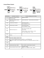
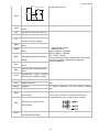
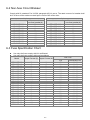
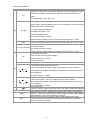
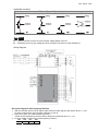
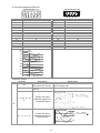
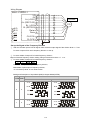
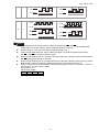
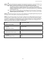
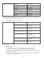
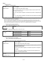
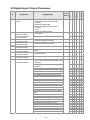
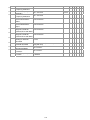
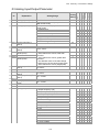
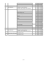
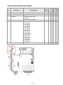
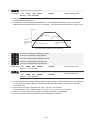
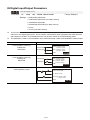
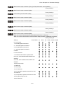
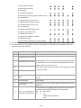
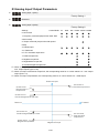
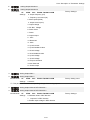
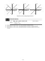
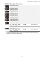
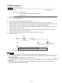
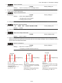
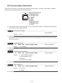
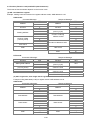
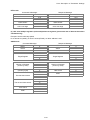
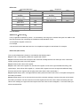
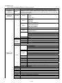
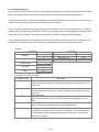
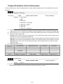
10 Speed Feedback Control Parameters In this parameter group, ASR is the abbreviation for Adjust Speed Regulator and PG is the abbreviation for Pulse Generator. Selection of Encoder Control Mode VFPG Settings FOCPG TQCPG FOCPM Factory Setting:0 0: No function 1: ABZ 2: ABZ+Hall 3: SIN/COS + Sinusoidal 4: SIN/COS + Endat 5: SIN/COS 6: SIN/COS + Hiperface When Pr.10-00 is set to 3, encoder will have one sine and one cosine signal for each revolution. The signal must be: 0.75 to 1.2Vpp for the amplitude with phase angle 90°±5 elec. (EX: ERN 1185 ERN 1387) When setting is 4 or 6, it needs to wait for 2 seconds after applying the power to execute RUN command. Detection of the magnetic pole: Setting 1 or 5: The AC motor drive will output short circuit to detect the position of the magnetic pole. At this moment, the motor will generate a little noise. Setting 2: The AC motor drive will detect the position of the magnetic pole by the UVW signal of encoder. Setting 3: The AC motor drive will detect the position of the magnetic pole by the sine signal of encoder. Setting 4 or 6: The AC motor drive will detect the position of the magnetic pole by the communication signal of encoder. Reference table for tuning Setting of PG PG signal type Applicable PG card Pr.08-00=1 Pr.08-00=3 signal type 10-00=1 A, B, Z EMVL-PGABO/ABL Motor will run Motor will run 10-00=2 A, B, Z+U, V, W EMVL-PGABL Motor will run Motor will run SIN/COS+ 10-00=3 EMVL-PGH01/02 Motor will run Motor will run Sinusoidal 10-00=4 SIN/COS+Endat EMVL-PGS01 Motor will run Motor won’t run 10-00=5 SIN/COS EMVL-PGH01/02 Motor will run Motor will run 10-00=6 SIN/COS + Hiperface EMVL-PGS01 Motor will run Motor won’t run Encoder Pulse Control Mode VFPG Settings FOCPG TQCPG FOCPM Factory Setting:600 1~25000 A Pulse Generator (PG) or encoder is used as a sensor that provides a feedback signal of the motor speed. This parameter defines the number of pulses for each cycle of the PG control. 12-74