1
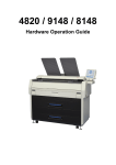
housEvolve
Telephone Interface Module
User Manual and Installation Guide
FREEVOLVE® LLC
Copyright 2008
Introduction
Thank you for purchasing a FREEVOLVE® product. We designed it to
provide you with years of reliable service.
The following setup instructions will help you get up and running quickly,
and while we hope all our products are self-explanatory, the enclosed user
guide should cover all questions you may have. Please refer to the “Support”
section of our website – www.freevolve.com – for additional information.
Warranty Information
All FREEVOLVE® products are covered against manufacturing defects for
a period of 2 years from the date of purchase. During the warranty period we
will replace any defective unit free of charge.
The warranty does not cover any problem caused by accident; abuse;
neglect; improper installation, operation or modification; any misuse
contrary to the instructions in the user guide.
2
FREEVOLVE® LLC
Copyright 2008
Installation and Configuration
The Telephone Interface Module is supplied with a Class 2 AC/DC adapter
and a 7ft telephone cord.
3
FREEVOLVE® LLC
Copyright 2008
1. Installation
• Place the Telephone Interface Module at its desired location.
While this unit will work in any position, we recommend a flat
surface in a conveniently accessible area.
• Connect the included phone cord between the Telephone
Interface Module’s “IN” jack and a telephone wall outlet.
• If you use a Telephone Answering Machine in your home, we
strongly recommend that you connect its phone cord to the
“OUT” jack of the Telephone Interface Module. While not
mandatory, this setup will allow both devices to operate
seamlessly with each other.
• Insert the enclosed AC/DC adapter into a wall outlet, and then
connect its output plug to the DC IN jack on the Telephone
Interface Module.
4
FREEVOLVE® LLC
Copyright 2008
If you purchased the Telephone Interface Module as a stand-alone device
(that is, without any peripheral modules), your installation is complete.
Please proceed to the Configuration section.
2. Building a housEvolve system
The housEvolve system grows around the Telephone Interface
Module, which is the central element of the housEvolve network. It is
also the contact point between the remote user and all available
monitoring and control functions.
The housEvolve network is flexible, allowing for a wiring
configuration most appropriate for your needs. Peripheral components
may be directly connected to the “System Components” jacks on the
Telephone Interface Module, or they may be daisy-chained – as long
as each network “chain” includes a connection to the Telephone
Interface Module.
Building a housEvolve system is as simple as connecting the
peripheral modules to the Telephone Interface. The only requirement
is that during the initial system installation the Telephone
Interface Module must be ON and each peripheral module must
connect to the Telephone Interface one at a time. Once a
peripheral module is added to the network, please allow 30
seconds for the Telephone Interface to identify, configure and
incorporate the capabilities of the new device into the system.
Then a new peripheral module may be added. Note that this
requirement is only applicable to the initial installation of a peripheral
module. If, for example, you need to move the Telephone Interface to
a new location at a later time, there are no restrictions on the
connection order.
• First, install and connect each peripheral module to the
appliance under its control according to the instructions
provided (ex: install and connect the Thermostat Module to the
HVAC system before connecting it to the Telephone Interface).
• Ensure that the Telephone Interface Module is powered (the
LCD display is ON).
• Using the network cable provided, connect each peripheral
module, one at a time, either directly to a “System
Components” port on the Telephone Interface Module or daisy-
5
FREEVOLVE® LLC
Copyright 2008
chained off another peripheral module already connected to the
Telephone Interface. As each new peripheral module is
recognized and configured, the Telephone Interface display will
be updated to reflect the current size of your housEvolve
system.
6
FREEVOLVE® LLC
Copyright 2008
3. Configuration
Now that the Telephone Interface Module is installed, there are a few
configuration tasks that need to be performed in order for you to be
able to take full advantage of its capabilities. Before we get to that,
however, it is time for a few words on how to interact with it.
All features offered by the Telephone Interface Module features are
accessed and most can also be altered through the use of the 5-button
navigation keypad shown below, in conjunction with the display. The
only exceptions are those features requiring a numeric input (ex:
passwords or telephone numbers), for which the numeric keypad is
used. Most of the information displayed on any screen is selectable
and configurable. You simply navigate to the feature of interest and
then act upon it.
General guidelines: the Left-Right keys (< >) are used to drag the
selection markers to the feature of interest, while the UP-Down keys
(^ v) are used to roll up/down through the available settings for the
selected feature. The Select key (•) is used to confirm the feature
chosen or to act upon a navigation selection (Ex: sending the display
to the “Settings” screen).
The Telephone Interface Module enters a “stand-by” mode in the
absence of user action, identified by the main screen displayed in a
low backlight setting (the screen is dimly lit) and without any
selection markers. Any button press in this mode causes the system to
enter the “user” mode, defined the screen switching to a bright
backlight setting and the selection markers appearing around the
default main screen feature.
As an example we will go through setting the clock on the main
screen. The default value at startup is Wed, 12:00A. Since the clock
7
FREEVOLVE® LLC
Copyright 2008
begins running as soon as the system is powered, the time on your
screen may be different by now.
a. With the system in stand-by mode, press any key. The screen will
light up and the default feature is selected, as shown below.
b. Use the Left or Right keys to move the selection markers until they
surround the clock “day” feature.
c. Use the Up or Down button to scroll through the days of the week
until reaching the desired day.
d. Press the Right button to select the clock “hour” feature.
e. Use the Up or Down button to increment/decrement the hour field.
Note: keeping the Up/Down key pressed will allow the system to
scroll through the hour field.
f. Press the Select button to toggle between 12/24 clock display
mode. Note that in 24hr mode the AM/PM marker at the end of the
time field disappears.
8
FREEVOLVE® LLC
Copyright 2008
g. Press the Right button to select the clock “minute” feature.
h. Use the Up or Down button to increment/decrement the minute
field. Note: keeping the Up/Down key pressed will allow the
system to scroll through the minute field.
i. That’s it! The Telephone Interface Module will return to “standby” mode after a few seconds of user inactivity, keeping the newly
chosen time.
9
FREEVOLVE® LLC
Copyright 2008
Now that interacting with Telephone Interface Module is, hopefully, no
longer a mystery, let’s finish the configuration process.
First, you need to set up an access password in order to be able to
communicate with the Telephone Interface Module over the phone, and to
alter certain protected settings.
Enter User mode by pressing any key. The main screen looks like this:
Press Select (•) to edit the access password. The screen changes:
Use the number pad to enter the desired password. The screen will
follow your entries:
When finished, press Select. The password will be masked from now
on:
You can always delete it or enter a new one.
10
FREEVOLVE® LLC
Copyright 2008
NOTE: if you delete this password (or don’t enter one) you will not be
able to interact with the Telephone Interface Module if you initiate the
call.
The second configuration step necessary to get the Telephone Interface
Module working properly is setting up at least one access phone number. An
access number is a telephone number the Telephone Interface Module dials
when it has something to report. You can configure up to 5 phone numbers,
and when a problem arises they will be called, in order, at intervals of 25
seconds, until you acknowledge receipt of the report. If the Telephone
Interface Module does not receive a confirmation after going through all the
numbers in the list, it waits about 25 minutes and starts the whole process
again.
You can edit your access numbers directly from the screen above or,
if the device has already timed out and moved back to the main
screen, start again from there:
Press Select to edit the access numbers. This feature is password
protected, so you will need to enter the password you just created on
the next screen. Once that is done, the display goes to the first access
number screen:
Use the number pad to enter a phone number – just as you would have
to dial it from this location – into the selected slot. To choose a
different slot, simply use the Left or Right button to navigate to it.
11
FREEVOLVE® LLC
Copyright 2008
Once your target slot is selected, simply start typing the number using
the numeric keypad:
When finished, press Select. The number moves to the right of the
screen and the selection markers move to the next slot.
To enter another number, simply repeat the process:
To enter more than 3 access numbers, choose “MORE” and press
select. The remaining number slots become visible. When finished,
choose “DONE” and press Select. You device returns to the main
screen and there are no more messages displayed in the lower left
corner.
Finally, if your home uses an Answering Machine, the Telephone Interface
will need to be told the number of rings to which the Answering Machine is
configured. The Telephone Interface Module is now ready for use.
12