1
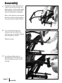
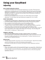
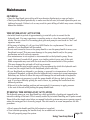
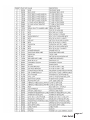
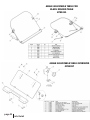
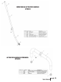
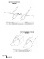
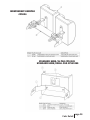
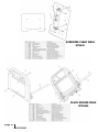
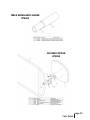
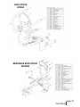
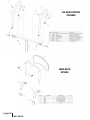
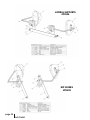
™
5000
Owner’s Manual
Table of Contents
Introduction. . . . . . . . . . . . . . . . . . . . . . . . . . . . . . . . . . . . . . . 1
Safety Precautions . . . . . . . . . . . . . . . . . . . . . . . . . . . . . . . . 2
Assembly . . . . . . . . . . . . . . . . . . . . . . . . . . . . . . . . . . . . . . .3-14
Using Your EasyStand . . . . . . . . . . . . . . . . . . . . . . . . 15-18
Parts & Options. . . . . . . . . . . . . . . . . . . . . . . . . . . . . . . . 19-36
Standing Log . . . . . . . . . . . . . . . . . . . . . . . . . . . . . . . . . . . . . 37
Specifications . . . . . . . . . . . . . . . . . . . . . . . . . . . . . . . . . . . . 38
Limited Warranty . . . . . . . . . . . . . . . . . . . . . . . . . . . . . . . . 39
Introduction
Congratulations on your purchase of the EASYSTAND 5000 standing frame! We at Altimate
Medical, Inc. have designed the EasyStand 5000 with your comfort and happiness in mind.
This manual is an integral part of your standing system and should be read completely and
thoroughly by anyone that will be operating the unit.
This will ensure that the EasyStand 5000 is assembled properly and then used in the most
beneficial manner.
AMI recommends that an attendant be present when the EasyStand 5000 is being used.
Should any problem arise that you cannot solve by reading this manual, please contact your local
dealer or call Altimate Medical, Inc. at 1-800-342-8968 or 507-697-6393.
It is important and necessary that you inspect your EasyStand 5000 periodically to assure that it is
in safe operating condition. Minor adjustments can be made by the operator. However, replacement of worn parts, major adjustments, or any other important corrections should be handled by
an authorized dealer or service center. Only Altimate Medical, Inc. approved replacement parts
should be used to ensure safety and performance.
The EasyStand 5000 should not be used by any individual with paralysis of either the upper
and/or lower body that has been confined to a bed or wheelchair for an extended period of time
without first consulting a qualified physician.
Failure to consult a qualified physician prior to using the EasyStand 5000 could lead to severe
medical problems. We recommend that a good standing program be established and supervised
by a qualified registered physical therapist.
Date Purchased
page 1
Introduction
Serial #
Safety Precautions
• The EasyStand 5000 is designed to accommodate most individuals from 5’- 6'5" (152cm-195cm) and up
to 280 lbs (127kg). If you do not meet these specifications and have not been properly fit by a qualified
therapist or physician, Altimate Medical Inc. does not recommend that you use the EasyStand 5000.
• Altimate Medical Inc. recommends that you consult with your therapist or physician prior to starting a
standing program.
• Check your EasyStand periodically to make sure that all nuts, bolts and adjustable parts are tightened
securely.
• Never reposition the foot holders while you are in the standing position. Consult with your therapist or
physician for proper foot placement and angle.
• If the unit was exposed to temperatures of less than 50˚F (23.5˚C), you must allow the unit to warm up to
room temperature before use.
• Use body weight to lower the seat. Do not use excessive force.
• The EasyStand is for indoor use only.
• Violently thrusting backwards in the EasyStand may cause it to tip.
• If you ordered casters or the mobile option, you should always put the casters and/or wheels in the locked
position before transferring into the EasyStand. Use these locks whenever you want to keep the EasyStand
stationary.
• Do not use the mobile option on ramps or uneven surfaces.
Safety Precautions
page 2
Assembly
1
Depending on what base style you
ordered you will have either level
glides, casters, or the mobile option.
Turn the base over as shown and
locate the enclosed tool package.
Many of the pictures in this manual
show the optional ratchet handles.
You may have the standard knobs.
2
If you ordered the high back
extension and level glides, the
anti-tips must be installed with the
rear level glides as shown.
Tighten securely.
3
Turn the level glides into the
threaded holes in the back of the
base and tighten securely. Insert
end caps
page 3
Assembly
4
5
The front level glides
(with adapters) must be
tightened securely onto the frame
as shown.
If you ordered the high back
extension, the anti-tips must be
installed with the rear casters as
shown.
Tighten securely.
6
Thread the casters into the rear of
the base and tighten
securely.
Caution: The casters must be
threaded all the way in.
Assembly
page 4
7
8
The front casters must be attached
securely into the frame as shown.
Thread the caster completely into the
adapter with the enclosed wrench.
If you ordered the mobile option,
install the two casters into the back
of the unit (as in figure #5 or 6,
page 4) then install the drive wheels
into the front.
Tighten securely.
If you ordered the Mobile Option
refer to the assembly instructions
you received.
9
If you ordered the optional table
swing-away sleeve mount it before
installing the table frame. It can be
mounted on the right or left side.
Put the quick pin back into the
other side. Only one quick pin will
be used if you have the table
swing-away sleeve option.
page 5
Assembly
10
11
12
With your unit in the upright
position, remove the quick pins.
Place H-frame into base with
kneepad bracket facing inward.
Replace quick pins.
Be sure that H-frame bracket
is facing inward.
Standard Knee bracket
Attach the kneepad and
tighten securely.
Caution: Keep kneepad in the
lower position when not in use.
If you ordered the independent
adjustable kneepad, slide the notch
onto the pegs of the lower table
H-frame.
Note: Table H-frame must be
installed properly for kneepad to
function.
Caution: Keep kneepad in the
lower position when not in use.
Assembly
page 6
13
14
To install the table, loosen the
H-frame knobs slightly and be sure
the front pad bracket faces toward
the seat.
Insert the table into the H-frame
and push the spring button to
continue installation. Tighten the
knobs or the optional ratchet
handles.
Note: Spring button indicates the
highest allowable table adjustment.
There is only one spring button.
15
Attach the front pad and tighten
securely.
page 7
Assembly
ratchet handles or
knobs
16
17
The actuator handle can be installed
on the right or left side.
Attach the actuator handle so that
the handle is near vertical. Use the
enclosed allen wrench and a
multi-use wrench.
Tighten Securely.
18
If you ordered the removable
actuator handle it can be removed
by loosening the knob as shown.
Assembly
page 8
19
To install the back option, loosen
the quick adjust knob on the square
tube. Press the spring button on the
lower following arm and insert it
into the round corresponding tube.
Continue pressure until you hear
the spring button "click".
20 Slide the upper square back tube
into the corresponding seat
adjustment tube.
Depress the spring button to insert
and continue until you here a“click”.
21
Be sure that the colors on the
following arm and the seat
adjustment tube are the same. If
the colors are not the same, damage
will occur to the unit when raised to
the standing position.
Tighten the quick adjust knob
securely.
page 9
Assembly
22 To install the seat, first raise the
seat by pumping the actuator
handle.
hip guides must be
23 Optional
installed with the seat. To make it
easier to assemble, temporarily bolt
the seat on one side only. Do not
tighten at this time.
bolts for the seat are found in
24 The
the seat.
Remove bolts and place the seat
onto the frame with the narrow end
toward the rear of the unit.
Tighten securely.
Assembly
page 10
25
26
27
Attach hip guide into remaining
holes then remove temporary bolts
and attach final hip guide.
Lower the seat by applying weight
and pulling back gently on the
actuator handle.
Attach the back and tighten securely
with the enclosed allen wrench.
page 11
Assembly
28 If you ordered the high back
extension, slide it into the back
frame before installing the lower
back. Now install the lower back
pad with the attached bolts.
Tighten Securely.
adjust the footrests, loosen the
29 To
quick adjust handles and pivot the
footrests forward, then tighten
securely.
30 For installation of the laterals you
must either widen or remove the
pad brackets for ease in installation.
Note: The quick adjust knobs go to
the top (see fig. #31).
Assembly
page 12
31
If you have the high back extension
with laterals, install the high back
onto the unit, then attach lower
backpad and laterals as shown.
Tighten securely.
Caution: Lateral rod must extend
through clamp as shown.
universal headrest receiver can
32 The
be used with a variety of other
manufacturers’ headrests. Headrest
receiver will snap down into
maximum height position. Depress
again to lower headrest.
Tighten quick adjust knob.
33 If you are using it with the Whitmyer
Pro receiver, Pro-MS, Pro-MD or the
soft/plush series receiver #M1012, use
the four bolts supplied by Whitmyer to
attach your headrest.
page 13
Assembly
34 For use with the Stealth
, Otto
Bock™ or Whitmyer #M0012
detachable mount, you must remove
the auxiliary mounting plate.
®
35 If you are using the Whitmyer
detachable mount ( fig. A ), remove
the chrome insert and knob, then
insert it into the universal
headrest receiver as shown and
secure with knob.
Note: If you do not have a knob
supplied by Whitmyer, use the
included buttonhead bolt.
(fig. A)
you are using the Otto Bock™ or
36 If
Stealth headrest, use the two of the
®
provided buttonhead bolts to fasten
their hardware as shown.
Assembly
page 14
Using your EasyStand
Adjusting
SEAT DEPTH/BACK ANGLE
•
•
To adjust the seat depth, first loosen the quick adjust knob on seat tube. Then depress the
spring button and position the seat to the desired depth. Tighten the knob securely when desired
adjustment is accomplished. You have seven seat depth options ranging from 18 to 24 inches. When
adjusting the seat depth, it is important to have your knee as close to the seat pivot as possible for
proper lift to the standing position.
Position the back adjustment tube in the same color-coded setting as the seat depth
adjustment. You have fifteen back depth adjustments ranging from 16 to 22 inches.
FOOT HOLDERS
•
•
•
•
•
•
Consult with your therapist or physician for proper foot placement and angle.
Foot holders should be raised/lowered so that the knee is as close to the seat pivot as possible.
Never reposition the foot holders while you are in the standing position.
The foot holders can be independently adjusted in swivel, height, and pivot.
To adjust the swivel or pivot of the foot holders, loosen the quick adjust handles on each foot
holder clamp. When you find the desired foot position, tighten the handles securely.
To adjust the height loosen the same quick adjust handle of the foot holder clamp. Loosen the
factory adjusted bolt on the outside of each clamp only if necessary. Now the clamps will
slide up with 9” of adjustment. Tighten securely.
MOBILE OPTION
•
•
Do not use the mobile option on ramps, uneven surfaces or outdoors.
Before transferring into the EasyStand with the Mobile Option, make sure that the casters and
the push rim locking mechanisms are in the locked position. Use these locks when ever you
want to keep the EasyStand stationary.
KNEE PAD
•
The knee support should be snug when you are in the seated position. Adjust the foot holders
so that the user’s knees are as close to the seat pivot point as possible.
(If necessary, the knee pad can be inverted on the frame for further adjustment variations)
FRONT PAD
•
When in the standing position, the front pad should support your upper body. Adjust the tray
height and depth so you feel comfortable. The front pad can also be independently adjusted
for proper height and it can be inverted as the adjustment holes are offset allowing further
adjustment variations.
page 15
Using Your EasyStand
Transferring
• For proper transfer techniques, please seek professional advice from your
therapist or physician before transferring.
• Always lock the wheel locks on your wheelchair and all four casters on the EasyStand before
transferring.
• If you do not need assistance in transferring, position your wheelchair next to the EasyStand
and remove the side support. Make sure that the knee support is flipped up to allow you to
position your feet. Complete your transfer and position your feet in the footplates. Secure the
foot straps and reposition the knee and side supports.
• If required, many patient lifts can be used for transfers. Remove the front table assembly of the
EasyStand and transfer in from the front or use the removable back option and transfer from
the rear.
• To transfer with a sliding board, position your chair parallel to the EasyStand, remove the
side support and flip the knee support back. Be sure that your wheel locks are locked. The front
end of the EasyStand can be removed so an assistant can use proper body mechanics for a standing
pivot or fully assisted sliding board transfer.
• When transferring out of the EasyStand, pump the seat up so that it is equal to or higher
than the seat you are transferring back in to.
3.
1.
2.
4.
Using Your EasyStand
page 16
Standing
• Please consult with your therapist or physician before starting a standing
program.
• Once transferred into the EasyStand, position your feet and the knee support and secure any
straps. Push the pump handle forward with 15-25 strokes. The seat will slowly rise into the
standing position. Remember that you can stop the seat anywhere between the sitting and
er
standing position.
low
ais
e
• To return to the seated position, move and hold the pump handle
toward the rear until you have reached your desired position. The seat
will slowly lower until you release the handle.
r
• If you have difficulty getting the seat to lower, you may not be applying
the proper pressure to the handle.
• If you have difficulty reaching the handle, you may consider
purchasing the actuator handle extension.
• If you have difficulty getting the seat to lower, check to see that you have the seat tube and
the back adjustment tube set at the same color-coded setting. Failure to do this may cause
serious damage to your unit!
• If the unit is in the standing position and nobody is in it, apply moderate pressure to the seat
of the unit while holding the pump handle back. Do not use excessive force.
page 17
Using Your EasyStand
Maintenance
GENERAL
• Clean the EasyStand 5000 with a mild non-abrasive disinfectant or soap and water.
• Check your EasyStand periodically to make sure that all nuts, bolts and adjustable parts are
tightened securely. Failure to do so may result in parts falling off which may cause a choking
hazard for children
THE HYDRAULIC ACTUATOR
• An initial break-in period of approximately 50-100 full cycles is normal for the
hydraulic unit. You may experience a squealing noise or a less-than-smooth forward
stroke. The very close fit of its mating parts give each pump its own break-in “feel” and
signature noise.
• If the pump is leaking oil, call your local AMI Dealer for a replacement. The serial
number of your EasyStand will be needed.
• Do not exert excessive force on the pump handle or use the pump handle to move your
EasyStand around. This may cause damage to the pump handle and/or the pump
mechanism and will void any warranty.
• User maintenance is not required or recommended on the hydraulic pump. Never
apply lubricant, household oil, grease, or a similar product to any part of the unit.
Some compounds may react with the seals used in the manufacture of this product.
This may damage the unit and will void any warranty.
• Do not exceed the rated weight capacity of the equipment for which this hydraulic unit
is used on (the weight limit for the EasyStand 5000 is 280 lbs).
• If your EasyStand was shipped to you during or exposed to a temperature of less then
50 degrees Fahrenheit, you must allow the hydraulic unit to warm up to room temperature
before any use. Failure to follow this step could damage the unit and render it inoperable.
• It is sometimes not necessary to push the pump handle all the way back to lower the
seat. If you have difficulty getting the seat to lower, try pushing the handle back into
different positions.
• If the unit is in the standing position and unoccupied, it is necessary to apply pressure
to the seat of the unit while pushing the pump handle back.
PURGING THE HYDRAULIC ACTUATOR
The hydraulic pump on your EasyStand has a high probability of getting air trapped in the
internal workings of the unit. This is usually caused by in-transit handling and is quite normal.
Please follow the simple steps below, as manual hydraulic systems may never operate properly
unless the entrapped air is correctly purged. The unit must be at room temperature for this
procedure.
1. Slowly pump the handle until the full extension is reached.
2. Now continue pumping the handle slowly for an additional 10 strokes.
This will properly purge the system.
Using Your EasyStand
page 18
®
EasyStand Parts Detail
5000 OPTION OVERVIEW
page 19
Parts Detail
Parts Detail
page 20
5000 BASIC FRAME
page 21
Parts Detail
Parts Detail
page 22
ANGLE ADJUSTABLE TABLE FOR
BLACK MOLDED TABLE
#P81011
ANGLE ADJUSTABLE TABLE OVERSIZED
#P80997
page 23
Parts Detail
LEVEL GLIDES
#P10126
LOCKING CASTERS
#P5062
Parts Detail
page 24
MOBILE OPTION
#P5200
ACTUATOR HANDLE
#P58483
page 25
Parts Detail
REMOVABLE ACTUATOR HANDLE
#P5020
ACTUATOR HANDLE EXTENSION
#P5022
Parts Detail
page 26
SECURE FOOT OPTION
#P80616
FOOT HOLDERS W/STRAPS
#P80634
page 27
Parts Detail
INDEPENDENT KNEEPAD
#P5026
STANDARD KNEE/XL PAD #P10128
STANDARD KNEE/SMALL PAD #P10128S
Parts Detail
page 28
OVERSIZED CLEAR TABLE
#P5040
BLACK MOLDED TABLE
#P10600
page 29
Parts Detail
TABLE SWING-AWAY SLEEVE
#P5024
NO-TABLE OPTION
#P5250
Parts Detail
page 30
ARM TROUGHS
#P5030
ROHO® SEAT SET #81019
page 31
Parts Detail
BACK OPTION
#P5100
REMOVABLE BACK OPTION
#P5100R
Parts Detail
page 32
NO BACK OPTION
#P58582
HIGH BACK
#P5150
page 33
Parts Detail
HEAD SUPPORT
#P5032
UNIVERSAL HEAD SUPPORT RECEIVER
W/HIGH BACK
#P80643
Parts Detail
page 34
LATERAL SUPPORTS
#P5036
HIP GUIDES
#P5038
page 35
Parts Detail
LARGE CHEST STRAP
#P51600
POSITIONING BELT
#P51500
LARGE CHEST VEST
#P80633
MEDIUM CHEST VEST
#P80632
Parts Detail
page 36
page 37
User Log
EasyStand 5000 Specifications
Height Range
Weight Limit
Seat Depth Range
(from front of seat)
Seat Height from Floor
(transfer height)
Seat to Footplate Range
Table/Frontpad Depth Range
(when standing)
Table Height Range
(from knee pivot)
Basic Kneepad Depth Range
Knee Width Large
(center to center)
Footprint
Weight of Basic Unit
Frame Color
Standard Upholstery Color
Black Molded Table Size
5’0”-6’5”
280 lbs.
18”-24”
152-195cm
127kg
46-61cm
19.5”
49cm
11”-19”
2”-10”
28-48cm
5-25cm
25.5”-35”
65-89cm
3”-5”
9”
8-13cm
23cm
26.5”x33”
67x84cm
118 lbs.
54kg
Black Powder Coat
Graphite Gray
19.5”x20”
49x51cm
Specifications
page 38
Limited Warranty
This warranty is extended only to the original purchaser/customer (or dealer non consumer who does not buy or
resell). Altimate Medical, Inc. (AMI) warrants the EasyStand 5000 against defects in materials and workmanship
as listed below.
• Steel Frames - 5 year warranty
• Hydraulic Actuator - 2 year warranty
• Upholstered components, plastic pads, rubber parts, painted surfaces, bearings and other parts not specifically identified
above - 90 day warranty
The warranty period commences for the consumer on the purchase date from the seller/dealer. If the product is
rented or otherwise not sold to a consumer, the warranty period commences from the date of invoice from AMI.
Any product proven to AMI satisfaction to be defective and within warranty period, shall be repaired or replaced
at AMI’s option.
AMI’S SOLE OBLIGATION AND YOUR EXCLUSIVE REMEDY UNDER THIS WARRANTY SHALL BE
LIMITED TO SUCH REPAIR AND/OR REPLACEMENT. This warranty does not include any labor charges
incurred in replacement parts installation. Freight charges to factory are at the expense of consumer to seller.
Return freight charges will be prepaid by AMI. For warranty service, please contact the authorized dealer from
whom you purchased your AMI product. In the event you do not receive satisfactory warranty service, please write
directly to AMI at the address below. Do not return products to our factory without prior authorization.
LIMITATIONS AND EXCLUSIONS: The foregoing warranty shall not apply to serial numbered products if the
serial number has been removed or defaced. Products subject to negligence, abuse, misuse, improper operation,
improper maintenance, improper storage, or damages beyond AMl’s control are not covered by this warranty, and
that evaluation will be solely determined by AMI. The warranty shall not apply to problems arising from normal
wear or failure to follow instructions. The warranty will be void if parts not manufactured by AMI or parts
not complying with original equipment specifications are added to an AMI product.
THE FOREGOING WARRANTY IS EXCLUSIVE AND IN LIEU OF ALL OTHER EXPRESS WARRANTIES. AMI
SHALL NOT BE LIABLE FOR ANY CONSEQUENTIAL OR INCIDENTAL DAMAGES WHATSOEVER.
AMI maintains a policy of continual product improvement and reserves the right to change features, specifications,
and prices without prior notification. Check with AMI for latest information.
Altimate Medical, Inc., P.O. Box 180, 262 W. 1st St., Morton, MN 56270 USA
Phone: 507•697•6393 Fax: 507•697•6900 1 800•342•8968
www.easystand.com [email protected]
Revised March 2007
Environmental Issues
After life of the product:
• Recycle in accordance with the recycling codes of your country.
• Recycle all metal parts.
• Plastic parts should be disposed of or recycled according to the directive in your country.
• Please inquire at your local disposal management and recycling center for local codes.
• Return hydraulic actuator to Altimate Medical, Inc.
page 39
Warranty
P.O. Box 180
262 West 1st St
Morton, MN 56270
Toll Free: 800.342.8968 or 507.697.6393
Fax Free: 877.342.8968 or 507.697.6900
email: [email protected]
www.easystand.com
™
Standing technology should only be used under the guidance of a physician with recommendations for standing program protocol and any
medical precautions. Standing programs should be monitored by the attending therapist. AMI maintains a policy of continual product
improvement and reserves the right to change features, specifications, and prices without prior notification. Check with AMI for latest info.
FORM MAN5000 0307 Copyright © 2007 Altimate Medical, Inc. All rights reserved. Printed in the U.S.A.