1
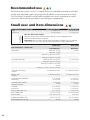
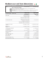
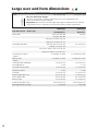
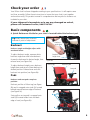
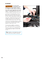
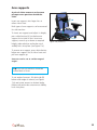
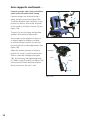
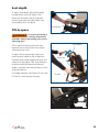
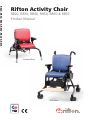
R820, R830, R840, R850, R860 & R870
Rifton Activity Chair
R820, R830, R840, R850, R860 & R870
Product Manual
Standard Base
Hi/lo Base
®
Contents
Important information
4
Safety messages
5
Recommended use
6
User and item dimensions
Check your order
6-8
9
Basic components
Backrest and pads
Seatbelt
Arm supports
9
10
11-12
Seat depth
13
Tilt-in-space
13
Spring options
14-16
Seat quick-connect
17-18
Standard base
Adjustable legs
19
Seat height
19
Footboard
19
Hi/lo base
2
Seat height
20
Caster brakes and swivel lock
21
Footboard
22
© 2014 Rifton Equipment
Contents continued. . .
Accessories
Headrests
23
Whitmyer adapter plate
24
Lateral supports
25
Chest strap
26
Butterfly harnesses
27
Thigh belt
28
Pelvic harness
29
Hip guides
30
Abductor
31
Adductors
31
Leg prompts and ankle straps
32
Sandals and wedges
33
Lumbar and seat support kit
34
Backrest filler pad
34
Tray
35
Handhold
35
Push handles
36
Footboard lift
36
Mini kit
37
Maintenance, cleaning and warranty
38
Materials and user modifications
39
3
IMPORTANT
Please save this product manual for future reference. Additional copies are
available at www.rifton.com
Key for users
Use this key to determine which sections of this product manual apply to you.
Technical Users For professionals who order and set up Rifton products.
Home Users For care-givers who use Rifton products on a regular basis.
Maintenance Personnel For anyone who is responsible for service or
re-ordering of Rifton products and parts.
4
WARNING
• Thoroughly read and understand the information in this product manual before
attempting to use this product. If the procedures and instructions in this product manual
are not followed, serious injury or death could occur.
• A qualified professional must assess the appropriateness and safety of all equipment for
each user.
• This product is intended for use by clients of unreliable judgment. Adult supervision is
required at all times.
• To prevent falls and injuries:
○ Do not use this product on rough and uneven terrain, around swimming pools, or
near stairways.
○ Ensure the appropriate use of straps and supports at all times. Straps and supports
are provided for the safety of the user and must be carefully adjusted for comfort and
security.
○ Tighten all adjustment knobs before use and immediately after making any
adjustments.
• To prevent pinching or crushing:
○ Keep clients away from under the seat of the chair.
○ Keep hands above the seat when the spring option is in use.
• To prevent falls, strangulation, head entrapment or other injuries, always use seatbelt
or pelvic harness when the tray, chest straps, thigh belt, mini trunk support, or butterfly
harness are in use.
• Do not use this product for clients outside the height and weight limits specified in this
manual.
• To prevent structural failure, which may result in serious injury or death:
○ Inspect this product and accessories regularly for loose or missing screws, metal
fatigue, cracks, broken welds, missing attachments, general instability or other signs
of excessive wear.
○ Immediately remove this product from use when any condition develops that might
make operation unsafe.
○ Do not use Rifton components or products for any purpose other than their intended
use.
5
Recommended use
The Rifton Activity Chair is a Class 1 medical device. It is intended to provide comfortable
seating with adjustable support for people with disabilities in the classroom or at home.
The chair allows for growth, can be used by multiple users and is available with various
accessories that are easily removable as the client gains independence.
Small user and item dimensions
User dimensions – inches (cm)
Height
with mini kit
R820 Standard base
32–48 (81-122)
28–38 (71-97)
R830 Hi/lo base
32–48 (81-122)
28–38 (71-97)
Key user dimension: height
The user’s overall height is a general guide to help you select the appropriate chair.
Choose the model that allows for growth.
Important: Make sure that seat width, depth and height are adequate for each individual
user, and that the user’s weight does not exceed the maximum weight recommended.
Item dimensions – inches (cm)
Frame width
R820 small
R830 small
Standard base
Hi/lo base
short legs: 21 (53)
25 (63)
long legs: 23 (58)
short legs w/ wheels: 22½ (57)
long legs w/ wheels: 23½ (60)
Seat height above floor
short legs: 9½–12½ (24-32)
10–25 (25-64)
long legs: 18½–21½ (47-55)
short legs w/ wheels: 13½–16½
(34-42)
long legs w/ wheels: 18½–21½ (47-55)
Seat angle (tilt-in-space)
- degrees
Backrest angle
- degrees
Seat height above footboard
with mini kit
Seat width with hip guides
(without hip guides)
Seat depth
with mini kit
Armrest height above seat
Trunk support width
Backrest height
Headrest height above seat
Max. working load – lbs. (kg)
6
15° forward, 15° back
15° forward, 25° back
5° forward, 20° back
5° forward, 20° back
9–12 (23-30)
6–9 (15-23)
9 –12 (23–30)
6–9 (15–23)
7–9 (18-23)
12 (30)
7–9 (18–23)
12 (30)
8–12 (20-30)
7–11 (18-28)
8–12 (20–30)
7–11 (18–28)
5–7½ (13-19)
5–7½ (13–19)
5½–11½ (14-29)
5½ –11½ (14–29)
12½–15½ (32-39)
12½–15½
14½–21 (37–53)
14½–21 (37–53)
75 (34)
75 (34)
Medium user and item dimensions
User dimensions – inches (cm)
Height
R840 Standard base
40–56 (102–142)
R850 Hi/lo base
40–56 (102–142)
Key user dimension: height
The user’s overall height is a general guide to help you select the appropriate chair.
Choose the model that allows for growth.
Important: Make sure that seat width, depth and height are adequate for each individual
user, and that the user’s weight does not exceed the maximum weight recommended.
Item dimensions – inches (cm)
Frame width
R840 medium
R850 medium
Standard base
Hi/lo base
short legs: 23¼ (59)
27½ (70)
long legs: 24½ (62)
short legs w/ wheels: 24½ (62)
long legs w/ wheels: 25½ (65)
Seat height above floor
short legs:12½–16½ (32–42)
12–23 (30–58)
long legs: 19–23 (48–58)
short legs w/ wheels: 16–20 (41–51)
long legs w/ wheels: 19–23 (48–58)
Seat angle (tilt-in-space)
- degrees
Backrest angle
- degrees
Seat height above footboard
with footboard lift
Seat width with hip guides
(without hip guides)
15° forward, 15° back
15° forward, 25° back
5° forward, 20° back
5° forward, 20° back
12–16½ (30–41)
12–16½ (30–41)
8–12½
8–12½
8½–11½ (22–29)
8½–11½ (22–29)
14 (36)
14 (36)
Seat depth
11–16 (28–41)
11–16 (28–41)
Armrest height above seat
7–10½ (18–27)
7–10½ (18–27)
Trunk support width
6½–12 (17–30)
6½–12 (17–30)
15½–19 (39–48)
15½–19 (39–48)
17½–24½ (44–62)
17½–24½ (44–62)
150 (68)
150 (68)
Backrest height
Headrest height above seat
Max. working load – lbs. (kg)
7
Large user and item dimensions
User dimensions – inches (cm)
Height
R860 Standard base
50–74 (127–188)
R870 Hi/lo base
50–74 (127–188)
Key user dimension: height
The user’s overall height is a general guide to help you select the appropriate chair.
Choose the model that allows for growth.
Important: Make sure that seat width, depth and height are adequate for each individual
user, and that the user’s weight does not exceed the maximum weight recommended.
Item dimensions – inches (cm)
Frame width
R860 large
R870 large
Standard base
Hi/lo base
short legs: 26¼ (66)
29¾ (75)
long legs: 26¼ (66)
short legs w/ wheels: 27¾ (71)
long legs w/ wheels: 27¾ (71)
Seat height above floor
short legs:16½–20½ (42–52)
16–24 (41–61)
long legs: 20–24 (51–61)
short legs w/ wheels: 16½–20½ (42–52)
long legs w/ wheels: 20–24 (51–61 )
Seat angle (tilt-in-space)
- degrees
Backrest angle
- degrees
Seat height above footboard
with footboard lift
Seat width with hip guides
(without hip guides)
15° forward, 25° back
5° forward, 20° back
5° forward, 20° back
.
15–20 (38–51)
15–20 (38–51)
11–16
11–16
11–14 (28–36)
11–14 (28–36)
17 (43)
17 (43)
Seat depth
15–20 (38–51)
15–20 (38–51)
Armrest height above seat
7–10½ (18–27)
7–10½ (18–27)
Trunk support width
9½–14 (24–36)
9½–14 (24–36)
Backrest height
19–24 (48–61)
19–24 (48–61)
19½–29½ (50–75)
19½–29½ (50–75)
225 (102)
225 (102)
Headrest height above seat
Max. working load – lbs. (kg)
8
15° forward, 15° back
Check your order
Your Rifton chair has been shipped according to your specifications. It will require some
tool-free assembly. Follow these instructions to insure that your chair is put together
and used correctly. This product manual is comprehensive and may discuss features not
included in your chair.
If your shipment is incomplete or in any way damaged on arrival,
please call Customer Service, 800.571.8198.
Basic components
A Quick Reference Guide for your chair is located behind the backrest pad.
Tip: Every white lever or button
indicates a point of adjustment.
Backrest
angle lever
Backrest
Backrest angle and height adjust with
one-hand levers.
To adjust backrest angle, squeeze white
backrest angle lever and move backrest
forward or backward to desired angle, then
release lever (see Figure 9a).
To adjust backrest height, press backrest
height lever and raise or lower backrest to
desired position. Release lever and click
backrest into position (see Figure 9a).
Backrest
height lever
Figure 9a
Rifton tag
Backrest pad
Seat pad
Pads
Backrest and seat pads snap into
position.
Backrest pad has a Rifton tag (see Figure
9b) and is snapped onto studs (A) located
behind top and bottom edge of backrest
(see Figure 9c).
Seat pad has no tag and is snapped onto
studs (B) located under front and back
edge of seat (see Figure 9c).
Figure 9b
A
B
Figure 9c
9
Seatbelt
To prevent falls,
strangulation, head
entrapment or other injuries, always
use seatbelt or pelvic harness when the
tray, chest straps, thigh belt, mini trunk
support, or butterfly harness are in use.
WARNING
A
To attach seatbelt (see Figure 10a), use a
pen to press small white button (C) just
below one of the slots (B) at the side of
the seat. While keeping button depressed,
insert the L-shaped metal clip (A) on the
seatbelt strap into the slot with back of
L-shape towards front of seat. Press clip
firmly into slot and release button, making
sure clip locks and holds when pulled.
Repeat on other side of seat.
To remove the seatbelt, use a pen to
press small white button (C) just below
clip slot on side of seat, and pull belt up
to disengage clip. Repeat on other side
of seat.
Tip: Seatbelt can be clipped into either
set of small slots at sides of chair (B).
10
B
C
Figure 10a
Arm supports
A pair of either armrests or forearm
prompts were purchased with the
chair.
B
Insert arm supports into large slots at
either side of seat.
Both types of arm supports can be removed
for side transfers.
To insert arm support and adjust its height,
press white button (A) just below arm
support slot at side of seat. Insert arm
support, move it up or down to required
height, release button and make sure it
audibly locks into place (see Figure 11a).
A
Figure 11a (Armrests)
To remove arm support, press white button
below arm support slot at side of seat and
pull arm support up.
Armrests can be set at a wide range of
angles.
Tip: Cut-outs on armrests should be
toward back of chair.
To set angle of armrest, lift white tab (B)
below outer edge of armrest (see Figure
11a) and rotate armrest to desired angle.
Release tab and make sure armrest audibly
locks into place.
11
Arm supports continued. . .
Forearm prompts adjust fully to facilitate
trunk and head control while sitting.
E
G
Forearm prompts are attached using a
clamp and post system (see Figure 12b).
The clamp attaches with a knob (F) to any
position on the bar, and can be attached
on the inside or outside of the bar (G) (see
Figure 12a).
D
A
The post fits into the clamp and provides
up/down and rotational adjustment.
Arm prompt can be attached to the post
at several angles by sliding or rotating
to achieve the best position for the user.
Loosen knob (A) to make adjustments (see
Figure 12b).
Adjust the forearm prompts to the best
position for a user’s comfort and function.
Slide or rotate the handgrip (see Figure
12b), by loosening, then tightening knob
(C). Adjust straps (D and E) (see Figure 12a)
and secure with hook and loop fasteners
(hooks away from the user’s arm).
Figure 12a ( Forearm prompts)
C
Handgrip
A
Post
Clamp
F
Figure 12b
12
C
F
Seat depth
To adjust seat depth, pull white handle
located below seat (see Figure 13a).
Move seat forward or back to desired
position and release handle. Make sure
seat audibly locks into place.
Seat handle
Tilt-in-space
To prevent pinching or
crushing, keep hands
and limbs away from moving parts when
adjusting chair.
WARNING
Figure 13a
Push handle
Tilt-in-space positions entire seat and
backrest into a rest position from active
sitting and vice versa.
To adjust tilt-in-space angle, place one
hand on push handle or top of backrest
and with other hand squeeze tilt lever and
safety lock (see Figure 13b). Push backrest
forward or pull backward until desired
angle is reached, then release levers to lock
seat and backrest.
Use angle indicator (see Figure 13c) on side
of chair for consistent positioning.
Safety lock
Tilt lever
Figure 13b
Figure 13c
13
Back and seat springs
Spring option allows for user-initiated
movement and allows chair to “bounce.”
The Standard base with spring option has
spring in backrest and seat (see Figure
14c).
Back
spring
The Hi/lo base with spring option has
spring in backrest only.
There are two locked (non-dynamic)
positions on the backrest gas spring.
When locked, each position gives 15˚ of
angle adjustment using the backrest angle
lever. The seat spring also has two locked,
(non-dynamic) positions, each giving 15˚ of
adjustment using the tilt-in-space lever (see
Figures 14a and 14b).
Seat
spring
Figure 14a
Movement
Twist-lock
collar
Unlock
Lock
Figure 14b
Figure 14c
14
Activity mode (-10˚ to +5˚):
To lock the backrest in the upright position,
turn the twist-lock collar to the right until it
locks (see Figure 15b). With the angle lever
adjust the backrest angle forward or back
15˚ (see Figure 15c)
Twistlock
collars
Tip: When locking the backrest spring
option, it may be necessary to move
backrest forward or back to enable
twist-lock collar to slip into position.
Figure 15a
Figure 15b
Figure 15c (adjusting back angle)
15
Relax mode (-20˚ to -5˚):
To position and lock the backrest for
reclined resting, unlock the white twist-lock
collar (see Figure 16a). Push down and
back on the top of the backrest (not on
the headrest) until the groove around the
movable gas cylinder almost retracts into
the outside cylinder. While still holding the
backrest down, turn the white twist-lock
collar to the right until it locks (see Figure
16b). Adjust the angle of the backrest
forward or back 15˚ using the angle lever
(see Figure 16c).
Figure 16a
This function is easier to perform with the
client in the chair.
Extra seat recline (on standard
base only):
If the seat has a gas spring (located under
the seat) it will also have two locked
(non-dynamic) positions allowing an extra
15˚ of recline from the tilt-in-space. To
unlock the seat spring, rotate the twist-lock
collar under the seat counter-clockwise.
Turn it clock-wise to lock it and then
use the tilt-in-space lever to make final
adjustments.
Groove
around gas
cylinder
Figure 16b
Figure 16c
16
Seat quick-connect
The Rifton Activity Chair seat and
backrest unit can be detached from its
base and re-attached to any other Rifton
Activity Chair base of the same size.
Thus, a Rifton Activity Chair standard
base can be converted to a Hi/lo base and
vice versa, by ordering the base required.
Tube
latch
Housing
Footboard
adjustment
tubing
Detaching seat and backrest:
First disconnect footboard angle adjuster,
if it has a footboard (see Figure 17a). To
do this, reach beneath seat, press tube
latch and pull footboard up and away from
seat until tubing drops out of housing (see
Figure 17a). Lock casters, if present and
remove arm supports.
Find two white levers (A and B) located
beneath the chair seat (see Figure 17b).
Place one hand under front edge of seat
and lift it up. At the same time, with the
other hand, pull lever (A) towards front of
chair. Still lifting front edge of seat, pull
second lever (B) towards front of chair to
disengage seat from crossbar (C).
Figure 17a
A
B
C
Figure 17b
Once front of seat is disengaged (see
Figure 17c), pull entire seat and backrest
towards front of chair until seat hoop (D)
disengages from metal prongs (E).
D
E
Figure 17c
17
Attaching seat and backrest
To prevent falls and
injury, ensure that the
seat is firmly attached at the front and
back before use.
WARNING
If the seat is being installed on a Hi/lo base,
raise the base to its full height first.
To attach, slide seat hoop (D) under prongs
(E) on base, centering backrest column
between prongs (see Figure 18a). Then
lower seat onto crossbar (C) (see Figure
18b), pushing firmly down on front edge
until it snaps into place.
D
E
Figure 18a
Reconnect footboard adjustment tubing to
its housing by holding housing and tubing
in a straight line to one another. Press tube
latch, insert tubing into housing and make
sure it audibly locks into place at desired
setting (see Figure 18c).
A
B
C
Figure 18b
Tip: Detaching seat from base and
re-attaching it to another base works
best with two people, one on either
side of chair.
Tube
latch
Housing
Footboard
adjustment
tubing
Figure 18c
18
Standard base
Adjustable legs
WARNING
To prevent falls and
injury:
Holes
• Adjust all legs on a chair to the same
length.
• Always use four legs of a set together
on one chair; do not connect legs of
varying lengths or varying features to
the same chair.
To permit steering and
prevent injury, ensure
that the caster with the swivel lock
function is inserted into the right rear leg
of the base frame (see Figure 19b).
CAUTION
Snap button
Leg
Figure 19a
For more information on caster function,
see page 21.
A set of four long legs, or four short
legs, or four long legs with casters, or
four short legs with casters have already
been purchased with the standard base.
Additional sets of legs may be purchased
as an accessory.
Figure 19b
To connect leg to chair, press snap button
and insert leg into housing. Release snap
button and make sure leg clicks into place
(see Figure 19a). To disconnect leg from
chair, press snap button and pull leg out of
housing.
Seat height
The selection of long or short legs, with or
without casters will impact seat height. To
adjust seat height, press snap button on each
adjustable leg, push or pull leg to desired
setting, release snap button and make sure it
audibly locks into place (see Figure 19a).
Footboard
Footboard is an accessory with standard
base. For information on footboard and its
adjustments, see page 22.
19
Hi/lo base
To prevent pinching or
crushing, keep hands
and limbs away from moving parts when
adjusting chair.
WARNING
Large & medium chair seat
height (R850 & R870)
To adjust seat height, use foot pedal
located at rear of chair. To raise seat,
repeatedly pump foot pedal until desired
height is achieved. To lower seat, lift the
red safety lock and foot pedal up until the
seat descends to desired height
(see Figure 20a).
Small chair seat height
(R830)
Foot pedal
Figure 20a
To adjust seat height, use handle behind
backrest. Squeeze and hold both triggers
while pulling up or pushing down
(see Figure 20b).
Handle
Triggers
Figure 20b
20
Safety lock
Caster brakes
To prevent falls and
injury, apply caster
brakes prior to transferring clients into or
out of the chair.
WARNING
A
To apply brake, step down on pedal (A)
protruding from caster wheel (see Figure
21a). To release brake, lift pedal up.
Swivel lock
Swivel lock can be used to keep chair
from drifting sideways when it is being
pushed.
To apply swivel lock, position caster directly
beneath swivel lock post and push handle
down with foot. Swivel lock post will drop
into caster groove and stop just above
brake pedal (see Figure 21b).
To release swivel lock, pull up on white
knob until snap button audibly locks into
place above metal collar.
Figure 21a
Handle
Collar
Snap
button
Post
Figure 21b
21
Footboard
To prevent falls
and injury, ensure
footboard push buttons have engaged
before allowing client to step onto
footboard.
WARNING
The footboard supports the user’s feet,
when the seat is too high for feet to touch
the floor. It also serves as a base for ankle
straps, sandals, and wedges. The footboard
supports the weight of the user during
transfers, or it can be swung out of the way
beneath the seat.
Footboard
Tube latch
Figure 22a
To set angle of footboard (see Figure
22a), reach beneath seat and press white
tube latch on footboard angle adjuster.
With other hand push or pull footboard
to desired setting, then release latch and
make sure it audibly locks into place (see
Figure 22b).
To adjust footboard height, simultaneously
press the white footboard buttons located
on both sides of footboard. Slide footboard
up or down evenly on both sides to desired
setting. Make sure footboard audibly locks
into place (see Figure 22c).
Tube
latch
Figure 22b
Footboard
push button
Figure 22c
22
Accessories
Headrests
Headrests with a flat, contoured or
adjustable winged headpiece can be
purchased (see Figure 23a).
The adjustable winged headpiece allows
each wing to adjust independently from
almost flat to perpendicular, providing
more depth and width possibilities.
Figure 23a
To attach and adjust headrest height, press
white button (A), insert metal headrest
bar and raise or lower it to desired setting.
Release button and make sure headrest
audibly locks into place (see Figure 23b).
Knobs
Headrest bar
To adjust depth and angle of headrest,
loosen both black knobs (see Figure 23b).
Move headrest to desired position and
tighten both knobs securely.
A
Figure 23b
23
Whitmyer adaptor plate
Whitmyer 1/4”
cap screws
This product must
WARNING
always be assembled
and serviced by a responsible adult.
Whitmyer headrests can be installed
on all Rifton Activity Chairs. Rifton’s
adapter plate gives you the option to use
a Whitmyer M2100 headrest mounting
bracket and Whitmyer Onyx Headrest
Support System (see Figure 24b).
To adapt to the Whitmyer Onyx Headrest
Support System, purchase the Whitmyer
M2100 mounting bracket from an
authorized Whitmyer dealer.
Rifton adapter
plate
Figure 24a
Using the 5/32” Allen wrench provided,
remove the four screws holding the
Rifton headrest bracket. Place the adapter
plate over the upper two holes. Securely
fasten the Whitmyer M2100 mounting
bracket into the top two holes (see Figure
24a) using the Rifton adapter plate
between the bracket and the backrest.
The two ¼” screws that come with the
Whitmyer mounting bracket require a 3/16”
Allen wrench.
The customer assumes
full responsibility that this
field modification is correctly and safely
completed. Rifton does not recommend nor
guarantee that the Whitmyer headrest will
satisfy the needs of the customer. Rifton is
not responsible for the installation or safe
use of Whitmyer products.
NOTICE
24
Figure 24b
Whitmyer M2100
mounting bracket
Lateral supports
Lateral supports provide comfortable
lateral support for the user and are fully
adjustable in height, width and angle.
They can be purchased either with or
without chest strap attached.
To attach and/or adjust lateral support (A),
loosen black knob (B) and insert the key
(C) into extrusion (D) behind backrest (see
Figure 25a). Adjust height, angle and width
of laterals to fit client by sliding lateral
support up and down the extrusion sliding
bracket (E), and by rotating the bracket
around the knob. When desired adjustment
is reached, tighten knobs firmly (see Figure
25b).
A
C
B
D
E
Figure 25a (Chair top view)
B
C
E A
D
Figure 25b
25
Chest strap
To prevent falls,
strangulation, head
entrapment or other injuries:
WARNING
• Always use seatbelt or pelvic harness
when the tray, chest straps, thigh
belt, mini trunk support, or butterfly
harness are in use.
• Ensure correct adjustment and
positioning of the chest strap at each
use.
The chest strap provides anterior
support. Two types of chest straps can
be purchased: one for use with lateral
supports, the other for use on its own.
The stand-alone chest strap may be used
with lateral supports, but will not be in line
with lateral supports like the compatible
chest strap is.
Chest
strap
Loop
Figure 26a
Stand-alone chest
strap
The stand-alone chest strap, is wider than
the chest strap for use with lateral supports
(see Figure 26b). To attach, loosen black
knobs at both ends of strap and insert the
keys into the extrusions behind backrest.
Slide knobs up and down until desired
height is achieved, then tighten knobs
firmly (see Figure 26c).
26
Buckle
Extrusion
Figure 26b
To attach chest strap to lateral supports,
thread loop at either end of chest strap
over the knob and key assembly of lateral
supports (see Figure 26a), making sure
buckle faces away from the client.
Loops can be threaded either with chest
strap encompassing lateral supports, or
with straps on the inside of lateral supports
(see Figure 26a).
Lateral
Support
Knob
Key
Extrusion
Figure 26c
Butterfly harness
To prevent falls,
strangulation, head
entrapment or other injuries:
Harness pad
WARNING
D
• Always use seatbelt or pelvic harness
when the tray, chest straps, thigh
belt, mini trunk support, or butterfly
harness are in use.
• Ensure correct adjustment and
positioning of the butterfly harness at
each use.
• Always use lateral supports in
conjunction with the butterfly harness
if necessary to ensure clients do not
slump sideways.
A
B
C
Figure 27a
E
F
The butterfly harness provides anterior
support while allowing maximum freedom
of movement.
With back of L-shape towards front of
seat, attach butterfly harness by inserting
L-shaped metal clip (A) at the ends of
lower harness straps into slots (B) on both
sides of seat. Use pen to insert clips, as
shown on page 10. Press clips firmly into
slot making sure clips hold when pulled
(see Figure 27a). Then clip top buckles (E)
together behind top of backrest (F) (see
Figure 27b).
Figure 27b
The butterfly harness can be clipped into
either set of small slots at sides of chair
seat. Use other set for seatbelt or pelvic
harness.
To remove butterfly harness, use pen
to press small white button (C) and pull
harness up to disengage clip. Repeat on
other side of seat (see Figure 27a).
To completely free the butterfly harness,
unclip all four buckles (D and E) (see
Figures 27a and 27b). Transfer client into
Activity Chair, then place harness pad on
user’s chest. Secure all four buckles and
adjust straps as necessary.
Slim-cut butterfly harness
The slim-cut butterfly harness is slim
across the chest, making it more
comfortable for female clients. It
performs the same positioning function
as the regular butterfly harness.
To attach slim-cut butterfly harness follow
the regular butterfly harness instructions.
27
Thigh belt
To prevent falls,
strangulation, head
entrapment or other injuries, always
use seatbelt or pelvic harness when the
tray, chest straps, thigh belt, mini trunk
support, or butterfly harness are in use.
WARNING
A thigh belt can provide additional support
and security for user’s thighs and helps
adduct user’s knees.
To attach thigh belt, unsnap and lift up
front of seat pad. Hold metal slide over
recessed side of H-slot with belt extending
over closest edge and plastic buckle down
(see Figure 28a). With other hand, pinch
sides of belt together about 1.5” away
from metal slide. Shove pinched belt
section through cross bar of H-slot and
push more through until belt is flat, then
pull up. Metal slide should be on top with
belt looping below seat. Repeat with other
end of belt. Replace seat pad.
To remove thigh belt, first remove seat pad.
Grasp thigh belt strap directly above slot
from which it protrudes, and pinch strap
edges into cross-bar of H-slot. Push down
on strap to loosen metal slide from recess
in which it is seated. Grasp metal slide with
other hand and pull strap free. Repeat on
other side, then replace seat pad.
To adjust thigh belt, pull adjuster straps
threaded through either side of center
buckle (see Figure 28b).
28
Slide
Thigh belt
H-slot
Figure 28a
Buckle
Adjuster
strap
Seat
pad
Figure 28b
Pelvic harness
Pelvic harness
To prevent falls,
strangulation, head
entrapment or other injuries, always
use seatbelt or pelvic harness when the
tray, chest straps, thigh belt, mini trunk
support, or butterfly harness are in use.
WARNING
The pelvic harness may be used in place of
a seatbelt as the primary means of securing
a user in the chair. This alternative to the
more typical seatbelt gives a stable base
for developing sitting postural control. The
pelvic harness firmly positions the user’s
pelvis by securing hips and upper thighs
without placing pressure on the abdomen.
To attach pelvic harness, place it on seat
with wide ends towards back of seat and
strap attachment points down. Insert
L-shaped metal clips, attached by short
straps to back corners of harness, into
slots at either side of seat. Use pen to
insert clips, as shown on page 10. Press
clip firmly into slot with back of L-shape
towards front of seat, making sure it
audibly locks into place and holds when
pulled (see Figure 29a).
Lay the harness pad flat on the seat as
shown (see Figure 29b). Seat the client
in the chair. Pull each end of the pad up
between the legs and over the near leg
(e.g., left pad end over the left leg) (see
Figure 29c). Secure the buckles. Tighten
the straps as necessary.
Slot
Clip
Buckles
Figure 29a
Figure 29b
Strap
Buckle
Pad Ends
Figure 29c
To remove pelvic harness, use pen to press
small white button just below clip slot on side
of seat and pull harness up to disengage clip.
Repeat on other side of seat.
The pelvic harness can be clipped into either
set of small slots at sides of the chair. Be sure
to consider seat depth required for user and
assess that the slot selected for attachment
will allow appropriate use of pelvic harness.
29
Hip guides
Hip guides give additional lateral support
to the user’s hips and can be adjusted
independently for best fit.
Armrest
Hip guide
Hip guides are clipped to arm supports,
either armrests or forearm promps, and
can be removed along with arm supports
for transfers.
White
button
Icon
To attach the left hip guide: Remove the
left arm support. Place the left hip guide
over the arm support slot with the white
button for lateral adjustments on the
outside of the chair facing the backrest (see
Figure 30a). Slide the arm support through
the hip guide and into the chair slot.
Tip: Match the raised molded armrest
outline on the hip guide with the
armrest shape (see Figure 30b).
Arm support
slot
Figure 30a
Repeat in reverse to attach right hip guide.
To adjust width between left and right
hip guides, press white button and move
hip guide pad in and out, making sure
it audibly locks into place when desired
setting is reached.
Armrest
outline
Tip: Small hip guides can be used with
the mini kit.
Figure 30b
30
Abductor
The abductor keeps the user’s knees
comfortably apart.
Abductor
button
Before attaching abductor, remove leg
prompts, if present.
To attach abductor, insert abductor post
into slot centered directly beneath front
of seat. Reach below slot and press white
abductor button to insert abductor post
into slot (see Figure 31a).
To adjust depth of abductor to seat, press
white abductor button and pull abductor to
desired setting then release button making
sure abductor audibly locks into place.
Abductor slot
Figure 25a
Adductors
Adductors limit lateral movement of
user’s knees and provide a comfortable
lateral boundary.
Figure 31a
To attach adductors, press adductor
button and insert metal posts into slots
located in front corners on the sides of the
seat, with adductor pads towards seat.
Release button and make sure adductors
snap into place.
To remove adductors, press the white
adductor buttons located below front
corners of seat and pull adductors out (see
Figure 31b).
Seat front
Adductor
slot
Adductor
button
Figure 31b
31
Leg prompt
Leg prompt can be used in place of an
abductor providing both abduction and
adduction.
B
A
Leg prompt
Before attaching leg prompt, remove
abductor, if present.
To attach leg prompt, insert leg prompt
post (A) into slot (B) centered beneath front
of seat. Reach below slot and press leg
prompt button (C), to insert it (see Figure
32a).
To adjust depth of leg prompt to seat, press
leg prompt button (C). Pull or push leg
prompt until desired setting is achieved.
Release button and make sure leg prompt
audibly locks into place.
To adjust width of leg prompt, press
white width buttons (D) located on plastic
housing behind leg prompt straps. To move
leg prompts closer or farther apart, release
buttons when desired setting is achieved,
making sure prompt audibly locks into
place (see Figure 32a).
C
D
Figure 32a
Leg prompt
straps
Buckle
Figure 32b
Secure user’s legs in place with leg prompt
straps (see Figure 32b).
Ankle straps
Ankle straps secure the user’s feet while
providing a bounded range of movement
(see Figure 32c).
To attach the ankle straps, insert the ends
of the straps into the T-slots at the back
of the footboard. Pull ankle straps firmly
up to secure the clips beneath the T-slots
(see Figure 32d). Adjust straps to fit user’s
needs.
Ankle strap
Footboard
Figure 32c
Ankle strap
Clip
T slot
Figure 32d
32
Sandals and Wedges
Sandals provide positive positioning of
the user’s feet and require the footboard.
Adding wedges beneath sandals allows
for custom fit of sandal height and tilt.
Sandal bases come as a left and
right pair.
To attach, position sandal base on
footboard above one of the pairs of screw
threads embedded in footboard. Use black
knobs to secure sandal base to footboard.
Begin by tightening knobs only halfway,
slide sandal base to desired position, then
tighten knobs firmly (see Figure 33a).
Knob
Screw thread Sandal base
Figure 33a
Latch each sandal onto sandal bases using
white lever (see Figure 33c)
To attach wedge, pull back white lever at
side of sandal to remove it from its base.
Place wedge on sandal base and push
bottom lever back, locking wedge onto
base. Add wedges as needed. Place sandal
on top of stack and lock it by pushing
corresponding white lever (see Figures 33b
and 33c). Make sure sandals and wedges
are firmly locked together before use.
Wedges may be used either way around
when stacked.
Secure the user’s feet with sandal straps.
Wedge
White lever
Figure 33b
Sandal
Wedge
Sandal base
Figure 33c
Tip: Sandals cannot be used together
with ankle straps.
33
Lumbar and seat
support kit
The lumbar and seat support kit can
be custom-cut and fitted to give extra
postural support.
The lumbar support secures behind the
backrest pad for additional low back
support. The seat support secures beneath
the seat pad to help prevent user from
sliding forward on seat (see Figure 34a).
To attach custom lumbar and seat support,
remove seat and backrest pads, then read
installation instructions provided with
lumbar and seat support kit. Support
padding may be cut or trimmed if necessary
and affixed to seat with hook and loop
strips. Replace seat and backrest pads
when finished.
Backrest pad
Lumbar
support
Seat pad
Seat support
Figure 34a
Backrest filler
pad
Backrest filler pad
Backrest filler pad provides additional
lower back support when chair backrest
is high, creating an open space between
backrest and seat (see Figure 34b).
To attach backrest filler pad, snap it into
place on snap stud centered at bottom rear
edge of backrest (see Figure 34c).
Figure 34b
Snap stud
Backrest
filler pad
Figure 34c
34
Tray
To prevent falls,
strangulation, head
entrapment or other injuries, always
use seatbelt or pelvic harness when the
tray, chest straps, thigh belt, mini trunk
support, or butterfly harness are in use.
WARNING
The tray provides a work, play and feeding
surface and adjusts in height, angle, and
depth. A softly-rounded rim contains spills.
Tray attaches to wooden armrests, not
forearm prompts.
Handle
Armrest
Figure 35a
Handhold
To attach tray, first set both armrests to
same height and angle. Pull black handle
on tray and slide it onto armrests
(see Figure 35a).
To adjust tray depth, pull black handle and
slide tray forward or back. When desired
place is reached, release handle and make
sure tray audibly locks into place.
Oval knob
Figure 35b
Adjust tray height and angle by adjusting
armrest height and angle with tray
attached (see page 11).
Handhold
Handhold can be attached anywhere
along rim of tray to provide additional
support and security.
To attach and adjust handhold, loosen
large oval knob and slide handhold along
the tray until desired position is reached,
then tighten knob securely (see Figure 35b).
35
Push handles
Push handles provide an ergonomic way
for a caregiver to maneuver chair and
transport user.
Push handle
There is a left and right push handle.
To attach push handle, press snap button
at bottom of handle and insert it into one
of the extrusions at rear of backrest. Since
there is a left and right push handle, each
handle will only fit into one side of chair
(see Figure 36a).
Snap button
Key
Extrusion
Hole
To adjust push handle height, press snap
button and move handle up and down
until desired height is reached. Release
button, making sure handle audibly locks
into place.
Footboard lift
Figure 36a
Footboard lifts on the large and medium
chairs add 4"(10 cm) of lift to the
footboard.
Sandals and ankle straps can be used
with all footboard lifts. Using the knobs
provided, secure lift to footboard (see
Figure 36b).
See pages 32 & 33 for instructions on
how to attach ankle straps, sandals
and wedges.
Knob
Figure 36b Footboard lift
36
Mini kit (R820 & R830 only)
To prevent falls,
WARNING
strangulation, head
entrapment or other injuries:
Mini
backrest
insert
Mini trunk
support
• Always use seatbelt or pelvic harness
when the tray, chest straps, thigh
belt, mini trunk support, or butterfly
harness are in use.
• Ensure correct adjustment and
positioning of the mini trunk support
at each use.
The three items in the mini kit make the
small Activity Chair a prime option for
the smallest child, from approximately 8
months up to 2 years (see Figure 37a).
Remove it as the child grows to keep using
the same chair for many more years.
Mini footboard lift
Figure 37a
Mini footboard lift adds 3”(8 cm)of
height to the footboard.
C
Mini trunk support provides lateral
and anterior support for user and can be
adjusted in height and width (see figure
37b). To attach, loosen knobs (A) and
insert the keys (B) into the extrusions (C)
behind backrest. Slide knobs up and down
until trunk support is at desired height.
Tighten knobs firmly.
B
A
Figure 37b Mini trunk support
Mini backrest insert reduces the seat
depth by 1”(3 cm). To install mini backrest
insert, unsnap top edge of backrest pad,
slide in insert, resnap pad (see Figure 37c).
Mini
backrest
insert
Figure 37c Mini backrest insert
37
Maintenance
This product is designed and tested for an expected life of 5 years when used and
maintained in accordance with this manual. At all times, users must ensure that the
product remains in a safe and useable condition, including regular maintenance and
inspections as specified in this manual.
To prevent structural failure, which may result in serious injury or death:
• Inspect this product and accessories regularly for loose or missing screws, metal
fatigue, cracks, broken welds, missing attachments, general instability or other signs of
excessive wear.
• Immediately remove this product from use when any condition develops that might
make operation unsafe.
• Do not use Rifton components or products for any purpose other than their intended
use.
• Replace or repair components or products that are damaged or appear to be unstable.
• Use only Rifton authorized replacement parts. Order information for replacement parts
is provided on the back of this product manual.
Cleaning
After each use, clean with disinfectant wipes or a solution of up to 10% bleach.
The upholstery should be cleaned in the same manner. You may also use a commercial
cleaning agent suitable for imitation leather.
The straps with hook and loop closures may be laundered. Engage the closures before
washing. Do not iron.
Warranty Statement
If a Rifton product breaks or fails in service during the first year, we will replace it
free of charge.
38
Materials
• Steel hardware items (nuts, bolts, screws, etc) are typically nickel plated, or
stainless steel.
• Upholstery items (pads, support blocks, padded prompts, etc) are typically polyurethane
foam with a fire-retardant cover made from expanded polyurethane.
• Frames are typically steel or aluminum tubing, welded together, and coated with a
baked-on paint finish. Some frame components may also be stainless steel.
• Straps are typically made of polypropylene or nylon webbing.
• Wooden components are typically birch plywood, solid maple, or laminated hardwood
veneers, finished with a clear polyurethane lacquer.
• Plastic components are typically injection molded from a variety of industrial resins.
All materials are latex, lead and phthalates free.
User modifications
To prevent serious injury or death, do not modify or alter Rifton
products or components, or use Rifton products or components
in conjunction with products from other manufacturers. Rifton does not accept
responsibility for any modifications or alterations made to our components or products
after they leave our premises. Customers modifying or altering our components or
products, or using them in conjunction with products from other manufacturers, do so
at their own risk.
WARNING
39
Rifton Contact Information
@
Email
Phone
[email protected]
800.571.8198
9–5 EST
Mail
Fax
Rifton Equipment
PO Box 260
Rifton NY 12471– 0260
800.865.4674
Online
www.Rifton.com
To order replacement parts
1. Locate the serial number of the product on the small white label.
2. Have this number available when you call 800.571.8198 for your
customer service representative.
We are glad to supply replacement parts. Although Rifton makes every
effort to supply correct parts and instructions for repairing or refurbishing
your equipment, you are responsible to make sure that the repairs or
modifications are correctly and safely completed.
Find inservice videos, letters of medical
necessity and informative articles at:
www.rifton.com/activitychair
Looking for a quick answer?
You may find it in our Quick Reference
Guide located in a pocket behind the back
cushion of your Rifton Activity Chair.
40
LK79 ECO 3303 Revision F
Use only replacement parts supplied by Rifton Equipment.