1
Cat. No. I203-E2-02
R88A-MCW151-E
R88A-MCW151-DRT-E
Motion Control Option
Board
OPERATION MANUAL
Authorised Distributor:
Cat. No. I203-E2-02
Note: Specifications subject to change without notice.
Printed in Europe
MCW151 Series
Motion Control Option Board
Models:
Operation Manual
Produced March 2003
R88A-MCW151-E
R88A-MCW151-DRT-E
Notice:
OMRON products are manufactured for use according to proper procedures by a qualified operator
and only for the purposes described in this manual.
The following conventions are used to indicate and classify precautions in this manual. Always heed
the information provided with them. Failure to heed precautions can result in injury to people or damage to property.
!DANGER
!WARNING
!Caution
Indicates an imminently hazardous situation which, if not avoided, will result in death or
serious injury.
Indicates a potentially hazardous situation which, if not avoided, could result in death or
serious injury.
Indicates a potentially hazardous situation which, if not avoided, may result in minor or
moderate injury, or property damage.
OMRON Product References
All OMRON products are capitalized in this manual. The word “Unit” is also capitalized when it refers to
an OMRON product, regardless of whether or not it appears in the proper name of the product.
The abbreviation “Ch”, which appears in some displays and on some OMRON products, often means
“word” and is abbreviated “Wd” in documentation in this sense.
The abbreviation “PC” means Programmable Controller and is not used as an abbreviation for anything else.
Visual Aids
The following headings appear in the left column of the manual to help you locate different types of
information.
Note Indicates information of particular interest for efficient and convenient operation of the product.
1,2,3...
Indicates lists of one sort or another, such as procedures, checklists, etc.
Trademarks and Copyrights
DeviceNet is a registered trademark of the Open DeviceNet Vendor Association, Inc.
OMRON, 2003
All rights reserved. No part of this publication may be reproduced, stored in a retrieval system, or transmitted, in
any form, or by any means, mechanical, electronic, photocopying, recording, or otherwise, without the prior
written permission of OMRON.
No patent liability is assumed with respect to the use of the information contained herein. Moreover, because
OMRON is constantly striving to improve its high-quality products, the information contained in this manual is
subject to change without notice. Every precaution has been taken in the preparation of this manual. Nevertheless, OMRON assumes no responsibility for errors or omissions. Neither is any liability assumed for damages
resulting from the use of the information contained in this publication.
v
vi
About this Manual:
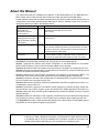
This manual describes the installation and operation of the R88A-MCW151-E and R88A-MCW151DRT-E Motion Control Option Boards (MC Units) and includes the sections described below.
Please read this manual and the related manuals listed in the following table carefully and be sure you
understand the information provided before attempting to install or operate the MC Unit. Be sure to
read the precautions provided in the following section.
Name
MCW151 Series
R88A-MCW151-E
R88A-MCW151-DRT-E
Operation Manual
Cat. No.
I203
Contents
Describes the installation and operation of the R88A-MCW151-E
and MCW151-DRT-E Motion Control Units.
(This manual)
OMNUC W-series
I531
R88M-W❏ (AC Servomotors)
R88D-W❏ (AC Servo Drivers)
User’s manual
Describes the installation and operation of the W-series Servo Driver
and Servomotor.
DeviceNet Operation Manual
W267
Describes the configuration and construction of a DeviceNet network, including installation procedures and specifications for cables,
connectors, and other connection devices, as well as information on
the communications power supply.
DeviceNet Configurator Operation Manual
W328
Describes the operation of the DeviceNet Configurator to allocate
remote I/O areas according to application needs, as well as procedures to set up a DeviceNet network with more than one master.
Precautions provides general precautions for using the MC Unit and related devices.
Section 1 describes the features and system configuration of the R88A-MCW151-E and R88AMCW151-DRT-E Motion Control Units and concepts related to their operation.
Section 2 describes the MC Unit components and provides the information for installing the MC Unit.
Section 3 describes the different Motion Control features of the MCW151. Also the functionality of the
Servo Driver related commands are explained.
Section 4 describes the communication components of the MCW151-E and MCW151-DRT-E. The
functionality of the serial communication protocols and the DeviceNet interface are explained.
Section 5 provides an overview of the fundamentals of multitasking BASIC programs and the methods
by which programs are managed in the MC Unit.
Section 6 describes all commands, functions and parameters required for programing the motion control application using the MC Unit.
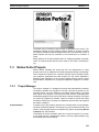
Section 7 describes the operation of the Motion Perfect programming software package. Motion Perfect provides the user a tool to program, monitor and debug motion based applications for the MC Unit.
Section 8 describes error processing and troubleshooting procedures needed to keep the system
operating properly.
Section 9 explains the maintenance and inspection procedures that must be followed to keep the MC
Unit operating in optimum condition. It also includes proper procedures when replacing an MC Unit.
The Appendices provide the required parameter settings for the Servo Driver, the DeviceNet protocol
specification and some general programming examples.
!WARNING
Failure to read and understand the information provided in this manual may result in personal injury or death, damage to the product, or product failure. Please read each section
in its entirety and be sure you understand the information provided in the section and
related sections before attempting any of the procedures or operations given.
vii
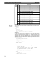
TABLE OF CONTENTS
PRECAUTIONS . . . . . . . . . . . . . . . . . . . . . . . . . . . . . . . .
xi
1
Intended Audience . . . . . . . . . . . . . . . . . . . . . . . . . . . . . . . . . . . . . . . . . . . . . . . . .
xii
2
General Precautions . . . . . . . . . . . . . . . . . . . . . . . . . . . . . . . . . . . . . . . . . . . . . . . .
xii
3
General Warnings and Safety Precautions . . . . . . . . . . . . . . . . . . . . . . . . . . . . . . .
xii
4
Storage and Transportation Precautions . . . . . . . . . . . . . . . . . . . . . . . . . . . . . . . . .
xiv
5
Installation and Wiring Precautions . . . . . . . . . . . . . . . . . . . . . . . . . . . . . . . . . . . .
xiv
6
Operation and Adjustment Precautions. . . . . . . . . . . . . . . . . . . . . . . . . . . . . . . . . .
xv
7
Maintenance and Inspection Precautions . . . . . . . . . . . . . . . . . . . . . . . . . . . . . . . .
xv
8
Conformance to EC Directives . . . . . . . . . . . . . . . . . . . . . . . . . . . . . . . . . . . . . . . .
xv
SECTION 1
Features and System Configuration . . . . . . . . . . . . . . . .
1
1-1
Features . . . . . . . . . . . . . . . . . . . . . . . . . . . . . . . . . . . . . . . . . . . . . . . . . . . . . . . . . .
2
1-2
System Configuration . . . . . . . . . . . . . . . . . . . . . . . . . . . . . . . . . . . . . . . . . . . . . . .
5
1-3
Motion Control Concepts . . . . . . . . . . . . . . . . . . . . . . . . . . . . . . . . . . . . . . . . . . . .
7
1-4
Control System Configuration . . . . . . . . . . . . . . . . . . . . . . . . . . . . . . . . . . . . . . . .
14
1-5
Specifications . . . . . . . . . . . . . . . . . . . . . . . . . . . . . . . . . . . . . . . . . . . . . . . . . . . . .
19
1-6
Comparison between Firmware Versions . . . . . . . . . . . . . . . . . . . . . . . . . . . . . . . .
21
SECTION 2
Installation . . . . . . . . . . . . . . . . . . . . . . . . . . . . . . . . . . . . .
23
2-1
Components and Unit Settings . . . . . . . . . . . . . . . . . . . . . . . . . . . . . . . . . . . . . . . .
24
2-2
Installation. . . . . . . . . . . . . . . . . . . . . . . . . . . . . . . . . . . . . . . . . . . . . . . . . . . . . . . .
28
2-3
Wiring . . . . . . . . . . . . . . . . . . . . . . . . . . . . . . . . . . . . . . . . . . . . . . . . . . . . . . . . . . .
30
2-4
Servo System Precautions . . . . . . . . . . . . . . . . . . . . . . . . . . . . . . . . . . . . . . . . . . . .
39
2-5
Wiring Precautions . . . . . . . . . . . . . . . . . . . . . . . . . . . . . . . . . . . . . . . . . . . . . . . . .
40
SECTION 3
Motion Control Functions . . . . . . . . . . . . . . . . . . . . . . . .
43
3-1
Overview . . . . . . . . . . . . . . . . . . . . . . . . . . . . . . . . . . . . . . . . . . . . . . . . . . . . . . . . .
44
3-2
System Set-up . . . . . . . . . . . . . . . . . . . . . . . . . . . . . . . . . . . . . . . . . . . . . . . . . . . . .
46
3-3
System Functions . . . . . . . . . . . . . . . . . . . . . . . . . . . . . . . . . . . . . . . . . . . . . . . . . .
47
SECTION 4
Communication Interfaces . . . . . . . . . . . . . . . . . . . . . . . .
59
4-1
Serial Communications . . . . . . . . . . . . . . . . . . . . . . . . . . . . . . . . . . . . . . . . . . . . . .
60
4-2
DeviceNet (MCW151-DRT-E only) . . . . . . . . . . . . . . . . . . . . . . . . . . . . . . . . . . . .
68
ix
TABLE OF CONTENTS
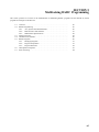
SECTION 5
Multitasking BASIC Programming. . . . . . . . . . . . . . . . .
85
5-1
Overview . . . . . . . . . . . . . . . . . . . . . . . . . . . . . . . . . . . . . . . . . . . . . . . . . . . . . . . .
86
5-2
BASIC Programming. . . . . . . . . . . . . . . . . . . . . . . . . . . . . . . . . . . . . . . . . . . . . . .
86
5-3
Motion Execution . . . . . . . . . . . . . . . . . . . . . . . . . . . . . . . . . . . . . . . . . . . . . . . . .
89
5-4
Command Line Interface . . . . . . . . . . . . . . . . . . . . . . . . . . . . . . . . . . . . . . . . . . . .
90
5-5
BASIC Programs . . . . . . . . . . . . . . . . . . . . . . . . . . . . . . . . . . . . . . . . . . . . . . . . . .
90
5-6
Task Operation Sequence . . . . . . . . . . . . . . . . . . . . . . . . . . . . . . . . . . . . . . . . . . .
93
5-7
Error Processing. . . . . . . . . . . . . . . . . . . . . . . . . . . . . . . . . . . . . . . . . . . . . . . . . . .
94
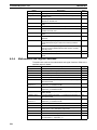
SECTION 6
BASIC Motion Control Programming Language . . . . .
97
6-1
Overview . . . . . . . . . . . . . . . . . . . . . . . . . . . . . . . . . . . . . . . . . . . . . . . . . . . . . . . .
102
6-2
Command Reference List . . . . . . . . . . . . . . . . . . . . . . . . . . . . . . . . . . . . . . . . . . .
103
6-3
Command, function and parameter description. . . . . . . . . . . . . . . . . . . . . . . . . . .
111
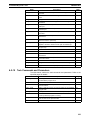
SECTION 7
Motion Perfect Software Package . . . . . . . . . . . . . . . . . .
197
7-1
Features and Requirements . . . . . . . . . . . . . . . . . . . . . . . . . . . . . . . . . . . . . . . . . .
198
7-2
Connecting to the MC Unit . . . . . . . . . . . . . . . . . . . . . . . . . . . . . . . . . . . . . . . . . .
198
7-3
Motion Perfect Projects . . . . . . . . . . . . . . . . . . . . . . . . . . . . . . . . . . . . . . . . . . . . .
199
7-4
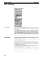
Desktop Appearance . . . . . . . . . . . . . . . . . . . . . . . . . . . . . . . . . . . . . . . . . . . . . . .
201
7-5
Motion Perfect Tools . . . . . . . . . . . . . . . . . . . . . . . . . . . . . . . . . . . . . . . . . . . . . . .
204
7-6
Suggestions and Precautions . . . . . . . . . . . . . . . . . . . . . . . . . . . . . . . . . . . . . . . . .
217
SECTION 8
Troubleshooting. . . . . . . . . . . . . . . . . . . . . . . . . . . . . . . . .
219
8-1
Error Indicators . . . . . . . . . . . . . . . . . . . . . . . . . . . . . . . . . . . . . . . . . . . . . . . . . . .
220
8-2
Error Handling . . . . . . . . . . . . . . . . . . . . . . . . . . . . . . . . . . . . . . . . . . . . . . . . . . . .
221
8-3
Problems and Countermeasures. . . . . . . . . . . . . . . . . . . . . . . . . . . . . . . . . . . . . . .
227
SECTION 9
Maintenance and Inspection. . . . . . . . . . . . . . . . . . . . . . .
233
9-1
Routine Inspections . . . . . . . . . . . . . . . . . . . . . . . . . . . . . . . . . . . . . . . . . . . . . . . .
234
9-2
Replacing a MC Unit . . . . . . . . . . . . . . . . . . . . . . . . . . . . . . . . . . . . . . . . . . . . . . .
235
Appendices
Appendix A
Servo Driver Parameter List . . . . . . . . . . . . . . . . . . . . . . . . . . . . . . . . .
237
Appendix B
Device Protocol (MCW151-DRT-E only). . . . . . . . . . . . . . . . . . . . . . .
239
Appendix C
Programming Examples. . . . . . . . . . . . . . . . . . . . . . . . . . . . . . . . . . . . .
245
Index . . . . . . . . . . . . . . . . . . . . . . . . . . . . . . . . . . . . . . . . . .
255
Revision History . . . . . . . . . . . . . . . . . . . . . . . . . . . . . . . .
261
x
PRECAUTIONS
This section provides general precautions for using the Motion Control Unit and related devices.
The information contained in this section is important for the safe and reliable application of the Motion Control
Unit. You must read this section and understand the information contained before attempting to set up or operate
a Motion Control Unit and Servo Driver.
1
2
3
4
5
6
7
8
Intended Audience . . . . . . . . . . . . . . . . . . . . . . . . . . . . . . . . . . . . . . . . . . . . .
General Precautions . . . . . . . . . . . . . . . . . . . . . . . . . . . . . . . . . . . . . . . . . . . .
General Warnings and Safety Precautions . . . . . . . . . . . . . . . . . . . . . . . . . . .
Storage and Transportation Precautions . . . . . . . . . . . . . . . . . . . . . . . . . . . . .
Installation and Wiring Precautions . . . . . . . . . . . . . . . . . . . . . . . . . . . . . . . .
Operation and Adjustment Precautions. . . . . . . . . . . . . . . . . . . . . . . . . . . . . .
Maintenance and Inspection Precautions . . . . . . . . . . . . . . . . . . . . . . . . . . . .
Conformance to EC Directives . . . . . . . . . . . . . . . . . . . . . . . . . . . . . . . . . . . .
8-1
Concepts . . . . . . . . . . . . . . . . . . . . . . . . . . . . . . . . . . . . . . . . . . . . . .
8-1-1 Conformance to EC Directives . . . . . . . . . . . . . . . . . . . . . . . . . . . . .
xii
xii
xii
xiv
xiv
xv
xv
xv
xvi
xvi
xi
Intended Audience
1
1
Intended Audience
This manual is intended for the following personnel, who must also have knowledge of electrical systems (an electrical engineer or the equivalent).
• Personnel in charge of installing FA systems.
• Personnel in charge of designing FA systems.
• Personnel in charge of managing FA systems and facilities.
2
General Precautions
The user must operate the product according to the performance specifications described in
the operation manuals. You should assume that anything not described in this manual is not
possible.
Before using the product under the following conditions, consult your OMRON representative,
make sure the ratings and performance characteristics of the products are good enough for
the systems, machines, or equipment, and be sure to provide the systems, machines, or
equipment with double safety mechanisms.
1. Conditions not described in the manual.
2. The application of the product to nuclear control systems, railroad systems, aviation systems, vehicles, combustion systems, medical equipment, amusement machines, or safety
equipment.
3. The application of the product to systems, machines, or equipment that may have a serious
influence on human life and property if they are used improperly.
!WARNING
3
It is extremely important that Motion Control Units and related devices be used for the
specified purpose and under the specified conditions, especially in applications that can
directly or indirectly affect human life. You must consult with your OMRON representative
before applying Motion Control Units and related devices to the above mentioned applications.
General Warnings and Safety Precautions
Observe the following warnings when using the MC Unit and all pheripheral devices.
Consult your OMRON representative when using the product after a long period of storage.
!WARNING
!WARNING
!WARNING
!WARNING
!WARNING
!WARNING
!WARNING
xii
Always connect the frame ground terminals of the Servo Driver and the Servomotor to a
class-3 ground (to 100 Ω or less). Not connecting to a class-3 ground may result in electric shock.
The product contains dangerous high voltage inside. Turn OFF the power and wait for at
least five minutes to allow power to discharge before handling or working with the product.
Do not touch the inside of the Servo Driver. Doing so may result in electric shock.
Do not remove the front cover, terminal covers, cables, Parameter Units, or optional
items while the power is being supplied. Doing so may result in electric shock.
Installation, operation, maintenance, or inspection must be performed by authorized personnel. Not doing so may result in electric shock or injury.
Wiring or inspection must not be performed for at least five minutes after turning OFF the
power supply. Doing so may result in electric shock.
Do not damage, press, or put excessive stress or heavy objects on the cables. Doing so
may result in electric shock, stopping operation of the product, or burning.
General Warnings and Safety Precautions
!WARNING
!WARNING
!WARNING
3
Do not touch the rotating parts of the Servomotor in operation. Doing so may result in
injury.
Do not modify the product. Doing so may result in injury or damage to the product.
Provide safety measures in external control circuits (i.e., not in the MC Unit) to ensure
safety in the system if an abnormality occurs due to malfunction of the MC Unit, incorrect
or unintended configuration and programming of the MC Unit or external factors affecting
the operation of the MC Unit. Not providing sufficient safety measures may result in serious accidents, or property damage.
• The MC Unit outputs may remain ON or OFF due to deposits on or burning of the output relays, or destruction of the output transistors. As a counter-measure for such problems, external safety measures must be provided to ensure safety in the system.
• Provide an external emergency stopping device that allows an instantaneous stop of
operation and power interruption. Not doing so may result in injury.
• Emergency stop circuits, interlock circuits, limit circuits, and similar safety measures
must be provided in external control circuits.
• When the 24-VDC output (service power supply to the Unit) is overloaded or short-circuited, the voltage may drop and result in the outputs being turned OFF. As a countermeasure for such problems, external safety measures must be provided to ensure
safety in the system.
!WARNING
!WARNING
!Caution
!Caution
!Caution
It is the nature of high speed motion control and motion control language programming
and multi-tasking systems, that it is not always possible for the system to validate the
inputs to the functions or to validate the combination of functions.
It is the responsibility of the programmer to ensure that the various BASIC statements are
invoked correctly with the correct number of parameters and inputs, that the values are
correctly validated prior to the actual calling of the functions, and that the BASIC program(s) provide the desired functionality for the application. Failure to do so may result in
unexpected behaviour, loss or damage to the machinery.
When the SERVO_PERIOD parameter has been set to change the servo cycle period of
the MC Unit, a power down or software reset (using DRV_RESET) must be performed for
the complete system. Not doing so may result in undefined behaviour.
Use the Servomotors and Servo Drivers in a specified combination. Using them incorrectly may result in fire or damage to the product.
Do not operate the control system in the following locations:
• Locations subject to direct sunlight.
• Locations subject to temperatures or humidity outside the range specified in the specifications.
• Locations subject to condensation due to radical temperature changes.
• Locations subject to corrosive or inflammable gases.
• Locations subject to dust (especially iron dust) or salts.
• Locations subject to vibration or shock.
• Locations subject to exposure to water, oil or chemicals.
!Caution
Do not touch the Servo Driver radiator, Regeneration Resistor, or Servomotor while the
power is being supplied or soon after power is turned OFF. Doing so may result in a skin
burn due to the hot surface.
xiii
Storage and Transportation Precautions
4
Storage and Transportation Precautions
!Caution
!Caution
!Caution
5
Do not hold the product by the cables or motor shaft while transporting it. Doing so may
result in injury or malfunction.
Do not place any load exceeding the figure indicated on the product. Doing so may result
in injury or malfunction.
Use the motor eye-bolts only for transporting the Motor. Using them for transporting the
machinery may result in injury or malfunction.
Installation and Wiring Precautions
!Caution
!Caution
!Caution
!Caution
!Caution
!Caution
!Caution
!Caution
!Caution
!Caution
!Caution
!Caution
Do not step or place a heavy object on the product. Doing so may result in injury.
Do not cover the inlet or outlet ports and prevent any foreign objects from entering the
product. Doing so may result in fire.
Be sure to install the product in the right direction. Not doing so may result in malfunction.
Provide the specified clearance between the Servo Driver and the control panel or with
other devices. Not doing so may result in fire or malfunction.
Do not apply any strong impact. Doing so may result in malfunction.
Be sure to wire correctly and securely. Not doing so may result in motor runaway, injury,
or malfunction.
Be sure that all mounting screws, terminal screws, and cable connector screws are tightened securely. Incorrect tightening may result in malfunction.
Use crimp terminals for wiring. Do not connect bare stranded wires directly to terminals.
Connection of bare stranded wires may result in fire.
Always use the power supply voltages specified in the manual. An incorrect voltage may
result in malfunction or burning.
Take appropriate measures to ensure that the specified power with the rated voltage and
frequency is supplied. Be particularly careful in places where the power supply is unstable. An incorrect power supply may result in malfunction.
Install external breakers and take other safety measures against short-circuiting in external wiring. Insufficient safety measures against short-circuiting may result in burning.
Take appropriate and sufficient countermeasures when installing systems in the following
locations. Not doing so may result in damage to the product.
•
•
•
•
!Caution
!Caution
xiv
4
Locations
Locations
Locations
Locations
subject to static electricity or other sources of noise.
subject to strong electromagnetic fields.
subject to possible exposure to radiation.
near power supply lines.
Do not reverse the polarity of the battery when connecting it. Reversing the polarity may
damage the battery or cause it to explode.
Before touching a Unit, be sure to first touch a grounded metallic object in order to discharge any static build-up. Not doing so may result in malfunction or damage.
Operation and Adjustment Precautions
6
6
Operation and Adjustment Precautions
!Caution
Confirm that no adverse effects will occur in the system before performing the test operation. Not doing so may result in damage to the product.
!Caution
Check the modified user programs, newly set parameters and switches for proper execution before actually running them. Not doing so may result in damage to the product.
!Caution
Do not make any extreme adjustments or setting changes. Doing so may result in unstable operation and injury.
!Caution
Separate the Servomotor from the machine, check for proper operation, and then connect to the machine. Not doing so may cause injury.
!Caution
When an alarm occurs, remove the cause, reset the alarm after confirming safety, and
then resume operation. Not doing so may result in injury.
!Caution
Do not come close to the machine immediately after resetting momentary power interruption to avoid an unexpected restart. (Take appropriate measures to secure safety against
an unexpected restart.) Doing so may result in injury.
!Caution
Confirm that no adverse effect will occur in the system before attempting any of the following. Not doing so may result in an unexpected operation or damage to the product.
• Changing the present values or set values.
• Changing the parameters.
• Modifying (one of) the application programs.
!Caution
Do not save data into the flash memory during memory operation or while the motor is
running. Otherwise, unexpected operation may be caused.
!Caution
Do not turn OFF the power supply to the Unit while data is being written to flash memory.
Doing so may cause problems with the flash memory.
!Caution
Do not turn OFF the power supply to the Unit while data is being transferred. Doing so
may result in malfunction or damage to the product.
!Caution
7
Do not download any firmware to the MC Unit that has not been distributed by OMRON or
that has not been authorized and approved by OMRON for downloading into the
MCW151 series. Failure to do so may result in permanent or temporary malfunction of
the Unit or unexpected behaviour.
Maintenance and Inspection Precautions
!WARNING
!Caution
8
Do not attempt to disassemble, repair, or modify any Units. Any attempt to do so may
result in malfunction, fire, electric shock, or injury.
Resume operation only after transferring to the new Unit the contents of the data required
for operation. Not doing so may result in an unexpected operation or damage to the product.
Conformance to EC Directives
Applicable Directives
• EMC Directives
• Low Voltage Directive
xv
8
Conformance to EC Directives
8-1
Concepts
EMC Directives
OMRON devices that comply with EC Directives also conform to the related EMC standards
so that they can be more easily built into other devices or ma-chines. The actual products
have been checked for conformity to EMC standards (see the following note). Whether the
products conform to the standards in the system used by the customer, however, must be
checked by the customer. EMC-related performance of the OMRON devices that comply with
EC Directives will vary depending on the configuration, wiring, and other conditions of the
equipment or control panel in which the OMRON devices are installed. The customer must,
therefore, perform final checks to confirm that devices and the over-all machine conform to
EMC standards.
Note
Applicable EMC (Electromagnetic Compatibility) standards are as follows:
EMS (Electromagnetic Susceptibility):
EMI (Electromagnetic Interference):
EN61000-6-2, EN50082-2
EN55011 Class A Group 1
Low Voltage Directive
Always ensure that devices operating at voltages of 50 to 1,000 VAC or 75 to 1,500 VDC meet
the required safety standards.
8-1-1
Conformance to EC Directives
The W-series Servo Driver complies with EC Directives. To ensure that the machine or device
in which a Servo Driver and MC Unit are used complies with EC directives, the Servo System
must be installed as follows (refer to OMNUC W-series User’s manual (I531)):
1,2,3...
xvi
1. The Servo Driver must be mounted in a metal case (control box). (It is not necessary to
mount the Servomotor in a metal box.)
2. Noise filters and surge absorbers must be inserted in power supply lines.
3. Shielded cable must be used for I/O signal cables and encoder cables. (Use soft steel wire.)
4. Cables leading out from the control box must be enclosed within metal ducts or conduits
with blades.
5. Ferrite cores must be installed for cables with braided shields, and the shield must be directly grounded to a ground plate.
SECTION 1
Features and System Configuration
This section describes the features and system configuration of the R88A-MCW151-E and R88A-MCW151-DRT-E
Motion Control Units and concepts related to their operation.
1-1
1-2
1-3
1-4
1-5
1-6
Features . . . . . . . . . . . . . . . . . . . . . . . . . . . . . . . . . . . . . . . . . . . . . . . . . . . . . .
1-1-1 Overview. . . . . . . . . . . . . . . . . . . . . . . . . . . . . . . . . . . . . . . . . . . . . .
1-1-2 Description of Features. . . . . . . . . . . . . . . . . . . . . . . . . . . . . . . . . . .
System Configuration . . . . . . . . . . . . . . . . . . . . . . . . . . . . . . . . . . . . . . . . . . .
Motion Control Concepts . . . . . . . . . . . . . . . . . . . . . . . . . . . . . . . . . . . . . . . .
1-3-1 PTP-control. . . . . . . . . . . . . . . . . . . . . . . . . . . . . . . . . . . . . . . . . . . .
1-3-2 CP-control. . . . . . . . . . . . . . . . . . . . . . . . . . . . . . . . . . . . . . . . . . . . .
1-3-3 EG-Control . . . . . . . . . . . . . . . . . . . . . . . . . . . . . . . . . . . . . . . . . . . .
1-3-4 Other Operations. . . . . . . . . . . . . . . . . . . . . . . . . . . . . . . . . . . . . . . .
Control System Configuration . . . . . . . . . . . . . . . . . . . . . . . . . . . . . . . . . . . .
1-4-1 Servo System Principles . . . . . . . . . . . . . . . . . . . . . . . . . . . . . . . . . .
1-4-2 Encoder Signals . . . . . . . . . . . . . . . . . . . . . . . . . . . . . . . . . . . . . . . .
Specifications . . . . . . . . . . . . . . . . . . . . . . . . . . . . . . . . . . . . . . . . . . . . . . . . .
1-5-1 General Specifications . . . . . . . . . . . . . . . . . . . . . . . . . . . . . . . . . . .
1-5-2 Functional Specifications . . . . . . . . . . . . . . . . . . . . . . . . . . . . . . . . .
1-5-3 DeviceNet Specifications (MCW151-DRT-E only) . . . . . . . . . . . . .
Comparison between Firmware Versions . . . . . . . . . . . . . . . . . . . . . . . . . . . .
2
2
3
5
7
8
10
11
13
14
14
17
19
19
19
21
21
1
Section 1-1
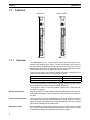
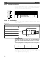
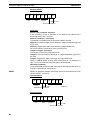
Features
Features
MCW151-E
MCW151-DRT
MCW151
RUN
STS
RUN
STS
RD
MS
NS
PORT2
PORT0,1
SD
MCW151-DRT-E
PORT0,1
1-1
1
2
1
I/O
I/O
25
1-1-1
26
2
25
26
+ 24 V
+ 2 4V
0V
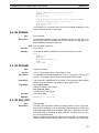
0V
Overview
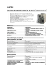
The R88A-MCW151 is a 1.5-axis Motion Control (MC) Unit which is connected to the W-series Servo Driver. The MC Unit provides direct control of
the Servo Driver, enables both speed and torque control and has access to
detailed Servo Driver data. To support a multi-axis control application, the MC
Unit features both an encoder input and output connection.
There are two types of the MCW151 Motion Controllers, according to the
communication interface which is integrated into the Unit.
Communication Interface
Model
RS-422A/485 Serial Communication
R88A-MCW151-E
DeviceNet
R88A-MCW151-DRT-E
The multi-tasking BASIC motion control language provides an easy to use
tool for programming advanced motion control applications.
Three types of motion control are possible: point-to-point, continuous path
and electronic gearing.
Point-to-point Control
Point-to-point (PTP) control enables positioning independently for each axis.
Axis specific parameters and commands are used to determine the paths for
the axes.
Continuous Path Control
Continuous path (CP) control enables the user not only to control the start and
end positions, but also the path between those points. Possible multi-axis
paths are linear interpolation and circular interpolation. Also user defined
paths can be realized with the CAM control.
Electronic Gearing
Electronic gearing (EG) enables controlling an axis as a direct link to another
axis. The MC Units supports electronic gear boxing, linked moves and CAM
movements and adding all movements of one axis to another.
2
Section 1-1
Features
1-1-2
Description of Features
The MC Unit provides the following features.
Motion Control
The direct connection to the Servo Driver provides a high performance / high
precision control system. Operation will be processed in optimal synchronization.
• Supports both speed and torque control modes of the Servo Driver.
• Supports switching between the modes during operation.
• Supports speed limit during torque control using the speed reference.
• Selectable MC Unit servo period cycle which can be set to either 0.5 ms
or 1.0 ms.
Servo Driver Access
Apart from the motion control operation with the Servo Driver, the MC Unit
provides the following features:
• Monitor the detailed Servo Driver alarm status.
• Monitor various monitor signals (rotation speed, command torque).
• Monitor the Servo Driver digital inputs and analog input to include in the
application.
• Read and write of the Servo Driver Parameters.
• Execution of several Driver functions from the MC Unit. Examples are
Print Registration, Origin Search, Driver Alarm Reset and Driver Reset.
Easy Programming with
BASIC Motion Control
Language
The multi-task BASIC motion control language is used to program the MC
Unit. A total of 14 programs can be held in the Unit and up to 3 tasks can be
run simultaneously. The MC Unit is programmed using a Windows-based
application called 1Motion Perfect. Motion Perfect allows extremely flexible
programming and debugging.
Encoder Input and Output
To achieve a solution for multi-axis applications, the MC Unit is provided with
an encoder axis. This axis provides either to have an encoder input for external encoders or to have an encoder output to cascade position data to
another MC Unit.
DeviceNet Interface
(MCW151-DRT-E only)
The MCW151-DRT-E can be connected easily in an existing DeviceNet network. The DeviceNet network has a maximum communication distance of
500 m, so an MC Unit in a remote location can be controlled from the Master.
The MC Unit supports both remote I/O and explicit message communications.
• Remote I/O communications
Remote I/O communications can exchange data (4 input words and 4 output words max.) with the MC Unit at high speed and without programming, just like regular I/O.
• Explicit message communications
Large data transfers to and from the MC Unit memory can be performed
by sending explicit messages from the Master when required.
Serial Communications
The MC Unit has three (MCW151-E) or two (MCW151-DRT-E) serial ports for
communication to several external devices. Next to the connection to the Personal Computer for configuring, the MC Unit can be connected with PCs, Programming Terminals (PTs) and other MC Units. The serial ports support the
Host Link Master and Slave protocols.
Absolute Encoder
Support
By using a Servomotor with absolute encoder, the motor position is updated
automatically in the MC Unit at start-up of the system. No origin search
sequence will be necessary in the system initiation phase.
1.Motion Perfect is a product of Trio Motion Technology Limited.
3
Section 1-1
Features
Virtual Axes
The MC Unit contains a total of 3 axes, of which two can be configured as virtual axis. The virtual axes are internal axes and are used for computational
purposes. They act as perfect servo axes and are very useful for creating profiles. They can be linked directly to the servo axes.
Hardware-based
Registration Inputs
There is a high-speed registration input for the encoder input and output axis.
On the rising or falling edge of a registration input, the MC Unit will store the
current position in a register. The registered position can then be used by the
BASIC program as required. The registered positions are captured in hardware.
General-purpose Input
and Output Signals
Starting, stopping, limit switching, origin searches and many other functions
can be controlled by the MC Unit. The general I/O can have specific functions
(such as the registration, limit switches), but also can be freely used.
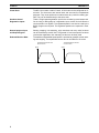
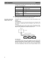
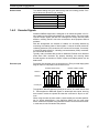
Reduced Machine Wear
The traditional trapezoidal speed profile is provided to generate smooth starting and stopping. The trapezoidal corners can be rounded off to S-curves.
Trapezoidal Speed Profile with
Square Corners
Trapezoidal Speed Profile with
S-curve Corners
Speed
Speed
Time
4
Time
Section 1-2
System Configuration
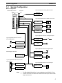
1-2
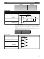
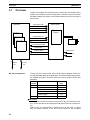
System Configuration
Basic Configuration
W-series Servo Driver
MCW151
Personal
Computer
M CW15 1
RUN
ST S
RD
PORT2
PORT0 ,1
SD
Personal Computer running Motion Perfect
1
1
Typical applicable Units for Serial Comm. Ports
2
PC
I/O
2
25
26
Programmable
Terminal (PT)
+ 24 V
0V
General-purpose
device
Typical applicable Actuators for Digital Outputs
Typical applicable Sensors for Servo
Driver Digital Inputs
Relais
Print Registration
Lamp
Limit Switches
Typical applicable Sensors for Digital Inputs
Power Supply connection
Print Registration
24 V Power supply
Proximity Sensor
Typical applicable Pulse Generators for
Encoder Input
Typical applicable Units for Encoder Output
MCW151 Unit
MCW151 Unit
Servo Driver
Note
1. The RS-422A/485 Serial Port 2 is only available on the MCW151-E Unit.
2. The MC Unit has one encoder axis. Either the encoder input or the encoder
output can be used.
5
Section 1-2
System Configuration
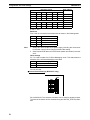
The equipment and models which can be used in the system configuration
are shown in the following table.
Device
Model
Motion Control Unit
R88A-MCW151-E
R88A-MCW151-DRT-E
Servo Driver (see note)
R88D-WT❏
Servomotor
R88M-W❏
Control Devices (using
Host Link)
Programmable Terminals
CPU Units
Personal Computer (for
Motion Perfect)
IBM Personal Computer or 100% compatible
Motion Perfect
Version 2.0 or later
Note The MC Unit must be used with a Servo Driver with software version 14 or
later. The MC Unit cannot be used with software version 8.
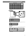
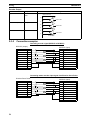
DeviceNet Configuration
(MCW151-DRT-E only)
A DeviceNet system can be constructed in two ways: fixed allocation or free
allocation.
Fixed Allocation
A DeviceNet system can be constructed easily without the Configurator. With
fixed allocation, predetermined words are allocated to each node for the
Slave’s I/O.
An OMRON Master must be used in order to perform fixed allocation. Moreover, with fixed allocation only one Master Unit can be used in a DeviceNet
network and only one Master Unit may be mounted to a PC.
Master Unit
CPU Unit
Remote I/O communications
Slave
Slave
MC Unit
Free Allocation
The Configurator can be used to freely allocate the words used by each
Slave. With free allocation, more than one Master Unit can be connected in a
DeviceNet network and each Master’s Slave I/O can be set independently.
More than one Master Unit may be mounted to each PC and those Masters
can be used independently. Furthermore, other companies’ Masters can be
6
Section 1-3
Motion Control Concepts
used. For details, refer to the DeviceNet Configurator Operation Manual
(W328).
Master Unit
Master Unit
Master Unit
Configurator
CPU Unit
ISA Board
Message
communications
Remote I/O communications
MC Unit
Slave
Slave
MC Unit
The following OMRON Master Units can be used.
Applicable PC
Master Unit model
number
Mounting position
Max. number of Units
With
Configurator
Without
Configurator
CS1 Series
CS1-DRM21
CPU Rack or Expansion I/O Rack
(Classified as Special I/O Units)
16
1
C200HZ/HX/HG/HE
C200HW-DRM21-V1
CPU Rack or Expansion I/O Rack
(Classified as Special I/O Units)
10 or 16 (see
note)
1
Note Some CPUs can control 16 Master Units and other CPUs can control 10.
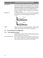
1-3
Motion Control Concepts
The MC Unit offers the following types positioning control operations.
1. Point-to-point control
2. Continuous Path control
3. Electronic Gearing
This section will introduce some of the commands and parameters as used in
the BASIC programming of the motion control application. Refer to
SECTION 6 BASIC Motion Control Programming Language for details.
Coordinate System
Positioning operations performed by the MC Unit are based on an axis coordinate system. The MC Unit converts the position data from either the connected Servo Driver or the connected encoder into an internal absolute
coordinate system.
The engineering unit which specifies the distances of travelling can be freely
defined for each axis separately. The conversion is performed through the
use of the unit conversion factor, which is defined by the UNITS axis parameter. The origin point of the coordinate system can be determined using the
DEFPOS command. This command re-defines the current position to zero or
any other value.
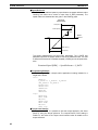
A move is defined in either absolute or relative terms. An absolute move takes
the axis to a specific predefined position with respect to the origin point. A relative move takes the axis from the current position to a position that is defined
relative to this current position. The following diagram shows gives an exam-
7
Section 1-3
Motion Control Concepts
ple of relative (command MOVE) and absolute (command MOVEABS) linear
moves.
MOVEABS(30)
MOVE(60)
MOVEABS(50)
MOVE(50)
MOVE(30)
0
1-3-1
50
100
Axis position
PTP-control
In point-to-point positioning, each axis is moved independently of the other
axis. The MC Unit supports the following operations.
• Relative move
• Absolute move
• Continuous move forward
• Continuous move reverse
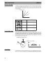
Relative and Absolute Moves
To move a single axis either the command MOVE for a relative move or the
command MOVEABS for an absolute move is used. Each axis has its own
move characteristics, which are defined by the axis parameters.
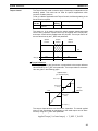
Suppose a control program is executed to move from the origin to an axis
no. 0 coordinate of 100 and axis no. 1 coordinate of 50. If the speed parameter is set to be the same for both axes and the acceleration and deceleration
rate are set sufficiently high, the movements for axis 0 and axis 1 will be as
illustrated below.
MOVEABS(100) AXIS(0)
MOVEABS(50) AXIS(1)
Axis 1
50
0
50
100
Axis 0
At start, both the axis 0 and axis 1 will move to a coordinate of 50 over the
same duration of time. At this point, axis 1 will stop and the axis 0 will continue to move to a coordinate of 100.
Relevant Axis Parameters
As mentioned before the move of a certain axis is determined by the axis
parameters. Some relevant parameters are given in the next table.
Parameter
8
Description
UNITS
Unit conversion factor
ACCEL
Acceleration rate of an axis in units/s2
DECEL
Deceleration rate of an axis in units/s2
SPEED
Demand speed of an axis in units/s
Section 1-3
Motion Control Concepts
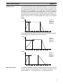
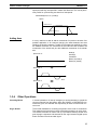
Defining moves
The speed profile below shows a simple MOVE operation. The UNITS parameter for this axis has been defined for example as meters. The required maximum speed has been set to 10 m/s. In order to reach this speed in one
second and also to decelerate to zero speed again in one second, both the
acceleration as the deceleration rate have been set to 10 m/s2. The total distance travelled is the sum of distances travelled during the acceleration, constant speed and deceleration segments. Suppose the distance moved by the
MOVE command is 40 m, the speed profile will be given by the following
graph.
Speed
ACCEL=10
DECEL=10
SPEED=10
MOVE(40)
10
0
1
2
3
4
5
6
Time
The following two speed profiles show the same movement with an acceleration time respectively a deceleration time of 2 seconds.
Speed
ACCEL=5
DECEL=10
SPEED=10
MOVE(40)
10
0
1
2
3
4
5
6
Time
Speed
ACCEL=10
DECEL=5
SPEED=10
MOVE(40)
10
0
Move Calculations
1
2
3
4
5
6
Time
The following equations are used to calculate the total time for the motion of
the axes. Consider the moved distance for the MOVE command as D , the
demand speed as V , the acceleration rate a and deceleration rate d .
9
Section 1-3
Motion Control Concepts
Acceleration time
Acceleration distance
Deceleration time
Deceleration distance
= V
--a
2
V= ----2a
V
= --d
2
V
= -----2d
2
Constant speed distance
Total time
( a + d )= D–V
---------------------2ad
D V (a + d )
= ---- + --------------------V
2ad
Continuous Moves
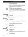
The FORWARD and REVERSE commands can be used to start a continuous
movement with constant speed on a certain axis. The FORWARD command
will move the axis in positive direction and the REVERSE command in negative direction. For these commands also the axis parameters ACCEL and
SPEED apply to specify the acceleration rate and demand speed.
Both movements can be canceled by using either the CANCEL or RAPIDSTOP command. The CANCEL command will cancel the move for one axis
and RAPIDSTOP will cancel moves on all axes. The deceleration rate is set
by DECEL.
1-3-2
CP-control
Continuous Path control enables to control a specified path between the start
and end position of a movement for one or multiple axes. The MC Unit supports the following operations.
• Linear interpolation
• Circular interpolation
• CAM control
Linear Interpolation
In applications it can be required for a set of motors to perform a move operation from one position to another in a straight line. Linearly interpolated moves
can take place among several axes. The commands MOVE and MOVEABS
are also used for the linear interpolation. In this case the commands will have
multiple arguments to specify the relative or absolute move for each axis.
Consider the following three axis move in a 3-dimensional plane.
MOVE(50,50,50)
Axis 2
Speed
Axis 1
Time
Axis 0
10
Section 1-3
Motion Control Concepts
The speed profile of the motion along the path is given in the diagram. The
three parameters SPEED, ACCEL and DECEL which determine the multi axis
movement are taken from the corresponding parameters of the base axis.
The MOVE command computes the various components of speed demand
per axis.
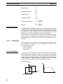
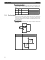
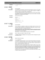
Circular Interpolation
It may be required that a tool travels from the starting point to the end point in
an arc of a circle. In this instance the motion of two axes is related via a circular interpolated move using the MOVECIRC command. Consider the following
diagram.
MOVECIRC(-100,0,-50,0,0)
Axis 1
50
-50
0
50
Axis 0
The centre point and desired end point of the trajectory relative to the start
point and the direction of movement are specified. The MOVECIRC command
computes the radius and the angle of rotation. Like the linearly interpolated
MOVE command, the ACCEL, DECEL and SPEED variables associated with
the base axis determine the speed profile along the circular move.
CAM Control
Additional to the standard move profiles the MC Unit also provides a way to
define a position profile for the axis to move. The CAM command will move an
axis according to position values stored in the MC Unit Table array. The
speed of travelling through the profile is determined by the axis parameters of
the axis.
CAM(0,99,100,20)
Position
Time
1-3-3
EG-Control
Electronic Gearing control allows you to create a direct gearbox link or a
linked move between two axes. The MC Unit supports the following operations.
1. Electronic gearbox
2. Linked CAM
3. Linked move
4. Adding axes
11
Section 1-3
Motion Control Concepts
Electronic Gearbox
The MC Unit is able to have a gearbox link from one axis to another as if there
is a physical gearbox connecting them. This can be done using the CONNECT command in the program. In the command the ratio and the axis to link
to are specified.
CONNECT Axis
2:1
1:1
1:2
Master Axis
Axes
0
Ratio
CONNECT command
1
1:1
CONNECT(1,0) AXIS(1)
2:1
CONNECT(2,0) AXIS(1)
1:2
CONNECT(0.5,0) AXIS(1)
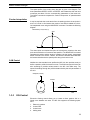
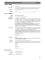
Linked CAM control
Next to the standard CAM profiling tool the MC Unit also provides a tool to link
the CAM profile to another axis. The command to create the link is called
CAMBOX. The travelling speed through the profile is not determined by the
axis parameters of the axis but by the position of the linked axis. This is like
connecting two axes through a cam.
CAMBOX(0,99,100,20,0) AXIS(1)
CAMBOX Axis (1) Position
Master Axis (0) Position
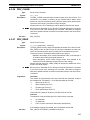
Linked Move
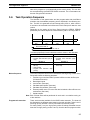
The MOVELINK command provides a way to link a specified move to a master axis. The move is divided into an acceleration, deceleration and constant
12
Section 1-3
Motion Control Concepts
speed part and they are specified in master link distances. This can be particularly useful for synchronizing two axes for a fixed period.
MOVELINK(50,60,10,10,1) AXIS(0)
Speed
Master Axis (1)
Synchronized
MOVELINK Axis (0)
Time
Adding Axes
It is very useful to be able to add all movements of one axis to another. One
possible application is for instance changing the offset between two axes
linked by an electronic gearbox. The MC Unit provides this possibility by using
the ADDAX command. The movements of the linked axis will consists of all
movements of the actual axis plus the additional movements of the master
axis.
BASE(0)
ADDAX(2)
FORWARD
MOVE(100) AXIS(2)
MOVE(-60) AXIS(2)
Speed axis 0*
Speed axis 2
+
Time
Speed axis 0
=
Time
Time
1-3-4
Other Operations
Canceling Moves
In normal operation or in case of emergency it can be necessary to cancel the
current movement from the buffers. When the CANCEL or RAPIDSTOP commands are given, the selected axis respectively all axes will cancel their current move.
Origin Search
The encoder feedback for controlling the position of the motor is incremental.
This means that all movement must be defined with respect to an origin point.
The DATUM command is used to set up a procedure whereby the MC Unit
goes through a sequence and searches for the origin based on digital inputs
and/or Z-marker from the encoder signal.
13
Section 1-4
Control System Configuration
Print Registration
The MC Unit can capture the position of an axis in a register when an event
occurs. The event is referred to as the print registration input. On the rising or
falling edge of an input signal, which is either the Z-marker or an input, the MC
Unit captures the position of an axis in hardware. This position can then be
used to correct possible error between the actual position and the desired
position. The print registration is set up by using the REGIST command.
The position is captured in hardware, and therefore there is no software overhead and no interrupt service routines, eliminating the need to deal with the
associated timing issues.
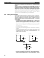
Merging Moves
If the MERGE axis parameter is set to 1, a movement will always be followed
by a subsequent movement without stopping. The following illustrations will
show the transitions of two moves with MERGE value 0 and value 1.
Speed
MERGE=0
Time
Speed
MERGE=1
Time
Jogging
1-4
1-4-1
Jogging moves the axes at a constant speed forward or reverse by manual
operation of the digital inputs. Different speeds are also selectable by input.
Refer to the FWD_JOG, REV_JOG and FAST_JOG axis parameters.
Control System Configuration
Servo System Principles
The servo system used by and the internal operation of the MC Unit are
briefly described in this section. Refer to 2-4 Servo System Precautions for
precautions related to servo system operation.
Semi-closed Loop System
14
The servo system of the MC Unit uses a semi-closed or inferred closed loop
system. This system detects actual machine movements by the rotation of the
motor in relation to a target value. It calculates the error between the target
value and actual movement, and reduces the error through feedback.
Section 1-4
Control System Configuration
MC Unit
Servo System
2
3
Demand
position
1
+
Position
Control
Speed
reference
Speed
Control
Motor
-
4
Measured
speed
Encoder
Measured
position
Internal Operation of the
MC Unit
1,2,3...
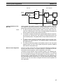
Motion Control Algorithm
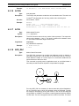
Inferred closed loop systems occupy the mainstream in modern servo systems applied to positioning devices for industrial applications. The following
graph shows the basic principle of the Servo System as used in the MC Unit.
1. The MC Unit performs actual position control. The main input of the controller is the following error, which is the calculated difference between the
demand position and the actual measured position.
2. The Position Controller calculates the required speed reference output determined by the following error and possibly the demanded position and
the measured position. The speed reference is provided to the Servo Driver.
3. The Servo Driver controls the rotational speed of the Servomotor corresponding to the speed reference. The rotational speed is proportional to
the speed reference.
4. The rotary encoder will generate the feedback pulses for both the speed
feedback within the Servo Driver speed loop and the position feedback
within the MC Unit position loop.
The servo system controls the motor by continuously adjusting the speed reference to the Servo Driver. The speed reference is calculated by the MC
Unit’s Motion Control algorithm, which is explained in this section.
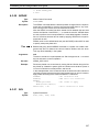
The Motion Control algorithm uses the demand position, the measured position and the following error to determine the speed reference. The following
error is the difference between the demanded and measured position. The
demand position, measured position and following error are represented by
axis parameters MPOS, DPOS and FE. Five gain values have been implemented for the user to be able to configure the correct control operation for
each application.
15
Section 1-4
Control System Configuration
The Motion Control algorithm of the MC Unit is shown in the diagram below.
Kvff∆
Kp
Demand
position
+
Following
error
-
Output
KiΣ
Kd ∆
+
+ signal
Kov∆
Measured
position
Proportional Gain
The proportional gain
following error E .
K p creates an output O p that is proportional to the
Op = K p ⋅ E
All practical systems use proportional gain. For many just using this gain
parameter alone is sufficient. The proportional gain axis parameter is called
P_GAIN.
Integral Gain
The integral gain K i creates an output O i that is proportional to the sum of
the following errors E that have occurred during the system operation.
Oi = Ki ⋅
åE
Integral gain can cause overshoot and so is usually used only on systems
working at constant speed or with slow accelerations. The integral gain axis
parameter is called I_GAIN.
Derivative Gain
The derivative gain K d produces an output O d that is proportional to the
change in the following error E and speeds up the response to changes in
error while maintaining the same relative stability.
O d = K d ⋅ ∆E
Derivative gain may create a smoother response. High values may lead to
oscillation. The derivative gain axis parameter is called D_GAIN.
Output Speed Gain
The output speed gain K ov produces an output O ov that is proportional to
the change in the measured position P m and increases system damping.
O ov = K ov ⋅ ∆P m
The output speed gain can be useful for smoothing motions but will generate
high following errors. The output speed gain axis parameter is called
OV_GAIN.
Speed Feedforward Gain
The speed feedforward gain K vff produces an output O vff that is proportional to the change in demand position P d and minimizes the following error
at high speed.
O vff = K vff ⋅ ∆Pd
The parameter can be set to minimise the following error at a constant
machine speed after other gains have been set. The speed feed forward gain
axis parameter is called VFF_GAIN.
16
Section 1-4
Control System Configuration
Default Values
The default settings are given below along with the resulting profiles. Fractional values are allowed for gain settings.
Gain
1-4-2
Default
Proportional Gain
0.1
Integral Gain
0.0
Derivative Gain
0.0
Output Speed Gain
0.0
Speed Feedforward Gain
0.0
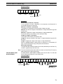
Encoder Signals
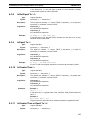
Standard OMRON equipment is designed for an advanced phase-A for forward rotation and an advanced phase-B for reverse rotation. For the encoder
input and output signals, the MC Unit is designed to comply with this phase
definition, allowing the MC Unit to be connected to other equipment without
problems.
With this arrangement, the direction of rotation can be easily detected by
monitoring the relative phase of both signals. If channel A leads channel B,
indicating clockwise (CW) movement, the counter will increment. Conversely,
if channel B leads channel A, indicating counterclockwise (CCW) movement,
the counter will decrement.
Typically, rotary encoders also provide an additional Z-marker as a reference
pulse within each revolution. By properly decoding and counting these
encoder signals, the direction of motion, speed, and relative position can be
determined.
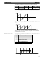
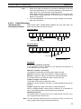
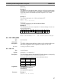
Encoder input
For the MC Unit encoder input, the pulse ratio is 4. Every encoder edge (pulse
edge for either A or B phase) is one internal count.
Forward rotation (CW)
Reverse rotation (CCW)
Phase A
Phase B
0
1
2
3
4
5
6
7
7
6
5
4
3
2
1
0
Counts (x4)
The signals A, B and Z appear physically as A+ and A-, B+ and B- and Z+ and
Z-. These appear as differential signals on twisted-pair wire inputs, ensuring
that common modes are rejected and that the noise level is kept to a minimum.
When using encoders by other makers, check carefully the encoder specification for phase advancement. If the definition differs from the ones given
above, reverse the B-phase wiring between the MC Unit and the Servo Driver.
In most case, this should resolve the problem.
17
Section 1-4
Control System Configuration
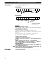
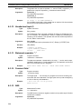
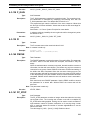
Encoder output
For encoder output, the pulse ratio is 64. For every 16 internal counts one
encoder edge for one of the two phases will be produced.
Phase A
Phase B
Phase Z
0
16 32 48 64 80 96
Internal Counts
The Z-phase signal has the following specification:
• The Z-marker has a period of 4096 generated edges.
• The pulse has a width of a quarter pulse period length (when both phase
A and B are low).
• The Z-phase signal is active after power-on.
The generated frequency is limited to the maximum allowable frequency. If
the internal speed would result in a frequency above this maximum, an axis
status flag will be set. See 8-2-1 MC Unit Error Handling for details.
18
Section 1-5
Specifications
1-5
1-5-1
Specifications
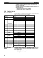
General Specifications
The MC Unit provides the following general specifications.
Item
Applicable Servo Driver
Servomotors
Type
Encoder
Installation Method
Basic Specifications
Contents
R88D-W Series (software version 14 or later, see note)
R88M-W Series
Incremental / Absolute
Mounted on the CN10 connector on the Servo Driver
side.
Power Supply Method
5 VDC (supplied from the control power supply of the
Servo Driver)
24 VDC (supplied from external power supply)
Total Power Consumption 4.0 W
Environment
External Dimensions
20 x 142 x 128 mm (H x W x D)
Approx. Mass
200 g
Current Consumption
170 mA for 24 VDC
Output Power Supply
5 VDC, maximum 160 mA (to external encoder)
Ambient Operating Temperature
0 to 55°C
Ambient Operating
Humidity
90 % RH or less (non-condensing)
Ambient Atmosphere
Free from corrosive gasses
Ambient Storage Temper- -20 to 75°C
ature
Ambient Storage Humidity 90 % RH or less (non-condensing)
Vibration Resistance
4.9 m/s2
Impact Resistance
Acceleration 19.6 m/s2 or less (when the impact is
applied three times in each X, Y, Z direction)
Note The MC Unit cannot be used with software version 8.
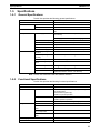
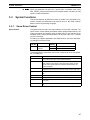
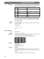
1-5-2
Functional Specifications
The MC Unit provides the following functional specifications.
Item
Type of Unit
Motion Control
Configuration
Contents
Optional board for W-series Servo Driver
Speed Control
Inferred closed loop with PID, output speed and speed
feed forward gains
Speed reference (open loop)
Possible torque limit operation
Torque Control
Torque reference
Possible speed limit operation
Control Switch
Speed / Torque control switching during operation
Maximum No. of axes
3
No. of controlled servo
axes
1
Maximum No. of encoder
in- or output axes
1
Maximum No. of virtual
axes
2
Servo Loop Cycle
Selectable to 0.5 ms or 1.0 ms.
Measurement Units
User definable
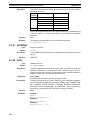
19
Section 1-5
Specifications
Item
Positioning operations
Linear interpolation for any number of axes
Circular interpolation
Circular interpolation for any two axes
CAM profile
CAM profile movement for any axis
Electronic gearbox
Electronic gearbox link between any two axes
Linked CAM
Linked CAM profile movement for any two axes
Linked move
Linked move for any two axes
Adding axes
Adding any two axes
Acceleration/deceleration curves
Trapezoidal or S-curve
Servo Driver Access
Motion Control
Speed Control
Torque Control
Position Feed-back
Driver Enable
Driver Print Registration
Monitoring
Driver Alarm and Warning Status
General Driver Status
Driver Digital Input
Driver Analogue Input
Driver Limit Switches
General Control
Driver Alarm Reset
Driver Reset
Parameter Access
Read and Write Pn-parameters
Read Un parameters
External connected devices
Personal Computer with Motion Perfect Programming
Software
Serial Communications RS-232C
Port 0:
Connection to PC (Motion Perfect Software)
Port 1:
Host Link Master protocol
Host Link Slave protocol
General-purpose
External
I/O
20
Contents
Linear interpolation
RS-422A/485 (MCW151E only)
Port 2:
Host Link Master protocol
Host Link Slave protocol
General-purpose
Encoder Input
Line receiver input; maximum response frequency:
1500 kHz pulses (before multiplication)
Pulse multiplication:
x4
Encoder Output
Line receive output; maximum frequency:
500 kHz pulses
Internal counts to output pulse ratio:
64 : 1
Digital Inputs
Total of 8 digital inputs can be wired and used for
instance for limit switches, emergency stop and proximity inputs. Two inputs can be used for registration of
the encoder input/output axis.
Digital Outputs
Total of 6 digital outputs can be wired and used for
position dependent switching or other general purposes.
Registration inputs
Two registration inputs can be used (simultaneously) to
capture the position in hardware.
Switch setting
DeviceNet settings (MCW151-DRT-E only)
General purpose (MCW151-E only)
Power supply for general and axis I/O
Provided externally
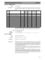
Section 1-6
Comparison between Firmware Versions
Item
Task program manage- Programming language
ment
Number of tasks
Contents
BASIC
Up to 3 tasks running simultaneously plus the Command Line task
Max. number of programs 14
Saving program data
Data storage capacity
251 (VR) + 8000 (Table) max.
MC Unit
Random Access Memory (RAM) and Flash memory
backup. (See note)
Personal Computer
Motion Perfect software manages a backup on the
hard disk of the personal computer.
Self diagnostic functions
Detection of memory corruption via checksum
Detection of error counter overrun
Note The service life for the flash memory is 100,000 writing operations.
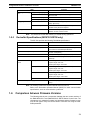
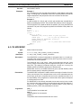
1-5-3
DeviceNet Specifications (MCW151-DRT-E only)
The MC Unit provides the following DeviceNet specifications.
Item
Contents
Communications protocol
DeviceNet
Supported connections (communications)
Master-Slave: Remote I/O and explicit messages
Both conform to DeviceNet specifications
Connection forms (see note)
Combination of multi-drop and T-branch connections
(for trunk or drop lines)
Baud rate
500 kbps, 250 kbps, 125 kbps (switchable)
Communications media
Special 5-wire cables (2 signal lines, 2 power lines, 1
shield line)
Communications distances
500 kbps
Network length: 100 m max. (100 m max.)
Drop line length: 6 m max.
Total drop line length: 39 m max.
250 kbps
Network length: 250 m max. (100 m max.)
Drop line length: 6 m max.
Total drop line length: 78 m max.
125 kbps
Network length: 500 m max. (100 m max.)
Drop line length: 6 m max.
Total drop line length: 156 m max.
Parentheses indicate the length when Thin Cables are used.
Communications power supply
11 to 25 VDC (Supplied from the communications connector)
Note Terminating resistors are required at both ends of trunk line.
Refer to the DeviceNet Operation Manual (W267) for other communication
specifications, such as communication cycle times.
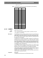
1-6
Comparison between Firmware Versions
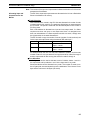
The following table shows a comparison between the two current versions of
the R88A-MCW151-E and R88A-MCW151-DRT-E Motion Control Units. The
changes are only related to firmware (not hardware) and the firmware is common for both types. Verify the current version of the MC Unit using the VERSION parameter.
21
Section 1-6
Comparison between Firmware Versions
!Caution
The R88A-MCW151-E FW 1.62 is fully backward compatible with the previous version FW 1.61. For the R88A-MCW151-DRT-E FW 1.62 many
DeviceNet implementation changes have been done. For both Units caution
must be taken when upgrading.
Item
22
FW 1.61
FW 1.62
Commands and
instructions
ADD_DAC
No.
Yes.
Command to enable dual feedback control.
DeviceNet
(MCW151-DRT-E
only)
Software reset of
MC Unit
Possible by either bit in
Remote I/O Output word 1 or
Explicit Message command
RESET.
Possibly only by Explicit Message command RESET.
Explicit messages
(read and write)
Different maximum transfer
amount for read and write.
Maximum amount of elements
to transfer (read/write) is 39
(three-word format) and 119
(one-word format).
See 4-2-2 Explicit DeviceNet
Messages.
Device objects
-
Update of Device objects.
See Appendix B Device Protocol (MCW151-DRT-E only).
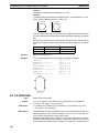
SECTION 2
Installation
This section describes the MC Unit components and provides the information required for installing the MC Unit.
2-1
2-2
2-3
2-4
2-5
Components and Unit Settings . . . . . . . . . . . . . . . . . . . . . . . . . . . . . . . . . . . .
Installation. . . . . . . . . . . . . . . . . . . . . . . . . . . . . . . . . . . . . . . . . . . . . . . . . . . .
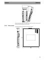
2-2-1 Installation Conditions . . . . . . . . . . . . . . . . . . . . . . . . . . . . . . . . . . .
2-2-2 Installation Method . . . . . . . . . . . . . . . . . . . . . . . . . . . . . . . . . . . . . .
2-2-3 Dimensions . . . . . . . . . . . . . . . . . . . . . . . . . . . . . . . . . . . . . . . . . . . .
Wiring . . . . . . . . . . . . . . . . . . . . . . . . . . . . . . . . . . . . . . . . . . . . . . . . . . . . . . .
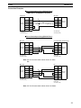
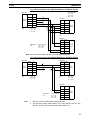
2-3-1 Control Connections . . . . . . . . . . . . . . . . . . . . . . . . . . . . . . . . . . . . .
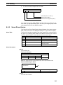
2-3-2 Serial Port Connections . . . . . . . . . . . . . . . . . . . . . . . . . . . . . . . . . .
2-3-3 DeviceNet Connection . . . . . . . . . . . . . . . . . . . . . . . . . . . . . . . . . . .
2-3-4 I/O Specifications . . . . . . . . . . . . . . . . . . . . . . . . . . . . . . . . . . . . . . .
2-3-5 Connection examples . . . . . . . . . . . . . . . . . . . . . . . . . . . . . . . . . . . .
Servo System Precautions . . . . . . . . . . . . . . . . . . . . . . . . . . . . . . . . . . . . . . . .
Wiring Precautions . . . . . . . . . . . . . . . . . . . . . . . . . . . . . . . . . . . . . . . . . . . . .
24
28
28
28
29
30
30
31
36
36
38
39
40
23
Section 2-1
Components and Unit Settings
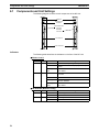
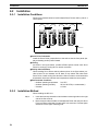
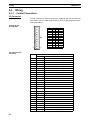
2-1
Components and Unit Settings
The following diagram shows the main components of the MC Unit.
MCW1 51
M CW15 1-DRT
STS
Indicators
RD
PORT0 ,1
SD
NS
RS-422A/485 Port
Connector
DeviceNet
Connector
2
1
I/O
25
STS
MS
RS-232C Ports
Connector
PORT2
1
RUN
PORT0 ,1
RUN
2
I/O
I/O Connector
26
25
+ 24V
26
+ 24V
Power Connector
0V
0V
Indicators
The following table describes the indicators on the front of the MC Unit.
■ Motion Control
Indicator
RUN
STS
Color
Green
Red
Status
Meaning
ON
The MC Unit is operating normally.
OFF
The MC Unit did not start properly or is not powered on.
Flashing with
STS
An error occurred in the communication with the
Servo Driver.
ON
The axis has been disabled. The Servo Enable
is not ON.
OFF
The axis is enabled.
Flashing alone A motion error has occurred. The Servo Driver
has been disabled.
Flashing with
RUN
An error occurred in the communication with the
Servo Driver.
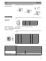
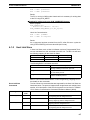
■ RS-422A/485 (MCW151-E only)
Indicator
SD
RD
24
Color
Green
Green
Status
Meaning
ON
Transmitting data.
OFF
No communication.
ON
Receiving data.
OFF
No communication.
Section 2-1
Components and Unit Settings
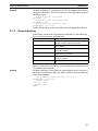
■ DeviceNet (MCW151-DRT-E only)
Indi Color
cator
MS
Green ON
Red
--NS
Status
---
Device
Operational
Meaning
Normal operating status.
Flashing Device in
Standby
Reading switch settings.
ON
Unit hardware error: Watchdog timer error.
Unrecoverable Fault
Flashing Minor Fault
Switch settings incorrect.
OFF
No Unit
Power
Unit power is not supplied, waiting for initial
processing to start, or the Unit is being reset.
Link OK.
Online, Connected.
Network is operating normally (communications established).
Green ON
Red
Definition
Flashing Online, Not
connected
Network is operating normally, but communications have not yet been established.
ON
A fatal communications error has occurred.
Network communications are not possible.
Critical Link
Failure
Flashing Connection
Timeout
Communications timeout.
OFF
Checking for node address duplication on the
Master, switch settings are incorrect, or fieldbus power is not supplied.
No Fieldbus
Power / Not
Online
Switch Settings
The MCW151 Units are equipped with the following DIP-switches.
■ DeviceNet Switch Settings (MCW151-DRT-E only)
The external switch settings will set the Slaves’ node address setting and
baud rate setting.
ON
ON
NA0
NA1
NA2
NA3
NA4
NA5
MD0
NC
DR0
DR1
1 2 3 4 5 6 7 8 9 10
1
2
3
4
5
6
7
8
9
10
Node address
The node address of the slave is set with pins 1 through 6 of the DIP switch.
Any node address within the setting range can be used as long as it is not
already set on another node.
25
Section 2-1
Components and Unit Settings
DIP switch setting
Pin 6
Pin 5
Pin 4
Pin 3
Node address
Pin 2
Pin 1
0
0
0
0
0
0
0 (default)
0
0
0
0
0
1
1
0
0
0
0
1
0
2
...
...
1
1
1
1
0
1
61
1
1
1
1
1
0
62
1
1
1
1
1
1
63
0: OFF, 1: ON
Baud rate
Pins 9 and 10 are used to set the baud rate as shown in the following table.
Pin 10
Note
Pin 9
Baud rate
OFF
OFF
125 kbps (default)
OFF
ON
250 kbps
ON
OFF
500 kbps
ON
ON
Not allowed
1. Always turn OFF the MC Unit’s power supply (including the communications power supply) before changing the baud rate setting.
2. Set the same baud rate on all of the nodes (master and slaves) in the Network.
Other settings
Pin 7 is used to select the I/O Slave Messaging mode. This determines the
allocation of the I/O Slave Messaging mode area.
Pin 7
I/O Slave Messaging Mode
OFF
Mode I (default)
ON
Mode II
Pin 8 is not used.
■ General Switch Settings (MCW151-E only)
ON
ON
SW1
SW2
SW3
SW4
SW5
SW6
SW7
SW8
SW9
SW10
1 2 3 4 5 6 7 8 9 10
1
2
3
4
5
6
7
8
9
10
For the MCW151-E the external DIP switch can be used for general purpose.
The value of the switch can be accessed using the SWITCH_STATUS parameter.
26
Section 2-1
Components and Unit Settings
DIP switch setting
Parameter
value
Pin
10
Pin
9
Pin
8
Pin
7
Pin
6
Pin
5
Pin
4
Pin
3
Pin
2
Pin
1
0
0
0
0
0
0
0
0
0
0
0 (default)
0
0
0
0
0
0
0
0
0
1
1
0
0
0
0
0
0
0
0
1
0
2
...
...
1
1
1
1
1
1
1
1
0
1
1021
1
1
1
1
1
1
1
1
1
0
1022
1
1
1
1
1
1
1
1
1
1
1023
0: OFF, 1: ON
■ Internal Switches
SW2
SW2
123 4
SW3
ON
ON
12 3 4
ON
123 4
SW3
ON
12 34
Switch SW2 (MCW151-E only)
Pin 1 and 2 select the serial communication for port 2.
Pin 2
Pin 1
Selection
OFF
OFF
RS-422A (default)
ON
ON
RS-485
Other not allowed
Pin 3 selects the termination resistor between receive pins (RD+ / RD -) for
port 2.
Pin 3
Selection
OFF
Termination disabled (default)
ON
Termination enabled
Pin 4 is not used.
Switch SW3
Pin 1 through 3 enable the termination resistor for the encoder channel A, B
and Z.
Pin 3
Pin 2
Pin 1
(channel Z) (channel B) (channel A)
Selection
OFF
Termination disabled for channel
(default)
ON
Termination enabled
Pin 4 is not used.
27
Section 2-2
Installation
2-2
2-2-1
Installation
Installation Conditions
Follow the procedure below to install multiple Servo Drivers side by side in a
control panel.
Fan
Fan
2
25
26
2-2-2
SD
1
2
25
26
I/O
30 mm min.
RUN
MCW151
STS
RD
RUN
S TS
SD
RD
PORT2
PORT2
PORT2
1
MCW151
STS
RD
PORT 0,1
SD
1
2
25
26
I/O
PORT2
RUN
PORT 0,1
MCW151
STS
RD
PORT 0,1
SD
PORT 0,1
MCW151
RUN
50 mm min.
1
2
25
26
I/O
I/O
+ 24V
+ 24V
+ 24V
+ 24V
0V
0V
0V
0V
10 mm min.
50 mm min.
■
Servo Driver Orientation
Install the Servo Driver perpendicular to the wall so that the front panel (display and setting section) faces forward.
■
Cooling
As shown in the figure above, provide sufficient space around each Servo
Driver for cooling by cooling fans or natural convection.
■
Side-by-side Installation
When installing Servo Drivers side-by-side as shown in the figure above, provide at least 10 mm between and at least 50 mm above and below each
Servo Driver. Install cooling fans above the Servo Drivers to avoid excessive
temperature rise and to maintain even temperature inside the control panel.
■
Environmental Conditions
• Ambient operating temperature:
• Ambient operating humidity:
• Vibration:
0 to 55°C
20% to 90% RH (no condensation)
4.9 m/s2
Installation Method
When installing the MC Unit
1,2,3...
28
1. Insert the lower two extensions into the bottom mounting holes on the right
side of the Servo Driver.
2. Move the upper side of the MC Unit towards the Driver and verify the Servo
Driver connector will directly fit into the MC Unit connector. Click the higher
extension into the upper mounting hole.
Section 2-2
Installation
RUN
M CW
SD
15 1
STS
PORT
2
PORT
0,
1
RD
1
2
I/O
25
26
+ 24
V
0V
When removing the MC Unit, press down the top of the MC Unit case and
remove the upper extension from the Driver.
Dimensions
The basic dimensions of the MC Unit are shown below.
MCW151
ON
STS
PORT0,1
RD
1
2
3
4
5
6
7
8
9
10
SW1
SW2
SW3
SW4
SW5
SW6
SW7
SW8
SW9
SW10
ON
SD
1 2 3 4 5 6 7 8 9 10
RUN
PORT2
2-2-3
1
2
I/O
25
26
+ 24V
0V
29
Section 2-3
Wiring
2-3
2-3-1
Wiring
Control Connections
I/O Connector
The I/O Connector is used for wiring to the digital I/O and the connection for
the encoder input or encoder output. Refer to 2-3-4 I/O Specifications for electrical specifications.
Connector pin
arrangement
1
2
A+
1
2
A-
B+
Z+
3
5
4
6
BZ-
0V_ENC
I0 / R0
7
9
8
10
5V_ENC
FG
I2
I4
11
13
12
14
I1 / R1
I3
I6
0V_IN
15
17
16
18
I5
I7
O8
O10
19
21
20
22
O9
O11
O12
0V_OP
23
25
24
26
O13
24V_OP
I/O
25
I/O Connector Pin
Functions
26
Pin
Signal
Name
1
30
A+
Function
Encoder phase A+ (Input / Output)
2
A-
Encoder phase A- (Input / Output)
3
B+
Encoder phase B+ (Input / Output)
4
B-
Encoder phase B- (Input / Output)
5
Z+
Encoder phase Z+ (Input / Output)
6
Z-
Encoder phase Z- (Input / Output)
7
0V_ENC
Encoder 0V common
8
5V_ENC
Encoder 5V power supply output
9
I0 / R0
(Registration) Input 0
10
FG
Frame Ground
11
I2
Input 2
12
I1 / R1
(Registration) Input 1
13
I4
Input 4
14
I3
Input 3
15
I6
Input 6
16
I5
Input 5
17
0V_IN
Inputs 0V common
18
I7
Input 7
19
O8
Output 8
20
O9
Output 9
21
O10
Output 10
22
O11
Output 11
23
O12
Output 12
24
O13
Output 13
25
0V_OP
Outputs 0V common
26
24V_OP
Outputs 24V power supply input
Section 2-3
Wiring
I/O Connector Type
Weidmüller B2L 3.5/26 SN SW (included in package)
Wiring Instructions
1
2
3
Power Connector
The Power Connector is used to connect the 24V power supply to the MC
Unit.
Connector pin
arrangement
Pin
+ 24V
0V
Power Connector Type
2-3-2
Name
1
+24 V
Function
Power Supply 24V
2
0V
Power Supply 0V
3
FG
Frame Ground
Phoenix MSTB 2.5/3-ST-5.08 (included in package)
Serial Port Connections
RS-232C Connections
The MC Unit has two serial RS-232C ports for communication with external
devices.
6 3
1
7 4
2
8 5
PORT0,1
Pin
Symbol
Name
Port
Direction
1
-
Not used
-
2
RS-1
Request to send
1
Output
3
SD-0
Send data
0
Output
4
SG-0
Signal ground
0
-
5
RD-0
Receive data
0
Input
6
SD-1
Send data
1
Output
7
SG-1
Signal ground
1
-
8
RD-1
Receive data
1
Input
RS-232C Interface Specifications
Item
Specifications
Electrical characteristics
Conform to EIA RS-232C
Synchronization
Start-stop synchronization (asynchronous)
Baud rate
1200 / 2400 / 4800 / 9600 / 19200 / 38400 bps
Transmission Format
Databit Length
7 or 8 bit
Stop Bit
1 or 2 bit
Parity Bit
Even/Odd/None
Transmission Mode
Point-to-point (1:1)
31
Section 2-3
Wiring
Item
Specifications
Transmission Protocol
Port 0
Motion Perfect Protocol
Port 1
Host Link Protocol (Master / Slave)
General-purpose
Galvanic Isolation
No
Connector type
8-pin miniDIN
Communication buffers
254 bytes (port 1)
Recommended Cables
R88A-CCM002P4
Programming Port 0 Connection Cable to Personal
Computer
R88A-CCM001P5-E
Splitter cable for serial ports 0 and 1
Cable length
15 m max.
RS-422A/485 Connection (MCW151-E only)
The MCW151-E has one serial RS-422A/485 port for communication with
external devices.
PORT2
Pin
Symbol
Name
Port
Direction
2
Input
Receive data (+)
2
Input
Frame Ground
2
-
1
RD-
Receive data (-)
2
RD+
3
FG
4
SD-
Send data (-)
2
Output
5
SD+
Send data (+)
2
Output
RS-422A/485 Interface Specifications (MCW151-E only)
Item
Specifications
Electrical characteristics
Conform to EIA RS-422A/485
Synchronization
Start-stop synchronization (asynchronous)
Baud rate
1200 / 2400 / 4800 / 9600 / 19200 / 38400 bps
Transmission Format
Databit Length
7 or 8 bit
Stop Bit
1 or 2 bit
Parity Bit
Even/Odd/None
Transmission Mode
Point-to-multipoint (1:N)
Transmission Protocol
RS-422A
Host Link Protocol (Master / Slave)
General Purpose
RS-485
General Purpose
Galvanic Isolation
Yes
Connector type
Phoenix MSTB 2.5/5-ST-5.08 (included in package).
Communication buffers
254 bytes
Flow control
None
Terminator
Yes, internal 220 Ω selectable by DIP-switch SW2
Cable length
500 m max.
32
Section 2-3
Wiring
Connection Examples
■ Direct Connections Using RS-232C Port 0
IBM PC/AT or Compatible Computers
Computer
MC Unit
Pin
Pin
RD
2
3
SD-0
SD
3
4
SG-0
GND
5
5
RD-0
RS
7
CS
8
FG
Shell
Signal
RS-232C
Interface
Signal
RS-232C
Interface
Shell FG
mini-DIN 8-pin
connector (male)
D-sub 9-pin
connector (male)
■ Direct Connections Using RS-232C Port 1
Programming Terminal (PT)
MC Unit
Programmable Terminal (PT)
Signal
RS-232C
Interface
Pin
Pin
RS-1
2
2
SD
SD-1
6
3
RD
SG-1
7
4
RS
8
5
CS
Shell
9
SG
RD-1
FG
mini-DIN 8-pin
connector (male)
Signal
RS-232C
Interface
D-sub 9-pin
connector (male)
Note MC Unit Communication Mode: Host Link Slave
PC
MC Unit
PC
Signal
RS-232C
Interface
Pin
Pin
RS-1
2
2
SD
SD-1
6
3
RD
SG-1
7
4
RS
RD-1
8
5
CS
9
SG
FG
mini-DIN 8-pin
connector (male)
Shell
Signal
RS-232C
Interface
Shell FG
D-sub 9-pin
connector (male)
Note MC Unit Communication Mode: Host Link Master
33
Section 2-3
Wiring
■ 1:N Connections Using RS-232C Port 1
Use the NT-AL001-E Converter Link Adapter
NT-AL001
MC Unit
General Device
Signal
RS-232C
Interface
Pin
Pin
RS-1
2
2
SD
SD-1
6
3
RD
Signal
Signal
RS-232C
Interface
FG
1
Frame ground
SG
2
Signal ground
SDB
3
Receive data (+)
SDA
4
Receive data (-)
5
Send data (+)
Send data (-)
SG-1
7
4
RS
RD-1
8
5
CS
Shell
6
+5V
RDB
9
SG
RDA
6
CSB
7
CSA
8
FG
mini-DIN 8-pin
connector (male)
RS-422A
Interface
MC Unit
Signal
Power
Supply
(5V)
D-sub 9-pin
connector (male)
+
Signal
Pin
RS-422A
Interface
Terminal Block
-
■ 1:1 Connections Using RS-422A/485 Port 2 (MCW151-E only)
Programming Terminal (PT)
MC Unit
Programmable Terminal (PT)
Signal
RS-422A
Interface
Pin
Signal
RD-
1
SDA
RD+
2
SDB
FG
3
-
SD-
4
RDA
SD+
5
RDB
COMBICON
Plug
RS-422A
Interface
Terminal Block
Note MC Unit Communication Mode: Host Link Slave
PC (Serial Communication Board)
PC
MC Unit
Pin
Pin
RD-
1
1
SDA
RD+
2
2
SDB
FG
3
SD-
4
6
RDA
SD+
5
8
RDB
Signal
RS-422A
Interface
COMBICON
Plug
Shell FG
D-sub 9-pin
connector (male)
Note MC Unit Communication Mode: Host Link Master
34
Signal
RS-422A
Interface
Section 2-3
Wiring
1:N, 4-wire Connections Using RS-422A/485 Port 2 (MCW151-E only)
MC Unit
Signal
RS-422A
Interface
DIP switch SW2
Pin 1 OFF
Pin 2 OFF
Pin 3 OFF
Pin
RD-
1
RD+
2
FG
3
SD-
4
1
RD-
SD+
5
2
RD+
DIP switch SW2
Pin 1 OFF
Pin 2 OFF
Pin 3 ON
3
FG
4
SD-
5
SD+
COMBICON
Plug
MC Unit
Pin
Signal
RS-422A
Interface
COMBICON
Plug
MC Unit
Pin
COMBICON
Plug
DIP switch SW2
Pin 1 OFF
Pin 2 OFF
Pin 3 ON
Signal
1
RD-
2
RD+
3
FG
4
SD-
5
SD+
RS-422A
Interface
Note MC Unit Communication Modes: Host Link Master and Slave
1:N, 2-wire Connections Using RS-422A/485 Port 2 (MCW151-E only)
MC Unit
MC Unit
Signal
RS-485
Interface
Pin
Pin
RD-
1
1
RD-
RD+
2
2
RD+
FG
3
3
FG
SD-
4
4
SD-
5
5
SD+
SD+
COMBICON
Plug
DIP switch SW2
Pin 1 ON
Pin 2 ON
Pin 3 ON
Signal
COMBICON
Plug
RS-485
Interface
DIP switch SW2
Pin 1 ON
Pin 2 ON
Pin 3 OFF
MC Unit
Pin
COMBICON
Plug
Note
DIP switch SW2
Pin 1 ON
Pin 2 ON
Pin 3 ON
Signal
1
RD-
2
RD+
3
FG
4
SD-
5
SD+
RS-485
Interface
1. MC Unit Communication Mode: General-purpose
2. For the 2-wire system (Switch SW2: pin 1,2 =ON), the RD- and SD- resp.
the RD+ and SD+ are interconnected within the MC Unit.
35
Section 2-3
Wiring
2-3-3
DeviceNet Connection
This section explains the pin allocation of the DeviceNet connector for the
DeviceNet network. For further details on how to connect the DeviceNet network, refer to DeviceNet Operation Manual (W267).
Pin
2-3-4
Symbol
Signal
Color of Cable
1
V+
Power line, positive voltage
Red
2
CAN-H
Communications line, high
White
3
Shield
Shield
4
CAN-L
Communications line, low
Blue
5
V-
Power line, negative voltage
Black
-
I/O Specifications
The following tables provide specifications and circuits for the I/O and
Encoder connections.
Digital Inputs
Digital inputs: I0 to I7
Item
Type
Specification
Circuit Configuration
PNP
Motion Control Unit
Maximum voltage
3.3kΩ
24 VDC + 10%
Input current
7.0 mA at 24 VDC
ON voltage
11 V min.
OFF voltage
1 V max.
I0/R0
9
External power
supply 24V
3.3Ω
0V_IN
17
0V common for input circuits
Input Response times
The response times given in the following table are the times between the
change in the input voltage and the corresponding change in the IN parameter.
These times are depending on the MC Unit’s Servo Period and the priority of
the corresponding BASIC task and they include the physical delays in the
input circuit.
Task Priority \ Servo Period
0.5 ms
1.0 ms
High Priority
1.8 ms (max.)
2.3 ms (max.)
Low Priority
2.8 ms (max.)
3.3 ms (max.)
Print Registration delay time
The print registration is used to capture position data in hardware triggered by
either a digital input or the Z-marker encoder signal. For the encoder axis 1
the print registration delay times are given by
36
Section 2-3
Wiring
Description
Delay Time
Digital Input I0/R0 and I1/R1 (rising edge)
50 µs
Digital Input I0/R0 and I1/R1 (falling edge)
150 µs
Z-marker (rising edge)
2 µs
Z-marker (falling edge)
2 µs
Digital Outputs
Digital outputs: O8 to O13
Item
Type
Specification
Circuit Configuration
PNP
Motion Control Unit
Maximum voltage
24 V + 10%
Protection
Over current, over
temperature and 2 A
fuse on common
2A Fuse
26
24V_OP
19
O8
25
0V_OP
Equivalent
circuit
External power
supply 24V
LOAD
100 mA each output
(600 mA total for
group of 6)
Internal Circuitry (galvanically
isolated from system)
Current capacity
To other output circuits
Output response times
The response times given in the following table are the times between a
change in the OP parameter and the corresponding change in the digital output circuit.
These times are mainly depending on the MC Unit’s Servo Period and they
include the physical delays in the output circuit.
Servo Period
Response time
0.5 ms
0.8 ms (max.)
1.0 ms
1.3 ms (max.)
Encoder Input
Item
Specification
Signal level
EIA RS-422A Standards
Input impedance
48 k Ω min.
Circuit Configuration
Motion Control Unit
A+
A-
Response frequency
1500 kp/s
B+
B-
Termination
Yes, 220 Ω selectable by switch
Z+
Z-
Galvanic isolation
No
1
2
3
4
5
6
+5V
Phase A axis 1
0V
+5V
Phase B axis 1
0V
+5V
Phase Z axis 1
0V
Line receiver
37
Section 2-3
Wiring
Encoder Output
Item
Specification
Signal level
Circuit Configuration
EIA RS-422A Standards
Motion Control Unit
A+
Maximum frequency
A-
500 kp/s
B+
B-
Galvanic isolation
No
Z+
Z-
2-3-5
1
+5V
Phase A axis 1
2
3
0V
+5V
Phase B axis 1
4
5
0V
+5V
Phase Z axis 1
6
0V
Line transmitter
Connection examples
Cascading encoder signal (MCW151 to MCW151)
MCW151 (output)
MCW151 (input)
A+
1
1
A+
A-
2
2
A-
B+
3
3
B+
B-
4
4
B-
Z+
5
5
Z+
Z-
6
6
Z-
0V_ENC
7
7
0V_ENC
5V_ENC
8
8
5V_ENC
FG
10
10
FG
Connecting master encoder input signal from W-series Servo Driver
W-series Servo Driver
38
MCW151 (input)
A+
33
1
A+
A-
34
2
A-
B+
36
3
B+
B-
35
4
B-
Z+
19
5
Z+
Z-
20
6
Z-
FG
Shell
7
0V_ENC
8
5V_ENC
10
FG
Section 2-4
Servo System Precautions
Connecting master external encoder signal
MCW151 (input)
Encoder
Black: Phase A+
1
A+
Black/red: Phase A-
2
A-
3
B+
4
B-
5
Z+
6
Z-
7
0V_ENC
8
5V_ENC
White: Phase B+
White/red: Phase BOrange: Phase Z+
Orange/red: Phase ZBlue: 0V (COM)
Line Driver output
Example: E6B2-CWZ1X
2-4
Brown: 5V DC
Servo System Precautions
The following precautions are directly related to the operation of the servo
system. Refer to 1-4-1 Servo System Principles for a description of servo system operation.
The direct connection of the MC Unit to the Servo Driver provides a safe interface without the risk of disconnected or faulty wiring. The interface provides
the MC Unit good monitoring operation to check the state of the Servo Driver
at any given time. The Servo Driver Alarms and Warnings can be quickly distinguished and appropriate action can be taken.
If the communications between the MC Unit and Servo Driver fail, this is
detected by either of the Units. The system will be halted into a fail-safe state.
For any details about the MC Unit and Servo Driver error handling and alarm
definitions, refer to SECTION 8 Troubleshooting.
Precautions for safe
operation
In a servo system employing a Servomotor, an unforeseen event may cause
the Servomotor to run out of control. Therefore, careful attention must be paid
to include sufficient safety measures into the system design.
To guarantee fail-safe operation for any circumstances or occurrences, the
following precautions must be taken.
Following Error Limit Setting
An important motion control safety precaution of the MC Unit is the following
error limit checking. When the Servomotor is controlled to follow a specific
demanded motion profile, this will always produce a following error between
the demanded and actual measured position.
The maximum allowable value for this following error can be set with the
FE_LIMIT axis parameter. When the following error at one moment exceeds
the limit, a Motion Error will occur. The Servo Driver will be disabled and all
motion will come to a halt. The user must be sure that this does not have an
adverse effect on the machine. Determine the value of following error limit
carefully according to the operating conditions of the application. See 6-3-74
FE_LIMIT for details.
External Limit Switches
The second safety precaution which is required is the use of limit switches.
Monitoring sensors are installed at the edges of the workpiece’s range of
movement to detect abnormal workpiece movement and stop operation if a
runaway occurs.
Although the limit switches can be connected either to the MC Unit as to the
Servo Driver, it is strongly recommended to connect the limit switches to the
39
Section 2-5
Wiring Precautions
Servo Driver. This will achieve a fast response of both the Servo Driver and
MC Unit.
For the Servo Driver, the limit switches should be connected to pins CN1-42
(FWD) and CN1-43 (REV). When using the MC Unit, the switches can be connected to any of the inputs. In both cases the axis parameters FWD_IN and
REV_IN for axis 0 are used to assign the limit switch inputs for the MC unit.
When the Servo Driver inputs are used, define FWD_IN=18 and REV_IN=19.
When the limits are connected to the Servo Driver and the correct settings are
set, the Driver will apply the dynamic brake to stop the Servomotor. Also the
appropriate bit of the AXISSTATUS axis parameter will be set.
2-5
Wiring Precautions
Electronically controlled equipment may malfunction because of noise generated by power supply lines or external loads. Such malfunctions are difficult to
reproduce, and determining the cause often requires a great deal of time. The
following precautions will aid in avoiding noise malfunctions and improving
system reliability.
• Use electrical wires and cables of the designated sizes as specified in the
operation manual for the Servo Driver. Use larger size cables for FG lines
of the Servo Driver and ground them over the shortest possible distances.
• Separate power cables (AC power supply lines and motor power supply
lines) from control cables (encoder lines and external input signal lines).
Do not group power cables and control cables together or place them in
the same conduit.
• Use shielded cables for control lines.
• Use the ready-made cables designed for MC Unit to reduce connectivity
problems.
• Connect a surge absorbing diode or surge absorber close to relays. Use a
surge-absorbing diode with a voltage tolerance of at least five times
greater than the circuit voltage.
AC relay
DC relay
+
DC
RY
Surge
absorbing
diode
AC
RY
Surge
absorber
Solenoid
SOL
Surge
absorber
• Noise may be generated on the power supply line if the same power supply line is used for an electric welder or electrical discharge unit. Connect
40
Section 2-5
Wiring Precautions
•
•
•
•
an insulating transformer and a line filter in the power supply section to
remove such noise.
Use twisted-pair cables for power supply lines. Use adequate grounds
(i.e., to 100 Ω or less) with wire cross sections of 1.25 mm2 or greater.
Use twisted-pair shielded cables for control voltage output signals, input
signals and encoder signals.
The maximum distance for the encoder signal from an encoder to the MC
Unit must not exceed 20 m.
The input terminals that operate the 24 V system are isolated with optical
couplers to reduce external noise effects on the control system.
41
SECTION 3
Motion Control Functions
This section describes the different Motion Control functions of the MC Unit. Also the functionality of the Servo Driver
related commands are explained.
3-1
3-2
3-3
Overview . . . . . . . . . . . . . . . . . . . . . . . . . . . . . . . . . . . . . . . . . . . . . . . . . . . . .
System Set-up . . . . . . . . . . . . . . . . . . . . . . . . . . . . . . . . . . . . . . . . . . . . . . . . .
System Functions . . . . . . . . . . . . . . . . . . . . . . . . . . . . . . . . . . . . . . . . . . . . . .
3-3-1 Servo Driver Control. . . . . . . . . . . . . . . . . . . . . . . . . . . . . . . . . . . . .
3-3-2 Digital I/O . . . . . . . . . . . . . . . . . . . . . . . . . . . . . . . . . . . . . . . . . . . . .
3-3-3 Monitoring Data . . . . . . . . . . . . . . . . . . . . . . . . . . . . . . . . . . . . . . . .
3-3-4 Absolute Encoder . . . . . . . . . . . . . . . . . . . . . . . . . . . . . . . . . . . . . . .
3-3-5 Other Servo Driver Commands . . . . . . . . . . . . . . . . . . . . . . . . . . . .
44
46
47
47
50
52
54
57
43
Section 3-1
Overview
3-1
Overview
The MC Unit together with the Servo Driver combine into one complete Servo
System which is able to control the application. All Motion Control commands
and data transfers are directly communicated between the MC Unit and the
Servo Driver.
MCW151
Servo Driver
RUN (Servo ON)
MING
TVSEL
Servo
Control
Alarm Reset
Axis 0: Servo
Axis 1: Enc In/ Out
Speed Reference
Torque Reference
Position Data
Axis 2: Virtual
Print Registration Data
Monitor Data
I/O Status Data
Digital Inputs
Control Status Data
Digital
I/O
Analog Input
Encoder
I/O
MC Axis Configuration
The MC Unit has 3 axes in total, which can be used for different motion control purposes depending on the application. The following table lists the different available axis types. The type of each axis is set by using the ATYPE axis
parameter.
Axis
number
0
1
2
Axis type
Servo
Virtual
Servo
Encoder input (default)
Encoder output
Virtual
ATYPE
value
13
0
2
3
14
0
■ Servo Axis
The servo axis for axis 0 controls the movement of the connected servo system. The Servomotor can be controlled in both speed control as in torque control.
Speed control can be achieved in closed loop and in open loop. In closed
loop, the speed reference to the Servo Driver based on the calculated
44
Section 3-1
Overview
(demanded) movement profile in the MC Unit and the actual (measured) position feedback from the Servomotor according to the control gain settings. In
open loop, a set speed reference value is outputted to the Servo Driver.
The torque control is achieved by outputting a set torque reference value to
the Driver. The axis is capable of switching between torque and speed control
during operation.
The servo axis for axis 1 can provide a second servo control loop to enable
dual feed-back control. More details can be found at the ADD_DAC command
description.
■ Encoder Input Axis
The encoder input axis provides an axis which counts the position data from a
connected pulse generator such as a Servo Driver or an external encoder.
The encoder input axis can be used for for measurement, registration and/or
synchronisation functions.
Item
Input pulse multiplication
Specification
x4
■ Encoder Output Axis
The encoder output axis provides a way of generating an encoder signal
which is cascaded to another device. The encoder signal is controlled by the
internal position of this axis.
All move commands and axis parameters available for the servo axis are
available.
Item
Specification
Output pulse ratio
64 : 1 (internal counts : output encoder pulses)
Z-marker period
4096 generated encoder edges
■ Virtual Axis
A virtual axis is used for computational purposes to create a move profile without physical movement on any actual Servo Driver.
The virtual axis behaves like a perfect servo axis (measured position is equal
to the demand position). All move commands and axis parameters available
for the servo axis are available.
Using the Parameter Unit
or Front Panel
Apart from the MC Unit there are three ways of accessing the Servo Driver:
• Using the Front Panel on the Servo Driver.
• Using the Hand-held Parameter Unit of the Servo Driver.
• Using Servo Driver Monitoring Software on the personal computer.
These three methods enables the user to perform parameter settings, speed
and current monitoring, I/O monitoring, autotuning, jogging and other operations.
■ Limitations on using Parameter Unit together with the MC Unit
If the MC Unit is mounted to the Servo Driver, it is not allowed to have the
Parameter Unit or the Servo Driver Software connected to the Servo Driver
when performing the following operations:
• During start-up of the system (either by power-up or software reset).
• During reading or writing Servo Driver parameters using commands
DRV_READ and DRV_WRITE.
• During execution of any Driver Command in the MC Unit such as
DRV_RESET and DRV_CLEAR.
■ Front Panel Display Area
The Front Panel Display Area of the Servo Driver will not be lit in the following
circumstances.
45
Section 3-2
System Set-up
• The Display will not be lit for some seconds during start-up (either by
power-up or software reset).
• The Display will not be lit for some time when the following commands are
executed in the MC Unit:
• Reading and writing Servo Driver parameters.
• Clearing the alarm status of the Servo Driver.
3-2
System Set-up
Servo Driver Settings
The Servo Driver is required to have the following settings. Refer to the
OMNUC W-series User’s manual (I531) for details.
Parameter No.
Pn000.1
Pn002.0
Pn002.1
Parameter Name
Required
Setting
Explanation
Control Mode
Selection
0
9
Torque / Speed Control
Torque command
input (during
speed control)
0
Not used
1
Use TREF as analog torque
limit input
Speed command
input (during
torque control)
0
Not used
1
Use (S)REF as analog speed
limit input
Remark
Speed Control
Pn003.0
Monitor 1
2
Torque Reference Monitor
Pn003.1
Monitor 2
0
Motor Speed Monitor
Pn50A.0
Input Signal Allocation Mode
1
User-defined
Pn50A.1
RUN Signal Input
Allocation
8
Always disabled
Switch is controlled by the MC
Unit.
Pn50A.2
MING Signal Input 8
Allocation
Always disabled
Switch is controlled by the MC
Unit.
Pn50A.3
POT Signal Input
Allocation
2
Assigned to CN1, pin 42 (valid
for low input)
8
Always disabled
3
Assigned to CN1, pin 43 (valid
for low input)
8
Always disabled
Pn50B.0
NOT Signal Input
Allocation
Pn50B.1
RESET Signal
Input Allocation
8
Always disabled
Switch is controlled by the MC
Unit.
Pn50C.3
TVSEL Signal
Input Allocation
8
Always disabled
Switch is controlled by the MC
Unit.
Pn511.0
-
8
Always disabled
Pn511.1
-
8
Always disabled
Pn511.2
-
8
Always disabled
Pn511.3
/EXT3 (Print Registration) Signal
Input Allocation
6
Assigned to CN1, pin 46 (valid Print registration on rising
for low input)
edge.
F
Assigned to CN1, pin 46 (valid Print registration on falling
for high input)
edge.
Servo Cycle Period
Setting
The MC Unit SERVO_PERIOD system parameter can be used to set the MC
Unit Servo Cycle and the Servo Driver communication access time. The following values are valid:
SERVO_PERIOD = 500 µs (default)
SERVO_PERIOD = 1000 µs
46
Section 3-3
System Functions
!Caution
3-3
When the parameter has been set, a power down or software reset (using
DRV_RESET) must be performed for the complete system. Not doing so may
result in undefined behaviour.
System Functions
This section explains all different functions of the MC Unit. The BASIC commands, functions and parameters can also be found in SECTION 6 BASIC
Motion Control Programming Language.
3-3-1
Servo Driver Control
Speed Control
The Speed Control mode is the main operation of the motion controller. The
speed control mode enables all different speed profiles determined by the
motion commands and possibly input encoder data. For an overview of the
available motion control commands which can be used, refer to 6-2-1 Motion
Control Commands.
For setting up a Motion Application with Speed Control, use one of the following settings in the Servo Driver.
Parameter No.
Parameter Name
Required
Setting
Explanation
Pn000.1
Control Mode
Selection
0
Speed Control
9
Torque / Speed Control
The following BASIC parameters need to be considered to set up the application in the MC Unit.
Parameter
Description
WDOG
The WDOG parameter is the software switch used to control the
Driver’s Servo ON input, which enables the driver.
SERVO
The SERVO parameter determines whether the base axis runs
under position control (ON) or open loop (OFF). When in open
loop the output speed reference voltage is determined by the
S_REF parameter.
S_REF
The S_REF parameter contains the speed reference value which
is applied to the Servo Driver when the base axis is in open loop.
P_GAIN
The P_GAIN parameter contains the proportional gain for the
axis.
I_GAIN
The I_GAIN parameter contains the integral gain for the axis.
D_GAIN
The D_GAIN parameter contains the derivative gain for the axis.
VFF_GAIN
The VFF_GAIN parameter contains the speed feed forward gain
for the axis.
OV_GAIN
The OV_GAIN parameter contains the output speed gain for the
axis.
47
Section 3-3
System Functions
■ Speed Reference
The Servomotor rotational speed is proportional to the speed reference value
resulting from either servo control or open loop (S_REF parameter). The
speed reference characteristics are given in the following graph.
Rotational
Speed [RPM]
Overspeed (+)
Rated speed (+)
S_RATE
1
Speed
reference
-15000
15000
Rated speed (-)
Overspeed (-)
The speed characteristics are Servomotor dependent. The S_RATE axis
parameter specifies the speed reference rate of the attached motor. This rate
is defined as the amount of Rotational speed (in RPM) per unit of speed reference.
Rotational Speed [RPM] = Speed Reference ⋅ S_RATE
■ Programming Example
In the following example a simple motion application including initiation for a
single axis is shown.
init:
BASE(0)
P_GAIN=.5: I_GAIN=0: D_GAIN=0
VFF_GAIN=0: OV_GAIN=0
ACCEL=1000
DECEL=1000
SPEED=500
WDOG=ON
SERVO=ON
loop:
MOVE(500)
WAIT IDLE
WA(250)
MOVE(-500)
WAIT IDLE
WA(250)
GOTO loop
■ Torque Limit Settings
During speed control, it is possible to limit the torque applied by the Servo
Driver by using the torque reference. The required Servo Driver setting is
Pn002.0=1 and refer to the Torque control section below for details on the
torque reference.
48
Section 3-3
System Functions
Torque Control
The Torque Control mode is used to apply a fixed torque, independent of the
travelling speed. This mode can be used for specific applications which
require a constant pressure.
To set up a Motion Application with Torque Control, the following setting in the
Servo Driver is required.
Parameter No.
Parameter Name
Required
Setting
Pn000.1
Control Mode
Selection
9
Explanation
Torque / Speed Control
The output no. 16 is used to control the switch between speed and torque
control during operation. Speed control will be applied when OP(16)=OFF,
and torque control will be enabled when OP(16)=ON. The torque control reference value is set by the T_REF axis parameter.
Speed
Control
Torque
Control
Speed
Control
Time
OP(16)
OFF
ON
OFF
■ Torque Reference
The torque applied to the Servomotor is proportional to the torque reference
value defined by the T_REF axis parameter. The torque reference characteristics are given in the following graph.
Applied Torque
[% of rated torque]
Max. torque (+)
T_RATE
Rated torque
(+ 100%)
1
Torque
reference
-15000
15000
Rated torque
(- 100%)
Max. torque (-)
The torque characteristics are Servomotor dependent. The actual applied
torque of the Servomotor as percentage of the rated torque can be determined by using the T_RATE axis parameter.
Applied Torque [% of rated torque] = T_REF ⋅ T_RATE
49
Section 3-3
System Functions
■ Speed Limit Settings
During torque control, it is advisable to limit the Servomotor speed by using
the speed reference. The required Servo Driver setting is Pn002.1=1 and
please refer to the Speed Control section above for details on the speed reference in open loop.
3-3-2
Digital I/O
The MC Unit has two different types of digital I/O. These are the digital I/O on
the MC Unit and the mapping of the Servo Driver digital I/O. The inputs and
outputs are accessible by using the IN and OP commands in BASIC.
Type
Input mapping
Description
Range (amount)
MC Unit Digital Inputs
0-7
Servo Driver Digital Inputs
16 - 22 (7)
Servo Driver Output Signals
24 - 31 (8)
Output mapping MC Unit Digital Outputs
8 - 13
Servo Driver Control Signals
(8)
(6)
16 - 17 (2)
Input Mapping
■ MC Unit Digital Inputs
The MC Unit inputs are freely allocable to different functions. Some of the
functions are origin search, limit switches, jog inputs and so on. The MC Unit
uses axis parameters to allocate a certain function to an input. The following
table introduces the related axis parameters.
Parameters
Description
DATUM_IN
Selection origin switch input
FAST_JOG
Selection of fast jog input
FHOLD_IN
Selection of feedhold input
FWD_IN
Selection of forward limit input
FWD_JOG
Selection of forward jog input
REV_IN
Selection of reverse limit input
REV_JOG
Selection of reverse jog input
■ Servo Driver Digital Inputs
The digital inputs of the Servo Driver (CN1-40 to CN1-46) can be directly
accessed from the MC Unit. The mapping of the inputs is specified in the following table.
Input
nr.
Servo Driver
Input
Description (according to required Servo Driver
settings)
16
CN1-40
General purpose 1
17
CN1-41
General purpose 2
18
CN1-42
Forward drive prohibit (POT) / General purpose 3
19
CN1-43
Reverse drive prohibit (NOT) / General purpose 4
20
CN1-44
General purpose 5
21
CN1-45
General purpose 6
22
CN1-46
Registration input / General purpose 7
■ Servo Driver Output Signals
The relevant Servo Driver output signals can be monitored in the MC Unit.
The mapping of the output signals is specified in the following table.
Input
nr.
50
Servo Driver
Signal
Description
24
ALM
Alarm output
25
WARN
Overload or regenerative overload warning output
Section 3-3
System Functions
Input
nr.
Print Registration
Servo Driver
Signal
Description
26
VCMP
Speed conformity output
27
TGON
Servomotor rotation detection output
28
READY
Servo ready output
29
CLIMT
Current limit detection output
30
VLIMT
Speed limit detection output
31
SVON
Servo ON complete
For both the Servo Driver axis 0 as the encoder input / output axis 1 the REGIST command can be used to perform print registration on the axis. Print registration captures an axis position as soon as a registration event occurs. The
registration event can be defined to be the moment when a registration input
or the Z-marker has been detected. Check the description of the REGIST
command for further details on print registration.
■ Print registration axis 0
Print registration on axis 0 is done by using the mechanism of the Servo
Driver. The registration can be triggered by either the Servomotor encoder Zmarker or by the CN1-46 input of the Servo Driver. When the input is used,
one of the following settings is required.
Parameter No.
Pn511.3
Parameter Name
Required
Setting
Explanation
Remark
/EXT3 (Print Registration) Signal
Input Allocation
6
Assigned to CN1, pin 46 (valid Print registration on rising
for low input)
edge.
F
Assigned to CN1, pin 46 (valid Print registration on falling
for low input)
edge.
■ Print registration axis 1
Print registration on axis 1 is done by using the MC Unit registration mechanism. The registration can be triggered by either the input I0/R0, input I1/R1 or
the encoder input Z-marker of the MC Unit.
Two registration registers are provided for the axis. This allows for two simultaneous registration events for which the difference in positions can be determined.
Driver Limit Switches
The limit switches should be connected to the Servo Driver. In this case both
the Servo Driver and the MC Unit are able to put the system into a safe state.
In order to use the Driver POT and NOT signals also in the MC Unit, the following settings are required:
FWD_IN=18 and
REV_IN=19
If one of the limits is reached, appropriate countermeasures will be performed.
See SECTION 8 Troubleshooting for details.
Output Mapping
■ MC Unit Digital Outputs
The physical outputs are freely allocable to any user defined functions. An
output can be set and reset depending on the current axis position by using
the command PSWITCH.
51
Section 3-3
System Functions
■ Servo Driver Control Signals
Two output signals are implemented as Servo Driver control signals. The control signals are the TVSEL and MING signals and they are specified as follows:
Output
nr.
16
Signal
Name
Description
States
TVSEL
Control Mode Switch
OFF: Speed control
ON: Torque control
17
MING
Gain reduction Input
OFF: Speed control by PI control
ON: Speed control by P control
3-3-3
Monitoring Data
The Servo Driver speed command (REF) analog input of the Servo Driver
provides the system an analog input which can be used for general purpose.
Furthermore, detailed Servo Driver speed and torque signals can be monitored in the MC Unit.
■ AIN0: Analog Input
The analog input is connected to CN1-5 and 6 and uses the Servo Driver
input circuit.
Servo
Driver
5
MCW151
ADC
6
Item
Specification
Input Voltage
Range: (-12 V, 12 V)
Resolution
16-bit over (- 15 V, 15 V)
26213
-12 V
12 V
-26214
52
Section 3-3
System Functions
■ AIN1: Torque Command Value
Analog input 1 contains the torque command data from the Servo Driver.
Item
Specification
Output Range
(-15000, 15000)
Resolution
Given by T_RATE axis parameter.
15000
-Max. torque
Max. torque
-15000
Torque command [% of rated torque] = AIN1*T_RATE
■ AIN2: Servomotor Rotation Speed
Analog input 2 contains the actual Servomotor Rotation Speed data from the
Servo Driver.
Item
Specification
Output Range
(-15000, 15000)
Resolution
Given by S_RATE axis parameter.
15000
-Overspeed
Overspeed
-15000
Rotation Speed [RPM] = AIN2*S_RATE
53
Section 3-3
System Functions
■ AIN3: Torque Monitor Value
Analog input 3 contains the Torque Monitor Value from the Servo Driver.
Item
Specification
Output Range
(-15000, 15000)
Resolution
Given by T_RATE axis parameter.
15000
-Max. torque
Max. torque
-15000
Torque Monitor [% of rated torque] = AIN3*T_RATE
3-3-4
Absolute Encoder
If the Servo Driver uses a Servomotor with an absolute encoder, the MC Unit
will obtain the absolute encoder position each start-up.
As a result, operation can be performed immediately without any origin search
operation at start-up. Use one of the following Servomotors with absolute
encoder.
Servo Driver
Servomotor Model
Encoder Resolution
Single-phase 100 V AC
R88M-W❏❏S-❏
16-bit
Single-phase 200 V AC
R88M-W❏❏T- ❏
16-bit
Three-phase 400 V AC
R88M-W❏❏C-❏
17-bit
A backup battery is required when using an absolute encoder. Install the battery into the Servo Driver’s battery holder.
Item
R88A-BAT01W
Specification
Absolute Encoder Backup Battery Unit
Battery: Toshiba ER3V, 3.6 V, 1000 mA
■ Setting up the encoder
Set-up the use of the absolute encoder by performing the following setting.
Parameter No.
Pn002.2
Parameter Name
Required
Setting
Operation switch
when using absolute encoder
0
Explanation
Use as absolute encoder
■ Multi-turn limit setting
If an absolute encoder is used, the counter counts the number of rotations
from the setup position and output the number of rotations from the Servo
Driver to the MC Unit. For some applications it is convenient to reset the multiturn data back to 0 after a certain amount of turns.
54
Section 3-3
System Functions
The multi-turn limit settings will set this amount of multi-turn rotations
Parameter No.
Pn205
Parameter Name
Setting
Range
Unit
Absolute encoder
0 - 65535
multi-turn limit setting
Rotation
Default
Setting
65535
Restart
Power?
Yes
With the default setting (Pn205=65535), the Servomotor multi-turn data will be
as follows:
Multi-turn data
+32767
0
Servomotor rotations
-32768
With any other setting than 65535, the Servomotor multi-turn data will be as
follows:
Multi-turn data
Pn205
0
Servomotor rotations
When the value is other than the default setting, the maximum value supported by the MC Unit is 32767.
Absolute Encoder Data
The absolute encoder position will be determined at start-up by retrieving the
following information
Variable
Description
M
Number of rotations
R
Resolution of the encoder
Pi
Incremental position within one rotation
Pe
Current position read by the encoder and
updated in MC Unit at start-up
Ps
Incremental position within one rotation read at
setup (to be determined by user)
Pm
Current position required for system
M=-1
M=0
M=1
M=2
M=3
M⋅R
Pi
Pm
-1
0
Ps
+1
+2
+3
Pe
+4
Position
55
Section 3-3
System Functions
At start-up the internal measured position of the MC Unit will be determined
by using the following formula.
P e = M ⋅ R + Pi
As the relevant position for the application is the current position read by the
encoder relative to the origin point determined at setup, the following operation needs to be applied.
P m = Pe – Ps
Absolute Encoder Setup
Procedure
Perform the setup operation for the absolute encoder in the following cases:
• When using the machine for the first time.
• When the backup alarm (A.81) is generated.
• When the Servo Driver’s power is turned OFF and the encoder cable is
removed.
The operation can be done by using the Parameter Unit, the front panel on
the Servo Driver, or using the personal computer monitoring software. Be
sure to follow the procedure carefully. Any mistakes in performing the procedure may lead to faulty operation.
■ Absolute Encoder Setup
At the setup of the application the incremental position of the origin P needs
s
to be determined. Perform the following actions:
• Set the correct Servo Driver settings. When the Servo Driver is set up for
absolute encoder, the MC Unit position will be automatically updated.
• Put the Servomotor into the origin position for the system.
• Execute the Servo Driver absolute encoder setup function (Fn008) to
reset the multi-turn data. Note that performing this operation will stop
communication between Servo Driver and MC Unit.
• Power down the system and put the power back on. The MC Unit measured position of axis 0 has now been set and is equal to the P s . The
measured position is represented by the MPOS axis parameter. The
value can be used in the start-up routine of the application.
Determining absolute
position
At every startup the measured position will be updated to the actual position
of the Servomotor. This position P e is the position as read by the encoder and
will need to be compensated for the origin point position P s . The application
initiation routine should contain the following steps.
• Define the current position relative to the origin point position. This possible by using the OFFPOS axis parameter or the DEFPOS command.
• During the parameter setting the UNITS axis parameter is used determining the unit conversion factor. The absolute position is modified accordingly.
Note The coordinate system of the MC Unit is not synchronized to the coordinate
system of the Servo Driver. The user must verify that the range of the Servomotor position falls into the MC Unit range. If not, the position will be adjusted
within range and the position data is invalid.
56
Section 3-3
System Functions
3-3-5
Other Servo Driver Commands
Access Servo Driver
Parameters
For applications which require online Servo Driver parameter changes or to
set-up a new Servo Driver, the MC Unit provides the BASIC commands
DRV_READ and DRV_WRITE. Using these commands it is possible to read
from and write to all Servo Driver parameters directly from the MC Unit user
program.
Reset Servo Driver and
MC Unit
The DRV_RESET command will software reset both the Servo Driver and the
MC Unit. This may be necessary for instance after a Servo Driver parameter
write using DRV_WRITE or for clearing a Servo Driver Alarm.
57
SECTION 4
Communication Interfaces
This section describes the communication components of the MCW151-E and MCW151-DRT-E. The functionality of the
serial communication protocols (including Host Link Master and Slave) and the DeviceNet interface are explained.
4-1
4-2
Serial Communications . . . . . . . . . . . . . . . . . . . . . . . . . . . . . . . . . . . . . . . . . .
4-1-1 Host Link Master . . . . . . . . . . . . . . . . . . . . . . . . . . . . . . . . . . . . . . .
4-1-2 Host Link Slave . . . . . . . . . . . . . . . . . . . . . . . . . . . . . . . . . . . . . . . .
4-1-3 General-purpose . . . . . . . . . . . . . . . . . . . . . . . . . . . . . . . . . . . . . . . .
DeviceNet (MCW151-DRT-E only) . . . . . . . . . . . . . . . . . . . . . . . . . . . . . . . .
4-2-1 Remote I/O Communications . . . . . . . . . . . . . . . . . . . . . . . . . . . . . .
4-2-2 Explicit DeviceNet Messages . . . . . . . . . . . . . . . . . . . . . . . . . . . . . .
60
60
65
67
68
68
72
59
Section 4-1
Serial Communications
4-1
Serial Communications
Both the MCW151-E as the MCW151-DRT-E provide serial ports for communication with host-computers, PCs, Programmable Terminals (PTs) and other
general-purpose devices. The MC Units are provided with the following protocols.
• Motion Perfect protocol:
For connection to personal computer
• Host Link:
For connection to PCs, Programmable Terminals, other MC Units
• General-purpose:
For connection to general-purpose external devices
MC Unit
MCW151-E
MCW151DRT-E
Serial Ports
Host Link Master
(note 3)
Host Link Slave
(note 3)
General Purpose
Port 0: RS-232C (See
note 1)
Yes
No
No
No
Port 1: RS-232C
No
Yes
Yes
Yes
Port 2: RS-422A/485
(See note 2)
No
Yes
Yes
Yes
Port 0: RS-232C (See
note 1)
Yes
No
No
No
Port 1: RS-232C
No
Yes
Yes
Yes
Personal Computer
PCs, MCW151s
Programmable
Terminals,
MCW151s
General-purpose
external devices
Devices to connect
Note
4-1-1
Motion Perfect
Protocol
1. The programming port 0 (RS-232C) can only be used for connection to a
personal computer with the Motion Perfect configuration software.
2. A 4-wire RS-422A connection must be used when using Host Link Communication.
3. For connection to a PC (Host Link Slave), configure the MC Unit as a Host
Link Master. For connection to a Programmable Terminal (Host Link Master), configure the MC Unit as a Host Link Slave. When using the Host Link
protocol to communicate between two (or more) MCW151, configure one
MC Unit as Host Link Master and the others as Host Link Slave.
Host Link Master
In Host Link Master mode, Host Link commands can be sent from the MC Unit
to a Host Link Slave such as a PC by using BASIC commands. The BASIC
task execution will be paused until the response has been received from the
other device. The following BASIC commands can be used:
BASIC Command
60
Description
SETCOM
SETCOM configures the serial communication port,
including enabling the Host Link protocols.
HLM_READ
HLM_READ reads data from the Host Link Slave to
either VR or Table memory.
HLM_WRITE
HLM_WRITE writes data to the Host Link Slave
from either VR or Table memory.
HLM_COMMAND
HLM_COMMAND executes a specific Host Link
command to the Slave.
HLM_STATUS
HLM_STATUS represents the status of the last
Host Link Master command.
HLM_TIMEOUT
HLM_TIMEOUT defines the Host Link Master timeout time.
Section 4-1
Serial Communications
Refer to SECTION 6 BASIC Motion Control Programming Language for further details on the commands.
Host Link Master
Commands
Type
I/O memory reading
I/O memory writing
The following Host Link commands are supported for Host Link Master. A full
description of the Host Link protocol can be found in SYSMAC CS/CJ Series
Communications Commands Reference Manual (W342).
Header
Code
Name
Function
RR
CIO AREA READ
Reads the specified number of words beginning with
the designated CIO/IR word.
RL
LR AREA READ
Reads the specified number of words beginning with
the designated LR word.
RH
HR AREA READ
Reads the specified number of words beginning with
the designated HR word.
RD
DM AREA READ
Reads the specified number of words beginning with
the designated DM word.
RJ
AR AREA READ
Reads the specified number of words beginning with
the designated AR word.
RE
EM AREA READ
Reads the specified number of words beginning with
the designated EM word.
WR
CIO AREA WRITE
Writes the specified data in word units beginning with
the designated CIO/IR word.
WL
LR AREA WRITE
Writes the specified data in word units beginning with
the designated LR word.
WH
HR AREA WRITE
Writes the specified data in word units beginning with
the designated HR word.
WD
DM AREA WRITE
Writes the specified data in word units beginning with
the designated DM word.
WJ
AR AREA WRITE
Writes the specified data in word units beginning with
the designated AR word.
WE
EM AREA WRITE
Writes the specified data in word units beginning with
the designated EM word.
CPU Unit status
SC
STATUS WRITE
Changes the CPU Unit’s operating mode.
Testing
TS
TEST
Returns, unaltered, a single block that was sent from
the Master
PC model code
reading
MM
PC MODEL READ
Reads the model code of the CPU Unit
Host Link communications processing
XZ
ABORT (command only)
Aborts the operation being performed by a Host Link
command, and returns to the initial status.
**
INITIALIZE (command only)
Initializes the transfer control procedures for all Host
Link Units.
IC
Undefined command
(response only)
This is the response when the command header code
is invalid.
The Host Link Master protocol supports the commands only in single frame
and can be used with the BASIC commands as shown in the next table. The
table also shows for which operating mode of a CPU Unit (Slave) the command is valid.
Header
Code
Name
BASIC Command
required
CPU Unit Operating Mode
RUN
MON
PRG
RR
CIO AREA READ
HLM_READ
Valid
Valid
Valid
RL
LR AREA READ
HLM_READ
Valid
Valid
Valid
RH
HR AREA READ
HLM_READ
Valid
Valid
Valid
RD
DM AREA READ
HLM_READ
Valid
Valid
Valid
RJ
AR AREA READ
HLM_READ
Valid
Valid
Valid
RE
EM AREA READ
HLM_READ
Valid
Valid
Valid
61
Section 4-1
Serial Communications
Header
Code
End Code Summary
End
code
Name
BASIC Command
required
CPU Unit Operating Mode
RUN
MON
PRG
WR
CIO AREA WRITE
HLM_WRITE
Not
Valid
Valid
Valid
WL
LR AREA WRITE
HLM_WRITE
Not
Valid
Valid
Valid
WH
HR AREA WRITE
HLM_WRITE
Not
Valid
Valid
Valid
WD
DM AREA WRITE
HLM_WRITE
Not
Valid
Valid
Valid
WJ
AR AREA WRITE
HLM_WRITE
Not
Valid
Valid
Valid
WE
EM AREA WRITE
HLM_WRITE
Not
Valid
Valid
Valid
SC
STATUS CHANGE
HLM_COMMAND
Valid
Valid
Valid
TS
TEST
HLM_COMMAND
Valid
Valid
Valid
MM
PC MODEL READ
HLM_COMMAND
Valid
Valid
Valid
XZ
ABORT (command
only)
HLM_COMMAND
Valid
Valid
Valid
**
INITIALIZE (command only)
HLM_COMMAND
Valid
Valid
Valid
IC
Undefined command (response
only)
-
Valid
Valid
Valid
These are the end codes as they can be defined in the HLM_STATUS parameter.
Contents
Probably cause
Corrective measures
00
Normal completion
No problem exists
---
01
Not executable in RUN mode
The command that was sent cannot
be executed when the PC is in RUN
mode.
Check the relation between the command and the PC mode.
13
FCS error
The FCS is wrong
Most likely influence from noise,
transfer the command again.
14
Format error
The command format is wrong, or a Check the format and transfer the
command that cannot be divided has command again.
been divided, or the frame length is
smaller than the minimum length for
the applicable command.
15
Entry number data error
The data is outside the specified
range or too long.
Correct the command arguments
and transfer the command again.
18
Frame length error
The maximum frame length of 131
bytes was exceeded.
Check the command and transfer
the command again.
19
Not executable
Access right was not obtained.
Obtain access rights.
21
Not executable due to CPU Unit
CPU error
The command cannot be executed
because a CPU error has occurred
in the CPU Unit.
Cycle the CPU Unit’s power supply.
Set-up Host Link Master
The SETCOM is required to set-up the serial communication port for the Host
Link Master protocol. After setting the following command:
SETCOM(baudrate,data_bits,stop_bits,parity,port,6)
the HLM_READ, HLM_WRITE and HLM_COMMAND commands can be
used to read and write data using Host Link.
62
Section 4-1
Serial Communications
Host Link Master Timeout
The timeout mechanism is implemented to avoid the BASIC task is paused for
a long time due to bad or no communication. The timeout time is specified by
the HLM_TIMEOUT parameter and is defined as the maximum amount of
time the program task will be paused to send the command and receive the
response.
Command
@
Characters
Response
....
*↵ @
....
*↵
Timeout
In case the total timeout time has elapsed, the correct status will be defined
using HLM_STATUS and the BASIC task will continue. The HLM_TIMEOUT
parameter specifies the timeout time for all commands and for all ports.
Host Link Master Status
In the process of sending a Host Link command and receiving a response
several problems may occur:
1. The Slave detects an error within the command and will send a corresponding end code indication.
2. The Slave cannot decode the command header code and sends a IC response.
3. The Master detects an error within the response. The corresponding end
code will be defined in the status.
4. The timeout time has elapsed for the Master.
The HLM_STATUS BASIC parameter represents the Host Link Master status
on the specific port.
HLM_STATUS status bits
9
8
7
0
End code (case 1 or case 3)
Timeout error (case 4)
Command not recognized (case 2)
If no error did occur the HLM_STATUS will have value 0. In case of a nonzero value, any appropriate action such as a re-try or emergency stop needs
to be programmed in the user BASIC program.
Programming
Precautions:
Consider the following precautions when programming the Host Link communications.
1. The Host Link Master commands are required to be executed from one
program task only to avoid any multi-task timing problems.
2. The Host Link Master commands provide the tools to exchange data with
the Host Link Slave. The user program should contain proper error handling routines to deal with communication failure and perform retries if necessary.
63
Section 4-1
Serial Communications
Examples:
Consider the following operations for a MC Unit connected to a PC using
port 2 (RS-422A). The Slave PC has node address 13.
■ Reading data from PC using HLM_READ
BASIC program:
‘ Set up Host Link Master for port 2
SETCOM(9600,7,2,2,2,6)
‘ Source address:
CIO/IR 002
‘ Amount of data:
2 words
‘ Destination address: VR(0)
HLM_READ(2,13,PLC_IR,2,2,MC_VR,0)
Host Link Communication:
HLM -> HLS: @13RR0002000242*
HLS -> HLM: @13RR000101010241*
Result:
VR address
value
0
257.0000
1
258.0000
■ Writing data to PC using HLM_WRITE
BASIC program:
‘ Source address:
Table(18)
‘ Amount of data:
2 words
‘ Destination address: LR 014
TABLE(18,$0701,$0702)
HLM_WRITE(2,13,PLC_LR,14,2,MC_TABLE,18)
Host Link Communication:
HLM -> HLS: @13WL0014070107025F*
HLS -> HLM: @13WL0059*
Result:
LR address
value
0
701 (Hex)
1
702 (Hex)
■ Send TS (test) command to PC using HLM_COMMAND
BASIC program:
HLM_COMMAND(HLM_TEST,2,13)
Host Link Communication:
HLM -> HLS: @13TSMCW151 TEST STRING2A*
HLS -> HLM: @13TSMCW151 TEST STRING2A*
Result:
HLM_STATUS PORT(2) = 0, which implies correct communication.
■ Set PC in MONITOR mode using HLM_COMMAND
BASIC program:
HLM_COMMAND(HLM_STWR,2,13,2)
Host Link Communication:
64
Section 4-1
Serial Communications
HLM -> HLS: @13SC0250*
HLS -> HLM: @13SC0052*
Result:
The PC is running in MON mode. Note that this is necessary for writing data
to the PC using HLM_WRITE.
■ Reading PC model code using HLM_COMMAND (timeout)
BASIC program:
HLM_TIMEOUT=500
‘ Destination address: VR(100)
HLM_COMMAND(HLM_MREAD,2,13,MC_VR,100)
Host Link Communication:
HLM -> HLS: @13MM42*
HLS -> HLM: no response
Result:
As no response has been received from the PC, after 500 servo cycles the
HLM_STATUS PORT(2) will have value 256 (bit 8 is set).
4-1-2
Host Link Slave
In Host Link Slave mode, a Host Link Master such as a Programmable Terminal can read data from and write data to the MC Unit. The MC Unit will have
the following mapping for the Host Link Slave.
MCW151 Memory
Host Link Mapping
Address Range
VR
CIO
0 to 250
Table
DM
0 to 7999
The following BASIC commands are used:
BASIC Command
Description
SETCOM
SETCOM configures the serial communication port,
including enabling the Host Link protocols.
HLS_NODE
HLS_NODE defines the Slave unit number for the
Host Link Slave protocol.
HLS_MODEL
HLS_MODEL defines the MC Unit model code for
the Host Link Slave protocol.
Refer to SECTION 6 BASIC Motion Control Programming Language for further details on the commands.
Host Link Slave
Commands
Type
I/O memory reading
I/O memory writing
The list of Host Link commands that are supported for the Host Link Slave are
listed here below. The protocol supports both single frame and multiple frame
transfer. A full description of the Host Link protocol can be found in SYSMAC
CS/CJ Series Communications Commands Reference Manual (W342).
Header
Code
Name
Function
RR
CIO AREA READ
Reads the specified number of words from VR memory beginning with the designated word.
RD
DM AREA READ
Reads the specified number of words from Table
memory beginning with the designated word.
WR
CIO AREA WRITE
Writes the specified data in word units to VR memory
beginning with the designated word.
WD
DM AREA WRITE
Writes the specified data in word units to Table memory beginning with the designated word.
65
Section 4-1
Serial Communications
Type
Header
Code
Name
Function
Testing
TS
TEST
Returns, unaltered, a single block that was sent from
the Master.
PC model code
reading
MM
PC MODEL READ
Reads the model code of the MC Unit as specified by
the HLS_MODEL parameter.
I/O memory area
registration and
reading
QQMR
REGISTER I/O MEMORY
Registers the I/O table with the contents of the actual
I/O configuration
QQIR
READ I/O MEMORY
Reads the registered I/O memory words/bits all at
once.
Host Link communications processing
XZ
ABORT (command only)
Aborts the operation being performed by a Host Link
command, and returns to the initial status.
**
INITIALIZE (command only)
Initializes the transfer control procedures for all Host
Link Units.
IC
Undefined command
(response only)
This is the response when the command header code
is invalid.
End Code Summary
End
code
These are the response end codes that can be returned in the response
frame.
Contents
Probably cause
Corrective measures
00
Normal completion
No problem exists
---
13
FCS error
The FCS is wrong
Check the FCS calculation method.
If there was influence from noise,
transfer the command again.
14
Format error
The command format is wrong, or a Check the format and transfer the
command that cannot be divided has command again.
been divided, or the frame length is
smaller than the minimum length for
the applicable command.
15
Entry number data error
The data is outside the specified
range or too long.
Correct the command arguments
and transfer the command again.
18
Frame length error
The maximum frame length of 131
bytes was exceeded.
Check the data and transfer the
command again.
19
Not executable
An I/O memory batch was executed
when items to read were not registered.
Register items to read before
attempting batch read.
A3
Aborted due to FCS error in transmission data
An FCS error occurred in the second Correct the command data and
or later frame.
transfer the command again.
A4
Aborted due to format error in trans- The command format did not match
mission data
the number of bytes in the second or
later frame.
A5
Aborted due to entry number data
error in transmission data
There was an entry number data
error in the second or later frame or
a data length error.
A8
Aborted due to frame length error in
transmission data
The length of the second or later
frames exceeded the maximum of
128 bytes.
Set-up Host Link Slave
The SETCOM is required to set-up the serial communication port for the Host
Link Slave protocol. After setting the following command:
SETCOM(baudrate,data_bits,stop_bits,parity,port,5)
the MC Unit will respond to any Host Link command from the master with the
specified node number as set with the HLS_NODE parameter.
66
Section 4-1
Serial Communications
Example:
4-1-3
Consider a MCW151-E connected to the NT11S Programmable Terminal
using port 2 (RS-422A). The Host Link Slave can be configured by using the
following program:
‘ Define Host Link Slave node
HLS_NODE = 15
‘ Define Host Link Slave model code
HLS_MODEL = $FA
‘ Set up Host Link Slave for port 2
SETCOM(9600,7,2,2,2,5)
The MC Unit is now set up to communicate with the Programmable Terminal.
General-purpose
The MCW151 provide a set of commands to implement any user-defined protocol. The list of commands is provided here.
BASIC Command
Description
SETCOM
SETCOM configures the serial communication port,
including enabling the Host Link protocols.
GET
GET assigns the ASCII code of a received character to a variable.
INPUT
INPUT will assign numerical input string values to
the specified variables.
KEY
KEY returns TRUE or FALSE depending on if a
character has been received.
LINPUT
LINPUT assigns the ASCII code of the characters to
an array of variables.
PRINT
PRINT outputs a series of characters to a serial
port.
Refer to SECTION 6 BASIC Motion Control Programming Language for further details on the commands.
Example:
Consider a MCW151-E connected to a general-purpose device using port 2
(RS-422A). The following problem will receive a series of data elements and
write it to VR variables:
‘ Set up General-purpose protocol for port 2
SETCOM(9600,7,2,2,2,0)
‘ Receive input
FOR i=0 to 99
INPUT#2, VR(i)
NEXT i
67
Section 4-2
DeviceNet (MCW151-DRT-E only)
4-2
DeviceNet (MCW151-DRT-E only)
The MCW151-DRT-E is connected to the DeviceNet network as a DeviceNet
Slave. This allows data from any area in the MC Unit to be read or written
from the Master. Through the DeviceNet, the MC Unit memory can be
accessed using one of the following two methods.
Accessing MC Unit
memory through remote
I/O areas
Remote I/O communication enables automatic exchange of I/O data between
the MC Unit and a PC with DeviceNet Master Unit without special programming in the PC. For the MC Unit, the input and output areas can each contain
up to 4 words.
Once the MC Unit’s memory input and output areas have been set, the MC
Unit memory can be read and written. The input area is regularly read by the
Master and the output is regularly written from the Master. This process maintains consistency between the Slave’s input and output areas and the input
and output areas allocated to the Master.
The data is transferred automatically at high speed so it is useful to use this
for data which requires regular data transfers with the Master.
Accessing MC Unit
memory with Explicit
Message Communications
When larger amount of data needs to be exchanged with the MC Unit, explicit
message communications can be used.
Transferring data with explicit message communications takes more time than
transferring data with the input and output areas, but all of the MC Unit memory can be accessed.
Use this feature for large data transfers which can be performed when
required, such as transferring position profile data.
Remote I/O
communications
Master Unit
CPU Unit
MC Unit
Input Area
Output Area
VR memory
Explicit message communications (Transfers
data in any area)
Table memory
DeviceNet Network
Refer to Appendix B Device Protocol (MCW151-DRT-E only) for the Device
Protocol definition.
4-2-1
Remote I/O Communications
The Master and Slaves can communicate as described below with DeviceNet
remote I/O communications.
• Input Area:
Inputs at the Slave are read automatically and mirrored in the Master’s
input area.
• Output Area:
Data written in the output area allocated in the Master’s memory are automatically output to the corresponding Slave.
68
Section 4-2
DeviceNet (MCW151-DRT-E only)
Note The names of the input and output areas indicate the direction of I/O from the
perspective of the Master.
Allocating Input and
Output Areas to the
Master
The MC Unit’s input and output areas are allocated to the Unit as a DeviceNet
Slave in the Master’s I/O memory.
■ Fixed Allocation
With fixed allocation, words in the CPU Unit are allocated in the order of node
numbers starting from node 00. The words are divided into an output area and
an input area. The specific words that are allocated depend on the model of
PC being used.
Each node address is allocated one input and one output word. If a Slave
requires more than one input or one output word, then it is assigned more
than one node address. If a Slave requires less than one word, it simply uses
the rightmost bits in the word allocated to it.
The MC Unit will occupy the number of words (number of node numbers) set
for the input and output areas using the external DIP switch pin 7.
Pin 7
Mode
Description
OFF
Mode I (default)
Input:
2 words
Output: 2 words
ON
Mode II
Input:
4 words
Output: 4 words
For example when the MC Unit has been selected to Mode II and the node
number is set to 5, the input area will occupy the words for nodes 5 through 8
and the output area will also occupy the words for nodes 5 through 8.
■ Free Allocation
A Configurator can be used to allocate a total of 4 blocks, blocks 1 and 2 in
the output area and input blocks 1 and 2 in the input area in any order.
Slaves and blocks can be allocated in any order. The number of words (number of bytes) that are used depends upon the addresses. The minimum is one
byte and the maximum is 64 bytes (32 words).
69
Section 4-2
DeviceNet (MCW151-DRT-E only)
Area Allocation
■ DeviceNet Input
The table below specifies the input data allocation of the status of the MC
Unit.
Input
word
1
Bit
00
Name
Unit Operating Flag
Function
1: MC Unit is operating.
0: MC Unit is not operating.
01
Servo Driver Enable Flag 1: Servo Driver enabled.
0: Servo Driver disabled.
02
Axis 0 Servo ON
1: Servo is ON for Servo Driver axis 0. The axis is in closed loop.
0: Servo is OFF for Servo Driver axis 0. The axis is in open loop.
03
MC Unit Motion Error
Flag
1: Motion error has occurred for one of the axes.
04
MC Unit Motion Warning
Flag
1: Motion warning has occurred for Servo Driver axis 0. The following
error warning limit is exceeded.
05
Servo Driver Alarm Flag
06
Servo Driver Warning
Flag
1: Servo Driver warning (WARN) has occurred.
07
Servo Driver Communication Error
1: Communication error between MC Unit and Servo Driver has
occurred.
08
Axis 0 Forward Limit Flag 1: Forward limit is set for Servo Driver axis 0.
0: No motion error.
0: No motion warning.
1: Servo Driver alarm (ALM) has occurred.
0: No Servo Driver alarm.
0: No Servo Driver warning.
0: No communication error.
0: No forward limit.
09
Axis 0 Reverse Limit Flag 1: Reverse limit is set for Servo Driver axis 0.
0: No reverse limit.
10
Axis 0 Datuming Flag
1: Datuming (origin search) in progress for Servo Driver axis 0.
0: No datuming.
11
Axis 0 Feedhold Flag
1: Feedhold input is set for Servo Driver axis 0.
12
Axis 0 Following Error
Limit Flag
1: Following error limit is reached for Servo Driver axis 0.
Task 1 Flag
1: Program is running on task no. 1.
0: No feedhold.
13
0: No following error limit.
0: No program is running on task.
14
Task 2 Flag
1: Program is running on task no. 2.
15
Task 3 Flag
1: Program is running on task no. 3.
2
00 to
15
User defined
Contents is allocated by using the FB_SET parameter.
3 (see
note)
00 to
15
User defined
Contents is set by VR(2).
4 (see
note)
00 to
15
User defined
Contents is set by VR(3).
0: No program is running on task.
0: No program is running on task.
Note The input words no. 3 and 4 will only be transferred when I/O Slave messaging mode II is selected.
70
Section 4-2
DeviceNet (MCW151-DRT-E only)
Input word 2
The allocation of input word 2 is determined by the FB_SET parameter. The
following settings are supported.
FB_SET
value
Bit
Name
0
00 to
15
1
MC Unit I/O Mapping
2
User defined
Function
Contents is set by VR(0)
00
(Registration) Input 0
1: Input is ON
01
(Registration) Input 1
1: Input is ON
0: Input is OFF
0: Input is OFF
02
Input 2
1: Input is ON
0: Input is OFF
03
Input 3
1: Input is ON
0: Input is OFF
04
Input 4
1: Input is ON
0: Input is OFF
05
Input 5
1: Input is ON
0: Input is OFF
06
Input 6
1: Input is ON
0: Input is OFF
07
Input 7
1: Input is ON
0: Input is OFF
08
Output 8
1: Output is ON
0: Output is OFF
09
Output 9
1: Output is ON
0: Output is OFF
10
Output 10
1: Output is ON
0: Output is OFF
11
Output 11
1: Output is ON
0: Output is OFF
12
Output 12
1: Output is ON
0: Output is OFF
13
Output 13
1: Output is ON
0: Output is OFF
14 to
15
Reserved
Servo Driver I/O Mapping
00
Input CN1-40
1: Input is ON
0: Input is OFF
01
Input CN1-41
1: Input is ON
0: Input is OFF
02
Input CN1-42
1: Input is ON
0: Input is OFF
03
Input CN1-43
1: Input is ON
0: Input is OFF
04
Input CN1-44
1: Input is ON
0: Input is OFF
05
Input CN1-45
1: Input is ON
0: Input is OFF
06
Input CN1-46
1: Input is ON
0: Input is OFF
07
Reserved
08
ALM
1: Servo Driver alarm occurred
0: No Servo Driver alarm
09
WARN
1: Servo Driver warning occurred
0: No Servo Driver warning
10
VCMP
11
TGON
12
READY
1: Speed match
0: No speed match
1: Servomotor rotating
0: Servomotor not rotating
1: Servo ready
0: Servo not ready
13
CLIMT
1: Torque limit
0: No torque limit
14
VLIMT
15
SVON
1: Speed limit
0: No speed limit
1: Servo ON complete
0: Servo ON not complete
71
Section 4-2
DeviceNet (MCW151-DRT-E only)
■ DeviceNet Output
The table below specifies the output data allocation of the status of the MC
Unit.
Output
word
Bit
Name
Function
1
00 to User defined
15
Contents is set at VR(1).
2
00 to User defined
15
Contents is set at VR(4).
3 (see
note)
00 to User defined
15
Contents is set at VR(5).
4 (see
note)
00 to User defined
15
Contents is set at VR(6).
Note The output words no. 3 and 4 will only be transferred when I/O Slave messaging mode II is selected.
4-2-2
Explicit DeviceNet Messages
Explicit DeviceNet messages (commands) can be sent from the Master to
write and read data to and from both the VR and Table memory of the MC
Unit.
This section presents the explicit messages supported by the MC Unit, and
provides usage examples. For further details on using explicit messages on
the Master Unit, refer to the Master Unit’s Operation Manual.
■ MC Unit Explicit Message List
Explicit message
Function
Page
Reads the specified MC Unit’s Table data. The data 75
TABLE DATA READ
(THREE-WORD FOR- is converted into three-word format.
MAT)
VR DATA READ
Reads the specified MC Unit’s VR data. The data is 76
(THREE-WORD FOR- converted into three-word format.
MAT)
VR DATA READ
(ONE-WORD FORMAT)
Reads the specified MC Unit’s VR data in words.
76
TABLE DATA WRITE Writes the specified MC Unit’s Table data. The data 77
(THREE-WORD FOR- is three-word format and will be converted into floatMAT)
ing point.
VR DATA WRITE
Writes the specified MC Unit’s VR data. The data is 78
(THREE-WORD FOR- three-word format and will be converted into floatMAT)
ing point.
VR DATA WRITE
(ONE-WORD FORMAT)
Writes the specified MC Unit’s VR data in words.
79
RESET
Will perform a software reset of both the MC Unit
and the Servo Driver.
80
■ Data Formats
The MC Unit explicit messaging supports two data format types.
One-word format
72
The data is transferred word by word from each PC memory location to each
variable in the MC unit and vice versa. The value in the MC Unit is always the
integer equivalent of the hexadecimal value in the PC (no 2's complement).
From the floating-point data in the MC unit only the integer part will be transferred. The valid range is [0,65535].
Section 4-2
DeviceNet (MCW151-DRT-E only)
Three-word format
The data in the PC is represented by three memory elements, in total three
words. The following is the configuration of a BCD position data item.
j+0
0
0
0
A
j+1
x103
x102
x101
x100
j+2
x107
x106
x105
x104
3
2
s
1
0
Decimal point A = 0 (Indicates 1)
1 (Indicates 0.1)
2 (Indicates 0.01)
Position data
3 (Indicates 0.001)
4 (Indicates 0.0001)
bit
x107
Sign bit (s)
0: positive
1: negative
Example 1: The three-word format of value 56143 is given by
j+0
0
0
0
0
j+1
6
1
4
3
j+2
0
0
0
5
Example 2: The three-word format of value -48.89 is given by
j+0
0
0
0
2
j+1
4
8
8
9
j+2
8
0
0
0
One data item uses three words. Therefore the total words for data transfers
should be the amount of data transferred multiplied by three.
4-2-2-1
Message Communications
When sending explicit messages from an OMRON Master Unit, use the
CMND or IOWR instruction to send the message data as an EXPLICIT MESSAGE SEND (28 01) FINS command.
Command Block
28
01
32
00
8A
Command
Class ID
code
Service code
Destination node address
Response Block
00
01
Instance ID
242 bytes max.
Service Data
Normal Response
28
01
Command
code
00
00
240 bytes max.
Response No. of bytes
code
received
Service Data
Service code
Source node address
Note For a normal response, the leftmost bit of the service code specified in the
command will be turned ON and then returned. For example, a command
service code of 32 Hex is returned as B2 Hex in the response.
73
Section 4-2
DeviceNet (MCW151-DRT-E only)
Error Response
The following response is returned if an error occurs for the explicit message.
28
01
Command
code
Parameters
00
00
94
FF
Response No. of bytes
code
received
Additional error code FF Hex
General error code
Service code 94 Hex
Source node address
Destination node address (command)
The node address of the destination of the explicit message.
Service code (command, response)
A service code defined for DeviceNet. In a normal response, bit 15 of the service code specified will be turned ON and returned. For an error response, the
service code will always be 94 Hex.
Class ID (command)
The class ID of the destination of the explicit message. The class ID is always
008A Hex when reading or writing the MC Unit memory.
Instance ID (command)
The instance ID of the destination of the explicit message. The instance ID is
always 0001 Hex when reading or writing the MC Unit memory.
Service data (command, response)
The data defined for the services codes.
No. of bytes received (response)
The number of bytes received from the destination node address (local node).
Source node address (response)
The node address of the OMRON I/O Slave Unit or slave manufactured by
another company of which the explicit message was sent is returned.
General error code (response)
The following error codes may be returned.
General
error code
74
Error name
Cause of error
08 Hex
Service not supported
The requested service was not implemented or was not defined for this
Object Class/Instance.
09 Hex
Invalid attribute value
Invalid attribute data detected.
11 Hex
Reply data too large
The data to be transmitted in the
response buffer is larger than the allocated response buffer.
13 Hex
Not enough data
The service did not supply enough
data to perform the specified operation.
15 Hex
Too much data
The service supplied more data than
was expected.
16 Hex
Object does not exist
The object does not exist in the
device.
20 Hex
Invalid parameter
A parameter associated with the
request was invalid.
Section 4-2
DeviceNet (MCW151-DRT-E only)
Note
4-2-2-2
1. Unlike other FINS commands, this command is addressed to the local
node’s DeviceNet Master Unit. The actual destination of the explicit message is given in the command data, as described above.
Always specify the local node’s DeviceNet Master Unit in the control code
of the CMND or IOWR instruction. An error will occur if another node’s
Master Unit is specified.
2. If the DeviceNet Master Unit receives an explicit message, it will automatically return a response.
Explicit Messages
TABLE DATA READ
(THREE-WORD FORMAT)
TABLE DATA READ (THREE-WORD FORMAT) will read Table data. The
data will be converted in three-word format.
Command Block
28
01
32
00
8A
Command
Class ID
code
Service code
Destination node address
00
01
Instance ID
Length L
Address H Length H
Address L
Response Block
28
01
Command
code
00
00
B2
..
Word data L
Word data H
Service code
Source node address
Response No. of bytes
code
received
Read data
(Maximum 240 bytes)
Parameters
Service code (command, response)
In the command, 32 Hex is specified. In the response, the leftmost bit is
turned ON and B2 Hex is returned.
Address H, Address L (command)
The address in hexadecimal of the first word of data to be read.
Address H: Leftmost 2 digits of the address in 4-digit hexadecimal.
Address L: Rightmost 2 digits of the address in 4-digit hexadecimal.
For the Table memory, the maximum value is 7999 (1F3F Hex).
Length H, Length L (command)
The number of Table memory elements to read.
Length H: Leftmost 2 digits of the length in 4-digit hexadecimal (ignored for
MC Unit).
Length L: Rightmost 2 digits of the length in 4-digit hexadecimal.
When an OMRON Master is being used, the maximum is 39 elements (27
Hex). The 39 Table elements imply 234 bytes to be transferred.
Read data (response)
The specified data is returned from word H (leftmost byte: bits 08 to 15) to
word L (rightmost byte: bits 00 to 07).
Note The user should be aware that the MC Unit does not check if the MC Unit
memory data is within range of the three-word format.
75
Section 4-2
DeviceNet (MCW151-DRT-E only)
VR DATA READ (THREEWORD FORMAT)
VR DATA READ (THREE-WORD FORMAT) will read VR data. The data will
be converted in three-word format.
Command Block
28
01
33
00
8A
Command
Class ID
code
Service code
Destination node address
00
01
Instance ID
Length L
Address H Length H
Address L
Response Block
28
01
Command
code
00
00
B3
..
Word data L
Word data H
Service code
Source node address
Response No. of bytes
code
received
Read data
(Maximum 240 bytes)
Parameters
Service code (command, response)
In the command, 33 Hex is specified. In the response, the leftmost bit is
turned ON and B3 Hex is returned.
Address H, Address L (command)
The address in hexadecimal of the first word of data to be read.
Address H: Leftmost 2 digits of the address in 4-digit hexadecimal (ignored
for MC Unit).
Address L: Rightmost 2 digits of the address in 4-digit hexadecimal.
For the VR memory, the maximum value is 250 (FA Hex).
Length H, Length L (command)
The number of VR memory elements to read.
Length H: Leftmost 2 digits of the length in 4-digit hexadecimal (ignored for
MC Unit).
Length L: Rightmost 2 digits of the length in 4-digit hexadecimal.
When an OMRON Master is being used, the maximum is 39 elements (27
Hex). The 39 VR elements imply 234 bytes to be transferred.
Read data (response)
The specified data is returned from word H (leftmost byte: bits 08 to 15) to
word L (rightmost byte: bits 00 to 07).
Note The user should be aware that the MC Unit does not check if the MC Unit
memory data is within range of the three-word format.
VR DATA READ (ONEWORD FORMAT)
76
VR DATA READ (ONE-WORD FORMAT) will read VR data. The data will be
converted in one-word format.
Section 4-2
DeviceNet (MCW151-DRT-E only)
Command Block
28
01
34
00
8A
Command
Class ID
code
Service code
Destination node address
00
01
Instance ID
Length L
Address H Length H
Address L
Response Block
28
01
Command
code
00
00
B4
..
Word data L
Word data H
Service code
Source node address
Response No. of bytes
code
received
Read data
(Maximum 240 bytes)
Parameters
Service code (command, response)
In the command, 34 Hex is specified. In the response, the leftmost bit is
turned ON and B4 Hex is returned.
Address H, Address L (command)
The address in hexadecimal of the first word of data to be read.
Address H: Leftmost 2 digits of the address in 4-digit hexadecimal (ignored
for MC Unit).
Address L: Rightmost 2 digits of the address in 4-digit hexadecimal.
For the VR memory, the maximum value is 250 (FA Hex).
Length H, Length L (command)
The number of VR memory elements to read.
Length H: Leftmost 2 digits of the length in 4-digit hexadecimal (ignored for
MC Unit).
Length L: Rightmost 2 digits of the length in 4-digit hexadecimal.
When an OMRON Master is being used, the maximum is 119 elements (77
Hex). The 119 VR elements imply 238 bytes to be transferred.
Read data (response)
The specified data is returned from word H (leftmost byte: bits 08 to 15) to
word L (rightmost byte: bits 00 to 07).
TABLE DATA WRITE
(THREE-WORD FORMAT)
TABLE DATA WRITE (THREE-WORD FORMAT) will write Table data. The
Table data will be defined according to the three-word format.
Command Block
28
01
35
00
8A
Command
Class ID
code
Service code
Destination node address
00
01
..
Instance ID
Word data L
Word data H
Address H Length H
Length L
Address L
Write data
(Max. 238 bytes)
77
Section 4-2
DeviceNet (MCW151-DRT-E only)
Response Block
28
01
Command
code
00
00
00
02
B5
Response No. of bytes
code
received
Service code
Source node address
Parameters
Service code (command, response)
In the command, 35 Hex is specified. In the response, the leftmost bit is
turned ON and B5 Hex is returned.
Address H, Address L (command)
The address in hexadecimal of the first word of data to be read.
Address H: Leftmost 2 digits of the address in 4-digit hexadecimal.
Address L: Rightmost 2 digits of the address in 4-digit hexadecimal.
For the Table memory, the maximum value is 7999 (1F3F Hex).
Length H, Length L (command)
The number of Table memory elements to write.
Length H: Leftmost 2 digits of the length in 4-digit hexadecimal (ignored for
MC Unit).
Length L: Rightmost 2 digits of the length in 4-digit hexadecimal.
When an OMRON Master is being used, the maximum is 39 elements (27
Hex). The 39 Table elements imply 234 bytes to be transferred.
Write data (command)
The specified data should be written from word H (leftmost byte: bits 08 to 15)
to word L (rightmost byte: bits 00 to 07).
Note The user should be aware that the MC Unit does not check if the PC memory
data complies to the three-word format.
VR DATA WRITE (THREEWORD FORMAT)
VR DATA WRITE (THREE-WORD FORMAT) will write VR data. The VR data
will be defined according to the three-word format.
Command Block
28
01
36
00
8A
Command
Class ID
code
Service code
Destination node address
00
01
..
Instance ID
Word data L
Address H Length H
Word data H
Address L
Length L
Write data
(Max. 238 bytes)
78
Section 4-2
DeviceNet (MCW151-DRT-E only)
Response Block
28
01
Command
code
00
00
00
02
B6
Response No. of bytes
code
received
Service code
Source node address
Parameters
Service code (command, response)
In the command, 36 Hex is specified. In the response, the leftmost bit is
turned ON and B6 Hex is returned.
Address H, Address L (command)
The address in hexadecimal of the first word of data to be read.
Address H: Leftmost 2 digits of the address in 4-digit hexadecimal (ignored
for MC Unit).
Address L: Rightmost 2 digits of the address in 4-digit hexadecimal.
For the VR memory, the maximum value is 250 (FA Hex).
Length H, Length L (command)
The number of VR memory elements to read.
Length H: Leftmost 2 digits of the length in 4-digit hexadecimal (ignored for
MC Unit).
Length L: Rightmost 2 digits of the length in 4-digit hexadecimal.
When an OMRON Master is being used, the maximum is 39 elements (27
Hex). The 39 VR elements imply 234 bytes to be transferred.
Write data (command)
The specified data should be written from word H (leftmost byte: bits 08 to 15)
to word L (rightmost byte: bits 00 to 07).
Note The user should be aware that the MC Unit does not check if the PC memory
data complies to the three-word format.
VR DATA WRITE (ONEWORD FORMAT)
VR DATA WRITE (ONE-WORD FORMAT) will write VR data. The VR data
will be defined according to the one-word format.
Command Block
28
01
37
00
8A
Command
Class ID
code
Service code
Destination node address
00
01
..
Instance ID
Word data L
Address H Length H
Word data H
Address L
Length L
Write data
(Max. 238 bytes)
79
Section 4-2
DeviceNet (MCW151-DRT-E only)
Response Block
28
01
Command
code
00
00
00
02
B7
Response No. of bytes
code
received
Service code
Source node address
Parameters
Service code (command, response)
In the command, 37 Hex is specified. In the response, the leftmost bit is
turned ON and B7 Hex is returned.
Address H, Address L (command)
The address in hexadecimal of the first word of data to be read.
Address H: Leftmost 2 digits of the address in 4-digit hexadecimal (ignored
for MC Unit).
Address L: Rightmost 2 digits of the address in 4-digit hexadecimal.
For the VR memory, the maximum value is 250 (FA Hex).
Length H, Length L (command)
The number of VR memory elements to write.
Length H: Leftmost 2 digits of the length in 4-digit hexadecimal (ignored for
MC Unit).
Length L: Rightmost 2 digits of the length in 4-digit hexadecimal.
When an OMRON Master is being used, the maximum is 119 elements (77
Hex). The 119 VR elements imply 238 bytes to be transferred.
Write data (command)
The specified data should be written from word H (leftmost byte: bits 08 to 15)
to word L (rightmost byte: bits 00 to 07).
RESET
RESET will perform a software reset of both the MC Unit and the Servo Driver
(as DRV_RESET command).
Command Block
28
01
05
00
8A
Class ID
Command
code
Service code
Destination node address
00
01
Instance ID
Address H
Response Block
28
01
Command
code
00
00
00
02
85
Response No. of bytes
code
received
Service code
Source node address
80
Section 4-2
DeviceNet (MCW151-DRT-E only)
Parameters
Service code (command, response)
In the command, 05 Hex is specified. In the response, the leftmost bit is
turned ON and 85 Hex is returned.
4-2-2-3
Sample Programs
Using the CMD(490)
instruction to read data
In the following example, the CMD(490) instruction is used to read data (oneword format) from VR(200) to VR(203) (4 words) on the Slave Unit, and store
them to the Master (CS1 PCs) from D02000 onwards. For more information
on explicit messages, refer to the DeviceNet Master Unit Operation Manual or
for information on the CMD(490) instruction, refer to the PCs Operation Manual.
Example Conditions
Master node address: 0
Slave network address: 1
Slave node address:
2
Example: Using CMD(490)
CMD
S
D
C
Command Words (S: First Command word)
Word
Contents (Hex)
Meaning
S
28 01
EXPLICIT MESSAGE SEND command
code: 28 01 Hex
S+1
02 34
Slave node address: 2
VR DATA READ (ONE-WORD FORMAT)
command service code: 34 Hex
S+2
00 8A
Class ID: 008A Hex
S+3
00 01
Instance ID: 0001 Hex
S+4
00 C8
Read start address VR(200): 00C8 Hex
S+5
00 04
Number of Table elements to write: 0004
Hex
D: Response Words (D: First Response Word)
Results are stored as shown in the following table.
Word
Contents (Hex)
Meaning
D
28 01
EXPLICIT MESSAGE SEND command
code: 28 01 Hex
D+1
00 00
Response code (0000 Hex: Normal completion)
D+2
00 0A
No. of received bytes (data length after
D02003): 10 bytes
D+3
02 B4
Slave node address: 2
VR DATA READ (ONE-WORD FORMAT)
response service code: B4 Hex
D+4
00 0F
Data read from the MC Unit’s VR(200).
One-word format: 15
D+5
00 BF
Data read from the MC Unit’s VR(201).
One-word format: 191
81
Section 4-2
DeviceNet (MCW151-DRT-E only)
Word
Contents (Hex)
Meaning
D+6
0A 33
Data read from the MC Unit’s VR(202).
One-word format: 2611
D+7
FF FF
Data read from the MC Unit’s VR(203).
One-word format: 65535
Control Words (C: First Control Word)
Word
Using the CMD(490)
instruction to write data
Contents (Hex)
Meaning
C
00 0C
No. of bytes of command data: 12 bytes of
command data, S
C+1
00 10
No. of bytes of response data: 16 bytes of
response data, D
C+2
00 01
Destination node network address: 1
C+3
00 FE
Master’s node address: 0
Master’s Unit address: FE Hex
C+4
00 00
Response returned, communication port
No.: 0, No. of retries: 0
C+5
00 64
Response monitoring time: 10 s
In the following example, the CMD(490) instruction is used to write data (three
word format) to Table(10) to Table(12) on the Slave Unit, from the Master
(CS1 PCs). For more information on explicit messages, refer to the DeviceNet
Master Unit Operation Manual or for information on the CMD(490) instruction,
refer to the PCs Operation Manual.
Example Conditions
Master node address: 0
Slave network address: 1
Slave node address:
2
Example: Using CMND(490)
CMND
S
D
C
Command Words (S: First Command Word)
Word
82
Contents (Hex)
Meaning
S
28 01
EXPLICIT MESSAGE SEND command
code: 28 01 Hex
S+1
02 35
Slave node address: 2
TABLE DATA WRITE (THREE-WORD
FORMAT) command service code: 35
Hex
S+2
00 8A
Class ID: 008A Hex
S+3
00 01
Instance ID: 0001 Hex
S+4
00 0A
Write start address Table(10): 000A Hex
S+5
00 03
Number of Table elements to write: 0003
Hex
S+6
00 00
S+7
92 78
Data written to the MC Unit’s Table(10).
Three word format: 279278
S+8
00 27
Section 4-2
DeviceNet (MCW151-DRT-E only)
Word
Contents (Hex)
S+9
00 01
S+10
42 86
S+11
80 01
S+12
00 00
S+13
88 24
S+14
00 92
Meaning
Data written to the MC Unit’s Table(11).
Three word format: -1428.6
Data written to the MC Unit’s Table(12).
Three word format: 928824
D: Response Words (D: First Response Word)
Results are stored as shown in the following table.
Word
Contents (Hex)
Meaning
D
28 01
EXPLICIT MESSAGE SEND command
code: 28 01 Hex
D+1
00 00
Response code (0000 Hex: Normal completion)
D+2
00 02
No. of received bytes (data length after
D02003): 2 bytes
D+3
02 B5
Slave node address: 2
TABLE DATA WRITE (THREE-WORD
FORMAT) response service code: B5 Hex
Control Words (C: First Control Word)
Word
Contents (Hex)
Meaning
C
00 1E
No. of bytes of command data: 30 bytes of
command data, S
C+1
00 08
No. of words of response data: 8 bytes of
response data, D
C+2
00 01
Destination node network address: 1
C+3
00 FE
Master’s node address: 0
Master’s Unit address: FE Hex
C+4
00 00
Response returned, communications port
No.: 0, No. of retries: 0
C+5
00 64
Response monitoring time: 10 s
83
SECTION 5
Multitasking BASIC Programming
This section provides an overview of the fundamentals of multitasking BASIC programs and the methods by which
programs are managed in the MC Unit.
5-1
5-2
5-3
5-4
5-5
5-6
5-7
Overview . . . . . . . . . . . . . . . . . . . . . . . . . . . . . . . . . . . . . . . . . . . . . . . . . . . . .
BASIC Programming . . . . . . . . . . . . . . . . . . . . . . . . . . . . . . . . . . . . . . . . . . .
5-2-1 Axis, System and Task Statements . . . . . . . . . . . . . . . . . . . . . . . . . .
5-2-2 Data Structures and Variables . . . . . . . . . . . . . . . . . . . . . . . . . . . . . .
5-2-3 Mathematical Specifications. . . . . . . . . . . . . . . . . . . . . . . . . . . . . . .
Motion Execution . . . . . . . . . . . . . . . . . . . . . . . . . . . . . . . . . . . . . . . . . . . . . .
Command Line Interface. . . . . . . . . . . . . . . . . . . . . . . . . . . . . . . . . . . . . . . . .
BASIC Programs. . . . . . . . . . . . . . . . . . . . . . . . . . . . . . . . . . . . . . . . . . . . . . .
5-5-1 Managing Programs . . . . . . . . . . . . . . . . . . . . . . . . . . . . . . . . . . . . .
5-5-2 Program Compilation . . . . . . . . . . . . . . . . . . . . . . . . . . . . . . . . . . . .
5-5-3 Program Execution . . . . . . . . . . . . . . . . . . . . . . . . . . . . . . . . . . . . . .
Task Operation Sequence . . . . . . . . . . . . . . . . . . . . . . . . . . . . . . . . . . . . . . . .
Error Processing . . . . . . . . . . . . . . . . . . . . . . . . . . . . . . . . . . . . . . . . . . . . . . .
86
86
86
87
88
89
90
90
91
91
92
93
94
85
Section 5-1
Overview
5-1
Overview
The MCW151-E and MCW151-DRT-E Motion Control Units feature a multitasking version of the BASIC programming language. The motion control language is largely based upon a tokenised BASIC and the programs are
compiled into the tokenised form prior to their execution.
Multitasking is simple to set up and use and allows very complex machines to
be programmed. Multitasking gives the MC Unit a significant advantage over
equivalent single task systems. It allows modular applications where the logically connected processes can be grouped together in the same task program, thus simplifying the code architecture and design.
The MC Unit can hold up to 14 programs if memory size permits. A total of 3
tasks can be allocated to the programs. The execution of the programs is user
controlled using BASIC.
The BASIC commands, functions and parameters presented here can be
found in SECTION 6 BASIC Motion Control Programming Language.
5-2
BASIC Programming
The BASIC language consists among others of commands, functions and
parameters. These BASIC statements are the building blocks provided to
control the MC Unit operation.
Commands
Commands are words recognized by the processor that perform a certain
action but do not return a value. For example, PRINT is a recognized word
that will cause the value of the following functions or variables to be printed on
a certain output device.
Functions
Functions are words recognized by the processor that perform a certain
action and return a value related to that action. For example, ABS will take the
value of its parameter and return the absolute value of it to be used by some
other function or command. For example ABS(-1) will return the value 1,
which can be used by the PRINT command, for example, to generate a string
to be output to a certain device.
Parameters
Parameters are words recognized by the processor that contain a certain
value. This value can be read and, if not read only, written. Parameters are
used to determine and monitor the behavior of the system. For example,
ACCEL determines the acceleration rate of a movement for a certain axis.
5-2-1
Axis, System and Task Statements
The commands, functions and parameters apply either to (one of) the axes,
the tasks running or the general system.
Axis Statements
86
The motion control commands and the axis parameters apply to one or more
axes. Axis parameters determine and monitor how an axis reacts on commands given and how it reacts to the outside world. Every axis has a set of
parameters, so that all axes can work independently of each other. The
motion control commands are able to control one or more of the axes simultaneously, while every axis has its own behavior. The axis parameters are reset
to their default values for each startup.
The commands and parameters work on some base axis or group of axes,
specified by the BASE command. The BASE command is used to change this
base axis group and every task has its own group which can be changed at
any time. The default base axis is 0.
Individual axis dependent commands or parameters can also be programmed
to work on a temporary base axis by including the AXIS function as a modifier
Section 5-2
BASIC Programming
in the axis dependent command. A temporary base axis is effective only for
the command or parameter after which AXIS appears.
Task Statements
The task parameters apply to a single task. The task parameters monitor the
task for example for error handling. The PROC modifier allows the user to
access a parameter of a certain task. Without PROC the current task is
assumed. The BASE command (see above) is task specific and can be used
with the PROC modifier.
System Statements
These statements govern the overall system features, which are basically all
statements which do not belong to the first two groups.
5-2-2
Data Structures and Variables
BASIC programs can store numerical data in various types of variables. Some
variables have predefined functions, such as the axis parameters and system
parameters; other variables are available for the programmer to define as
required in programming. The MC Unit’s Table, global and local variables are
explained in this section. Furthermore also the use of labels will be specified.
Table Variables
The Table is an array structure that contains a series of numbers. These numbers are used for instance to specify positions in the profile for a CAM or
CAMBOX command. They can also be used to store data for later use, for
example to store the parameters used to define a workpiece to be processed.
The Table is common to all tasks on the MC Unit, i.e., the values written to the
Table from one task can be read from other tasks.
Table values can be written and read using the TABLE command. The maximum length of the array is 8000 elements, from TABLE(0) to TABLE(7999).
The Table array is initialized up to the highest defined element.
Global Variables
The global variables, also called VR variables, are common to all tasks on the
MC Unit. This means that if a program running on task 2 sets VR(25) to a certain value, then any other program running on a different task can read that
same value from VR(25). This is very useful for synchronizing two or more
tasks, but care must be taken to avoid more than one program writing to the
same variable at the same time. The controller has 251 global variables,
VR(0) to VR(250). The variables are read and written using the VR command.
Precautions for using
Table and VR variables
1. The Table and VR data can be accessed from the different running tasks.
When using either VR or Table variables, be sure to use only one task to
write to one particular variable. This to avoid problems of two program
tasks writing unexpectedly to one variable.
2. The Table and VR data in RAM are not backed up and will be lost when
the power of the MC Unit is switched OFF. If valid data needs to be recovered during start-up, write the data into Flash memory using the FLASHVR
command.
Local Variables
Named variables or local variables can be declared in programs and are local
to the task. This means that two or more programs running on different tasks
can use the same variable name, but their values can be different. Local variables cannot be read from any task except for the one in which they are
declared. Local variables are always cleared when a program is started. The
local variables can be cleared by using either the CLEAR or the RESET command.
A maximum of 255 local variables can be declared. Only the first 16 characters of the name are significant. Undefined local variables will return zero.
Local variables cannot be declared on the command line.
Labels
The BASIC programs are executed in descending order through the lines.
Labels can be used to alter this execution flow using the BASIC commands
87
Section 5-2
BASIC Programming
GOTO and GOSUB. To define a label it must appear as the first statement on
a line and it must be ended by a colon (:). Labels can be character strings of
any length, but only the first 15 characters are significant.
Using Variables and
Labels
Each task has its own local labels and local variables. For example, consider
the two programs shown below:
start:
FOR a = 1 to 100
MOVE(a)
WAIT IDLE
NEXT a
GOTO start
start:
a=0
REPEAT
a = a + 1
PRINT a
UNTIL a = 300
GOTO start
These two programs when run simultaneously in different tasks and have
their own version of variable “a” and label “start”.
If you need to hold data in common between two or more programs, VR variables should be used, or alternatively, if a large amount of data is to be held,
the Table can be used.
To make a program more readable when using a VR variable, a named local
variable can be used as a constant in the VR variable. The constant, however,
must be declared in each program using the variable. In the example below,
VR(3) is used to hold a length parameter.
start:
GOSUB initial
VR(length) = x
...Body of program
initial:
length = 3
RETURN
5-2-3
...Body of program
initial:
length = 3
RETURN
Mathematical Specifications
Number format
!WARNING
Hexadecimal format
88
start:
GOSUB initial
MOVE(VR(length))
PRINT VR(length)
The MC Unit has two main formats for numeric values: single precision floating point and single precision integer.
The single precision floating point format is internally a 32 bit value. It has an
8 bit exponent field, a sign bit and 23 bit fraction field with an implicit 1 as the
–39
24th bit. Floating point numbers have a valid range of ± 5.9 ⋅ 10
to
38
± 3.4 ⋅ 10 .
Integers are essentially floating point numbers with a zero exponent. This
implies that the integers are 24 bits wide. The integer range is therefore given
from -16777216 to 16777215. Numeric values outside this range will be floating point.
All mathematical calculations are done in floating point format. This implies
that for calculations of/with larger values the results may have limited accuracy. The user should be aware of this when developing the motion control
application.
The MC Unit supports assigning and printing hexadecimal values. A hexadecimal number is inputted by proceeding the number by character $. Valid range
is from 0x0 to 0xFFFFFF. Example:
Section 5-3
Motion Execution
>> VR(0)=$FF
>> PRINT VR(0)
255.0000
A value can be printed in hexadecimal by using the HEX function. Negative
values result in the 2’s complement hexadecimal value (24-bit). Valid range is
from -8388608 to 16777215. Example:
>> TABLE(0,-10,65536)
>> PRINT HEX(TABLE(0)),HEX(TABLE(1))
FFFFF6
10000
Positioning
For positioning, the Unit will round up if the fractional encoder edge distance
calculated exceeds 0.9. Otherwise the fractional value will be rounded down.
The internal measured and demanded position of the axes, represented by
the MPOS and DPOS axis parameters, have 32-bit counters. Note that printing the MPOS and DPOS parameters will give the 24-bit integer value (see
above description).
Floating point comparison
The comparison functions considers small difference between values as
equal to avoid unexpected comparison results. Therefore any two values for
–6
which the difference is less than 1.19 ⋅ 10 are considered equal.
Precedence
The precedence of the operators is given below:
Unary Minus, NOT
^
/ *
MOD
+ = <> > >= <= <
AND OR XOR
Left to Right
The best way to ensure the precedence of various operators is through the
use of parentheses.
5-3
Motion Execution
Every task on the MC Unit has a set of buffers that holds the information from
the motion commands given. The motion commands include MOVE, MOVEABS, MOVEMODIFY, MOVECIRC, FORWARD, REVERSE, MOVELINK,
CONNECT, CAM and CAMBOX. Refer to 6-2-1 Motion Control Commands
for details on specific commands.
Motion Generator
The motion generator, a background process that prepares and runs moves,
has a set of two motion buffers for each axis. One buffer holds the Actual
Move, which is the move currently executing on the axis. The MTYPE axis
parameter contains the identity number of this move. For example the MTYPE
will have value 10 if currently the FORWARD move is executed. The other
buffer holds the Next Move, which is executed after the Actual Move has finished. The NTYPE axis parameter contains the identity number of this next
move.
The BASIC programs are separate from the motion generator program, which
controls moves for the axes. The motion generator has separate functions for
each axis, so each axis is capable of being programmed with its own axis
parameters (for example speed, acceleration) and moving independently and
simultaneously or they can be linked together using special commands.
When a move command is processed, the motion generator waits until the
move buffers for the required axes are empty and then loads these buffers
with the move information.
89
Section 5-4
Command Line Interface
Note If the task buffers are full, the program execution is paused until buffers are
available again. This also applies to the command line task and no commands can be given for that period. Motion Perfect will disconnect in such a
case. The PMOVE task parameter will be set to TRUE when the task buffers
are full and will be reset to FALSE when the task buffers are available again.
Task buffers
Task 1
MOVECIRC(..) AXIS(0)
FORWARD AXIS(1)
Motion
Generator
Task 2
Task 3
MOVE(..) AXIS(0)
Sequencing
Move buffers
Axis
0
1
2
Next Move (NTYPE)
MOVE (1)
FORWARD (10)
IDLE (0)
Actual Move (MTYPE)
MOVECIRC (4)
MOVECIRC (4)
IDLE (0)
Move
Loading
Sequencing
On each servo cycle interrupt (see 5-5-3 Program Execution), the motion generator examines the NTYPE buffers to see if any of them are available. If
there are any available then it checks the task buffers to see if there is a move
waiting to be loaded. If a move can be loaded, then the data for all the specified axes is loaded from the task buffers into the NTYPE buffers and the corresponding task buffers are marked as idle. This process is called
sequencing.
Move Loading
Once sequencing has been completed, the MTYPE buffers are checked to
see if any moves can be loaded. If the required MTYPE buffers are available,
then the move is loaded from the NTYPE buffers to the MTYPE buffers and
the NTYPE buffers are marked as idle. This process is called move loading.
If there is a valid move in the MTYPE buffers, then it is processed. When the
move has been completed, the MTYPE buffers are marked as idle.
5-4
Command Line Interface
The Command Line Interface provides a direct interface for the user to execute commands and access parameters on the system. There are two options
to use the command line interface:
• Use the Terminal Window within Motion Perfect and the MC Unit connected. See SECTION 7 Motion Perfect Software Package for details.
• Use a VT100 Terminal to connect to the MC Unit. This is similar to using
the Terminal Window within Motion Perfect when the MC Unit is disconnected.
The MC Unit puts the last 10 commands given on the command line in a
buffer. Pressing the Up and Down Cursor Key will cycle through the buffer to
execute the command again.
5-5
BASIC Programs
The MC Unit can store up to 14 programs in memory, provided the capacity of
memory is not exceeded. The MC Unit supports simple file-handling instructions for managing these program files rather like the DOS filing system on a
computer.
90
Section 5-5
BASIC Programs
The Motion Perfect software package is used to store and load programs to
and from a computer for archiving, printing and editing. It also has several
controller monitor and debugging facilities. Refer to SECTION 7 Motion Perfect Software Package for details on Motion Perfect.
5-5-1
Managing Programs
Motion Perfect automatically creates a project which contains the programs to
be used for an application. The programs of the project are kept both in the
controller as on the computer. Whenever a program is created or edited,
Motion Perfect edits both copies in order to always have an accurate backup
outside the controller at any time. Motion Perfect checks that the two versions
of the project are identical using a cyclic redundancy check. If the two differ,
Motion Perfect allows copying the MC Unit version to disk or vice versa.
Programs on the computer are stored in ASCII text files. They may therefore
be printed, edited and copied using a simple text editor. The source programs
are held in the MC Unit in a tokenised form and as a result, the sizes of the
programs will be less on the MC Unit compared to the same programs on the
computer.
Storing Programs
Programs on the MC Unit must be held in Flash memory when power is
turned OFF. Similar to the Table and VR variable data, the data will be lost
when the Unit is powered OFF. When a session will be ended, the current
programs in RAM must be copied to Flash memory by using the EPROM
command. The Motion Perfect package provides a button on the control panel
to perform the operation. It will also prompt the user when the program is
closed.
At each start-up before operation the program data in Flash memory will be
copied to RAM.
Program Commands
The MC Unit has a number of BASIC commands to allow creation, manipulation and deletion of programs. Motion Perfect provides buttons which also
perform these operations.
Command
SELECT
NEW
DIR
COPY
RENAME
DEL
LIST
5-5-2
Function
Selects a program for editing, deleting etc.
Deletes the current selected program, a specified
program or all programs.
Lists the directory of all programs.
Duplicates a specified program.
Renames a specified program.
Deletes the current selected program or a specified
program.
Lists the current selected program or a specified
program.
Program Compilation
The MC Unit system compiles programs automatically when required. It is not
normally required to force the MC Unit to compile programs, but programs
can be compiled under the Program Menu in Motion Perfect.
The MC Unit automatically compiles programs at the following times.
• The selected program is compiled before it is executed if it has been
edited.
• The selected program is compiled if it has been edited before switching
the selected program to another program.
• The selected program is compiled by using the COMPILE command.
91
Section 5-5
BASIC Programs
The program syntax and structure are checked during compilation. If compilation is unsuccessful, a message will be provided and no program code will be
generated. A red cross will appear in the Motion Perfect directory box.
Programs cannot be run when compilation errors occur. The errors should be
corrected and the program recompiled.
The compilation process also includes the following:
• Removing comments.
• Compiling numbers into the internal processor format.
• Converting expressions into reverse Polish Notation format for execution.
• Precalculating variable locations.
• Calculating and embedding loop structure destinations.
!WARNING
5-5-3
As the compiling process requires some free memory, un-expected compiling
errors may be occurring when the amount of free memory is not sufficient.
Program Execution
The timing of the execution for the different tasks and the refreshing of the I/O
of the MC Unit revolves around the servo cycle period of the system. The
servo cycle period is determined by the SERVO_PERIOD system parameter.
The MC Unit will either have a servo cycle period of 0.5 or 1.0 ms.
I/O Refresh
The I/O status of the MC Unit is refreshed at the beginning of every servo
cycle.
• The captured status of the digital inputs is transferred to the IN system
input variable. Note that this is the status captured in the previous servo
cycle.
• The analogue outputs for the speed references are updated.
• The digital outputs are updated conform the status of the OP system output variable.
• The status of the digital inputs is captured.
Note that no automatic processing of the I/O signals is taking place, except for
registration. This implies that all actions must be programmed in the BASIC
programs.
Relevant commands
Motion Perfect provides several ways of executing, pausing and stopping the
programs using buttons on the control panel and the editing windows. The following commands can be given on the command line to control the execution.
Command
RUN
STOP
HALT
PROCESS
Function
Run the current selected program or a specified program, optionally on a specified task number.
Stop the current selected program or a specified
program.
Stop all programs on the system
Displays all running tasks.
The user can explicitly allocate the task priority on which the BASIC program
is expected to run. When a user program is run without explicit task allocation,
it is assigned the highest available task priority. Tasks 3 has high priority and
task 2 and 1 have low priority.
Setting Programs to Run
at Start-up
92
Programs can be set to run automatically at different priorities when power is
turned ON. If required, the computer can be left connected as an operator
interface or may be removed and the programs run “stand-alone”.
Programs are set in Motion Perfect to run automatically at start-up using the
Set Power Up Mode… selection under the Program Menu. This operation
Section 5-6
Task Operation Sequence
sets which program to run automatically and at which priority. This can also
be accomplished by the RUNTYPE BASIC command. The current status can
be seen using the DIR command.
5-6
Task Operation Sequence
The allocation of the system tasks and the program tasks with the different
priorities over the available processing time is explained in the following section. The MC Unit generates a fixed interrupt every 250 µ s, which result in
4 routines to be executed each millisecond. Each interrupt will start the next
routine.
Depending on the setting of the Servo Period (using the SERVO_PERIOD
parameter), the motion sequence is executed every 500 µ s or every 1000 µ s.
Routine 1
Routine 2
250
250
Routine 3
Routine 4
250
250
...
Time (µ s)
Servo Period 500 µ s
Servo Period 1000 µs
The tasks (simplified) of each individual routine is shown in the next table.
Routine 1
• Motion Sequence
• Program task execution (low priority)
Routine 3
• Motion Sequence (if period is
500 µ s)
• LEDs update
• Program task execution (high
priority)
Motion Sequence
Routine 2
• Low level serial communication
• Program task execution (high
priority)
Routine 4
• Communications
Host Link)
(DeviceNet,
The motion sequence which will be executed at the beginning of each Servo
Period will contain the following elements:
1. Transfer any moves from BASIC process buffers to motion buffers (see
5-3 Motion Execution).
2. Read digital inputs.
3. Load moves. (See note).
4. Calculate speed profile. (See note).
5. Calculate axis positions. (See note).
6. Execute position servo. For axis 0 this also includes the Servo Driver communications. (See note).
7. Update outputs.
Note Each of these items will be performed for each axis in turn before moving on
to the next item.
Program task execution
There are three slots available for the BASIC tasks execution. The slots will
be allocated to the different tasks based on the task priorities. Tasks 3 and 2
have high priority and task 1 and 0 (command line) have low priority.
For each period (1 ms) the high priority tasks are always allocated the two
time slots for high priority (routine 2 and 3). Use this task for programs which
93
Section 5-7
Error Processing
have higher execution requirements for demanding calculations or processing
and which task may not vary in execution speed.
The lower priority task 1 and 0 (command line) will be allocated to the single
time slot of routine 1. These tasks get less execution time and also the execution is depending on how many other low priority task are running.
If all running tasks have the same priority, the tasks will be allocated to all
available slots.
The following examples show the different allocations of the tasks.
Example 1: Tasks 1 & 3 and command line task 0 running
1 ms
Task 0
Task 3
Task 3
1 ms
Task 1
Task 3
Task 3
The task 3 is allocated two time slots each millisecond. The other time slot is
equally allocated to the other tasks over multiple cycles.
Example 2: Tasks 1,2 & 3 and command line task 0 running
1 ms
Task 0
Task 3
Task 2
1 ms
Task 1
Task 3
Task 2
Both high priority tasks (3 and 2) are allocated to the two time slots. The other
time slot is equally allocated to the other tasks over multiple cycles.
5-7
Error Processing
For the safety of the application it is very important that proper safety measures are taken for the different problems which may occur in the system. For
safe operation at all times the user must make use of the several options to
check for these errors in both the MC Unit and Servo Driver.
As for the MC Unit, the BASIC programming language provide the programmer with the freedom to include a lot of safety measures or not. This requires
a sensible solution, which covers all possible behaviour of the system.
This section will present the possible errors that may occur and suggest the
way to detect them. For a full description of the error handling refer to section
8-2 Error Handling.
!Caution
The MC Unit outputs may have undefined status due to deposits on or burning of the output relays, or destruction of the output transistors. As a countermeasure for such problems, external safety measures must be provided to
ensure safety in the system.
BASIC Errors
If a BASIC error is generated during the execution of a BASIC command in
some task, the program will be halted immediately or the user can define a
specific error routine structure to stop the system. The error routine can stop
the driver, put the digital I/O in a safe status and notify the PC Unit of the
error. Please refer to section 6-3-31 BASICERROR on the way to include an
error subroutine in a BASIC program.
Motion Error
In case a motion error occurs, the MC Unit will disable the control of the driver
automatically. The user has the ability to decide for each axis which motion
errors will disable the driver by using the ERRORMASK parameter (see section 6-3-67 ERRORMASK). After detection of the motion error the user is free
to program the necessary countermeasures for the other axes and the complete system.
Host Link Master
The Host Link Master protocol uses the HLM_STATUS parameter to define
the different error states. The HLM_STATUS parameter will contain error
states like Timeout and invalid Host Link strings received from the master.
The required actions such as a re-try for the error states are required to be
94
Error Processing
Section 5-7
programmed in BASIC. See 4-1-2 Host Link Slave for details on Host Link
error handling.
Host Link Slave
The Host Link Slave protocol will respond with the proper end code to the
Master when some error has been detected. No programmed error routine in
BASIC is necessary, all error handling is done by the Host Link Master.
DeviceNet
Although most error handling will be at the DeviceNet master, the MC Unit as
DeviceNet slave has a status parameter. The FB_STATUS will return the status of the Remote I/O Communication with the Master.
Please refer to Appendix C Programming Examples to find an implementation
of the master shell program. The master shell program is used for the configuration of the MC Unit and Servo Driver, for the control of the application program tasks and for the continuous checking any error event that may occur. It
is strongly recommended to use this program or a similar program for every
application.
95
SECTION 6
BASIC Motion Control Programming Language
This section describes all commands, functions and parameters required for programing the motion control application
using the MC Unit.
6-1
6-2
6-3
Overview . . . . . . . . . . . . . . . . . . . . . . . . . . . . . . . . . . . . . . . . . . . . . . . . . . . . .
Command Reference List . . . . . . . . . . . . . . . . . . . . . . . . . . . . . . . . . . . . . . . .
6-2-1 Motion Control Commands . . . . . . . . . . . . . . . . . . . . . . . . . . . . . . .
6-2-2 I/O Commands and Functions . . . . . . . . . . . . . . . . . . . . . . . . . . . . .
6-2-3 Loop and Conditional Structures . . . . . . . . . . . . . . . . . . . . . . . . . . .
6-2-4 Program Commands and Functions . . . . . . . . . . . . . . . . . . . . . . . . .
6-2-5 System Commands and Parameters . . . . . . . . . . . . . . . . . . . . . . . . .
6-2-6 Mathematical and Logical Functions . . . . . . . . . . . . . . . . . . . . . . . .
6-2-7 Constants. . . . . . . . . . . . . . . . . . . . . . . . . . . . . . . . . . . . . . . . . . . . . .
6-2-8 Motion Perfect Commands, Functions and Parameters . . . . . . . . . .
6-2-9 Axis Parameters . . . . . . . . . . . . . . . . . . . . . . . . . . . . . . . . . . . . . . . .
6-2-10 Task Commands and Parameters . . . . . . . . . . . . . . . . . . . . . . . . . . .
6-2-11 Servo Driver Commands and Parameters . . . . . . . . . . . . . . . . . . . . .
6-2-12 Host Link Commands and Parameters . . . . . . . . . . . . . . . . . . . . . . .
6-2-13 DeviceNet Commands and Parameters. . . . . . . . . . . . . . . . . . . . . . .
Command, function and parameter description . . . . . . . . . . . . . . . . . . . . . . .
6-3-1 Multiply: * . . . . . . . . . . . . . . . . . . . . . . . . . . . . . . . . . . . . . . . . . . . .
6-3-2 Power: ^ . . . . . . . . . . . . . . . . . . . . . . . . . . . . . . . . . . . . . . . . . . . . . .
6-3-3 Add: + . . . . . . . . . . . . . . . . . . . . . . . . . . . . . . . . . . . . . . . . . . . . . . . .
6-3-4 Subtract: – . . . . . . . . . . . . . . . . . . . . . . . . . . . . . . . . . . . . . . . . . . . . .
6-3-5 Divide: / . . . . . . . . . . . . . . . . . . . . . . . . . . . . . . . . . . . . . . . . . . . . . .
6-3-6 Is Less Than: < . . . . . . . . . . . . . . . . . . . . . . . . . . . . . . . . . . . . . . . . .
6-3-7 Is Less Than Or Equal To: <=. . . . . . . . . . . . . . . . . . . . . . . . . . . . . .
6-3-8 Is Not Equal To: <> . . . . . . . . . . . . . . . . . . . . . . . . . . . . . . . . . . . . .
6-3-9 Is Equal To: = . . . . . . . . . . . . . . . . . . . . . . . . . . . . . . . . . . . . . . . . . .
6-3-10 Is Greater Than: > . . . . . . . . . . . . . . . . . . . . . . . . . . . . . . . . . . . . . . .
6-3-11 Is Greater Than or Equal To: >=. . . . . . . . . . . . . . . . . . . . . . . . . . . .
6-3-12 Hexadecimal input: $ . . . . . . . . . . . . . . . . . . . . . . . . . . . . . . . . . . . .
6-3-13 Statement separator: “:” . . . . . . . . . . . . . . . . . . . . . . . . . . . . . . . . . .
6-3-14 Comment field: ‘ . . . . . . . . . . . . . . . . . . . . . . . . . . . . . . . . . . . . . . . .
6-3-15 ABS. . . . . . . . . . . . . . . . . . . . . . . . . . . . . . . . . . . . . . . . . . . . . . . . . .
6-3-16 ACCEL . . . . . . . . . . . . . . . . . . . . . . . . . . . . . . . . . . . . . . . . . . . . . . .
6-3-17 ACOS . . . . . . . . . . . . . . . . . . . . . . . . . . . . . . . . . . . . . . . . . . . . . . . .
6-3-18 ADD_DAC . . . . . . . . . . . . . . . . . . . . . . . . . . . . . . . . . . . . . . . . . . . .
6-3-19 ADDAX_AXIS. . . . . . . . . . . . . . . . . . . . . . . . . . . . . . . . . . . . . . . . .
6-3-20 ADDAX . . . . . . . . . . . . . . . . . . . . . . . . . . . . . . . . . . . . . . . . . . . . . .
6-3-21 AIN . . . . . . . . . . . . . . . . . . . . . . . . . . . . . . . . . . . . . . . . . . . . . . . . . .
6-3-22 AND . . . . . . . . . . . . . . . . . . . . . . . . . . . . . . . . . . . . . . . . . . . . . . . . .
6-3-23 ASIN . . . . . . . . . . . . . . . . . . . . . . . . . . . . . . . . . . . . . . . . . . . . . . . . .
6-3-24 ATAN . . . . . . . . . . . . . . . . . . . . . . . . . . . . . . . . . . . . . . . . . . . . . . . .
6-3-25 ATAN2 . . . . . . . . . . . . . . . . . . . . . . . . . . . . . . . . . . . . . . . . . . . . . . .
6-3-26 ATYPE . . . . . . . . . . . . . . . . . . . . . . . . . . . . . . . . . . . . . . . . . . . . . . .
6-3-27 AUTORUN . . . . . . . . . . . . . . . . . . . . . . . . . . . . . . . . . . . . . . . . . . . .
6-3-28 AXIS . . . . . . . . . . . . . . . . . . . . . . . . . . . . . . . . . . . . . . . . . . . . . . . . .
6-3-29 AXISSTATUS. . . . . . . . . . . . . . . . . . . . . . . . . . . . . . . . . . . . . . . . . .
6-3-30 BASE . . . . . . . . . . . . . . . . . . . . . . . . . . . . . . . . . . . . . . . . . . . . . . . .
102
103
103
103
104
104
105
106
107
107
107
109
110
110
110
111
111
111
111
112
112
112
112
113
113
113
113
114
114
114
114
115
115
115
116
117
117
118
119
119
119
119
120
120
121
121
97
6-3-31
6-3-32
6-3-33
6-3-34
6-3-35
6-3-36
6-3-37
6-3-38
6-3-39
6-3-40
6-3-41
6-3-42
6-3-43
6-3-44
6-3-45
6-3-46
6-3-47
6-3-48
6-3-49
6-3-50
6-3-51
6-3-52
6-3-53
6-3-54
6-3-55
6-3-56
6-3-57
6-3-58
6-3-59
6-3-60
6-3-61
6-3-62
6-3-63
6-3-64
6-3-65
6-3-66
6-3-67
6-3-68
6-3-69
6-3-70
6-3-71
6-3-72
6-3-73
6-3-74
6-3-75
6-3-76
6-3-77
6-3-78
6-3-79
6-3-80
6-3-81
6-3-82
6-3-83
98
BASICERROR . . . . . . . . . . . . . . . . . . . . . . . . . . . . . . . . . . . . . . . . .
CAM . . . . . . . . . . . . . . . . . . . . . . . . . . . . . . . . . . . . . . . . . . . . . . . . .
CAMBOX . . . . . . . . . . . . . . . . . . . . . . . . . . . . . . . . . . . . . . . . . . . . .
CANCEL . . . . . . . . . . . . . . . . . . . . . . . . . . . . . . . . . . . . . . . . . . . . . .
CHECKSUM. . . . . . . . . . . . . . . . . . . . . . . . . . . . . . . . . . . . . . . . . . .
CLEAR . . . . . . . . . . . . . . . . . . . . . . . . . . . . . . . . . . . . . . . . . . . . . . .
CLEAR_BIT . . . . . . . . . . . . . . . . . . . . . . . . . . . . . . . . . . . . . . . . . . .
CLOSE_WIN . . . . . . . . . . . . . . . . . . . . . . . . . . . . . . . . . . . . . . . . . .
CLUTCH_RATE . . . . . . . . . . . . . . . . . . . . . . . . . . . . . . . . . . . . . . . .
COMMSERROR . . . . . . . . . . . . . . . . . . . . . . . . . . . . . . . . . . . . . . . .
COMPILE . . . . . . . . . . . . . . . . . . . . . . . . . . . . . . . . . . . . . . . . . . . . .
CONNECT . . . . . . . . . . . . . . . . . . . . . . . . . . . . . . . . . . . . . . . . . . . .
CONTROL . . . . . . . . . . . . . . . . . . . . . . . . . . . . . . . . . . . . . . . . . . . .
COPY . . . . . . . . . . . . . . . . . . . . . . . . . . . . . . . . . . . . . . . . . . . . . . . .
COS . . . . . . . . . . . . . . . . . . . . . . . . . . . . . . . . . . . . . . . . . . . . . . . . . .
CREEP . . . . . . . . . . . . . . . . . . . . . . . . . . . . . . . . . . . . . . . . . . . . . . .
D_GAIN . . . . . . . . . . . . . . . . . . . . . . . . . . . . . . . . . . . . . . . . . . . . . .
DATUM . . . . . . . . . . . . . . . . . . . . . . . . . . . . . . . . . . . . . . . . . . . . . . .
DATUM_IN. . . . . . . . . . . . . . . . . . . . . . . . . . . . . . . . . . . . . . . . . . . .
DECEL . . . . . . . . . . . . . . . . . . . . . . . . . . . . . . . . . . . . . . . . . . . . . . .
DEFPOS . . . . . . . . . . . . . . . . . . . . . . . . . . . . . . . . . . . . . . . . . . . . . .
DEL . . . . . . . . . . . . . . . . . . . . . . . . . . . . . . . . . . . . . . . . . . . . . . . . . .
DEMAND_EDGES . . . . . . . . . . . . . . . . . . . . . . . . . . . . . . . . . . . . .
DIR . . . . . . . . . . . . . . . . . . . . . . . . . . . . . . . . . . . . . . . . . . . . . . . . . .
DPOS. . . . . . . . . . . . . . . . . . . . . . . . . . . . . . . . . . . . . . . . . . . . . . . . .
DRV_CLEAR . . . . . . . . . . . . . . . . . . . . . . . . . . . . . . . . . . . . . . . . . .
DRV_READ . . . . . . . . . . . . . . . . . . . . . . . . . . . . . . . . . . . . . . . . . . .
DRV_RESET. . . . . . . . . . . . . . . . . . . . . . . . . . . . . . . . . . . . . . . . . . .
DRV_STATUS . . . . . . . . . . . . . . . . . . . . . . . . . . . . . . . . . . . . . . . . .
DRV_WRITE . . . . . . . . . . . . . . . . . . . . . . . . . . . . . . . . . . . . . . . . . .
EDIT . . . . . . . . . . . . . . . . . . . . . . . . . . . . . . . . . . . . . . . . . . . . . . . . .
ENCODER . . . . . . . . . . . . . . . . . . . . . . . . . . . . . . . . . . . . . . . . . . . .
ENDMOVE . . . . . . . . . . . . . . . . . . . . . . . . . . . . . . . . . . . . . . . . . . . .
EPROM . . . . . . . . . . . . . . . . . . . . . . . . . . . . . . . . . . . . . . . . . . . . . . .
ERROR_AXIS . . . . . . . . . . . . . . . . . . . . . . . . . . . . . . . . . . . . . . . . .
ERROR_LINE. . . . . . . . . . . . . . . . . . . . . . . . . . . . . . . . . . . . . . . . . .
ERRORMASK . . . . . . . . . . . . . . . . . . . . . . . . . . . . . . . . . . . . . . . . .
EXP . . . . . . . . . . . . . . . . . . . . . . . . . . . . . . . . . . . . . . . . . . . . . . . . . .
FALSE . . . . . . . . . . . . . . . . . . . . . . . . . . . . . . . . . . . . . . . . . . . . . . . .
FAST_JOG . . . . . . . . . . . . . . . . . . . . . . . . . . . . . . . . . . . . . . . . . . . .
FB_SET . . . . . . . . . . . . . . . . . . . . . . . . . . . . . . . . . . . . . . . . . . . . . . .
FB_STATUS . . . . . . . . . . . . . . . . . . . . . . . . . . . . . . . . . . . . . . . . . . .
FE . . . . . . . . . . . . . . . . . . . . . . . . . . . . . . . . . . . . . . . . . . . . . . . . . . .
FE_LIMIT . . . . . . . . . . . . . . . . . . . . . . . . . . . . . . . . . . . . . . . . . . . . .
FE_RANGE . . . . . . . . . . . . . . . . . . . . . . . . . . . . . . . . . . . . . . . . . . .
FHOLD_IN . . . . . . . . . . . . . . . . . . . . . . . . . . . . . . . . . . . . . . . . . . . .
FHSPEED . . . . . . . . . . . . . . . . . . . . . . . . . . . . . . . . . . . . . . . . . . . . .
FLASHVR. . . . . . . . . . . . . . . . . . . . . . . . . . . . . . . . . . . . . . . . . . . . .
FOR TO STEP NEXT. . . . . . . . . . . . . . . . . . . . . . . . . . . . . . . . . . . .
FORWARD . . . . . . . . . . . . . . . . . . . . . . . . . . . . . . . . . . . . . . . . . . . .
FRAC. . . . . . . . . . . . . . . . . . . . . . . . . . . . . . . . . . . . . . . . . . . . . . . . .
FREE . . . . . . . . . . . . . . . . . . . . . . . . . . . . . . . . . . . . . . . . . . . . . . . . .
FS_LIMIT . . . . . . . . . . . . . . . . . . . . . . . . . . . . . . . . . . . . . . . . . . . . .
122
123
124
125
126
126
126
126
126
127
127
127
128
128
128
129
129
129
130
131
131
131
132
132
132
133
133
134
134
135
135
136
136
136
136
136
137
137
137
137
138
138
138
138
139
139
139
139
140
141
141
141
142
6-3-84
6-3-85
6-3-86
6-3-87
6-3-88
6-3-89
6-3-90
6-3-91
6-3-92
6-3-93
6-3-94
6-3-95
6-3-96
6-3-97
6-3-98
6-3-99
6-3-100
6-3-101
6-3-102
6-3-103
6-3-104
6-3-105
6-3-106
6-3-107
6-3-108
6-3-109
6-3-110
6-3-111
6-3-112
6-3-113
6-3-114
6-3-115
6-3-116
6-3-117
6-3-118
6-3-119
6-3-120
6-3-121
6-3-122
6-3-123
6-3-124
6-3-125
6-3-126
6-3-127
6-3-128
6-3-129
6-3-130
6-3-131
6-3-132
6-3-133
6-3-134
6-3-135
FWD_IN . . . . . . . . . . . . . . . . . . . . . . . . . . . . . . . . . . . . . . . . . . . . . .
FWD_JOG . . . . . . . . . . . . . . . . . . . . . . . . . . . . . . . . . . . . . . . . . . . .
GET. . . . . . . . . . . . . . . . . . . . . . . . . . . . . . . . . . . . . . . . . . . . . . . . . .
GOSUB RETURN . . . . . . . . . . . . . . . . . . . . . . . . . . . . . . . . . . . . . .
GOTO . . . . . . . . . . . . . . . . . . . . . . . . . . . . . . . . . . . . . . . . . . . . . . . .
HALT . . . . . . . . . . . . . . . . . . . . . . . . . . . . . . . . . . . . . . . . . . . . . . . .
HLM_COMMAND . . . . . . . . . . . . . . . . . . . . . . . . . . . . . . . . . . . . .
HLM_READ. . . . . . . . . . . . . . . . . . . . . . . . . . . . . . . . . . . . . . . . . . .
HLM_STATUS . . . . . . . . . . . . . . . . . . . . . . . . . . . . . . . . . . . . . . . . .
HLM_TIMEOUT . . . . . . . . . . . . . . . . . . . . . . . . . . . . . . . . . . . . . . .
HLM_WRITE. . . . . . . . . . . . . . . . . . . . . . . . . . . . . . . . . . . . . . . . . .
HLS_MODEL. . . . . . . . . . . . . . . . . . . . . . . . . . . . . . . . . . . . . . . . . .
HLS_NODE . . . . . . . . . . . . . . . . . . . . . . . . . . . . . . . . . . . . . . . . . . .
I_GAIN . . . . . . . . . . . . . . . . . . . . . . . . . . . . . . . . . . . . . . . . . . . . . . .
IF THEN ELSE ENDIF . . . . . . . . . . . . . . . . . . . . . . . . . . . . . . . . . .
IN . . . . . . . . . . . . . . . . . . . . . . . . . . . . . . . . . . . . . . . . . . . . . . . . . . .
INDEVICE . . . . . . . . . . . . . . . . . . . . . . . . . . . . . . . . . . . . . . . . . . . .
INPUT. . . . . . . . . . . . . . . . . . . . . . . . . . . . . . . . . . . . . . . . . . . . . . . .
INT . . . . . . . . . . . . . . . . . . . . . . . . . . . . . . . . . . . . . . . . . . . . . . . . . .
JOGSPEED . . . . . . . . . . . . . . . . . . . . . . . . . . . . . . . . . . . . . . . . . . . .
KEY . . . . . . . . . . . . . . . . . . . . . . . . . . . . . . . . . . . . . . . . . . . . . . . . .
LAST_AXIS . . . . . . . . . . . . . . . . . . . . . . . . . . . . . . . . . . . . . . . . . . .
LINK_AXIS . . . . . . . . . . . . . . . . . . . . . . . . . . . . . . . . . . . . . . . . . . .
LINPUT . . . . . . . . . . . . . . . . . . . . . . . . . . . . . . . . . . . . . . . . . . . . . .
LIST . . . . . . . . . . . . . . . . . . . . . . . . . . . . . . . . . . . . . . . . . . . . . . . . .
LN . . . . . . . . . . . . . . . . . . . . . . . . . . . . . . . . . . . . . . . . . . . . . . . . . . .
LOCK . . . . . . . . . . . . . . . . . . . . . . . . . . . . . . . . . . . . . . . . . . . . . . . .
MARK . . . . . . . . . . . . . . . . . . . . . . . . . . . . . . . . . . . . . . . . . . . . . . .
MARKB . . . . . . . . . . . . . . . . . . . . . . . . . . . . . . . . . . . . . . . . . . . . . .
MERGE . . . . . . . . . . . . . . . . . . . . . . . . . . . . . . . . . . . . . . . . . . . . . .
MOD . . . . . . . . . . . . . . . . . . . . . . . . . . . . . . . . . . . . . . . . . . . . . . . . .
MOTION_ERROR . . . . . . . . . . . . . . . . . . . . . . . . . . . . . . . . . . . . . .
MOVE. . . . . . . . . . . . . . . . . . . . . . . . . . . . . . . . . . . . . . . . . . . . . . . .
MOVEABS . . . . . . . . . . . . . . . . . . . . . . . . . . . . . . . . . . . . . . . . . . . .
MOVECIRC . . . . . . . . . . . . . . . . . . . . . . . . . . . . . . . . . . . . . . . . . . .
MOVELINK . . . . . . . . . . . . . . . . . . . . . . . . . . . . . . . . . . . . . . . . . . .
MOVEMODIFY . . . . . . . . . . . . . . . . . . . . . . . . . . . . . . . . . . . . . . . .
MPOS . . . . . . . . . . . . . . . . . . . . . . . . . . . . . . . . . . . . . . . . . . . . . . . .
MSPEED. . . . . . . . . . . . . . . . . . . . . . . . . . . . . . . . . . . . . . . . . . . . . .
MTYPE. . . . . . . . . . . . . . . . . . . . . . . . . . . . . . . . . . . . . . . . . . . . . . .
NEW . . . . . . . . . . . . . . . . . . . . . . . . . . . . . . . . . . . . . . . . . . . . . . . . .
NIO . . . . . . . . . . . . . . . . . . . . . . . . . . . . . . . . . . . . . . . . . . . . . . . . . .
NOT . . . . . . . . . . . . . . . . . . . . . . . . . . . . . . . . . . . . . . . . . . . . . . . . .
NTYPE . . . . . . . . . . . . . . . . . . . . . . . . . . . . . . . . . . . . . . . . . . . . . . .
OFF . . . . . . . . . . . . . . . . . . . . . . . . . . . . . . . . . . . . . . . . . . . . . . . . . .
OFFPOS . . . . . . . . . . . . . . . . . . . . . . . . . . . . . . . . . . . . . . . . . . . . . .
ON. . . . . . . . . . . . . . . . . . . . . . . . . . . . . . . . . . . . . . . . . . . . . . . . . . .
ON. . . . . . . . . . . . . . . . . . . . . . . . . . . . . . . . . . . . . . . . . . . . . . . . . . .
OP . . . . . . . . . . . . . . . . . . . . . . . . . . . . . . . . . . . . . . . . . . . . . . . . . . .
OPEN_WIN . . . . . . . . . . . . . . . . . . . . . . . . . . . . . . . . . . . . . . . . . . .
OR. . . . . . . . . . . . . . . . . . . . . . . . . . . . . . . . . . . . . . . . . . . . . . . . . . .
OUTDEVICE . . . . . . . . . . . . . . . . . . . . . . . . . . . . . . . . . . . . . . . . . .
142
142
142
143
143
144
144
146
147
147
148
149
149
150
150
151
151
152
152
153
153
153
154
154
154
155
155
155
156
156
156
156
157
158
159
160
163
163
163
163
164
164
164
165
165
165
165
166
166
167
167
168
99
6-3-136
6-3-137
6-3-138
6-3-139
6-3-140
6-3-141
6-3-142
6-3-143
6-3-144
6-3-145
6-3-146
6-3-147
6-3-148
6-3-149
6-3-150
6-3-151
6-3-152
6-3-153
6-3-154
6-3-155
6-3-156
6-3-157
6-3-158
6-3-159
6-3-160
6-3-161
6-3-162
6-3-163
6-3-164
6-3-165
6-3-166
6-3-167
6-3-168
6-3-169
6-3-170
6-3-171
6-3-172
6-3-173
6-3-174
6-3-175
6-3-176
6-3-177
6-3-178
6-3-179
6-3-180
6-3-181
6-3-182
6-3-183
6-3-184
6-3-185
6-3-186
6-3-187
6-3-188
100
OUTLIMIT . . . . . . . . . . . . . . . . . . . . . . . . . . . . . . . . . . . . . . . . . . . .
OV_GAIN . . . . . . . . . . . . . . . . . . . . . . . . . . . . . . . . . . . . . . . . . . . . .
P_GAIN. . . . . . . . . . . . . . . . . . . . . . . . . . . . . . . . . . . . . . . . . . . . . . .
PI . . . . . . . . . . . . . . . . . . . . . . . . . . . . . . . . . . . . . . . . . . . . . . . . . . . .
PMOVE . . . . . . . . . . . . . . . . . . . . . . . . . . . . . . . . . . . . . . . . . . . . . . .
PP_STEP . . . . . . . . . . . . . . . . . . . . . . . . . . . . . . . . . . . . . . . . . . . . . .
PRINT . . . . . . . . . . . . . . . . . . . . . . . . . . . . . . . . . . . . . . . . . . . . . . . .
PROC. . . . . . . . . . . . . . . . . . . . . . . . . . . . . . . . . . . . . . . . . . . . . . . . .
PROC_LINE . . . . . . . . . . . . . . . . . . . . . . . . . . . . . . . . . . . . . . . . . . .
PROC_STATUS . . . . . . . . . . . . . . . . . . . . . . . . . . . . . . . . . . . . . . . .
PROCESS . . . . . . . . . . . . . . . . . . . . . . . . . . . . . . . . . . . . . . . . . . . . .
PROCNUMBER . . . . . . . . . . . . . . . . . . . . . . . . . . . . . . . . . . . . . . . .
PSWITCH . . . . . . . . . . . . . . . . . . . . . . . . . . . . . . . . . . . . . . . . . . . . .
RAPIDSTOP . . . . . . . . . . . . . . . . . . . . . . . . . . . . . . . . . . . . . . . . . . .
READ_BIT . . . . . . . . . . . . . . . . . . . . . . . . . . . . . . . . . . . . . . . . . . . .
REG_POS . . . . . . . . . . . . . . . . . . . . . . . . . . . . . . . . . . . . . . . . . . . . .
REG_POSB . . . . . . . . . . . . . . . . . . . . . . . . . . . . . . . . . . . . . . . . . . . .
REGIST . . . . . . . . . . . . . . . . . . . . . . . . . . . . . . . . . . . . . . . . . . . . . . .
REMAIN . . . . . . . . . . . . . . . . . . . . . . . . . . . . . . . . . . . . . . . . . . . . . .
RENAME . . . . . . . . . . . . . . . . . . . . . . . . . . . . . . . . . . . . . . . . . . . . .
REP_DIST. . . . . . . . . . . . . . . . . . . . . . . . . . . . . . . . . . . . . . . . . . . . .
REP_OPTION . . . . . . . . . . . . . . . . . . . . . . . . . . . . . . . . . . . . . . . . . .
REPEAT UNTIL . . . . . . . . . . . . . . . . . . . . . . . . . . . . . . . . . . . . . . . .
RESET. . . . . . . . . . . . . . . . . . . . . . . . . . . . . . . . . . . . . . . . . . . . . . . .
REV_IN. . . . . . . . . . . . . . . . . . . . . . . . . . . . . . . . . . . . . . . . . . . . . . .
REV_JOG . . . . . . . . . . . . . . . . . . . . . . . . . . . . . . . . . . . . . . . . . . . . .
REVERSE . . . . . . . . . . . . . . . . . . . . . . . . . . . . . . . . . . . . . . . . . . . . .
RS_LIMIT . . . . . . . . . . . . . . . . . . . . . . . . . . . . . . . . . . . . . . . . . . . . .
RUN. . . . . . . . . . . . . . . . . . . . . . . . . . . . . . . . . . . . . . . . . . . . . . . . . .
RUN_ERROR . . . . . . . . . . . . . . . . . . . . . . . . . . . . . . . . . . . . . . . . . .
RUNTYPE. . . . . . . . . . . . . . . . . . . . . . . . . . . . . . . . . . . . . . . . . . . . .
S_RATE. . . . . . . . . . . . . . . . . . . . . . . . . . . . . . . . . . . . . . . . . . . . . . .
S_REF . . . . . . . . . . . . . . . . . . . . . . . . . . . . . . . . . . . . . . . . . . . . . . . .
S_REF_OUT . . . . . . . . . . . . . . . . . . . . . . . . . . . . . . . . . . . . . . . . . . .
SCOPE . . . . . . . . . . . . . . . . . . . . . . . . . . . . . . . . . . . . . . . . . . . . . . .
SCOPE_POS . . . . . . . . . . . . . . . . . . . . . . . . . . . . . . . . . . . . . . . . . . .
SELECT . . . . . . . . . . . . . . . . . . . . . . . . . . . . . . . . . . . . . . . . . . . . . .
SERVO . . . . . . . . . . . . . . . . . . . . . . . . . . . . . . . . . . . . . . . . . . . . . . .
SERVO_PERIOD . . . . . . . . . . . . . . . . . . . . . . . . . . . . . . . . . . . . . . .
SET_BIT . . . . . . . . . . . . . . . . . . . . . . . . . . . . . . . . . . . . . . . . . . . . . .
SETCOM. . . . . . . . . . . . . . . . . . . . . . . . . . . . . . . . . . . . . . . . . . . . . .
SGN . . . . . . . . . . . . . . . . . . . . . . . . . . . . . . . . . . . . . . . . . . . . . . . . . .
SIN . . . . . . . . . . . . . . . . . . . . . . . . . . . . . . . . . . . . . . . . . . . . . . . . . .
SPEED. . . . . . . . . . . . . . . . . . . . . . . . . . . . . . . . . . . . . . . . . . . . . . . .
SQR . . . . . . . . . . . . . . . . . . . . . . . . . . . . . . . . . . . . . . . . . . . . . . . . . .
SRAMP . . . . . . . . . . . . . . . . . . . . . . . . . . . . . . . . . . . . . . . . . . . . . . .
STEPLINE . . . . . . . . . . . . . . . . . . . . . . . . . . . . . . . . . . . . . . . . . . . .
STOP . . . . . . . . . . . . . . . . . . . . . . . . . . . . . . . . . . . . . . . . . . . . . . . . .
SWITCH_STATUS . . . . . . . . . . . . . . . . . . . . . . . . . . . . . . . . . . . . . .
T_RATE . . . . . . . . . . . . . . . . . . . . . . . . . . . . . . . . . . . . . . . . . . . . . .
T_REF . . . . . . . . . . . . . . . . . . . . . . . . . . . . . . . . . . . . . . . . . . . . . . . .
TABLE . . . . . . . . . . . . . . . . . . . . . . . . . . . . . . . . . . . . . . . . . . . . . . .
TAN . . . . . . . . . . . . . . . . . . . . . . . . . . . . . . . . . . . . . . . . . . . . . . . . . .
168
168
169
169
169
169
170
171
171
172
172
172
172
173
174
174
174
174
177
177
177
178
178
179
179
179
179
180
180
180
181
181
182
182
182
183
184
184
184
185
185
185
186
186
186
186
186
187
187
188
188
188
189
6-3-189
6-3-190
6-3-191
6-3-192
6-3-193
6-3-194
6-3-195
6-3-196
6-3-197
6-3-198
6-3-199
6-3-200
6-3-201
6-3-202
6-3-203
6-3-204
6-3-205
6-3-206
TICKS. . . . . . . . . . . . . . . . . . . . . . . . . . . . . . . . . . . . . . . . . . . . . . . .
TRIGGER . . . . . . . . . . . . . . . . . . . . . . . . . . . . . . . . . . . . . . . . . . . . .
TROFF . . . . . . . . . . . . . . . . . . . . . . . . . . . . . . . . . . . . . . . . . . . . . . .
TRON . . . . . . . . . . . . . . . . . . . . . . . . . . . . . . . . . . . . . . . . . . . . . . . .
TRUE . . . . . . . . . . . . . . . . . . . . . . . . . . . . . . . . . . . . . . . . . . . . . . . .
TSIZE . . . . . . . . . . . . . . . . . . . . . . . . . . . . . . . . . . . . . . . . . . . . . . . .
UNITS. . . . . . . . . . . . . . . . . . . . . . . . . . . . . . . . . . . . . . . . . . . . . . . .
VERSION . . . . . . . . . . . . . . . . . . . . . . . . . . . . . . . . . . . . . . . . . . . . .
VFF_GAIN . . . . . . . . . . . . . . . . . . . . . . . . . . . . . . . . . . . . . . . . . . . .
VP_SPEED . . . . . . . . . . . . . . . . . . . . . . . . . . . . . . . . . . . . . . . . . . . .
VR. . . . . . . . . . . . . . . . . . . . . . . . . . . . . . . . . . . . . . . . . . . . . . . . . . .
WA . . . . . . . . . . . . . . . . . . . . . . . . . . . . . . . . . . . . . . . . . . . . . . . . . .
WAIT IDLE . . . . . . . . . . . . . . . . . . . . . . . . . . . . . . . . . . . . . . . . . . .
WAIT LOADED . . . . . . . . . . . . . . . . . . . . . . . . . . . . . . . . . . . . . . . .
WAIT UNTIL . . . . . . . . . . . . . . . . . . . . . . . . . . . . . . . . . . . . . . . . . .
WDOG . . . . . . . . . . . . . . . . . . . . . . . . . . . . . . . . . . . . . . . . . . . . . . .
WHILE WEND . . . . . . . . . . . . . . . . . . . . . . . . . . . . . . . . . . . . . . . .
XOR . . . . . . . . . . . . . . . . . . . . . . . . . . . . . . . . . . . . . . . . . . . . . . . . .
189
190
190
190
191
191
191
191
192
192
192
193
193
194
194
195
195
195
101
Section 6-1
Overview
6-1
Overview
This section contains the description of the commands, functions and parameters of the MC Unit. All items can be found in alphabetical order. For quick
command reference, check the following section.
Group Structure
The complete set of commands, functions and parameters is divided in the
following groups.
1. Motion Control Commands
2. I/O Commands and Functions
3. Loop and Conditional Structures
4. Program Commands and Parameters
5. System Commands and Parameters
6. Mathematical Functions
7. Constants
8. Motion Perfect Commands and Parameters
9. Axis Parameters
10. Task Functions and Parameters
11. Servo Driver Commands and Parameters
12. Host Link Commands and Parameters
13. DeviceNet Commands and Parameters
Notation Used in this
Section
Each of the descriptions of the commands, functions and parameters will contain some of the following attributes. Individual attributes are omitted when not
applicable.
Type:
Syntax:
Alternative:
Standard BASIC notation is used to show command or function syntax. Syntax definition:
• Syntax code is given in typewriter font. Text must be typed exactly
as given.
• Argument names are given in italic font with underscores_for_spaces.
Replace these with the actual arguments.
• Optional items are denoted with square brackets “[ ]” in the syntax notation. The items are optional and can be omitted.
• Repetition items are denoted with “{ }” brackets in the syntax notation.
Items enclosed in these brackets are repeated zero or more times.
Any alternative form of a command, function or parameter is given.
Description:
This field describes the purpose and application of the command, function or
parameter.
Precautions:
Specific precautions related to programming are provided.
Arguments:
102
The classification is given for command, function or parameter.
The name of each argument is given in bold italic font followed by the
description of the argument.
See also:
In this field the related commands, functions and parameters are given.
Example:
One or more application examples are given for most commands, functions,
and parameters.
Section 6-2
Command Reference List
6-2
Command Reference List
6-2-1
Motion Control Commands
The table below outlines the motion control commands. Refer to the specified
pages for details.
Name
6-2-2
Description
Page
ADD_DAC
ADD_DAC allows a secondary encoder to be used on a servo 115
axis to achieve dual feed-back control.
ADDAX
ADDAX sets a link to a superimposed axis. All demand position movements for the superimposed axis will be added to
any moves that are currently being executed.
117
BASE
BASE is used to set the base axis to the axis specified with
axis.
121
CAM
CAM moves an axis according to values of a movement profile stored in the Table variable array.
123
CAMBOX
CAMBOX moves an axis according to values of a movement 124
profile stored in the Table variable array. The motion is linked
to the measured motion of another axis to form a continuously
variable software gearbox.
CANCEL
CANCEL cancels the move on an axis.
CONNECT
CONNECT connects the demand position of an axis to the
127
measured movements of the axis specified for driving_axis to
produce an electronic gearbox.
DATUM
DATUM performs one of 7 origin search sequences to position an axis to an absolute position or reset a motion error.
DEFPOS
DEFPOS defines the current position as a new absolute posi- 131
tion.
FORWARD
FORWARD moves an axis continuously forward at the speed
set in the SPEED parameter.
MOVE
MOVE moves one or more axes at the demand speed, accel- 157
eration and deceleration to the position specified as increment
from the current position.
MOVEABS
MOVEABS moves one or more axes at the demand speed,
acceleration and deceleration to the position specified as
absolute position, i.e., in reference to the origin.
158
MOVECIRC
MOVECIRC interpolates 2 orthogonal axes in a circular arc.
159
MOVELINK
MOVELINK creates a linear move on the base axis linked via
a software gearbox to the measured position of a link axis.
160
MOVEMODIFY
MOVEMODIFY changes the absolute end position of the cur- 163
rent single-axis linear move (MOVE or MOVEABS).
RAPIDSTOP
RAPIDSTOP cancels the current move on all axes.
173
REVERSE
REVERSE moves an axis continuously in reverse at the
speed set in the SPEED parameter.
179
125
129
141
I/O Commands and Functions
The table below outlines the I/O commands and functions. Refer to the specified pages for details.
Name
Description
Page
AIN
AIN provides four analog channels which contain the Servo
Driver monitor data signals.
117
GET
GET waits for the arrival of a single character and assigns the 142
ASCII code of the character to variable.
IN
IN returns the value of digital inputs.
151
INDEVICE
INDEVICE parameter defines the default input device.
151
103
Section 6-2
Command Reference List
Name
6-2-3
Description
Page
INPUT
INPUT waits for a string to be received and assigns the
numerical value to variable.
152
KEY
KEY returns TRUE or FALSE depending on if character is
received.
153
LINPUT
LINPUT waits for a string and puts it in VR variables.
154
OP
OP sets one or more outputs or returns the state of the first 24 166
outputs.
OUTDEVICE
OUTDEVICE defines the default output device.
168
PRINT
PRINT outputs a series of characters to a serial port.
170
PSWITCH
PSWITCH turns ON an output when a predefined position is 172
reached, and turns OFF the output when a second position is
reached.
REGIST
REGIST captures an axis position when a registration input or 174
the Z mark on the encoder is detected.
SETCOM
SETCOM sets the serial communications.
185
Loop and Conditional Structures
The table below outlines the loop and conditional structure commands. Refer
to the specified pages for details.
Name
6-2-4
Description
Page
FOR TO STEP
NEXT
FOR ... NEXT loop allows a program segment to be repeated 140
with increasing/decreasing variable.
GOSUB RETURN
GOSUB jumps to a subroutine at the line just after label. The
program execution returns to the next instruction after a
RETURN is given.
143
GOTO
GOTO jumps to the line containing the label.
143
IF THEN ELSE
ENDIF
IF controls the flow of the program base on the results of the
condition.
150
ON GOSUB or
GOTO
ON GOSUB or ON GOTO enables a conditional jump to one
of several labels.
166
REPEAT UNTIL
REPEAT ... UNTIL loop allows the program segment to be
repeated until the condition becomes TRUE.
178
WHILE WEND
WHILE ... WEND loop allows the program segment to be
repeated until the condition becomes FALSE.
195
Program Commands and Functions
The table below outlines commands used for general programming purposes.
Refer to the specified pages for details.
Name
104
Description
Page
Statement separator: The statement separator enables more statements on one
“:“
line.
114
Comment field: “ ‘ “
The single quote enables a line not to be executed.
114
AUTORUN
AUTORUN starts all the programs that have been set to run at 120
start-up.
COMPILE
COMPILE compiles the current program.
127
COPY
COPY copies an existing program in memory to a new program.
128
DEL
DEL deletes a program from memory.
131
DIR
DIR displays a list of the programs held in memory, their size
and their RUNTYPE.
132
EDIT
EDIT allows a program to be modified using a VT100 Terminal.
135
Section 6-2
Command Reference List
Name
6-2-5
Description
Page
EPROM
EPROM stores the BASIC programs in the MC Unit in the
Flash memory.
136
FREE
FREE returns the amount of available memory.
141
HALT
HALT stops execution of all programs currently running.
144
LIST
LIST prints the lines of a program.
154
NEW
NEW deletes all the program lines in MC Unit memory.
164
PROCESS
PROCESS returns the running status and task number for
each current task.
172
RENAME
RENAME changes the name of a program in the MC Unit
directory.
177
RUN
RUN executes a program.
180
RUNTYPE
RUNTYPE determines if a program is run at start-up, and
which task it is to run on.
181
SELECT
SELECT specifies the current program.
184
STEPLINE
STEPLINE executes a single line in a program.
186
STOP
STOP halts program execution.
187
TROFF
TROFF suspends a trace at the current line and resumes nor- 190
mal program execution.
TRON
TRON creates a breakpoint in a program.
190
System Commands and Parameters
The table below outlines the system commands and parameters. Refer to the
specified pages for details.
Name
Description
Page
Hexadecimal input:
“$”
Command $ assigns a hexadecimal number to a variable.
114
AXIS
AXIS sets the axis for a command, axis parameter read, or
assignment to a particular axis.
120
BASICERROR
BASICERROR is used to run a specific routine when an error 122
occurs in a BASIC command.
CHECKSUM
CHECKSUM contains the checksum for the programs in
RAM.
126
CLEAR
CLEAR clears all global variables and the local variables on
the current task.
126
CLEAR_BIT
CLEAR_BIT clears the specified bit of the specified VR variable.
126
COMMSERROR
COMMSERROR contains all the communications errors that
have occurred since the last time that it was initialised.
127
CONTROL
CONTROL contains the type of MC Unit in the system.
128
ERROR_AXIS
ERROR_AXIS contains the number of the axis which caused
the motion error.
136
FLASHVR
FLASHVR is used to store VR or Table variable data into the
Flash memory.
139
LAST_AXIS
LAST_AXIS contains the number of the last axis processed
by the system.
153
LOCK
LOCK prevents the programs from being viewed or modified.
155
MOTION_ERROR
MOTION_ERROR contains an error flag for axis motion
errors.
156
NIO
NIO contains the number of inputs and outputs connected to
the system.
164
READ_BIT
READ_BIT returns the value of the specified bit in the specified VR variable.
174
RESET
RESET resets all local variables on a task.
179
105
Section 6-2
Command Reference List
Name
6-2-6
Description
Page
SERVO_PERIOD
SERVO_PERIOD sets the servo cycle period of the MC Unit.
184
SET_BIT
SET_BIT command sets the specified bit in the specified VR
variable to one.
185
SWITCH_STATUS
SWITCH_STATUS contains the status of the 10 external DIP- 187
switches on the MC Unit.
TABLE
TABLE writes and reads data to and from the Table variable
array.
188
TSIZE
TSIZE returns the size of the currently defined Table.
191
VERSION
VERSION returns the version number of the BASIC language 191
installed in the MC Unit.
VR
VR writes and reads data to and from the global (VR) variables.
192
WA
WA holds program execution for the number of milliseconds
specified.
193
WAIT IDLE
WAIT IDLE suspends program execution until the base axis
has finished executing its current move and any buffered
move.
193
WAIT LOADED
WAIT LOADED suspends program execution until the base
axis has no moves buffered ahead other than the currently
executing move.
194
WAIT UNTIL
WAIT UNTIL repeatedly evaluates the condition until TRUE.
194
WDOG
WDOG contains the software switch which enables the Servo 195
Driver.
Mathematical and Logical Functions
The table below outlines the mathematical and logical functions. Refer to the
specified pages for details.
Name
106
Description
Page
Multiply: *
* multiplies any two valid expressions.
111
Power: ^
^ takes the power of any two valid expressions
111
Add: +
+ adds any two valid expressions.
111
Subtract: –
– subtracts any two valid expressions.
112
Divide: /
/ divides any two valid expressions.
112
Is Less Than: <
< returns TRUE if expression_1 is less than expression_2,
otherwise FALSE.
112
Is Less Than Or
Equal To: <=
<= returns TRUE if expression_1 is less than or equal to
expression_2, otherwise FALSE.
112
Is Not Equal To: <>
<> returns TRUE if expression_1 is not equal to
expression_2, otherwise FALSE.
113
Is Equal To: =
= returns TRUE if expression_1 is equal to expression_2, oth- 113
erwise FALSE.
Is Greater Than: >
> returns TRUE if expression_1 is greater than expression_2, 113
otherwise FALSE.
Is Greater Than or
Equal To: >=
>= returns TRUE if expression_1 is greater than or equal to
expression_2, otherwise FALSE.
113
ABS
ABS returns the absolute value of expression.
114
ACOS
ACOS returns the arc-cosine of expression.
115
AND
AND performs an AND operation on corresponding bits of the 118
integer parts of two valid BASIC expressions.
ASIN
ASIN returns the arc-sine of expression.
119
ATAN
ATAN returns the arc-tangent of expression.
119
ATAN2
ATAN2 returns the arc-tangent of the nonzero complex number (expression_2, expression_1).
119
Section 6-2
Command Reference List
Name
6-2-7
Description
Page
COS
COS returns the cosine of expression.
128
EXP
EXP returns the exponential value of expression.
137
FRAC
FRAC returns the fractional part of expression.
141
INT
INT returns the integer part of expression.
152
LN
LN returns the natural logarithm of expression.
155
MOD
MOD returns the expression_2 modulus of an expression_1.
156
NOT
NOT performs an NOT operation on corresponding bits of the 164
integer part of the expression.
OR
OR performs an OR operation between corresponding bits of
the integer parts of two valid BASIC expressions.
167
SGN
SGN returns the sign of expression.
185
SIN
SIN returns the sine of expression.
186
SQR
SQR returns the square root of expression.
186
TAN
TAN returns the tangent of expression.
189
XOR
XOR performs an XOR function between corresponding bits
of the integer parts of two valid BASIC expressions.
195
Constants
The table below outlines the constants. Refer to the specified pages for
details.
Name
6-2-8
Description
Page
FALSE
FALSE returns the numerical value 0.
137
OFF
OFF returns the numerical value 0.
165
ON
ON returns the numerical value 1.
165
PI
PI returns the numerical value 3.1416.
169
TRUE
TRUE returns the numerical value -1.
191
Motion Perfect Commands, Functions and Parameters
The table below outlines the Motion Perfect commands, functions, and
parameters. Refer to the specified pages for details.
Name
6-2-9
Description
Page
SCOPE
SCOPE programs the system to automatically store up to 4
parameters every sample period to the Table variable array.
182
SCOPE_POS
SCOPE_POS contains the current Table position at which the 183
SCOPE command is currently storing its first parameter.
TRIGGER
TRIGGER starts a previously set SCOPE command.
190
Axis Parameters
The table below outlines the axis parameters. Refer to the specified pages for
details.
Name
Description
Page
ACCEL
ACCEL contains the axis acceleration rate.
115
ADDAX_AXIS
ADDAX_AXIS returns the number of the axis to which the
base axis is currently linked to by ADDAX.
116
ATYPE
ATYPE contains the axis type.
119
AXISSTATUS
AXISSTATUS contains the axis status.
121
CLOSE_WIN
CLOSE_WIN defines the end of the window in which a registration mark is expected.
126
107
Section 6-2
Command Reference List
Name
CLUTCH_RATE
108
Description
Page
CLUTCH_RATE defines the change in connection ratio when 126
using the CONNECT command.
CREEP
CREEP contains the creep speed.
129
D_GAIN
D_GAIN contains the derivative control gain.
129
DATUM_IN
DATUM_IN contains the input number to be used as the origin input.
130
DECEL
DECEL contains the axis deceleration rate.
131
DEMAND_EDGES
DEMAND_EDGES contains the current value of the DPOS
axis parameter in encoder edges.
132
DPOS
DPOS contains the demand position generated by the move
commands.
132
ENCODER
ENCODER contains a raw copy of the encoder hardware reg- 136
ister.
ENDMOVE
ENDMOVE holds the position of the end of the current move.
ERRORMASK
ERRORMASK contains the mask value which determines if a 137
Motion Error occurs depending on the axis status.
FAST_JOG
FAST_JOG contains the input number to be used as the fast
jog input.
FE
FE contains the following error.
138
FE_LIMIT
FE_LIMIT contains the maximum allowable following error.
138
FE_RANGE
FE_RANGE contains the following error warning range limit.
139
FHOLD_IN
FHOLD_IN contains the input number to be used as the feed- 137
hold input.
136
137
FHSPEED
FHSPEED contains the feedhold speed.
139
FS_LIMIT
FS_LIMIT contains the absolute position of the forward software limit.
142
FWD_IN
FWD_IN contains the input number to be used as a forward
limit input.
142
FWD_JOG
FWD_JOG contains the input number to be used as a jog for- 142
ward input.
I_GAIN
I_GAIN contains the integral control gain.
JOGSPEED
JOGSPEED sets the jog speed.
153
LINK_AXIS
LINK_AXIS contains the axis number of the link axis during
any linked move.
154
MARK
MARK contains TRUE when a registration event has
occurred.
155
MERGE
MERGE is a software switch that can be used to enable or
disable the merging of consecutive moves.
156
MPOS
MPOS is the position of the axis as measured by the encoder. 163
MSPEED
MSPEED represents the change in the measured position in
the last servo period.
163
MTYPE
MTYPE contains the type of move currently being executed.
163
150
NTYPE
NTYPE contains the type of the move in the Next Move buffer. 165
OFFPOS
OFFPOS contains an offset that will be applied to the demand 165
position without affecting the move in any other way.
OPEN_WIN
OPEN_WIN defines the beginning of the window in which a
registration mark is expected.
OUTLIMIT
OUTLIMIT contains the limit that restricts the speed reference 168
output from the MC Unit.
167
OV_GAIN
OV_GAIN contains the output velocity control gain.
168
P_GAIN
P_GAIN contains the proportional control gain.
169
PP_STEP
PP_STEP contains an integer value that scales the incoming
raw encoder count.
169
Section 6-2
Command Reference List
Name
Description
Page
REG_POS
REG_POS contains the position at which a registration event
occurred.
174
REMAIN
REMAIN is the distance remaining to the end of the current
move.
177
REP_DIST
REP_DIST contains sets the repeat distance.
177
REP_OPTION
REP_OPTION controls the application of the REP_DIST axis
parameter.
178
REV_IN
REV_IN contains the input number to be used as a reverse
limit input.
179
REV_JOG
REV_JOG contains the input number to be used as a jog
reverse input.
179
RS_LIMIT
RS_LIMIT contains the absolute position of the reverse software limit.
180
S_RATE
S_RATE contains the speed reference rate for the attached
Servomotor.
181
S_REF
S_REF contains the speed reference value which is applied
when the axis is in open loop.
182
S_REF_OUT
S_REF_OUT contains the speed reference value being
applied to the Servo Driver for both open as closed loop.
182
SERVO
SERVO determines whether the axis runs under servo control 184
or open loop.
SPEED
SPEED contains the demand speed in units/s.
186
SRAMP
SRAMP contains the S-curve factor.
186
T_RATE
T_RATE contains the torque reference rate for the attached
Servomotor.
188
T_REF
T_REF contains the torque reference value which is applied
to the Servomotor.
188
UNITS
UNITS contains the unit conversion factor.
191
VFF_GAIN
VFF_GAIN contains the speed feed forward control gain.
192
VP_SPEED
VP_SPEED contains the speed profile speed.
192
6-2-10 Task Commands and Parameters
The table below outlines the task commands and parameters. Refer to the
specified pages for details.
Name
Description
Page
ERROR_LINE
ERROR_LINE contains the number of the line which caused
the last BASIC program error.
136
PMOVE
PMOVE contains the status of the task buffers.
169
PROC
PROC allows a process parameter from a particular process
to be accessed.
171
PROC_LINE
PROC_LINE returns the current line number of the specified
program task.
171
PROC_STATUS
PROC_STATUS returns the status of the process specified.
172
PROCNUMBER
PROCNUMBER contains the number of the task in which the 172
currently selected program is running.
RUN_ERROR
RUN_ERROR contains the number of the last BASIC error
that occurred on the specified task.
180
TICKS
TICKS contains the current count of the task clock pulses.
189
109
Section 6-2
Command Reference List
6-2-11 Servo Driver Commands and Parameters
The table below outlines the Servo Driver commands and parameters. Refer
to the specified pages for details.
Name
Description
Page
DRV_CLEAR
DRV_CLEAR clears the alarm status of the Servo Driver.
133
DRV_READ
DRV_READ reads the specified parameter of the Servo
Driver.
133
DRV_RESET
DRV_RESET will software reset both the Servo Driver as the
MC Unit.
134
DRV_STATUS
DRV_STATUS contains the current servo alarm code of the
Servo Driver.
134
DRV_WRITE
DRV_WRITE writes a specific value to the specified parameter of the Servo Driver.
135
6-2-12 Host Link Commands and Parameters
The table below outlines the Host Link commands and parameters. Refer to
the specified pages for details.
Name
Description
Page
HLM_COMMAND
HLM_COMMAND executes a specific Host Link command to
the Slave.
144
HLM_READ
HLM_READ reads data from the Host Link Slave to either VR 146
or Table variable array.
HLM_STATUS
HLM_STATUS represents the status of the last Host Link
Master command.
147
HLM_TIMEOUT
HLM_TIMEOUT defines the Host Link Master timeout time.
147
HLM_WRITE
HLM_WRITE writes data to the Host Link Slave from either
VR or Table variable array.
148
HLS_MODEL
HLS_MODEL defines the MC Unit model code for the Host
Link Slave protocol.
149
HLS_NODE
HLS_NODE defines the Slave unit number for the Host Link
Slave protocol.
149
6-2-13 DeviceNet Commands and Parameters
The table below outlines the DeviceNet commands and parameters. Refer to
the specified pages for details.
Name
110
Description
Page
FB_SET
FB_SET sets the Remote I/O Messaging data to be transferred for input word 2.
138
FB_STATUS
FB_STATUS returns the status of the communications of the
MC Unit with the DeviceNet master.
138
Command, function and parameter description
6-3
Section 6-3
Command, function and parameter description
This section describes the commands, functions and parameters which are
used in the BASIC programming language.
!WARNING
6-3-1
Multiply: *
Type:
Syntax:
expression_1 * expression_2
The multiply operator “*” multiplies any two valid expressions.
Arguments:
expression_1
Any valid BASIC expression.
expression_2
Any valid BASIC expression.
factor = 10*(2.1+9)
The parentheses are evaluated first, and then the result, 11.1, is multiplied by
10. Therefore, factor would contain the value 111
Power: ^
Type:
Syntax:
Description:
!WARNING
Arguments:
Example:
6-3-3
Arithmetic Operation
Description:
Example:
6-3-2
It is the responsibility of the programmer to ensure that the motion functions are invoked correctly, with the correct number of parameters and
values. Failure to do so may result in unexpected behavior, loss or damage to the machinery.
Arithmetic Operation
expression_1 ^ expression_2
The power operator “^” raises expression_1 to the power of expression_2.
This operation uses floating point algorithms and may give small deviations
for integer calculations.
expression_1
Any valid BASIC expression.
expression_2
Any valid BASIC expression.
thirtytwo = 2^5
This sets the variable thirtytwo to 32.
Add: +
Type:
Syntax:
Arithmetic Operation
expression_1 + expression_2
Description:
The add operator “+” adds any two valid expressions.
Arguments:
expression_1
Any valid BASIC expression.
expression_2
Any valid BASIC expression.
Example:
result = 10+(2.1*9)
The parentheses are evaluated first, and the result, 18.9, is added to 10.
Therefore, result would contain the value 28.9.
111
Command, function and parameter description
6-3-4
Subtract: –
Type:
Syntax:
Arguments:
expression_1
Any valid BASIC expression.
expression_2
Any valid BASIC expression.
Arithmetic Operation
expression_1 / expression_2
Description:
The divide operator “/” divides any two valid expressions.
Arguments:
expression_1
Any valid BASIC expression.
expression_2
Any valid BASIC expression.
Example:
a = 10/(2.1+9)
The parentheses are evaluated first, and then 10 is divided by the result, 11.1.
Therefore, a would contain the value 0.9009
Is Less Than: <
Type:
Syntax:
Logical Operation
expression_1 < expression_2
Description:
The less than operator “<“ returns TRUE if expression_1 is less than
expression_2, otherwise it returns FALSE.
Arguments:
expression_1
Any valid BASIC expression.
expression_2
Any valid BASIC expression.
Example:
IF VR(1) < 10 THEN GOSUB rollup
If the value returned from VR(1) is less than 10, then subroutine ”rollup” would
be executed.
Is Less Than Or Equal To: <=
Type:
Syntax:
Logical Operation
expression_1 <= expression_2
Description:
The less than or equal to operator “<=” returns TRUE if expression_1 is less
than or equal to expression_2, otherwise it returns FALSE.
Arguments:
expression_1
Any valid BASIC expression.
expression_2
Any valid BASIC expression.
Example:
112
VR(0) = 10-(2.1*9)
The parentheses are evaluated first, and the result, 18.9, is subtracted from
10. Therefore, VR(0) would contain the value –8.9.
Divide: /
Syntax:
6-3-7
expression_1 - expression_2
The subtract operator “–” subtracts any two valid expressions.
Type:
6-3-6
Arithmetic Operation
Description:
Example:
6-3-5
Section 6-3
maybe = 1 <= 0
Command, function and parameter description
Section 6-3
In the above line, 1 is not less than or equal to 0 and, therefore, variable
maybe would contain the value 0 (FALSE).
6-3-8
Is Not Equal To: <>
Type:
Syntax:
expression_1 <> expression_2
Description:
The not equal to operator “<>” returns TRUE if expression_1 is not equal to
expression_2, otherwise it returns FALSE.
Arguments:
expression_1
Any valid BASIC expression.
expression_2
Any valid BASIC expression.
Example:
6-3-9
Logical Operation
IF MTYPE <> 0 THEN GOTO 3000
If the base axis is not idle (MTYPE=0 indicates an axis idle), then a jump
would be made to label 3000.
Is Equal To: =
Type:
Syntax:
Logical Operation
expression_1 = expression_2
Description:
The equal to operator “=” returns TRUE if expression_1 is equal to
expression_2, otherwise it returns FALSE.
Arguments:
expression_1
Any valid BASIC expression.
expression_2
Any valid BASIC expression.
Example:
IF IN(7) = ON THEN GOTO label
If input 7 is ON, then program execution will continue at line starting “label:”.
6-3-10 Is Greater Than: >
Type:
Syntax:
Logical Operation
expression_1 > expression_2
Description:
The greater than operator “>” returns TRUE if expression_1 is greater than
expression_2, otherwise it returns FALSE.
Arguments:
expression_1
Any valid BASIC expression.
expression_2
Any valid BASIC expression.
Examples:
Example 1
VR(0) = 1 > 0
In the above line, 1 is greater than 0 and, therefore, VR(0) would contain the
value –1
Example 2
WAIT UNTIL MPOS > 200
Program execution will wait until the measured position is greater than 200.
6-3-11 Is Greater Than or Equal To: >=
Type:
Syntax:
Logical Operation
expression_1 >= expression_2
113
Command, function and parameter description
Section 6-3
Description:
The greater than or equal to operator “>=” returns TRUE if expression_1 is
greater than or equal to expression_2, otherwise it returns FALSE.
Arguments:
expression_1
Any valid BASIC expression.
expression_2
Any valid BASIC expression.
Example:
IF target >= 120 THEN MOVEABS(0)
If the variable target holds a value greater than or equal to 120, then the base
axis will move to an absolute position of 0.
6-3-12 Hexadecimal input: $
Type:
Syntax:
System Command
$hex_number
Description:
The hexadecimal input command (character $) assigns a hexadecimal number to a variable. The hexadecimal number is inputted by proceeding the
number by the $ character. This operation will write the decimal equivalent to
the VR, Table or local variable.
Arguments:
hex_number
Any hexadecimal number (characters 0-9,A-F). Range: [0, FFFFFF] Hex.
See also:
HEX (PRINT)
Example:
>>TABLE(0,$F,$ABCD)
>>print TABLE(0),TABLE(1)
15.0000
43981.0000
6-3-13 Statement separator: “:”
Type:
Syntax:
Description:
Example:
Program command
<statement>:<statement>
The statement separator, represented by the colon “:”, can be used to separate BASIC statements on a multi-statement line. This separator can be used
both on the command line as in programs.
PRINT "THIS LINE": GET low : PRINT "DOES THREE THINGS"
6-3-14 Comment field: ‘
Type:
Program command
Syntax:
‘ [<Comment field>]
Description:
Example:
The single quote “ ‘ “ can be used in a program to mark a line as being comment which will not be executed. The single quote can be put at the beginning
of a line or after any valid statement.
‘ This line will not be printed.
PRINT "Start"
6-3-15 ABS
Type:
Syntax:
114
Mathematical Function
ABS(expression )
Description:
The ABS function converts a negative number into its positive equal. Positive
numbers are unaltered.
Arguments:
expression
Any valid BASIC expression.
Section 6-3
Command, function and parameter description
Example:
IF ABS(VR(0)) > 100 THEN PRINT "VR(0) Outside ±100"
6-3-16 ACCEL
Type:
Description:
Axis parameter
The ACCEL axis parameter contains the axis acceleration rate. The rate is set
in units/s2. The parameter can have any positive value including zero.
See also:
AXIS, DECEL, UNITS
Example:
BASE(0)
ACCEL = 100
‘Set acceleration rate
PRINT "Acceleration rate: ";ACCEL;" mm/s/s"
ACCEL AXIS(2) = 100 ‘Sets acceleration rate for axis (2)
6-3-17 ACOS
Type:
Syntax:
Mathematical Function
ACOS(expression)
Description:
The ACOS function returns the arc-cosine of the expression. The expression
value must be between –1 and 1. The result in radians will be between 0 and
PI. Input values outside the range will return zero.
Arguments:
expression
Any valid BASIC expression.
Example:
>> PRINT ACOS(-1)
3.1416
6-3-18 ADD_DAC
Type:
Description:
Motion Control Command
The ADD_DAC command can provide dual feedback control by allowing a
secondary encoder (axis 1) to be used on the servo axis (axis 0). The command allows the output of 2 servo loops to be summed to determine the
speed reference to the servo driver.
This command is typically used in applications such as a roll-feed where a
secondary encoder would be required to compensate for slippage.
M E
E
Axis 0
Axis 1
For using ADD_DAC it is necessary for the two axes with physical feedback to
link to a common axis on which the required moves are executed. Typically
this would be achieved by running the moves on one of the two axes and
using ADDAX or CONNECT to produce a matching demand position (DPOS)
for both axes. The servo loop gains need to be set for both axes. The servo
115
Command, function and parameter description
Section 6-3
loop outputs are summed to the speed reference output of the servo axis
(axis 0). Use ADD_DAC(-1) to cancel the link.
ADD_DAC works on the default basis axis (set with BASE) unless AXIS is
used to specify a temporary base axis.
Note
1. Be aware that the control loop gains for both axes need to be determined
with care. As different encoders with different resolutions are used, the
gains are not identical.
2. To create a servo loop on axis 1, set the ATYPE parameter of that axis to
servo (value 2).
3. Set the OUTLIMIT parameter of axis 1 to the same value as the value for
axis 0, which is 15000. Otherwise the output reference axis 1 will be limited.
axis
The axis from which to sum the speed reference output to the base axis. Set
the argument to –1 to cancel the link and return to normal operation.
Arguments:
See also:
AXIS, ADDAX, OUTLIMIT
Examples:
Example 1
The following example shows controlling the Servo Driver axis 0 with dual
feedback control using both axis 0 and axis 1.
BASE(0)
OUTLIMIT AXIS(1) = 15000
ADD_DAC(1) AXIS(0)
ADDAX(0) AXIS(1)
WDOG = ON
SERVO AXIS(0) = ON
SERVO AXIS(1) = ON
‘ Execute moves on axis 0
Example 2
The following example shows controlling the Servo Driver axis 0 with using
only encoder feedback on axis 1.
BASE(0)
OUTLIMIT AXIS(1) = 15000
ADD_DAC(1) AXIS(0)
WDOG = ON
SERVO = OFF
S_REF = 0
BASE(1)
SERVO = ON
‘ Execute moves on axis 1
6-3-19 ADDAX_AXIS
Type:
Description:
Axis parameter
The ADDAX_AXIS axis parameter returns the number of the axis to which the
base axis is currently linked to by ADDAX.
Note This parameter is read-only.
116
See also:
AXIS, ADDAX
Example:
>> BASE(0)
>> ADDAX(2)
Command, function and parameter description
Section 6-3
>> PRINT ADDAX_AXIS
2.0000
6-3-20 ADDAX
Type:
Syntax:
Description:
!WARNING
Arguments:
Motion Control Command
ADDAX(axis)
The ADDAX command takes the demand position changes from the superimposed axis as specified by the axis argument and adds them to any movement running on the axis to which the command is issued.
After the ADDAX command has been issued the link between the two axes
remains until broken. Use ADDAX(-1) to cancel the axis link. ADDAX allows
an axis to perform the moves specified for 2 axes added together. Combinations of more than two axes can be made by applying ADDAX to the superimposed axis as well.
ADDAX works on the default basis axis (set with BASE) unless AXIS is used
to specify a temporary base axis.
Beware that giving several ADDAX commands in a system can create a dangerous loop when for instance one axis is linked to another and vice versa.
This may cause instability in the system.
axis
The axis to be set as a superimposed axis. Set the argument to –1 to cancel
the link and return to normal operation.
See also:
ADDAX_AXIS, AXIS
Example:
Pieces are placed onto a continuously moving belt and further along the line
are picked up. A detection system gives an indication as to whether a piece is
in front of or behind its nominal position, and how far.
In the example below, axis 0 is assumed to be the base axis and it executes a
continuous forward movement and a superimposed move on axis 2 is used to
apply offsets according to the offset calculated in a subroutine.
FORWARD
’Set continuous move
ADDAX(2)
’Add axis 2 for correction
REPEAT
GOSUB getoffset
’Get offset to apply
MOVE(offset) AXIS(2)
UNTIL IN(2) = ON
’Until correction is done
6-3-21 AIN
Type:
Syntax:
System Parameters
AIN0, AIN1, AIN2, AIN3
117
Section 6-3
Command, function and parameter description
Description:
The AIN parameters provide four analog channels which contain the Servo
Driver monitor data signals. The channels return a decimal representation of
the internal Servo Driver data. The following data can be accessed.
Param
eter
Description
Range
AIN0
Servo Driver analog input
(REF), connected to CN1 pin 5
and 6.
(-26214, 26213) => (- 12 V, 12 V)
AIN1
Servo Driver torque command
signal.
(-15000, 15000) => (- max. torque, max.
torque)
AIN2
Servomotor rotation speed signal.
(-15000, 15000) => (- overspeed, overspeed)
AIN3
Servo Driver torque monitor sig- (-15000, 15000) => (- max. torque, max.
nal.
torque)
For the AIN2 channel the S_RATE axis parameter can be used to convert the
data into a value in round per minute. For both the AIN1 and AIN3 channels
the T_RATE axis parameter can be used to convert the value into a percentage of the rated torque.
See also:
IN, S_RATE, T_RATE
Example:
Consider an application where the speed of movement is determined by the
analog input voltage.
MOVE(10000)
WHILE MTYPE<>0
sp = AIN0
IF sp < 0 THEN sp = 0
SPEED = sp*0.1
WEND
6-3-22 AND
Type:
Syntax:
Description:
Logical Operator
expression_1 AND expression_2
The AND operator performs the logical AND function on the corresponding
bits of the integer parts of two valid BASIC expressions.
The logical AND function between two bits is defined as follows:
Bit 1
Arguments:
Examples:
118
Bit 2
Result
0
0
0
0
1
0
1
0
0
1
1
1
expression_1
Any valid BASIC expression.
expression_2
Any valid BASIC expression.
Example 1
VR(0) = 10 AND (2.1*9)
The parentheses are evaluated first, but only the integer part of the result, 18,
is used for the AND operation. Therefore, this expression is equivalent to the
following:
VR(0) = 10 AND 18
The AND is a bit operator and so the binary action is as follows:
Command, function and parameter description
Section 6-3
Therefore, VR(0) will contain the value 2.
01010
AND
10010
00010
Example 2
IF MPOS AXIS(0) > 0 AND MPOS AXIS(1) > 0 THEN GOTO cycle1
6-3-23 ASIN
Type:
Syntax:
Mathematical Function
ASIN(expression)
Description:
The ASIN function returns the arc-sine of the expression. The expression
value must be between –1 and 1. The result in radians will be between –PI/2
and PI/2. Input values outside the range will return zero.
Arguments:
expression
Any valid BASIC expression.
Example:
>> PRINT ASIN(-1)
-1.5708
6-3-24 ATAN
Type:
Syntax:
Mathematical Function
ATAN(expression)
Description:
The ATAN function returns the arc-tangent of the expression. ATAN can have
any value. The result will be in radians and will be between -PI/2 and PI/2.
Arguments:
expression
Any valid BASIC expression.
Example:
>> PRINT ATAN(1)
0.7854
6-3-25 ATAN2
Type:
Syntax:
Mathematical Function
ATAN2(expression_1,expression_2)
Description:
The ATAN2 function returns the arc-tangent of the nonzero complex number
(expression_2, expression_1), which is equivalent to the angle between a
point with coordinate (expression_1, expression_2) and the x-axis. If
expression_2 >= 0, the result is equal to the value of ATAN (expression_1 /
expression_2). The result in radians will be between –PI and PI.
Arguments:
expression_1
Any valid BASIC expression.
expression_2
Any valid BASIC expression.
Example:
>> PRINT ATAN2(0,1)
0.0000
6-3-26 ATYPE
Type:
Axis parameter
119
Section 6-3
Command, function and parameter description
Description:
The ATYPE axis parameter sets the axis type for the axis. The valid values is
depending on the axis
Axis
number
0
1
2
Axis type
Servo
Virtual
Servo
Encoder input
Encoder output
Virtual
ATYPE value
13 (fixed)
0
2
3 (default)
14
0 (fixed)
The ATYPE parameters are set by the system at start-up to the default value
of the axis. Refer to 3-3 System Functions for more details on the different
axis types.
See also:
AXIS
Example:
The following command will set axis 1 as encoder output axis.
>> ATYPE AXIS(1)=14
6-3-27 AUTORUN
Type:
Syntax:
Description:
See also:
Program Command
AUTORUN
The AUTORUN command starts all the programs that have been set to run at
start-up.
RUNTYPE
6-3-28 AXIS
Type:
Syntax:
AXIS(axis_number )
Description:
The AXIS modifier sets the axis for a single motion command or a single axis
parameter read/write to a particular axis. AXIS is effective only for the command or program line in which it is programmed. Use the BASE command to
change the base axis for all following command lines.
Arguments:
axis_number
Any valid BASIC expression specifying the axis number.
Precautions:
See also:
Examples:
120
System Command
The AXIS command can be used to modify any axis parameter expression
and the following axis dependent commands: ADDAX, CAM, CAMBOX, CANCEL, CONNECT, DATUM, DEFPOS, FORWARD, MOVEABS, MOVECIRC,
MOVELINK, MOVE, MOVEMODIFY and REVERSE. Other commands for
which AXIS is used are: REGIST, WAIT IDLE and WAIT LOADED.
BASE
Example 1
BASE(0)
PRINT VP_SPEED AXIS(2)
Example 2
MOVE(300) AXIS(0)
Example 3
REPDIST AXIS(1) = 100
Section 6-3
Command, function and parameter description
6-3-29 AXISSTATUS
Type:
Axis Parameter
Description:
Bit
num
ber
The AXISSTATUS axis parameter contains the axis status. The AXISSTATUS axis parameter definition for the three axes are shown in the following
table.
Description
Value
Character
(as used
in Motion
Perfect)
Axis 0
(Servo
Driver)
Axis 1
(Encoder in/
out, virtual)
Axis 2
(Virtual)
0
-
1
-
-
-
-
1
Following Error Warning
2
w
x
-
-
2
Servo Driver Communication Error
4
a
x
-
-
3
Servo Driver Alarm
8
m
x
-
-
4
Forward Limit
16
f
x
x
x
5
Reverse Limit
32
r
x
x
x
6
Datuming
64
d
x
x
x
7
Feed Hold Input
128
h
x
x
x
8
Following Error Limit
256
e
x
-
-
9
Forward Software Limit
512
x
x
x
x
10
Reverse Software Limit
1024
y
x
x
x
11
Cancelling Move
2048
c
x
x
x
12
Encoder Out Overspeed
4096
o
-
x
-
The AXISSTATUS parameter is used for the motion error handling of the unit.
Refer to 8-2 Error Handling for more detailed information on error handling.
Note This parameter is read-only.
See also:
AXIS, ERRORMASK
Example:
IF (AXISSTATUS AND 16)>0 THEN PRINT "In forward limit"
6-3-30 BASE
Type:
Syntax:
Alternative:
Description:
Motion Control Command
BASE(axis_1 [ ,axis_2 [ , axis_3 ]])
BASE
BA(axis_1 [ , axis_2 [ , axis_3 ]])
BA
The BASE command is used to set the default base axis or to set a specified
axis sequence group. All subsequent motion commands and axis parameters
will apply to the base axis or the specified axis group unless the AXIS command is used to specify a temporary base axis. The base axis is effective until
it is changed again with BASE.
Each BASIC process can have its own axis group and each program can set
its own axis group independently. Use the PROC modifier to access the
parameter for a certain task.
The BASE order grouping can be set by explicitly assigning the order of axes.
This order is used for interpolation purposes in multi-axes linear and circular
moves. The default for the base axis group is (0,1,2) at start-up or when a program starts running on a task. The BASE command without any arguments
returns the current base order grouping.
121
Command, function and parameter description
Arguments:
See also:
Examples:
Section 6-3
axis_i
The number of the axis set as the base axis and any subsequent axes in the
group order for multi-axis moves.
AXIS
Example 1
It is possible to program each axis with its own speed, acceleration and other
parameters.
BASE(1)
UNITS = 2000
’Set unit conversion factor for axis 1
SPEED = 100
’Set speed for axis 1
ACCEL = 5000
’Set acceleration rate for axis 1
BASE(2)
UNITS = 2000
’Set unit conversion factor for axis 2
SPEED = 125
’Set speed for axis 2
ACCEL = 10000 ’Set acceleration rate for axis 2
Example 2
In the example below, axes 0, 1 and 2 will move to the specified positions at
the speed and acceleration set for axis 0. BASE(0) sets the base axis to
axis 0, which determines the three axes used by MOVE and the speed and
acceleration rate.
BASE(0)
MOVE(100,-23.1,1250)
Example 3
On the command line the base group order can be shown by typing BASE.
>> BASE(0,2,1)
>> BASE
(0,2,1)
Example 4
Use the PROC modifier to show the base group order of a certain task.
>> RUN "PROGRAM",3
>> BASE PROC(3)
(0,2,1)
Example 5
Printing BASE will return the current selected base axis.
>> BASE(2)
>> PRINT BASE
2.0000
6-3-31 BASICERROR
Type:
Description:
122
System Command
The BASICERROR command can be used to run a routine when a run-time
error occurs in a program. BASICERROR can only be used as part of an ON
... GOSUB or ON ... GOTO command. This command is required to be executed once in the BASIC program. If several commands are used only the one
executed last is effective.
See also:
ERROR_LINE, ON, RUN_ERROR
Example:
If an error occurs in a BASIC command in the following example, then the
error routine will be executed.
ON BASICERROR GOTO error_routine
....
no_error = 1
STOP
error_routine:
IF no_error = 0 THEN
Command, function and parameter description
Section 6-3
PRINT "The error ";RUN_ERROR[0];
PRINT " occurred in line ";ERROR_LINE[0]
ENDIF
STOP
The IF statement is present to prevent the program going into error routine
when it is stopped normally.
6-3-32 CAM
Type:
Syntax:
Motion Control Command
CAM(start_point, end_point, table_multiplier, distance)
Description:
The CAM command is used to generate movement of an axis following a
position profile which is stored in the Table variable array. The Table values
are absolute positions relative to the starting point and are specified in
encoder edges. The Table array is specified with the TABLE command.
The movement can be defined with any number of points from 2 to 8.000. The
MC Unit moves continuously between the values in the Table to allow a number of points to define a smooth profile. Two or more CAM commands can be
executed simultaneously using the same or overlapping values in the Table
array. The Table profile is traversed once.
CAM requires that the start element in the Table array has value zero. The
distance argument together with the SPEED and ACCEL parameters determine the speed moving through the Table array. Note that in order to follow
the CAM profile exactly the ACCEL parameter of the axis must be at least
1000 times larger than the SPEED parameter.
CAM works on the default basis axis (set with BASE) unless AXIS is used to
specify a temporary base axis.
Arguments:
start_point
The address of the first element in the Table array to be used.
Being able to specify the start point allows the Table array to hold more than
one profile and/or other information.
end_point
The address of the end element in the Table array.
table_multiplier
The Table multiplier value used to scale the values stored in the Table. As the
Table values are specified in encoder edges, use this argument to set the values for instance to the unit conversion factor (set by UNITS parameter).
distance
A factor given in user units that controls the speed of movement through the
Table. The time taken to execute CAM depends on the current axis speed
and this distance. For example, assume the system is being programmed in
mm and the speed is set to 10 mm/s and the acceleration sufficiently high. If a
distance of 100 mm is specified, CAM will take 10 seconds to execute.
The SPEED parameter in the base axis allows modification of the speed of
movement when using the CAM move.
See also:
ACCEL, AXIS, CAMBOX, SPEED, TABLE
Example:
Assume that a motion is required to follow the following position equation:
t(x) = x*25 + 10000(1–cos(x))
Here, x is in degrees. This example is for a Table that provides a simple oscillation superimposed with a constant speed. To load the Table and cycle it
continuously the following code would be used.
GOSUB camtable
loop:
123
Section 6-3
Command, function and parameter description
CAM(1,19,1,200)
GOTO loop
Note The subroutine camtable would load the data below into the Table array.
Table
position
Degree
Value
1
0
0
2
20
1103
3
40
3340
4
60
6500
5
80
10263
6
100
14236
7
120
18000
8
140
21160
9
160
23396
10
180
24500
11
200
24396
12
220
23160
13
240
21000
14
260
18236
15
280
15263
16
300
12500
17
320
10340
18
340
9103
19
360
9000
6-3-33 CAMBOX
Type:
Syntax:
124
Motion Control Command
CAMBOX(start_point, end_point, table_multiplier, link_distance, link_axis
[ , link_option [ , link_position ]])
Description:
The CAMBOX command is used to generate movement of an axis following a
position profile in the Table variable array. The motion is linked to the measured motion of another axis to form a continuously variable software gearbox. The Table values are absolute position relative to the starting point and
are specified in encoder edges.
The Table array is specified with the TABLE command. The movement can
be defined with any number of points from 2 to 8.000. Being able to specify
the start point allows the Table array to be used to hold more than one profile
and/or other information. The MC Unit moves continuously between the values in the Table to allow a number of points to define a smooth profile. Two or
more CAMBOX commands can be executed simultaneously using the same
or overlapping values in the Table array.
The CAMBOX command requires the start element of the Table to have
value zero. Note also that CAMBOX command allows traversing the Table
backwards as well as forwards depending on the Master axis direction.
The link_option argument can be used to specify different options to start the
command and to specify a continuous CAM. For example, if the link_option is
set to 4 then the CAMBOX operates like a “physical” CAM.
CAMBOX works on the default basis axis (set with BASE) unless AXIS is
used to specify a temporary base axis.
Arguments:
start_point
The address of the first element in the Table array to be used.
Command, function and parameter description
Section 6-3
end_point
The address of the end element in the Table array.
table_multiplier
The Table multiplier value used to scale the values stored in the Table. As the
Table values are specified in encoder edges, use this argument to set the values for instance to the unit conversion factor (set by UNITS parameter).
link_distance
The distance in user units the link axis must move to complete the specified
output movement. The link distance must be specified as a positive distance.
link_axis
The axis to link to.
link_option
1
Link starts when registration event occurs on link axis.
2
Link starts at an absolute position on link axis (see link_position).
4
CAMBOX repeats automatically and bi-directionally. This option is
canceled by setting bit 1 of REP_OPTION parameter (i.e.
REP_OPTION = REP_OPTION OR 2).
5
Combination of options 1 and 4.
6
Combination of options 2 and 4.
link_position
The absolute position where CAMBOX will start when link_option is set to 2.
Precautions:
See also:
While CAMBOX is being executed, the ENDMOVE parameter will be set to
the end of the previous move. The REMAIN axis parameter will hold the
remainder of the distance on the link axis.
AXIS, CAM, REP_OPTION, TABLE
6-3-34 CANCEL
Type:
Syntax:
Alternative:
Motion Control Command
CANCEL[(1)]
CA[(1)]
Description:
The CANCEL command cancels the current move on an axis. Speed-profiled
moves (FORWARD, REVERSE, MOVE, MOVEABS and MOVECIRC) will be
decelerated at the deceleration rate as set by the DECEL parameter and then
stopped. Other moves will be immediately stopped.
CANCEL command cancels the contents of the current move buffer
(MTYPE). The command CANCEL(1) command cancels the contents of the
next move buffer (NTYPE) without affecting the current move in the MTYPE
buffer.
CANCEL works on the default basis axis (set with BASE) unless AXIS is used
to specify a temporary base axis.
Precautions:
• CANCEL cancels only the presently executing move. If further moves are
buffered they will then be loaded.
• During the deceleration of the current move additional CANCELs will be
ignored.
• CANCEL(1) cancels only the presently buffered move. Any moves stored
in the task buffers indicated by the PMOVE variable can be loaded into
the buffer as soon as the buffered move is cancelled.
See also:
AXIS, MTYPE, NTYPE, PMOVE, RAPIDSTOP
125
Command, function and parameter description
Examples:
Section 6-3
Example 1
FORWARD
WA(10000)
CANCEL
Example 2
MOVE(1000)
MOVEABS(3000)
CANCEL
’Cancel the move to 3000 and move to 4000 instead.
MOVEABS(4000)
Note that the command MOVEMODIFY is a better solution for modifying endpoints of moves in this case.
6-3-35 CHECKSUM
Type:
System Parameter
Description:
The CHECKSUM parameter contains the checksum for the programs in RAM.
At start-up, the checksum is recalculated and compared with the previously
held value. If the checksum is incorrect the program will not run.
Note This parameter is read-only.
6-3-36 CLEAR
Type:
Syntax:
Description:
See also:
System Command
CLEAR
The CLEAR command resets all global VR variables to zero and when used
in program will also reset the local variables on the current task to zero.
RESET, VR
6-3-37 CLEAR_BIT
Type:
Syntax:
System Command
CLEAR_BIT(bit_number, vr_number )
Description:
The CLEAR_BIT command resets the specified bit in the specified VR variable to zero. Other bits in the variable will keep their values.
Arguments:
bit_number
The number of the bit to be reset. Range: [0, 23].
vr_number
The number of the VR variable for which the bit will be reset. Range: [0, 250]
See also:
READ_BIT, SET_BIT, VR
6-3-38 CLOSE_WIN
Type:
Alternative:
Description:
See also:
Axis Parameter
CW
The CLOSE_WIN axis parameter defines the end of the window inside or outside which a registration mark is expected. The value is in user units.
AXIS, OPEN_WIN, REGIST, UNITS
6-3-39 CLUTCH_RATE
Type:
Description:
126
Axis Parameter
The CLUTCH_RATE axis parameter defines the change in connection ratio
when using the CONNECT command. The rate is defined as amount of ratio
per second.
Command, function and parameter description
Section 6-3
The default value is set to a high value (1000000) in order to ensure compatibility with previous MC Units (MC402-E).
Note The operation using CLUTCH_RATE is not deterministic in position. If
required, use the MOVELINK command instead to avoid unnecessary phase
difference between master and slave.
See also:
AXIS, CONNECT, MOVELINK
Example:
CLUTCH_RATE = 4
This setting will imply that when giving CONNECT(4,1), it will take one second
to reach the full connection.
6-3-40 COMMSERROR
Type:
Description:
System Parameter
The COMMSERROR parameter contains the serial communication errors
that have occurred since the last time that it was initialized.
The bits in COMMSERROR are defined as follows:
Bit
Description
0
Overrun error port 0
1
Parity error port 0
2
Framing error port 0
3
Break interrupt port 0
4
Overrun error port 1
5
Parity error port 1
6
Framing error port 1
7
Break interrupt port 1
8
Overrun error port 2
9
Parity error port 2
10
Framing error port 2
11
Break interrupt port 2
This parameter is read-only.
6-3-41 COMPILE
Type:
Syntax:
Description:
Program Command
COMPILE
The COMPILE command forces the compilation the current program to intermediate code. Program are compiled automatically by the system software
prior to program execution or when another program is selected.
6-3-42 CONNECT
Type:
Syntax:
Alternative:
Description:
Motion Control Command
CONNECT(ratio, driving_axis)
CO(ratio, driving_axis)
The CONNECT command connects the demand position of the base axis to
the measured movements of the axis specified by driving_axis to achieve an
electronic gearbox.
The ratio can be changed at any time by executing another CONNECT command on the same axis. To change the driving axis the CONNECT command
needs to be cancelled first. CONNECT with different driving axis will be
ignored. The CONNECT command can be cancelled with a CANCEL or RAPIDSTOP command. The CLUTCH_RATE axis parameter can be used to set a
specified connection change rate.
127
Command, function and parameter description
Section 6-3
CONNECT works on the default basis axis (set with BASE) unless AXIS is
used to specify a temporary base axis.
ratio
The connection ratio of the gearbox. The ratio is specified as the encoder
edge ratio (not units). It holds the number of edges the base axis is required to
move per edge increment of the driving axis. The ratio value can be either
positive or negative and has sixteen bit fractional resolution.
driving_axis
The Master axis which will drive the base axis.
Arguments:
See also:
AXIS, CANCEL, CLUTCH_RATE, CONNECT, RAPIDSTOP
Example:
In a press feed, a roller is required to rotate at a speed one quarter of the
measured rate from an encoder mounted on the incoming conveyor. The
roller is wired to axis 0. An input channel monitors the encoder pulses from
the conveyor and forms axis 1. The following code can be used.
BASE(1)
SERVO = OFF
’This axis is used to monitor the conveyor
BASE(0)
SERVO = ON
CONNECT(0.25,1)
6-3-43 CONTROL
Type:
Description:
System Parameter
The CONTROL parameter contains the type of MC Unit in the system. For
both the MCW151-E and MCW151-DRT-E it will returns value 260.
Note This parameter is read-only.
6-3-44 COPY
Type:
Syntax:
Program Command
COPY “program_name” “new_program_name”
Description:
The COPY command copies an existing program in memory to a new program with the specified name. The program names can also be specified
without quotes.
Precautions:
This command is implemented for an offline (VT100) terminal. Within Motion
Perfect users can select the command from the Program menu.
Arguments:
program_name
Name of the program to be copied.
new_program_name
Name to use for the new program.
See also:
DEL, NEW, RENAME
Example:
>> COPY "prog" "newprog"
6-3-45 COS
Type:
Syntax:
128
Mathematical Function
COS(expression )
Description:
The COS function returns the cosine of the expression. Input values are in
radians and may have any value. The result value will be in the range from -1
to 1.
Arguments:
expression
Any valid BASIC expression.
Command, function and parameter description
Example:
Section 6-3
>> PRINT COS(0)
1.0000
6-3-46 CREEP
Type:
Description:
Axis Parameter
The CREEP axis parameter contains the creep speed on the axis. The creep
speed is used for the slow part of an origin search sequence. CREEP is
allowed to have any positive value (including zero).
The creep speed is entered in units/s using the unit conversion factor UNITS.
For example, if the unit conversion factor is set to the number of encoder
edges/inch, the speed is set in inches/s.
See also:
AXIS, DATUM, UNITS
Example:
BASE(2)
CREEP = 10
SPEED = 500
DATUM(4)
CREEP AXIS(1) = 10
SPEED AXIS(1) = 500
DATUM(4) AXIS(1)
6-3-47 D_GAIN
Type:
Description:
See also:
Precautions:
Axis Parameter
The D_GAIN axis parameter contains the derivative gain for the axis. The
derivative output contribution is calculated by multiplying the change in following error with D_GAIN. The default value is zero.
Adding derivative gain to a system is likely to produce a smoother response
and allow the use of a higher proportional gain than could otherwise be used.
High values may cause oscillation.
See section 1-4-1 Servo System Principles for more details.
AXIS, I_GAIN, OV_GAIN, P_GAIN, VFF_GAIN
In order to avoid any instability the servo gains should be changed only when
the SERVO is OFF.
6-3-48 DATUM
Type:
Syntax:
Description:
Motion Control Command
DATUM(sequence)
The DATUM command performs one of 6 origin search sequences to position
an axis to an absolute position and also can be used to reset the following
errors. The origin search mechanism of the Servo Driver is used for axis 0.
Axis 1 uses the mechanism in the MC Unit.
DATUM uses both the creep speed and the demand speed for the origin
searches. For axis 0 the Servo Driver function is used. The creep speed in the
sequences is set using the CREEP axis parameter and the demand speed is
set using the SPEED axis parameter. The datum switch input number, which
is used for sequences 3 to 7, is selected by the DATUM_IN parameter.
DATUM works on the default basis axis (set with BASE) unless AXIS is used
to specify a temporary base axis.
129
Section 6-3
Command, function and parameter description
Arguments:
sequence
0
The DATUM(0) command will clear the motion error. The currently
measured position is set as the demand position and the AXISSTATUS status will be cleared. Note that the status can not be cleared if
the cause of the problem is still present.
1
The axis moves at creep speed forward until the Z marker is encountered. The demand position is then reset to zero and the measured
position is corrected to maintain the following error.
2
The axis moves at creep speed reverse until the Z marker is encountered. The demand position is then reset to zero and the measured
position is corrected to maintain the following error.
3
The axis moves at the demand speed forward until the datum switch
is reached. The axis then moves reverse at creep speed until the
datum switch is reset. The demand position is then reset to zero and
the measured position corrected so as to maintain the following
error.
4
The axis moves at the demand speed reverse until the datum switch
is reached. The axis then moves forward at creep speed until the
datum switch is reset. The demand position is then reset to zero and
the measured position corrected so as to maintain the following
error.
5
The axis moves at demand speed forward until the datum switch is
reached. The axis then reverses at creep speed until the Z marker is
encountered. The demand position is then reset to zero and the
measured position corrected so as to maintain the following error.
6
The axis moves at demand speed reverse until the datum switch is
reached. The axis then moves forward at creep speed until the
Z marker is encountered. The demand position is then reset to zero
and the measured position corrected so as to maintain the following
error.
Precautions:
The origin input set with the DATUM_IN parameter is active low, i.e., the origin switch is set when the input is OFF. The feedhold, reverse jog, forward
jog, forward and reverse limit inputs are also active low. Active low inputs are
used to enable fail-safe wiring.
See also:
ACCEL,
AXIS,
AXISSTATUS,
MOTION_ERROR, SPEED
CREEP,
DATUM_IN,
DECEL,
6-3-49 DATUM_IN
Type:
Alternative:
130
Axis Parameter
DAT_IN
Description:
The DATUM_IN axis parameter contains the input number to be used as the
datum switch input for the DATUM command. The valid input range is given
by 0 to 7. If DATUM_IN is set to –1, then no input is used as the datum switch
input.
Precautions:
The origin input is active low, i.e., the origin switch is set when the input is
OFF. The feedhold, reverse jog, forward jog, forward and reverse limit inputs
are also active low. Active low inputs are used to enable fail-safe wiring.
See also:
AXIS, DATUM
Example:
DATUM_IN AXIS(0) = 5
Command, function and parameter description
Section 6-3
6-3-50 DECEL
Type:
Description:
Axis Parameter
The DECEL axis parameter contains the axis deceleration rate. The rate is
set in units/s2. The parameter can have any positive value including zero.
See also:
ACCEL, AXIS, UNITS
Example:
DECEL = 100
’Set deceleration rate
PRINT " Deceleration rate is ";DECEL;" mm/s/s"
6-3-51 DEFPOS
Type:
Syntax:
Alternative:
Motion Control Command
DEFPOS(pos_1 [ , pos_2 [ , pos_3 ]])
DP(pos_1 [ , pos_2 [ , pos_3 ]])
Description:
The DEFPOS command defines the current demand position (DPOS) as a
new absolute position. The measured position (MPOS) will be changed
accordingly in order to keep the following error. DEFPOS is typically used
after an origin search sequence (see DATUM command), as this sets the current position to zero. DEFPOS can be used at any time.
As an alternative also the OFFPOS axis parameter can be used. This parameter can be used to perform a relative adjustment of the current position.
DEFPOS works on the default basis axis (set with BASE) unless AXIS is used
to specify a temporary base axis.
Precaution:
The changes to the axis position made using DEFPOS or OFFPOS are made
on the next servo update. This can potentially cause problems when a move
is initiated in the same servo period as the DEFPOS or OFFPOS.
The following example shows how the OFFPOS parameter can be used to
avoid this problem. DEFPOS commands are internally converted into OFFPOS position offsets, which provides an easy way to avoid the problem by
programming as follows:
DEFPOS(100)
WAIT UNTIL OFFPOS = 0
MOVEABS(0)
Arguments:
pos_i
The absolute position for (base+i) axis in user units. Refer to the BASE command for the grouping of the axes.
See also:
AXIS, DATUM, DPOS, OFFPOS, MPOS, UNITS
Example:
The last line defines the current position to (–1000,–3500) in user units. The
current position would have been reset to (0,0) by the two DATUM commands.
BASE(2)
DATUM(5)
BASE(1)
DATUM(4)
WAIT IDLE
DEFPOS(-1000,-3500)
6-3-52 DEL
Type:
Syntax:
Alternative:
Program Command
DEL [“program_name”]
RM [“program_name”]
131
Command, function and parameter description
Section 6-3
Description:
The DEL command deletes a program from memory. DEL without a program
name can be used to delete the currently selected program (using SELECT).
The program name can also be specified without quotes. DEL ALL will delete
all programs.
DEL can also be used to delete the Table as follows:
DEL “TABLE”
The name “TABLE” must be in quotes.
Precautions:
This command is implemented for an offline (VT100) terminal. Within Motion
Perfect users can select the command from the Program menu.
Arguments:
program_name
Name of the program to be deleted.
See also:
COPY, NEW, RENAME, SELECT, TABLE
Example:
>> DEL oldprog
6-3-53 DEMAND_EDGES
Type:
Description:
See also:
Axis Parameter
The DEMAND_EDGES axis parameter contains the current value of the
DPOS axis parameter in encoder edge units.
AXIS, DPOS
Note This parameter is read-only.
6-3-54 DIR
Type:
Syntax:
Alternative:
Description:
See also:
Program Command
DIR
LS
The DIR command displays a list of the programs held in memory, their memory size and their RUNTYPE. Furthermore the controller’s available memory
size, power up mode and current selected program is displayed.
FREE, POWER_UP, PROCESS, RUNTYPE, SELECT
6-3-55 DPOS
Type:
Description:
Axis Parameter
The DPOS axis parameter contains the demand position in user units, which
is generated by the move commands in servo control. When the controller is
in open loop (SERVO=OFF), the measured position (MPOS) will be copied to
the DPOS in order to maintain a zero following error.
The range of the demand position is controlled with the REP_DIST and
REP_OPTION axis parameters. The value can be adjusted without doing a
move by using the DEFPOS command or OFFPOS axis parameter. DPOS is
reset to zero at start-up.
Note This parameter is read-only.
132
See also:
AXIS, DEFPOS, DEMAND_EDGES, FE, MPOS, REP_DIST, REP_OPTION,
OFFPOS, UNITS
Example:
>> PRINT DPOS AXIS(0)
34.0000
The above line will return the demand position in user units.
Command, function and parameter description
Section 6-3
6-3-56 DRV_CLEAR
Type:
Syntax:
Description:
!Caution
See also:
Servo Driver Command
DRV_CLEAR
The DRV_CLEAR command clears the alarm status of the Servo Driver. This
command is not capable of clearing all the possible alarm states. Some
alarms can only be cancelled by turning OFF the power supply (both the MC
Unit as the Servo Driver), and then turning it ON again.
Please refer to 8-2 Error Handling for further details on Servo Driver alarms.
Be sure that no Parameter Unit or Personal Computer Software is connected
to the Servo Driver when executing this command. Otherwise the program
task will be paused until the connection of the other device to the Servo Driver
is removed.
DRV_STATUS
6-3-57 DRV_READ
Type:
Syntax:
Description:
!Caution
Arguments:
Servo Driver Function
DRV_READ(parameter [ , selection ])
The DRV_READ function reads the specified parameter of the Servo Driver.
DRV_READ is able to read Pn-type and Un-type parameters and also can
return Servomotor specifics which normally can be accessed using Fn011.
The Servo Driver Pn parameters are divided into two groups:
• Selection parameters, which contain hexadecimal value. One example is
for instance the Pn50A (input signal selection 1)
• Value parameters, which contain integer values. One example is for
instance the Pn205 (absolute encoder multi-turn limit setting)
Please note that executing a DRV_READ will temporarily disable the Servo
Driver Front Panel display.
Be sure that no Parameter Unit or Personal Computer Software is connected
to the Servo Driver when executing this command. Otherwise the program
task will be paused until the connection of the other device to the Servo Driver
is removed.
parameter
The number of the parameter to be read. Note that the parameter numbers
are hexadecimal. For selection = 2, the following data can be read:
0
1
2
3
Motor type (Fn011-F)
Motor capacity (Fn011-P)
Encoder type (Fn011-E)
Driver specification (Fn011-Y)
The format of the data can be found in the Servo Driver manual.
selection
The selection of the parameter type of the Servo Driver to be read.
0
1
2
Pn parameter
Un parameter
Fn011 function information (Servomotor specification)
If the selection argument is omitted, the Pn parameter will be read.
See also:
DRV_WRITE, HEX (PRINT), hexadecimal input ($)
133
Command, function and parameter description
Examples:
Section 6-3
Example 1
Reading the “Input signal selection 1” parameter, which contains a hexadecimal selection value.
>> VR(0)=DRV_READ($50A)
>> PRINT HEX(VR(0))
2881
Reading the “Speed loop gain“ parameter, which contains an integer value.
>> PRINT DRV_READ($100)
80
Example 2
Monitoring cumulative load ratio (Un009) parameter.
>> PRINT DRV_READ($009,1)
Example 3
Reading the capacity of the connected Servomotor from Fn011-P.
>> PRINT DRV_READ(1,2)
3.0000
Apparently this is a 30 W Servomotor.
6-3-58 DRV_RESET
Type:
Servo Driver Command
Syntax:
DRV_RESET
Alternatives:
EX, INITIALISE
Description:
The DRV_RESET command will software reset both the Servo Driver as the
MC Unit. Execution of DRV_RESET will have the following actions:
• The Servo Driver parameter changes are initiated.
• Programs will read again from Flash memory and run depending on the
RUNTYPE settings. Be sure to write program data to Flash memory
before executing the command
• All data of Table and VR variables is erased and possibly re-read from
Flash memory.
• All axis parameters are set to default.
During the DRV_RESET communication between the MC Unit and other
devices is temporarily not possible. If a connection with Motion Perfect was
present, this will disconnect.
!Caution
Be sure that no Parameter Unit or Personal Computer Software is connected
to the Servo Driver when executing this command. Otherwise the program
task will be paused until the connection of the other device to the Servo Driver
is removed.
6-3-59 DRV_STATUS
Type:
Description:
Servo Driver Parameter
The DRV_STATUS parameter contains the current servo alarm code of the
Servo Driver. The alarm codes are given as hexadecimal values. No alarm
will return value 99 Hex. Please refer to 8-2 Error Handling for further details
on Servo Driver alarms.
Note This parameter is read-only.
See also:
DRV_CLEAR, HEX (PRINT)
Example:
The Servo Driver of this system has an overcurrent alarm:
>> PRINT HEX(DRV_STATUS)
10
134
Command, function and parameter description
Section 6-3
6-3-60 DRV_WRITE
Type:
Syntax:
Description:
!Caution
Arguments:
See also:
Examples:
Servo Driver Command
DRV_WRITE(parameter, value)
The DRV_WRITE command writes a specific value to the specified Pn-type
parameter of the Servo Driver. For some parameters the system needs to be
powered OFF, and turned ON again. Also the DRV_RESET command can be
used.
The Servo Driver Pn parameters are divided into two groups:
• Selection parameters, which contain hexadecimal value. One example is
for instance the Pn50A (input signal selection 1)
• Value parameters, which contain integer values. One example is for
instance the Pn205 (absolute encoder multi-turn limit setting)
Please note that executing a DRV_WRITE will temporarily disable the Servo
Driver Front Panel display.
Be sure that no Parameter Unit or Personal Computer Software is connected
to the Servo Driver when executing this command. Otherwise the program
task will be paused until the connection of the other device to the Servo Driver
is removed.
parameter
The number of the Pn-parameter to be written. Note that the parameter numbers are hexadecimal.
value
The value to write to the parameter.
DRV_READ, DRV_RESET, hexadecimal input ($)
Writing the “Input signal selection 2” parameter, which contains a hexadecimal selection value.
>> DRV_WRITE($50B,$8883)
Reading the “Speed loop integration constant“ parameter, which contains an
integer value.
>> DRV_WRITE($101,4000)
6-3-61 EDIT
Type:
Syntax:
Alternative:
Program Command
EDIT [ line_number ]
ED [ line_number ]
Description:
The EDIT command starts the built in screen editor allowing a program in the
MC Unit memory to be modified using a VT100 Terminal. The currently
selected program will be edited.
The editor commands are as follows:
Quit Editor
[CTRL] K and D
Delete Line
[CTRL] Y
Precautions:
This command is implemented for an offline (VT100) terminal. Within Motion
Perfect users can select the command from the Program menu.
Arguments:
See also:
line_number
The number of the line at which to start editing.
SELECT
135
Command, function and parameter description
Section 6-3
6-3-62 ENCODER
Type:
Axis Parameter
Description:
The ENCODER axis parameter contains a raw copy of the encoder.
The MPOS axis parameter contains the measured position calculated from
the ENCODER value automatically, allowing for overflows and offsets.
Note This parameter is read-only.
See also:
AXIS, MPOS
6-3-63 ENDMOVE
Type:
Axis Parameter
Description:
The ENDMOVE axis parameter holds the position of the end of the current
move in user units. If the SERVO axis parameter is ON, the ENDMOVE
parameter can be written to produce a step change in the demand position
(DPOS).
Note As the measured position is not changed initially, the following error limit
(FE_LIMIT) should be considered. If the change of demanded position is too
big, the limit will be exceeded.
See also:
AXIS, DPOS, FE_LIMIT, UNITS
6-3-64 EPROM
Type:
Program Command
Syntax:
EPROM
Description:
The EPROM command stores the BASIC programs in the MC Unit in the
Flash memory. At each start-up the program data from the Flash memory will
be copied to the RAM.
Note Motion Perfect offers this command as a button on the control panel. Also
pop-up screens will prompt to write the program data into Flash memory.
See also:
FLASHVR, RUNTYPE
6-3-65 ERROR_AXIS
Type:
System Parameter
Description:
The ERROR_AXIS axis parameter contains the number of the axis which has
caused the motion error.
A motion error occurs when the AXISSTATUS state for one of the axes
matches the ERRORMASK setting. In this case the enable switch (WDOG)
will be turned OFF, the MOTION_ERROR parameter will have value 1 and
the ERROR_AXIS parameter will contain the number of the first axis to have
the error. Refer to 8-2 Error Handling for more detailed information on error
handling.
Note This parameter is read-only.
See also:
AXISSTATUS, ERRORMASK, MOTION_ERROR, WDOG
6-3-66 ERROR_LINE
Type:
Description:
136
Task Parameter
The ERROR_LINE parameter contains the number of the line which caused
the last BASIC run-time error in the program task. This value is only valid
when the BASICERROR parameter is TRUE.
Command, function and parameter description
Section 6-3
Each task has its own ERROR_LINE parameter. Use the PROC modifier to
access the parameter for a certain task. Without PROC the current task will
be assumed. Refer to 8-2 Error Handling for more detailed information on
error handling.
Note This parameter is read-only.
See also:
BASICERROR, PROC, RUN_ERROR
Example:
>> PRINT ERROR_LINE PROC(4)
23.0000
6-3-67 ERRORMASK
Type:
Axis Parameter
Description:
The ERRORMASK axis parameter contains a mask value that is ANDed bit
by bit with the AXISSTATUS axis parameter on every servo cycle to determine if a motion error has occurred.
When a motion error occurs the enable switch (WDOG) will be turned OFF,
the MOTION_ERROR parameter will have value 1 and the ERROR_AXIS
parameter will contain the number of the first axis to have the error.
Check the AXISVALUES parameter for the status bit allocations. The default
setting of ERRORMASK is 268. Refer to 8-2 Error Handling for more detailed
information on error handling.
!Caution
See also:
It is up to the user to define in which cases a motion error is generated. For
safe operation it is strongly recommended to generate a motion error when
the following error has exceed its limit for the servo axis 0 in all cases. This is
done by setting bit 8 of ERRORMASK.
AXIS, AXISSTATUS, ERROR_AXIS, MOTION_ERROR, WDOG
6-3-68 EXP
Type:
Mathematical Function
EXP(expression)
Syntax:
Description:
The EXP function returns the exponential value of the expression.
Arguments:
expression
Any valid BASIC expression.
Example:
>> print exp(1.0)
2.7183
6-3-69 FALSE
Type:
Constant
Description:
The FALSE constant returns the numerical value 0.
Note A constant is read-only.
Example:
test:
res = IN(0) OR IN(2)
IF res = FALSE THEN
PRINT "Inputs are off"
ENDIF
6-3-70 FAST_JOG
Type:
Axis Parameter
137
Section 6-3
Command, function and parameter description
Description:
The FAST_JOG axis parameter contains the input number to be used as the
fast jog input. The number can be from 0 to 7. As default the parameter is set
to –1, no input is selected.
The fast jog input controls the jog speed between two speeds. If the fast jog
input is set, the speed as given by the SPEED axis parameter will be used for
jogging. If the input is not set, the speed given by the JOGSPEED axis parameter will be used.
Note This input is active low.
See also:
AXIS, FWD_JOG, JOGSPEED, REV_JOG, SPEED
6-3-71 FB_SET
Type:
DeviceNet Parameter
Description:
The FB_SET DeviceNet parameter sets the Remote I/O Messaging data to be
transferred for input word 2. The following settings can be made:
FB_SET
Allocation
0
VR(0)
1
MC Unit I/O mapping
2
Servo Driver I/O mapping
See 4-2-1 Remote I/O Communications for detailed information on bit allocation.
See also:
FB_STATUS
6-3-72 FB_STATUS
Type:
DeviceNet Parameter
Description:
The FB_STATUS DeviceNet parameter returns the status of the communications of the MC Unit with the DeviceNet master. The following values can be
returned:
FB_STATUS
See also:
Allocation
0
• A master has not established the remote I/O connection
and does not perform polled data exchange with the MC
Unit.
• The MC Unit is in a bus-off state.
• There is no network power available.
1
• A master has established the remote I/O connection and
performs polled data exchange with the MC Unit.
• The MC Unit is not in a bus-off state.
• There is network power available.
FB_SET
6-3-73 FE
Type:
Axis Parameter
Description:
The FE axis parameter contains the position error in user units. This is calculated by the demand position (DPOS axis parameter) minus the measured
position (MPOS axis parameter). The value of the following error can be
checked by using the axis parameters FE_LIMIT and FE_RANGE.
Note This parameter is read-only.
See also:
AXIS, DPOS, FE_LIMIT, FE_RANGE, MPOS, UNITS
6-3-74 FE_LIMIT
Type:
138
Axis Parameter
Command, function and parameter description
Alternative:
Section 6-3
FELIMIT
Description:
The FE_LIMIT axis parameter contains the limit for the maximum allowed following error in user units. When exceeded, bit 8 of the AXISSTATUS parameter of the axis will be set. If the ERRORMASK parameter has been properly
set, a motion error will be generated.
This limit is used to guard against fault conditions, such as mechanical lockup, loss of encoder feedback, etc.
See also:
AXIS, AXISSTATUS, ERRORMASK, FE, FE_RANGE, UNITS
6-3-75 FE_RANGE
Type:
Axis Parameter
Alternative:
FERANGE
Description:
The FE_RANGE axis parameter contains the limit for the following error warning range in user units. When the following error exceeds this value on a
servo axis, bit 1 in the AXISSTATUS axis parameter will be turned ON.
This range is used as a first indication for fault conditions in the application
(compare FE_LIMIT).
See also:
AXIS, AXISSTATUS, ERRORMASK, FE, FE_LIMIT, UNITS
6-3-76 FHOLD_IN
Type:
Axis Parameter
Alternative:
FH_IN
Description:
The FHOLD_IN axis parameter contains the input number to be used as the
feedhold input. The number can be from 0 to 7. As default the parameter is
set to –1, no input is selected.
If an input number is set and the feedhold input turns set, the speed of the
move on the axis is changed to the value set in the FH_SPEED axis parameter. The current move is NOT cancelled. Furthermore, bit 7 of the AXISSTATUS parameter is set. When the input turns reset again, any move in progress
when the input was set will return to the programmed speed.
Precautions:
This feature only works on speed controlled moves. Moves which are not
speed controlled (CAMBOX, CONNECT and MOVELINK) are not affected.
Note This input is active low.
See also:
AXIS, AXISSTATUS, FHSPEED
6-3-77 FHSPEED
Type:
Axis Parameter
Description:
The FHSPEED axis parameter contains the feedhold speed. This parameter
can be set to a value in user units/s at which speed the axis will move when
the feed-hold input turns ON. The current move is not cancelled. FHSPEED
can have any positive value including zero. The default value is zero.
Precautions:
This feature only works on speed controlled moves. Moves which are not
speed controlled (CAMBOX, CONNECT and MOVELINK) are not affected.
See also:
AXIS, FHOLD_IN, UNITS
6-3-78 FLASHVR
Type:
Syntax:
System Command
FLASHVR(address)
139
Command, function and parameter description
Description:
Note
Arguments:
See also:
Section 6-3
The FLASHVR command is used to store VR or Table variable data into the
Flash memory. After the data has been stored, at each power up the VR and
Table data will be restored to the values held in Flash memory. Storing the
data in Flash memory for this Unit is required as data in RAM is not contained
when power is down. The command will write either a single VR variable or
the entire Table array.
Although the Table array is updated correctly with the Flash memory data at
start-up, the Table pointer (TSIZE parameter) is zero. To able to access the
Table data, a write operation needs to be performed to the Table variable with
address one higher than the highest variable used.
1. When the entire Table array is restored from Flash memory at start-up, the
Table has not yet been initialised. To initialise the Table for the range used
in the application, write a value to the Table variable with address one
higher than used. From that moment the Table variables can be accessed.
2. Each FLASHVR command generates a write to a block of the Flash memory. Although this memory allows numerous writes and erases, it has a limited life cycle. Programmers should be aware of this fact and use the
command as limited as possible.
address
The address of the VR variable. Range: [0, 250]. To write the Table data into
the following options are used
FLASHVR(-1)
Write entire Table array
FLASHVR(-2)
Cancel update of Table data at start-up
EPROM
6-3-79 FOR TO STEP NEXT
Type:
Syntax:
FOR variable = start TO end [STEP increment]
<commands>
NEXT variable
Description:
The FOR ... NEXT loop allows the program segment between the FOR and
the NEXT statement to be repeated a number of times.
On entering this loop, the variable is initialized to the value of start and the
block of commands is then executed. Upon reaching the NEXT command, the
variable is increased by the increment specified after STEP. The STEP value
can be positive or negative, if omitted the value is assumed to be 1.
While variable is less than or equal to end, the block of commands is repeatedly executed until variable is greater than end, at which time program execution will continue after NEXT.
Precautions:
FOR ... NEXT statements can be nested up to 8 levels deep in a BASIC program.
Arguments:
See also:
140
Structural Command
variable
Any valid BASIC expression.
start
Any valid BASIC expression.
end
Any valid BASIC expression.
increment
Any valid BASIC expression.
REPEAT, WHILE
Section 6-3
Command, function and parameter description
Examples:
Example 1
The following loop turns ON outputs 8 to 13.
FOR opnum = 8 TO 13
OP(opnum,ON)
NEXT opnum
Example 2
The STEP increment can be positive or negative.
loop:
FOR dist = 5 TO -5 STEP -0.25
MOVEABS(dist)
GOSUB pick_up
NEXT dist
Example 3
FOR...NEXT statements can be nested (up to 8 levels deep) provided the
inner FOR and NEXT commands are both within the outer FOR...NEXT loop:
loop1:
FOR l1 = 1 TO 8
loop2:
FOR l2 = 1 TO 6
MOVEABS(l1*100,l2*100)
GOSUB 1000
NEXT l2
NEXT l1
6-3-80 FORWARD
Type:
Syntax:
Alternative:
Motion Control Command
FORWARD
FO
Description:
The FORWARD command moves an axis continuously forward at the speed
set in the SPEED axis parameter. The acceleration rate is defined by the
ACCEL axis parameter.
FORWARD works on the default basis axis (set with BASE) unless AXIS is
used to specify a temporary base axis.
Precautions:
The forward motion can be stopped by executing the CANCEL or RAPIDSTOP command, or by reaching the forward limit.
See also:
AXIS, CANCEL, RAPIDSTOP, REVERSE, UNITS
Example:
start:
FORWARD
WAIT UNTIL IN(0) = ON
CANCEL
’Wait for stop signal
6-3-81 FRAC
Type:
Syntax:
Mathematical Function
FRAC(expression)
Description:
The FRAC function returns the fractional part of the expression.
Arguments:
expression
Any valid BASIC expression.
Example:
>> PRINT FRAC(1.234)
0.2340
6-3-82 FREE
Type:
System Function
141
Command, function and parameter description
Syntax:
Section 6-3
FREE
Description:
The FREE function returns the remaining amount of memory available for
user programs and Table array elements.
Precautions:
Each line takes a minimum of 4 characters (bytes) in memory. This is for the
length of this line, the length of the previous line, number of spaces at the
beginning of the line and a single command token. Additional commands
need one byte per token; most other data is held as ASCII.
The MC Unit compiles programs before they are executed, this means that
twice the memory is required to be able to execute a program.
Example:
>> PRINT FREE
47104.0000
6-3-83 FS_LIMIT
Type:
Axis Parameter
Alternative:
FSLIMIT
Description:
The FS_LIMIT axis parameter contains the absolute position of the forward
software limit in user units.
A software limit for forward movement can be set from the program to control
the working range of the machine. When the limit is reached, the MC Unit will
decelerate to zero, and then cancel the move. Bit 9 of the AXISSTATUS axis
parameter will be turned ON while the axis position is greater than FS_LIMIT.
See also:
AXIS, AXISSTATUS, RS_LIMIT, UNITS
6-3-84 FWD_IN
Type:
Axis Parameter
Description:
The FWD_IN axis parameter contains the input number to be used as a forward limit input. The number can be set from 0 to 7 and 18. Range 0 to 7 is
used to select one of the MC Unit inputs. Defining value 18 will select the
Servo Driver’s POT (Forward drive prohibited, CN1 pin 42) input. As default
the parameter is set to –1, no input is selected.
If an input number is set and the limit is reached, any forward motion on that
axis will be stopped. Bit 4 of the AXISSTATUS will also be set.
Note This input is active low.
See also:
AXIS, AXISSTATUS, REV_IN
6-3-85 FWD_JOG
Type:
Description:
Axis Parameter
The FWD_JOG axis parameter contains the input number to be used as a jog
forward input. The input can be set from 0 to 7. As default the parameter is set
to –1, no input is selected.
Note This input is active low.
See also:
AXIS, FAST_JOG, JOGSPEED, REV_JOG
6-3-86 GET
Type:
Syntax:
Description:
142
I/O Command
GET [ #n, ] variable
The GET command assigns the ASCII code of a received character to a variable. If the serial port buffer is empty, program execution will be paused until a
character has been received. Channels 5 to 7 are logical channels that are
Command, function and parameter description
Section 6-3
superimposed on the RS-232C programming port 0 when using Motion Perfect.
Arguments:
n
The specified input device. When this argument is omitted, the port as specified by INDEVICE will be used.
0
1
2
5
6
7
RS-232C programming port 0
RS-232C serial port 1
RS-422A/485 serial port 2
Motion Perfect port 0 user channel 5
Motion Perfect port 0 user channel 6
Motion Perfect port 0 user channel 7
variable
The name of the variable to receive the ASCII code.
Precautions:
Channel 0 is reserved for the connection to Motion Perfect and/or the command line interface. Please be aware that this channel may give problems for
this function.
See also:
INDEVICE, INPUT, KEY, LINPUT
Example:
The following line can be used to store the ASCII character received on the
Motion Perfect port channel 5 in k.
GET#5, k
6-3-87 GOSUB RETURN
Type:
Syntax:
Structural Command
GOSUB label
... RETURN
Description:
The GOSUB structure enables a subroutine jump. GOSUB stores the position
of the line after the GOSUB command and then jumps to the specified label.
Upon reaching the RETURN statement, program execution is returned to the
stored position. Labels can be character strings of any length, but only the first
15 characters are significant.
Precautions:
Subroutines on each task can be nested up to 8 levels deep.
Arguments:
label
A valid label that occurs in the program. An invalid label will give a compilation
error before execution.
See also:
GOTO
Example:
main:
GOSUB routine
GOTO main
routine:
PRINT "Measured position=";MPOS;CHR(13);
RETURN
6-3-88 GOTO
Type:
Syntax:
Description:
Structural Command
GOTO label
The GOTO structure enables a jump of program execution. GOTO jumps program execution to the line of the program containing the label. Labels can be
character strings of any length, but only the first 15 characters are significant.
143
Section 6-3
Command, function and parameter description
Arguments:
label
A valid label that occurs in the program. An invalid label will give a compilation
error before execution.
See also:
GOSUB
Example:
loop:
PRINT "Measured position = ";MPOS;CHR(13);
GOTO loop
6-3-89 HALT
Type:
Syntax:
Description:
See also:
System Command
HALT
The HALT command stops execution of all program tasks currently running.
The command can be used both on command line as in programs. The STOP
command can be used to stop a single program task.
PROCESS, STOP
6-3-90 HLM_COMMAND
Type:
Syntax:
Description:
Note
Arguments:
Host Link Command
HLM_COMMAND(command, port [ , node [ , mc_area/mode [ , mc_offset ]]])
The HLM_COMMAND command performs a specific Host Link command
operation to one or to all Host Link Slaves on the selected port.
Program execution will be paused until the response string has been received
or the timeout time has elapsed. The timeout time is specified by using the
HLM_TIMEOUT parameter. The status of the transfer can be monitored with
the HLM_STATUS parameter.
1. When using the HLM_READ, be sure to set-up the Host Link Master protocol by using the SETCOM command.
2. The Host Link Master commands are required to be executed from one
program task only to avoid any multi-task timing problems.
command
The selection of the Host Link operation to perform:
HLM_MREAD
(or value 0)
HLM_TEST
(or value 1)
HLM_ABORT
(or value 2)
HLM_INIT
(or value 3)
HLM_STWR
(or value 4)
144
This performs the Host Link PC MODEL READ (MM)
command to read the CPU Unit model code. The result
is written to the MC Unit variable specified by mc_area
and mc_offset.
This performs the Host Link TEST (TS) command to
check correct communication by sending string
“MCW151 TEST STRING” and checking the echoed
string. Check the HLM_STATUS parameter for the
result.
This performs the Host Link ABORT (XZ) command to
abort the Host Link command that is currently being
processed. The ABORT command does not receive a
response.
This performs the Host Link INITIALIZE (**) command
to initialize the transmission control procedure of all
Slave Units.
This performs the Host Link STATUS WRITE (SC)
command to change the operating mode of the CPU
Unit.
Section 6-3
Command, function and parameter description
port
The specified serial port.
1
2
RS-232C serial port 1
RS-422A serial port 2
node (for HLM_MREAD, HLM_TEST, HLM_ABORT and HLM_STWR)
The Slave node number to send the Host Link command to. Range: [0, 31].
mode (for HLM_STWR)
The specified CPU Unit operating mode.
0
2
3
PROGRAM mode
MONITOR mode
RUN mode
mc_area (for HLM_MREAD)
The MC Unit’s memory selection to read the send data from.
MC_area
Data area
MC_TABLE
(or value 8)
Table variable array
MC_VR
(or value 9)
Global (VR) variable array
mc_offset (for HLM_MREAD)
The address of the specified MC Unit memory area to read from. Range for
VR variables: [0, 250]. Range for Table variables: [0, 7999].
See also:
Examples:
HLM_READ, HLM_STATUS, HLM_TIMEOUT, HLM_WRITE, SETCOM
Example 1:
The following command will read the CPU Unit model code of the Host Link
Slave with node address 12 connected to the RS-232C port. The result is written to VR(233).
HLM_COMMAND(HLM_MREAD,1,12,MC_VR,233)
If the connected Slave is a C200HX PC, the VR(233) will contain value 12
(hex) after successfull execution.
Example 2:
The following command will check the Host Link communication with the Host
Link Slave (node 23) connected to the RS-422A port.
HLM_COMMAND(HLM_TEST,2,23)
PRINT HLM_STATUS PORT(2)
If the HLM_STATUS parameter contains value zero, the communication is
functional.
Example 3:
The following two commands will perform the Host Link INITIALIZE and
ABORT operations on the RS-422A port 2. The Slave has node number 4.
HLM_COMMAND(HLM_INIT,2)
HLM_COMMAND(HLM_ABORT,2,4)
Example 4:
When data has to be written to a PC using Host Link, the CPU Unit can not be
in RUN mode. The HLM_COMMAND command can be used to set it to MONITOR mode. The Slave has node address 0 and is connected to the RS-232C
port.
HLM_COMMAND(HLM_STWR,2,0,2)
145
Section 6-3
Command, function and parameter description
6-3-91
HLM_READ
Type:
Syntax:
Description:
Note
Arguments:
Host Link Command
HLM_READ(port, node, pc_area, pc_offset, length, mc_area, mc_offset)
The HLM_READ command reads data from a Host Link Slave by sending a
Host Link command string containing the specified node of the Slave to the
serial port. The received response data will be written to either VR or Table
variables. Each word of data will be transferred to one variable. The maximum
data length is 30 words (single frame transfer).
Program execution will be paused until the response string has been received
or the timeout time has elapsed. The timeout time is specified by using the
HLM_TIMEOUT parameter. The status of the transfer can be monitored with
the HLM_STATUS parameter.
1. When using the HLM_READ, be sure to set-up the Host Link Master protocol by using the SETCOM command.
2. The Host Link Master commands are required to be executed from one
program task only to avoid any multi-task timing problems.
port
The specified serial port.
1
2
RS-232C serial port 1
RS-422A serial port 2
node
The Slave node number to send the Host Link command to. Range: [0, 31].
pc_area
The PC memory selection for the Host Link command.
pc_area
Data area
Host Link
command
PLC_DM
( or value 0)
DM area
RD
PLC_IR
(or value 1)
CIO/IR area
RR
PLC_LR
(or value 2)
LR area
RL
PLC_HR
(or value 3)
HR area
RH
PLC_AR
(or value 4)
AR area
RJ
PLC_EM
(or value 6)
EM area
RE
pc_offset
The address of the specified PC memory area to read from. Range: [0, 9999].
length
The number of words of data to be transfered. Range: [1, 30].
mc_area
The MC Unit’s memory selection to write the received data to.
MC_area
146
Data area
MC_TABLE
(or value 8)
Table variable array
MC_VR
(or value 9)
Global (VR) variable array
Section 6-3
Command, function and parameter description
mc_offset
The address of the specified MC Unit memory area to write to. Range for VR
variables: [0, 250]. Range for Table variables: [0, 7999].
See also:
HLM_COMMAND, HLM_STATUS, HLM_TIMEOUT, HLM_WRITE, SETCOM
Example:
The following example shows how to read 20 words from the PC DM area
addresses 120-139 to MC Unit’s Table addresses 4000-4019. The PC has
Slave node address 17 and is connected to the RS-422A port.
HLM_READ(2,17,PLC_DM,120,20,MC_TABLE,4000)
6-3-92 HLM_STATUS
Type:
Syntax:
Description:
Host Link Parameter
HLM_STATUS PORT(n)
The HLM_STATUS parameter contains the status of the last Host Link Master
command sent to the specified port. The parameter will indicate the status for
the HLM_READ, HLM_WRITE and HLM_COMMAND commands. The status
bits are defined in the following table.
Bit
Name
Description
0-7
End code
The end code can be either the end code which is
defined by the Host Link Slave (problem in sent command string) or an end code defined because of a
problem found by the Host Link Master (problem in
received response string).
8
Timeout error
A timeout error will occur if no response has been
received within the timeout time. This indicates communication has been lost.
9
Command not
recognized
This status indicates that the Slave did not recognize
the command and has returned a IC response.
The HLM_STATUS will have value 0 when no problems did occur. In case of
a non-zero value, any appropriate action such as a re-try or emergency stop
needs to be programmed in the user BASIC program.
Each port has an HLM_STATUS parameter. The PORT modifier is required to
specify the port.
Arguments:
n
The specified serial port.
1
2
See also:
Examples:
RS-232C serial port 1
RS-422A serial port 2
HLM_COMMAND, HLM_READ, HLM_TIMEOUT, HLM_WRITE
Example 1:
>> HLM_WRITE(1,28,PLC_EM,50,25,MC_VR,200)
>> PRINT HEX(HLM_STATUS PORT(1))
1
Apparently the CPU Unit is in RUN mode and does not accept the write operation.
Example 2:
>> HLM_COMMAND(HLM_TEST,2,0)
>> PRINT HLM_STATUS PORT(2)
256.0000
A timeout error has occured.
6-3-93 HLM_TIMEOUT
Type:
Host Link Parameter
147
Section 6-3
Command, function and parameter description
Description:
The HLM_TIMEOUT parameter specifies the fixed timeout time for the Host
Link Master protocol for both serial ports. A timeout error will occur when the
time needed to both send the command and receive the response from the
Slave is longer than the time specified with this parameter.
Command
Characters
Response
@
....
*↵ @
....
*↵
Timeout
The parameter applies for the HLM_READ, HLM_WRITE and
HLM_COMMAND commands. The HLM_TIMEOUT parameter is specified in
servo periods.
See also:
HLM_COMMAND,
SERVO_PERIOD
HLM_READ,
HLM_STATUS,
HLM_WRITE,
Example:
Consider the servo period of the MC Unit is set to 500 ms
(SERVO_PERIOD=500).
>> HLM_TIMEOUT=2000
For both serial ports the Host Link Master timeout time has been set to 1 s.
6-3-94 HLM_WRITE
Type:
Syntax:
Description:
Note
Arguments:
Host Link Command
HLM_WRITE(port, node, pc_area, pc_offset, length, mc_area, mc_offset)
The HLM_WRITE command writes data from the MC Unit to a Host Link
Slave by sending a Host Link command string containing the specified node
of the Slave to the serial port. The received response data will be written from
either VR or Table variables. Each variable will define on word of data which
will be transferred. The maximum data length is 29 words (single frame transfer).
Program execution will be paused until the response string has been received
or the timeout time has elapsed. The timeout time is specified by using the
HLM_TIMEOUT parameter. The status of the transfer can be monitored with
the HLM_STATUS parameter.
1. When using the HLM_READ, be sure to set-up the Host Link Master protocol by using the SETCOM command.
2. The Host Link Master commands are required to be executed from one
program task only to avoid any multi-task timing problems.
port
The specified serial port.
1
2
RS-232C serial port 1
RS-422A serial port 2
node
The Slave node number to send the Host Link command to. Range: [0, 31].
148
Section 6-3
Command, function and parameter description
pc_area
The PC memory selection for the Host Link command.
pc_area
Data area
Host Link
command
PLC_DM
(or value 0)
DM area
RD
PLC_IR
(or value 1)
CIO/IR area
RR
PLC_LR
(or value 2)
LR area
RL
PLC_HR
(or value 3)
HR area
RH
PLC_AR
(or value 4)
AR area
RJ
PLC_EM
(or value 6)
EM area
RE
pc_offset
The address of the specified PC memory area to write to. Range: [0, 9999].
length
The number of words of data to be transfered. Range: [1, 29].
mc_area
The MC Unit’s memory selection to read the send data from.
MC_area
Data area
MC_TABLE
(or value 8)
Table variable array
MC_VR
(or value 9)
Global (VR) variable array
mc_offset
The address of the specified MC Unit memory area to read from. Range for
VR variables: [0, 250]. Range for Table variables: [0, 7999].
See also:
HLM_COMMAND, HLM_READ, HLM_STATUS, HLM_TIMEOUT, SETCOM
Example:
The following example shows how to write 25 words from MC Unit’s VR
addresses 200-224 to the PC EM area addresses 50-74. The PC has Slave
node address 28 and is connected to the RS-232C port.
HLM_WRITE(1,28,PLC_EM,50,25,MC_VR,200)
6-3-95 HLS_MODEL
Type:
Description:
See also:
Host Link Parameter
The HLS_MODEL parameter defines the MC Unit model code for the Host
Link Slave protocol. When a Host Link Master gives a PC MODEL READ
(MM) command, the MC Unit will return the code as defined by this parameter.
The MCW151 has been assigned the model code value FA Hex, which is the
default of this parameter. If this model code gives compatibility problems for
the Master, another model code can be assigned. The valid range for this
parameter is [00, FF] Hex.
HLS_NODE
6-3-96 HLS_NODE
Type:
Host Link Parameter
149
Command, function and parameter description
Description:
See also:
Section 6-3
The HLS_NODE parameter defines the Slave unit number for the Host Link
Slave protocol. The MC Unit will only respond to Host Link Master command
strings with the unit number as specified in this parameter. The valid range for
this parameter is [0, 31]. The default value is 0.
HLS_MODEL
6-3-97 I_GAIN
Type:
Axis Parameter
Description:
The I_GAIN parameter contains the integral gain for the axis. The integral output contribution is calculated by multiplying the sums of the following errors
with the value of the I_GAIN parameter. The default value is zero.
Adding integral gain to a servo system reduces positioning error when at rest
or moving steadily. It can produce or increase overshooting and oscillation
and is therefore only suitable for systems working on constant speed and with
slow accelerations.
See section 1-4-1 Servo System Principles for more details.
Precautions:
In order to avoid any instability the servo gains should be changed only when
the SERVO is OFF.
See also:
D_GAIN, OV_GAIN, P_GAIN, VFF_GAIN
6-3-98 IF THEN ELSE ENDIF
Type:
Syntax:
IF condition THEN
<commands>
[ ELSE
<commands> ]
ENDIF
IF condition THEN <commands>
Description:
The IF..THEN..ELSE..ENDIF structure controls the flow of the program based
on the results of the condition. If the condition is TRUE the commands following THEN up to ELSE (or ENDIF if not included) will be executed. If the condition is FALSE the commands following ELSE will be executed or the program
will resume at the line after ENDIF in case no ELSE is included. The ENDIF is
used to mark the end of the conditional block.
Precautions:
IF...THEN [ELSE] ENDIF sequences can be nested without limit. For a multiline IF...THEN construction, there must not be any statement after THEN. A
single-line construction must not use ENDIF.
Arguments:
Examples:
150
Structural Command
condition
Any logical expression.
commands
Any valid BASIC commands.
Example 1
IF MPOS > (0.22 * VR(0)) THEN GOTO exceeds_length
Example 2
IF IN(0) = ON THEN
count = count + 1
PRINT "COUNTS = ";count
fail = 0
ELSE
fail = fail + 1
ENDIF
Command, function and parameter description
Section 6-3
6-3-99 IN
Type:
Syntax:
I/O Function
IN(input_number [ ,final_input_number ])
IN
Description:
The IN function returns the value of digital inputs.
• IN(input_number, final_input_number) will return the binary sum of the
group of inputs. The two arguments must be less than 24 apart.
• IN(input_number) with the value for input_number less than 32 will return
the value of the particular channel.
• IN (without arguments) will return the binary sum of the first 24 inputs (as
IN(0,23)).
Refer to 3-3-2 Digital I/O for a description of the various types of output and
inputs.
Arguments:
input_number.
The number of the input for which to return a value. Value: An integer
between 0 and 31.
final_ input_number.
The number of the last input for which to return a value. Value: An integer
between 0 and 31.
See also:
Examples:
OP
Example 1
The following lines can be used to move to the position set on a thumbwheel
multiplied by a factor. The thumbwheel is connected to inputs 4, 5, 6 and 7,
and gives output in BCD.
moveloop:
MOVEABS(IN(4,7)*1.5467)
WAIT IDLE
GOTO moveloop
The MOVEABS command is constructed as follows:
Step 1: IN(4,7) will get a number between 0 and 15.
Step 2: The number is multiplied by 1.5467 to get required distance.
Step 3: An absolute move is made to this position.
Example 2
In this example a single input is tested:
test:
WAIT UNTIL IN(4)=ON
‘Conveyor is in position when ON
GOSUB place
6-3-100 INDEVICE
Type:
Description:
I/O Parameter
The INDEVICE parameter defines the default input device. This device will be
selected for the input commands when the #n option is omitted. The INDEVICE parameter is task specific. The following values are supported.
0
1
2
5
6
7
RS-232C programming port 0 (default)
RS-232C serial port 1
RS-422A/485 serial port 2
Motion Perfect port 0 user channel 5
Motion Perfect port 0 user channel 6
Motion Perfect port 0 user channel 7
151
Command, function and parameter description
See also:
Section 6-3
GET, INPUT, LINPUT, KEY
6-3-101 INPUT
Type:
Syntax:
I/O Command
INPUT [ #n ], variable { , variable }
Description:
The INPUT command will assign numerical input string values to the specified
variables. Multiple input string values can be requested on one line, separated
by commas, or on multiple lines separated by carriage return. The program
execution will be paused until the string is terminated with a carriage
return <CR> after the last variable has been assigned.
If the string is invalid, the user will be prompted with an error message and the
task will be repeated. The maximum amount of inputs on one line has no limit
other than the line length.
Channels 5 to 7 are logical channels that are superimposed on the RS-232C
programming port 0 when using Motion Perfect.
Arguments:
n
The specified input device. When this argument is omitted, the port as specified by INDEVICE will be used.
0
1
2
5
6
7
RS-232C programming port 0
RS-232C serial port 1
RS-422A/485 serial port 2
Motion Perfect port 0 user channel 5
Motion Perfect port 0 user channel 6
Motion Perfect port 0 user channel 7
variable
The variable to write to.
Precautions:
Channel 0 is reserved for the connection to Motion Perfect and/or the command line interface. Please be aware that this channel may give problems for
this function.
See also:
GET, LINPUT
Example:
Consider the following program to receive data from the terminal.
INPUT#5, num
PRINT#5, "BATCH COUNT=";num[0]
A possible response on the terminal could be:
123<CR>
BATCH COUNT=123
6-3-102 INT
Type:
Syntax:
Description:
Mathematical Function
INT(expression )
The INT function returns the integer part of the expression.
Note To round a positive number to the nearest integer value take the INT function
of the value added by 0.5. Similarly, to round for a negative value subtract 0.5
to the value before applying INT.
Arguments:
Example:
152
expression
Any valid BASIC expression.
>> PRINT INT(1.79)
1.0000
Command, function and parameter description
Section 6-3
6-3-103 JOGSPEED
Type:
Axis Parameter
Description:
The JOGSPEED parameter sets the jog speed in user units for an axis. A jog
will be performed when a jog input for an axis has been declared and that
input is low. A forward jog input and a reverse jog input are available for each
axis, respectively set by FWD_JOG and REV_JOG. The speed of the jog can
be controlled with the FAST_JOG input.
See also:
AXIS, FAST_JOG, FWD_JOG, REV_JOG, UNITS
6-3-104 KEY
Type:
I/O Parameter
KEY [ #n ]
Syntax:
Description:
The KEY parameter returns TRUE or FALSE depending on if a character has
been received at the serial port buffer or not. A TRUE result will reset when
the character is read with the GET command.
Channels 5 to 7 are logical channels that are superimposed on the RS-232C
programming port 0 when using Motion Perfect.
Argument:
n
The specified input device. When this argument is omitted, the port as specified by INDEVICE will be used.
0
1
2
5
6
7
Precautions:
RS-232C programming port 0
RS-232C serial port 1
RS-422A/485 serial port 2
Motion Perfect port 0 user channel 5
Motion Perfect port 0 user channel 6
Motion Perfect port 0 user channel 7
Channel 0 is reserved for the connection to Motion Perfect and/or the command line interface. Please be aware that this channel may give problems for
this function.
See also:
GET
Example:
WAIT UNTIL KEY#1
GET#1, k
Beware that for using KEY#1 in an equation may require parentheses in the
statement, in this case: WAIT UNTIL (KEY#1)=TRUE.
6-3-105 LAST_AXIS
Type:
Description:
System Parameter
The LAST_AXIS parameter contains the number of the last axis processed by
the system.
Most systems do not use all the available axes. It would therefore be a waste
of time to task the idle moves on all axes that are not in use. To avoid this to
some extent, the MC Unit will task moves on the axes from 0 to LAST_AXIS,
where LAST_AXIS is the number of the highest axis for which an AXIS or
BASE command has been processed, whichever of the two is larger.
Note This parameter is read-only.
See also:
AXIS, BASE
153
Command, function and parameter description
Section 6-3
6-3-106 LINK_AXIS
Type:
Description:
System Parameter
The LINK_AXIS parameter contains the axis number of the link axis during
any linked move. Linked moves are defined where the demanded position is a
function of another axis (CAMBOX, CONNECT and MOVELINK).
Note This parameter is read-only.
See also:
AXIS, CAMBOX, CONNECT, MOVELINK
6-3-107 LINPUT
Type:
Syntax:
I/O Command
LINPUT [#n , ] vr_variable
Description:
The LINPUT command assigns the ASCII code of the characters to an array
of variables starting with the specified VR variable. Program execution will be
paused until the string is terminated with a carriage return <CR>, which is also
stored. The string is not echoed by the controller.
Channels 5 to 7 are logical channels that are superimposed on the RS-232C
programming port 0 when using Motion Perfect.
Arguments:
n
The specified input device. When this argument is omitted, the port as specified by INDEVICE will be used.
0
1
2
5
6
7
RS-232C programming port 0
RS-232C serial port 1
RS-422A/485 serial port 2
Motion Perfect port 0 user channel 5
Motion Perfect port 0 user channel 6
Motion Perfect port 0 user channel 7
vr_variable
The first VR-variable to write to.
Precautions:
Channel 0 is reserved for the connection to Motion Perfect and/or the command line interface. Please be aware that this channel may give problems for
this command.
See also:
GET, INPUT,VR
Example:
Consider the following line in a program.
LINPUT#5, VR(0)
Entering START<CR> will give
VR(0)=83
S
VR(1)=84
T
VR(2)=65
A
VR(3)=82
R
VR(4)=84
T
VR(5)=13
<CR>
6-3-108 LIST
Type:
154
Program Command
Syntax:
LIST [ “program_name” ]
Alternative:
TYPE [ “program_name” ]
Command, function and parameter description
Section 6-3
Description:
The LIST command prints the current selected program or the program specified by program_name. The program name can also be specified without
quotes. If the program name is omitted, the current selected program will be
listed.
Precautions:
This command is implemented for an offline (VT100) terminal. Within Motion
Perfect users can use the Program Editor.
Arguments:
program_name
The program to be printed.
See also:
SELECT
6-3-109 LN
Type:
Mathematical Function
LN(expression)
Syntax:
Description:
The LN function returns the natural logarithm of the expression. The input
expression value must be greater than zero.
Arguments:
expression
Any valid BASIC expression.
Example:
>> PRINT LN(10)
2.3026
6-3-110 LOCK
Type:
System Command
LOCK(code)
UNLOCK(code)
Syntax:
Description:
The LOCK command prevents the program from being viewed, modified or
deleted by personnel unaware of the security code. The UNLOCK command
allows the locked state to be unlocked. The code number can be any integer
and is held in encoded form. LOCK is always an immediate command and
can be issued only when the system is UNLOCKED.
!WARNING
Arguments:
Example:
The security code must be remembered; it will be required to unlock the system. Without the security code the system can not be recovered.
code
Any valid integer with maximum 7 digits.
>> LOCK(561234)
The programs cannot be modified or seen.
>> UNLOCK(561234)
The system is now unlocked.
6-3-111 MARK
Type:
Description:
Axis Parameter
The MARK parameter contains value TRUE when a (primary) registration
event has occurred to indicate that the value in the REG_POS axis parameter
is valid. MARK is set to FALSE when the REGIST command has been executed and is set to TRUE when the register event occurs.
Note This parameter is read-only.
See also:
AXIS, REG_POS, REGIST
155
Section 6-3
Command, function and parameter description
6-3-112 MARKB
Type:
Description:
Axis Parameter
The MARKB parameter contains value TRUE when a secondary registration
event has occurred to indicate that the value in the REG_POSB axis parameter is valid. MARKB is set to FALSE when the REGIST command has been
executed and is set to TRUE when the register event occurs.
Note This parameter is read-only.
See also:
AXIS, REG_POSB, REGIST
6-3-113 MERGE
Type:
Axis Parameter
Description:
The MERGE parameter is a software switch that can be used to enable or disable the merging of consecutive moves. With MERGE is ON and the next
move already in the next move buffer (NTYPE), the axis will not ramp down to
zero speed but will load up the following move enabling a seamless merge.
The default setting of MERGE is OFF.
It is up to the programmer to ensure that merging is sensible. For example,
merging a forward move with a reverse move will cause an attempted instantaneous change of direction.
MERGE will only function if the following are all true.
1. Only the speed profiled moves MOVE, MOVEABS, MOVECIRC and
MOVEMODIFY can be merged with each other.
2. There is a move in the next move buffer (NTYPE).
3. The axis group does not change for multi-axis moves.
When merging multi-axis moves, only the base axis MERGE axis parameter
needs to be set.
Precautions:
If the moves are short, a high deceleration rate must be set to avoid the MC
Unit decelerating in anticipation of the end of the buffered move.
See also:
AXIS
Example:
MERGE = OFF
MERGE = ON
‘Decelerate at the end of each move
‘Moves will be merged if possible
6-3-114 MOD
Type:
Syntax:
Mathematical Function
expression_1 MOD expression_2
Description:
The MOD function returns the expression_2 modulus of expression_1. This
function will take the integer part of any non-integer input.
Arguments:
expression_1
Any valid BASIC expression.
expression_2
Any valid BASIC expression.
Example:
>> PRINT 122 MOD 13
5.0000
6-3-115 MOTION_ERROR
Type:
Description:
156
System Parameter
The MOTION_ERROR parameter contains an error flag for axis motion
errors. The parameter will have value 1 when a motion error has occurred.
Section 6-3
Command, function and parameter description
A motion error occurs when the AXISSTATUS state for one of the axes
matches the ERRORMASK setting. In this case the enable switch (WDOG)
will be turned OFF, the MOTION_ERROR parameter will have value 1 and
the ERROR_AXIS parameter will contain the number of the first axis to have
the error.
A motion error can be cleared executing a DATUM(0) command.
Note This parameter is read-only.
See also:
AXISSTATUS, DATUM, ERROR_AXIS, ERRORMASK, WDOG
6-3-116 MOVE
Type:
Syntax:
Alternative:
Description:
Motion Control Command
MOVE(dist_1 [ , dist_2 [ , dist_3 ]])
MO(dist_1 [ , dist_2 [ , dist_3 ]])
The MOVE command moves with one or more axes at the demand speed and
acceleration and deceleration to a position specified as increment from the
current position. In multi-axis moves the movement is interpolated and the
speed, acceleration and deceleration are taken from the base axis.
The specified distances are scaled using the unit conversion factor in the
UNITS axis parameter. If, for example, an axis has 4,000 encoder edges/mm,
then the number of units for that axis would be set to 4000, and MOVE(12.5)
would move 12.5 mm.
MOVE works on the default basis axis group (set with BASE) unless AXIS is
used to specify a temporary base axis. Argument dist_1 is applied to the base
axis, dist_2 is applied to the next axis, etc. By changing the axis between individual MOVE commands, uninterpolated, unsynchronised multi-axis motion
can be achieved. Incremental moves can be merged for profiled continuous
path movements by turning ON the MERGE axis parameter.
Considering a 2-axis movement, the individual speeds are calculated using
the equations below. Given command MOVE( x 1, x 2 ) and the profiled speed
v p as calculated from the SPEED, ACCEL and DECEL parameters from the
base axis and the total multi-axes distance L .
2
2
L = x1 + x2 .
The individual speed v i for axis i at any time of the movement is calculated
as
xi ⋅ vp
v i = ------------.
L
Arguments:
See also:
Examples:
dist_i
The distance to move for every axis i in user units starting with the base axis.
AXIS, MOVEABS, UNITS
Example 1
A system is working with a unit conversion factor of 1 and has a 1000-line
encoder. It is, therefore, necessary to use the following command to move 10
turns on the motor. (A 1000 line encoder gives 4000 edges/turn).
MOVE(40000)
Example 2
In this example, axes 0, 1 and 2 are moved independently (without interpolation). Each axis will move at its programmed speed and other axis parameters.
MOVE(10) AXIS(0)
157
Section 6-3
Command, function and parameter description
MOVE(10) AXIS(1)
MOVE(10) AXIS(2)
Example 3
An X-Y plotter can write text at any position within its working envelope. Individual characters are defined as a sequence of moves relative to a start point
so that the same commands can be used no matter what the plot position.
The command subroutine for the letter “m” might be as follows:
m:
MOVE(0,12)
’move A -> B
MOVE(3,-6)
’move B -> C
MOVE(3,6)
’move C -> D
MOVE(0,-12)
’move D -> E
B
D
C
A
E
6-3-117 MOVEABS
Type:
Syntax:
Alternative:
Description:
Motion Control Command
MOVEABS(pos_1 [ , pos_2 [ , pos_3 ]])
MA(pos_1 [ , pos_2 [ , pos_3 ]])
The MOVEABS command moves one or more axes at the demand speed,
acceleration and deceleration to a position specified as absolute position, i.e.,
in reference to the origin. In multi-axis moves the movement is interpolated
and the speed, acceleration and deceleration are taken from the base axis.
The specified distances are scaled using the unit conversion factor in the
UNITS axis parameter. If, for example, an axis has 4,000 encoder edges/mm,
then the number of units for that axis would be set to 4000, and MOVEABS(12.5) would move to a position 12.5 mm from the origin.
MOVEABS works on the default basis axis group (set with BASE) unless
AXIS is used to specify a temporary base axis. Argument pos_1 is applied to
the base axis, pos_2 is applied to the next axis, etc. By changing the axis
between individual MOVE commands, uninterpolated, unsynchronised multiaxis motion can be achieved. Absolute moves can be merged for profiled continuous path movements by turning ON the MERGE axis parameter.
Considering a 2-axis movement, the individual speeds are calculated using
the equations below. Given command MOVE( ax 1, ax 2 ), the current position
( ay 1, ay 2 ) and the profiled speed v p as calculated from the SPEED, ACCEL
and DECEL parameters from the base axis and the total multi-axes distance
L =
2
2
where x i = ax i – ay i .
x 1 + x2
The individual speed v i for axis i at any time of the movement is calculated
as
Arguments:
158
xi ⋅ vp
v i = ------------.
L
pos_i
The position to move every axis i to in user units starting with the base axis.
Command, function and parameter description
See also:
Examples:
Section 6-3
AXIS, MOVE, UNITS
Example 1
An X-Y plotter has a pen carousel whose position is fixed relative to the plotter
origin. To change pen, an absolute move to the carousel position will find the
target irrespective of the plot position when the command is executed.
MOVEABS(20,350)
Example 2
A pallet consists of a 6 by 8 grid in which gas canisters are inserted 85mm
apart by a packaging machine. The canisters are picked up from a fixed point.
The first position in the pallet is defined as position (0,0) using the DEFPOS
command. The part of the program to position the canisters in the pallet is as
follows:
xloop:
FOR x = 0 TO 5
yloop:
FOR y = 0 TO 7
MOVEABS(-340,-516.5) ’Move to pick up point
GOSUB pick
’Go to pick up subroutine
PRINT "MOVE TO POSITION: ";x*6+y+1
MOVEABS(x*85,y*85)
GOSUB place
’Go to place down subroutine
NEXT y
NEXT x
6-3-118 MOVECIRC
Type:
Syntax:
Alternative:
Motion Control Command
MOVECIRC(end_1,end_2,centre_1,centre_2 ,direction)
MC(end_1,end_2,centre_1,centre_2 ,direction)
Description:
The MOVECIRC command interpolates 2 orthogonal axes in a circular arc.
The path of the movement is determined by the 5 arguments, which are incremental from the current position.
The arguments end_1 and centre_1 apply to the base axis and end_2 and
centre_2 apply to the following axis. All arguments are given in user units of
each axis. The speed of movement along the circular arc is set by the
SPEED, ACCEL and DECEL parameters of the base axis.
MOVECIRC works on the default basis axis group (set with BASE) unless
AXIS is used to specify a temporary base axis.
Precautions:
The MOVECIRC computes the radius and the total angle of rotation from the
centre, and end-point. If the endpoint does not lie on the calculated path, the
move simply ends at the computed end and not the specified end point. It is
the responsibility of the programmer to ensure that the two points correspond
to correct points on a circle.
For MOVECIRC to be correctly executed, the two axes moving in the circular
arc must have the same number of encoder pulses per linear axis distance. If
they do not, it is possible to adjust the encoder scales in many cases by
adjusting with PP_STEP axis parameters for the axis.
Arguments:
end_1
The end position for the base axis.
end_2
The end position for the next axis.
centre_1
The position around which the base axis is to move.
159
Section 6-3
Command, function and parameter description
centre_2
The position around which the next axis is to move.
direction
A software switch that determines whether the arc is interpolated in a clockwise or counterclockwise direction. Value: 0 or 1
2
2
Direction=0
Direction=1
1
1
If the two axes involved in the movement form a right-hand axis, set direction
to 0 to produce positive motion about the third (possibly imaginary) orthogonal
axis.
If the two axes involved in the movement form a left-hand axis. set direction to
0 to produce negative motion about the third (possibly imaginary) orthogonal
axis.
Direction
Right-hand axis
Left-hand axis
1
Negative
Positive
0
Positive
Negative
See also:
AXIS, PP_STEP, UNITS
Example:
The command sequence to plot the letter 0 might be as follows:
MOVE(0,6)
’Move A -> B
MOVECIRC(3,3,3,0,1)
’Move B -> C
MOVE(2,0)
’Move C -> D
MOVECIRC(3,-3,0,-3,1)
’Move D -> E
MOVE(O,-6)
’Move E -> F
MOVECIRC(-3,-3,-3,0,1)
’Move F -> G
MOVE(-2,0)
’Move G -> H
MOVECIRC(-3,3,0,3,1)
’Move H -> A
C
D
B
E
A
F
H
G
6-3-119 MOVELINK
Type:
Syntax:
Alternative:
Description:
160
Motion Control Command
MOVELINK(distance, link_distance, link_acceleration, link_deceleration,
link_axis [ , link_option [ , link_position ]])
ML(distance, link_distance, link_acceleration, link_deceleration, link_axis
[ , link_option [ , link_position ]])
The MOVELINK command creates a linear move on the base axis linked via a
software gearbox to the measured position of a link axis. The link axis can
move in either direction to drive the output motion.
The parameters indicate what distance the base axis will move for a certain
distance of the link axis (link_distance). The link axis distance is divided into
three phases which apply to the movement of the base axis. These parts are
Section 6-3
Command, function and parameter description
the acceleration part, the constant speed part and the deceleration part. The
link acceleration and deceleration distances are specified by the
link_acceleration and link_deceleration parameters. The constant speed link
distance is derived from the total link distance and these two parameters.
The three phases can be divided into separate MOVELINK commands or can
be added up together into one. Consider the following two rules when setting
up the MOVELINK command.
Rule 1
In an acceleration and deceleration phase with matching speed, the
link_distance must be twice the distance.
Deceleration
Acceleration
Speed
link
distance
Speed
distance
link
distance
distance
link
speed
link
speed
Time
Time
Rule 2
In a constant speed phase with matching speeds, the two axes travel the
same distance so the distance to move must equal the link_distance.
MOVELINK works on the default basis axis group (set with BASE) unless
AXIS is used to specify a temporary base axis. The axis set for link_axis
drives the base axis.
Note If the sum of link_acceleration and link_deceleration is greater than
link_distance, they are both reduced in proportion in order to equal the sum to
link_distance.
Arguments:
distance
The incremental distance in user units to move the base axis, as a result of
the measured link_distance movement on the link axis.
link_distance
The positive incremental distance in user units that is required to be measured on the link axis to result in the distance motion on the base axis.
link_acceleration
The positive incremental distance in user units on the link axis over which the
base axis will accelerate.
link_deceleration
The positive incremental distance in user units on the link axis over which the
base axis will decelerate.
link_axis
The axis to link to.
161
Command, function and parameter description
Section 6-3
link_option
1
2
4
5
6
Link starts when registration event occurs on link axis.
Link starts at an absolute position on link axis (see link_position).
MOVELINK repeats automatically and bi-directionally. This option is
canceled by setting bit 1 of REP_OPTION parameter (i.e.
REP_OPTION = REP_OPTION OR 2).
Combination of options 1 and 4.
Combination of options 2 and 4.
link_position
The absolute position where MOVELINK will start when link_option is set to 2
See also:
AXIS, REP_OPTION, UNITS
Example:
A flying shear cuts a roll of paper every 160 m while moving at the speed of
the paper. The shear is able to travel up to 1.2 m of which 1 m is used in this
example. The paper distance is measured by an encoder, the unit conversion
factor being set to give units of metres on both axes. Axis 1 is the link axis.
MOVELINK(0,150,0,0,1)
‘wait distance
MOVELINK(0.4,0.8,0.8,0,1) ‘accelerate
MOVELINK(0.6,1.0,0,0.8,1) ‘match speed then decelerate
WAIT UNTIL NTYPE=0
‘wait till last move started
OP(8,ON)
‘activate cutter
MOVELINK(-1,8.2,0.5,0.5,1) ‘move back
In this program, the MC Unit waits for the roll to feed out 150 m in the first line.
After this distance, the shear accelerates to match the speed of the paper,
coasts at the same speed, then decelerates to a stop within a 1 m stroke. This
movement is specified using two separate MOVELINK commands. The program then waits for the next move buffer to be clear NTYPE=0. This indicates
that the acceleration phase is complete. The distances on the link axis
(link_distance) in the MOVELINK commands are 150, 0.8, 1.0, and 8.2, which
add up to 160 m.
To ensure that the speeds and positions of the cutter and paper match during
the cut task, the arguments of the MOVELINK command must be correct.
Therefore it is easiest to first consider the acceleration, constant speed and
deceleration phases separately. As mentioned before the acceleration and
deceleration phases require the link_distance to be twice the distance. Both
phases can therefore be specified as:
MOVELINK(0.4,0.8,0.8,0,1)
’This move is all accel
MOVELINK(0.4,0.8,0,0.8,1)
’This move is all decel
In a constant speed phase with matching speeds, the two axes travel the
same distance so the distance to move must equal the link distance. The constant speed phase could, therefore, be specified as follows:
MOVELINK(0.2,0.2,0,0,1)
’This is all constant speed
The MOVELINK command allows the three sections to be added by summing
the distance, link_distance, link_acceleration and link_deceleration for each
phase, producing the following command.
MOVELINK(1,1.8,0.8,0.8,1)
In the program above, the acceleration phase is programmed separately. This
is done to be able to perform some action at the end of the acceleration
phase.
162
Section 6-3
Command, function and parameter description
MOVELINK(0.4,0.8,0.8,0,1)
MOVELINK(0.6,1.0,0,0.8,1)
6-3-120 MOVEMODIFY
Type:
Syntax:
Alternative:
Motion Control Command
MOVEMODIFY(position)
MM(position)
Description:
The MOVEMODIFY command changes the absolute end position of the current single-axis linear move (MOVE or MOVEABS). If there is no current
move or the current move is not a linear move, then MOVEMODIFY is treated
as a MOVEABS command. The ENDMOVE parameter will contain the position of the end of the current move in user units.
MOVEMODIFY works on the default basis axis (set with BASE) unless AXIS
is used to specify a temporary base axis.
Arguments:
position
The absolute position to be set as the new end of move.
See also:
AXIS, MOVE, MOVEABS, UNITS
6-3-121 MPOS
Type:
Description:
Axis Parameter
The MPOS parameter is the measured position of the axis in user units as
derived from the encoder. This parameter can be set using the DEFPOS command. The OFFPOS axis parameter can also be used to shift the origin point.
MPOS is reset to zero at start-up.
The range of the measured position is controlled with the REP_DIST and
REP_OPTION axis parameters.
Note This parameter is read-only.
See also:
AXIS, DEFPOS, DPOS,
REP_OPTION, UNITS
Example:
WAIT UNTIL MPOS >= 1250
SPEED = 2.5
ENCODER,
FE,
OFFPOS,
REP_DIST,
6-3-122 MSPEED
Type:
Description:
Axis Parameter
The MSPEED parameter contains the measured speed in units/s. It is calculated by taking the change in the measured position in user units in the last
servo period and divide it by the servo period (in seconds). The servo period
is set with the SERVO_PERIOD parameter.
MSPEED represents a snapshot of the speed and significant fluctuations,
which can occur, particularly at low speeds. It can be worthwhile to average
several readings if a stable value is required at low speeds.
Note This parameter is read-only.
See also:
AXIS, SERVO_PERIOD, VP_SPEED, UNITS
6-3-123 MTYPE
Type:
Description:
Axis Parameter
The MTYPE parameter contains the type of move currently being executed.
The possible values are given below.
Move No.
Move Type
163
Command, function and parameter description
Section 6-3
0
IDLE (no move)
1
MOVE
2
MOVEABS
4
MOVECIRC
5
MOVEMODIFY
10
FORWARD
11
REVERSE
12
DATUM
13
CAM
14
JOG_FORWARD
15
JOG_REVERSE
20
CAMBOX
21
CONNECT
22
MOVELINK
MTYPE can be used to determine whether a move has finished or if a transition from one move type to another has taken place.
A non-idle move type does not necessarily mean that the axis is actually moving. It can be at zero speed part way along a move or interpolating with
another axis without moving itself.
Note This parameter is read-only.
See also:
AXIS, NTYPE
6-3-124 NEW
Type:
Syntax:
Program Command
NEW [ “program_name” ]
Description:
The NEW command deletes all program lines of the program from memory.
NEW without a program name can be used to delete the currently selected
program (using SELECT). The program name can also be specified without
quotes. NEW ALL will delete all programs.
The command can also be used to delete the Table.
NEW “TABLE”
The name “TABLE” must be in quotes.
Precautions:
This command is implemented for an offline (VT100) terminal. Within Motion
Perfect users can select the command from the Program menu.
See also:
COPY, DEL, RENAME, SELECT, TABLE
6-3-125 NIO
Type:
Description:
System Parameter
The NIO parameter contains the total number of inputs and outputs of the system.
6-3-126 NOT
Type:
Logical Operator
Syntax:
NOT expression
Description:
164
The NOT operator performs the logical NOT function on all bits of the integer
part of the expression.
The logical NOT function is defined as follows:
Command, function and parameter description
Bit
Arguments:
Example:
Section 6-3
Result
0
1
1
0
expression
Any valid BASIC expression.
>> PRINT 7 AND NOT 1
6.0000
6-3-127 NTYPE
Type:
Description:
Axis Parameter
The NTYPE parameter contains the type of the move in the next move buffer.
Once the current move has finished, the move present in the NTYPE buffer
will be executed. The values are the same as those for the MTYPE axis
parameter.
NTYPE is cleared by the CANCEL(1) command.
Note This parameter is read-only.
See also:
AXIS, MTYPE
6-3-128 OFF
Type:
Description:
Constant
The OFF constant returns the numerical value 0.
Note A constant is read-only.
Example:
OP (lever,OFF)
The above line sets the output named lever to OFF.
6-3-129 OFFPOS
Type:
Axis Parameter
Description:
The OFFPOS parameter contains an offset that will be applied to the demand
position (DPOS) without affecting the move in any other way. The measured
position will be changed accordingly in order to keep the following error. OFFPOS effectively adjusts the zero position of the axis. The value set in OFFPOS will be reset to zero by the system as the offset is loaded.
Precautions:
The offset is applied on the next servo period. Other commands may be executed prior to the next servo period. Be sure that these commands do not
assume the position shift has occurred. This can be done by using the WAIT
UNTIL statement (see example).
See also:
AXIS, DEFPOS, DPOS, MPOSUNITS
Example:
The following lines define the current demand position as zero.
OFFPOS = -DPOS
WAIT UNTIL OFFPOS = 0
’Wait until applied
This example is equivalent to DEFPOS(0).
6-3-130 ON
Type:
Description:
Constant
The ON constant returns the numerical value 1.
Note A constant is read-only.
Example:
OP (lever,ON)
The above line sets the output named lever to ON.
165
Command, function and parameter description
Section 6-3
6-3-131 ON
Type:
Syntax:
Structural Command
ON expression GOSUB label { , label }
ON expression GOTO label { , label }
Description:
The ON..GOSUB and ON..GOTO structures enable a conditional jump. The
integer expression is used to select a label from the list. If the expression has
value 1 the first label is used, for value 2 then the second label is used, and so
on. Depending on the GOSUB or GOTO command the subroutine or normal
jump is performed.
Precautions:
If the expression is not valid, no jump is performed.
Arguments:
expression
Any valid BASIC expression.
label
Any valid label in the program.
See also:
GOSUB, GOTO
Example:
REPEAT
GET#5,char
UNTIL 1<=char and char<=3
ON char GOSUB mover, stopper, change
6-3-132 OP
Type:
Syntax:
OP(output_number , value)
OP(binary_pattern )
OP
Description:
The OP command sets one or more outputs or returns the state of the first 24
outputs. OP has three different forms depending on the number of arguments.
• Command OP(output_number,value) sets a single output channel. The
range of output_number is between 8 and 17 and value is the value to be
output, either 0 or 1.
• Command OP(binary_pattern) sets the binary pattern to the 24 outputs
according to the value set by binary_pattern.
• Function OP (without arguments) returns the status of the first 24 outputs.
This allows multiple outputs to be set without corrupting others which are
not to be changed.
Refer to 3-3-2 Digital I/O for a description of the various types of output and
inputs.
Precautions:
The first 8 outputs (0 to 7) do not physically exist on the MC Unit. They can
not be written to and will always return 0.
Arguments:
output_number
The number of the output to be set.
value
The value to be output, either OFF or ON. All non-zero values are considered
as ON.
binary_pattern
The integer equivalent of the binary pattern is to be output.
See also:
Examples:
166
I/O Function/Command
IN
Example 1
The following two lines are equivalent.
Section 6-3
Command, function and parameter description
OP(12,1)
OP(12,ON)
Example 2
This following line sets the bit pattern 10010 on the first 5 physical outputs,
outputs 13 to 17 would be cleared. The bit pattern is shifted 8 bits by multiplying by 256 to set the first available outputs as outputs 0 to 7 do not exist.
OP(18*256)
Example 3
This routine sets outputs 8 to 15 ON and all others OFF.
VR(0) = OP
VR(0) = VR(0) AND 65280
OP(VR(0))
The above programming can also be written as follows:
OP(OP AND 65280)
Example 4
This routine sets value val to outputs 8 to 11 without affecting the other outputs by using masking.
15 14 13 12 11 10 9
8
7
6
5
4
3
2
1
0
val
val = 8
mask = OP AND NOT(15*256)
OP(mask OR val*256)
‘The value to set
‘Get current status and mask
‘Set val to OP(8) to OP(11)
6-3-133 OPEN_WIN
Type:
Alternative:
Description:
See also:
Axis Parameter
OW
The OPEN_WIN parameter defines the beginning of the window inside or outside which a registration event is expected. The value is in user units.
CLOSE_WIN, REGIST, UNITS
6-3-134 OR
Type:
Syntax:
Description:
Logical Operator
expression_1 OR expression_2
The OR operator performs the logical OR function between corresponding
bits of the integer parts of two valid BASIC expressions.
The logical OR function between two bits is defined as follows:
Bit 1
Arguments:
Examples:
Bit 2
Result
0
0
0
0
1
1
1
0
1
1
1
1
expression_1
Any valid BASIC expression.
expression_2
Any valid BASIC expression.
Example 1
result = 10 OR (2.1*9)
167
Command, function and parameter description
Section 6-3
The parentheses are evaluated first, but only the integer part of the result, 18,
is used for the operation. Therefore, this expression is equivalent to the following:
result = 10 OR 18
The OR is a bit operator and so the binary action taking place is:
01010
OR
10010
11010
Therefore, result will contain the value 26.
Example 2
IF KEY OR VR(0) = 2 THEN GOTO label
6-3-135 OUTDEVICE
Type:
Description:
I/O Parameter
The OUTDEVICE parameter defines the default output device. This device
will be selected for the PRINT command when the #n option is omitted. The
OUTDEVICE parameter is task specific. The following values are supported.
0
1
2
5
6
7
See also:
RS-232C programming port 0 (default)
RS-232C serial port 1
RS-422A/485 serial port 2
Motion Perfect port 0 user channel 5
Motion Perfect port 0 user channel 6
Motion Perfect port 0 user channel 7
PRINT
6-3-136 OUTLIMIT
Type:
Description:
See also:
Axis Parameter
The OUTLIMIT parameter contains the speed reference limit that restricts the
speed reference from the MC Unit to the Servo Driver for both servo loop
(SERVO=ON) and open loop (SERVO=OFF).
The default value of OUTLIMIT for axis 0 is 15000. This sets the speed reference range to [-15000, 14999], which is the actual input reference range of
the Servo Driver.
AXIS, S_RATE, S_REF, S_REF_OUT, SERVO
6-3-137 OV_GAIN
Type:
168
Axis Parameter
Description:
The OV_GAIN parameter contains the output velocity gain. The output velocity output contribution is calculated by multiplying the change in measured
position with the OV_GAIN parameter value. The default value is 0.
Adding output velocity gain to a system is mechanically equivalent to adding
damping. It is likely to produce a smoother response and allow the use of a
higher proportional gain than could otherwise be used, but at the expense of
higher following errors. High values may cause oscillation and produce high
following errors.
See section 1-4-1 Servo System Principles for more details.
Precautions:
In order to avoid any instability the servo gains should be changed only when
the SERVO is OFF.
Command, function and parameter description
See also:
Section 6-3
AXIS, D_GAIN, I_GAIN, P_GAIN, VFF_GAIN
6-3-138 P_GAIN
Type:
Axis Parameter
Description:
The P_GAIN parameter contains the proportional gain. The proportional output contribution is calculated by multiplying the following error with the
P_GAIN parameter value. The default value for axis 0 is 0.1.
The proportional gain sets the ’stiffness’ of the servo response. Values that
are too high will cause oscillation. Values that are too low will cause large following errors.
See section 1-4-1 Servo System Principles for more details.
Precautions:
In order to avoid any instability the servo gains should be changed only when
the SERVO is OFF.
See also:
AXIS, D_GAIN, I_GAIN, OV_GAIN, VFF_GAIN
6-3-139 PI
Type:
Constant
Description:
The PI constant returns the numerical value 3.1416.
Note A constant is read-only.
Example:
circum = 100
PRINT "Radius = ";circum/(2*PI)
6-3-140 PMOVE
Type:
Task Parameter
Description:
The PMOVE parameter contains the status of the task buffers. The parameter
will return TRUE if the task buffers are occupied, and FALSE if they are
empty.
When the task executes a movement command, the task loads the movement
information into the task move buffers. The buffers can hold one movement
instruction for any group of axes. PMOVE will be set to TRUE when loading of
the buffers has been completed. When the next servo interrupt occurs, the
motion generator will load the movement into the next move (NTYPE) buffers
of the required axes if they are available. When this second transfer has been
completed, PMOVE will be cleared to zero until another move is executed in
the task.
Each task has its own PMOVE parameter. Use the PROC modifier to access
the parameter for a certain task. Without PROC the current task will be
assumed.
Note This parameter is read-only.
See also:
NTYPE, PROC
6-3-141 PP_STEP
Type:
Description:
Axis Parameter
The PP_STEP parameter contains an integer value that scales the incoming
raw encoder count. The incoming raw encoder count will be multiplied by
PP_STEP before being applied. Scaling can be used to match encoders to
high-resolution motors for position verification or for moving along circular
arcs on machines where the number of encoder edges/distance is not the
same on the axes.
The valid range is [-1023, -1] and [1, 1023]. Default is value 1.
169
Command, function and parameter description
Precautions:
Section 6-3
Changing the PP_STEP value will influence the position control loop. Modify
the control gains accordingly.
See also:
AXIS, MOVECIRC, UNITS
Example:
A motor has 20,000 steps/rev. The MC Unit will thus internally process 40,000
counts/rev. A 2,500-pulse encoder is to be connected. This will generate
10,000 edge counts/rev. A multiplication factor of 4 is therefore required to
convert the 10,000 counts/rev to match the 40,000 counts/rev of the motor.
The following line would be used for axis 0.
PP_STEP AXIS(0) = 4
6-3-142 PRINT
Type:
Syntax:
I/O Command
PRINT [ #n, ] expression { , expression}
? [ #n, ] expression { , expression }
Description:
The PRINT command outputs a series of characters to the serial ports.
PRINT can output parameters, fixed ASCII strings, and single ASCII characters. By using PRINT#n, any port can be selected to output the information to.
Multiple items to be printed can be put on the same line separated by a
comma “,” or a semi-colon “;”. A comma separator in the print command
places a tab between the printed items. The semi-colon separator prints the
next item without any spaces between printed items.
The width of the field in which a number is printed can be set with the use of
[w,x] after the number to be printed. The width of the column is given by w and
the number of decimal places is given by x. Using only one parameter [x]
takes the default width and specifies the number of decimal places to be
printed. The numbers are right aligned in the field with any unused leading
characters being filled with spaces. If the number is too long, then the field will
be filled with asterisks to signify that there was not sufficient space to display
the number. The maximum field width allowable is 127 characters.
CHR(x)
The CHR(x) command is used to send individual ASCII characters using their
ASCII codes. The semi-colon on the end of the print line suppresses the carriage return normally sent at the end of a print line. ASCII(13) generates CR
without a linefeed so the line above would be printed on top of itself if it were
the only print statement in a program. PRINT CHR(x); is equivalent to PUT(x)
in some forms of BASIC.
HEX(x)
The HEX command is used to print the hexadecimal value of the output. Negative values will result in the 2’s complement hexadecimal value (24-bit). The
valid range is [-8388608, 16777215].
\ (back slash)
The back slash (\) command can be used to print a single ASCII character.
For example,
>> PRINT “\a”,”\\”,”\%”
a
\
%
Arguments:
n
The specified output device. When this argument is omitted, the port as specified by OUTDEVICE will be used.
0
1
2
170
RS-232C programming port 0
RS-232C serial port 1
RS-422A/485 serial port 2
Command, function and parameter description
5
6
7
Section 6-3
Motion Perfect port 0 user channel 5
Motion Perfect port 0 user channel 6
Motion Perfect port 0 user channel 7
expression
The expression to be printed.
See also:
OUTDEVICE, hexadecimal input ($)
Examples:
Example 1
PRINT "CAPITALS and lower case CAN BE PRINTED"
Example 2
Consider VR(1) = 6 and variab = 1.5, the print output will be as follows:
PRINT 123.45,VR(1)-variab
123.4500 4.5000
Example 3
In this example, the semi-colon separator is used. This does not tab into the
next column, allowing the programmer more freedom in where the print items
are placed.
length:
PRINT "DISTANCE = ";mpos
DISTANCE = 123.0000
Example 4
PRINT VR(1)[ 4,1 ];variab[ 6,2 ]
6.0 1.50
Example 5
params:
PRINT "DISTANCE = ";mpos[ 0 ];" SPEED = ";v[ 2 ];
DISTANCE = 123 SPEED = 12.34
Example 6
PRINT "ITEM ";total" OF ";limit;CHR(13);
Example 7
>> PRINT HEX(15),HEX(-2)
F
FFFFA
6-3-143 PROC
Type:
Task Command
PROC(task_number)
Syntax:
Description:
The PROC modifier allows a process parameter from a particular process to
be read or written. If omitted, the current task will be assumed.
Argument:
task_number
The number of the task to access.
Example:
WAIT UNTIL PMOVE PROC(3)=0
6-3-144 PROC_LINE
Type:
Description:
Task Parameter
The PROC_LINE parameter returns the current line number of the specified
program task. The parameter is used with the PROC modifier.
Note This parameter is read-only.
See also:
PROC_STATUS, PROCNUMBER, PROC
171
Command, function and parameter description
Section 6-3
6-3-145 PROC_STATUS
Type:
Task Parameter
Description:
The PROC_STATUS parameter returns the status of the process or task
specified. The parameter is used with the PROC modifier and can return the
following values.
0
1
2
3
Process
Process
Process
Process
stopped
running
stepping
paused
See also:
PROC_LINE, PROCNUMBER, PROC
Example:
WAIT UNTIL PROC_STATUS PROC(3)=0
6-3-146 PROCESS
Type:
Program Command
Syntax:
PROCESS
Description:
The PROCESS command returns the status list of all running tasks with their
task number.
See also:
HALT, RUN, STOP
6-3-147 PROCNUMBER
Type:
Task Parameter
Description:
The PROCNUMBER parameter contains the number of the task in which the
currently selected program is running. PROCNUMBER is often required when
multiple copies of a program are running on different tasks.
Note This parameter is read-only.
See also:
PROC_LINE, PROC_STATUS, PROC
Example:
MOVE(length) AXIS(PROCNUMBER)
6-3-148 PSWITCH
Type:
Syntax:
172
I/O Command
PSWITCH(switch, enable [ , axis, output_number, output_state, set_position,
reset_position ])
Description:
The PSWITCH command turns ON an output when a predefined position is
reached, and turns OFF the output when a second position is reached. The
positions are specified as the measured absolute positions.
There are 16 position switches each of which can be assigned to any axis.
Each switch is assigned its own ON and OFF positions and output number.
The command can be used with 2 or all 7 arguments. With only 2 arguments a
given switch can be disabled.
PSWITCHs are calculated on each servo cycle and the output result applied
to the hardware. The response time is therefore 1 servo cycle period approximately.
Precautions:
An output may remain ON if it was ON when the PSWITCH was turned OFF.
The OP command can be used to turn OFF an output as follows:
PSWITCH(2,OFF)
OP(14,OFF)
’Turn OFF pswitch controlling OP 14
Command, function and parameter description
Arguments:
Section 6-3
switch
The switch number. Range: [0,15].
enable
The switch enable. Range: [ON, OFF].
axis
The number of the axis providing the position input.
output_number
The physical output to set. Range: [8,31].
output_state
The state to output. Range: [ON, OFF].
set_position
The absolute position in user units at which output is set.
reset_position
The absolute position in user units at which output is reset.
See also:
OP, UNITS
Example:
A rotating shaft has a cam operated switch which has to be changed for different size work pieces. There is also a proximity switch on the shaft to indicate
the TDC of the machine. With a mechanical cam, the change from job to job is
time consuming. This can be eased by using PSWITCH as a software cam
switch. The proximity switch is wired to input 7 and the output is output 11.
The shaft is controlled by axis 0. The motor has a 900ppr encoder. The output
must be on from 80 units.
PSWITCH uses the unit conversion factor to allow the positions to be set in
convenient units. First the unit conversion factor must be calculated and set.
Each pulse on an encoder gives four edges for the MC Unit to count. There
are thus 3,600 edges/rev or 10 edges/degree. If we set the unit conversion
factor to 10, we can work in degrees.
Next we have to determine a value for all the PSWITCH arguments.
sw
en
axis
opno
opst
setpos
rspos
The switch number can be any switch that is not in use. In
this example, we will use number 0.
The switch must be enabled to work; set the enable to 1.
The shaft is controlled by axis 0.
The output being controlled is output 11.
The output must be on so set to 1.
The output is to produced at 80 units.
The output is to be on for a period of 120 units.
This can all be put together in the following lines of BASIC code:
switch:
UNITS AXIS(0) = 10
’Set unit conversion factor
REPDIST = 360
REP_OPTION = ON
PSWITCH(0,ON,0,11,ON,80,200)
This program uses the repeat distance set to 360 degrees and the repeat
option ON so that the axis position will be maintained between 0 and 360
degrees.
6-3-149 RAPIDSTOP
Type:
Syntax:
Alternative:
Motion Control Command
RAPIDSTOP
RS
173
Command, function and parameter description
Section 6-3
Description:
The RAPIDSTOP command cancels the current move on all axes from the
current move buffer (MTYPE). Moves for speed profiled move commands
(MOVE, MOVEABS, MOVEMODIFY, FORWARD, REVERSE and
MOVECIRC) will decelerate to a stop with the deceleration rate as set by the
DECEL parameter. Moves for other commands will be immediately stopped.
Precautions:
• RAPIDSTOP cancels only the presently executing moves. If further
moves are buffered in the next move buffers (NTYPE) or the task buffers
they will then be loaded.
• During the deceleration of the current moves additional RAPIDSTOPs will
be ignored.
See also:
CANCEL, MTYPE, NTYPE
6-3-150 READ_BIT
Type:
System Command
READ_BIT(bit_number , vr_number)
Syntax:
Description:
The READ_BIT command returns the value of the specified bit in the specified VR variable, either 0 or 1.
Arguments:
bit_number
The number of the bit to be read. Range: [0,23].
vr_number
The number of the VR variable for which the bit is read. Range: [0,250].
See also:
CLEAR_BIT, SET_BIT, VR
6-3-151 REG_POS
Type:
Axis Parameter
Alternative:
RPOS
Description:
The REG_POS parameter stores the position in user units at which the (primary) registration event occurred.
Note This parameter is read-only.
See also:
AXIS, MARK, REGIST, UNITS
6-3-152 REG_POSB
Type:
Description:
Axis Parameter
The REG_POSB parameter stores the position in user units at which the secondary registration event occurred.
Note This parameter is read-only.
See also:
AXIS, MARKB, REGIST, UNITS
6-3-153 REGIST
Type:
Syntax:
Description:
174
Axis Command
REGIST(mode)
The REGIST command performs the print registration operation. The command captures an axis position when a registration input or the Z-marker on
the encoder is detected. The capture is carried out by hardware, so software
delays do not affect the accuracy of the position captured.
The operation of the print registration is axis specific. REGIST works on the
default basis axis (set with BASE) unless AXIS is used to specify a temporary
base axis.
Section 6-3
Command, function and parameter description
Axis 0
For axis 0 the print registration mechanism of the Servo Driver is used. The
registration is either triggered by the Servomotor encoder Z-marker or the digital input on the Servo Driver (CN1-46). The Servo Driver parameter Pn511.3
will set the input to register on falling or rising edge. For details please refer to
3-3-2 Digital I/O.
When the registration event has occured, MARK axis parameter will be set to
TRUE and the position will be stored in the REG_POS axis parameter.
Axis 1
For axis 1 the print registration mechanism of the MC Unit provides two registers, which allows two simultaneous events to be captured. The registration
event can either be input I0 / R0, input I1 / R1 or the encoder input Z-marker
phase.
When a primary registration event has occured, MARK axis parameter will be
set to TRUE and the position will be stored in the REG_POS axis parameter.
For the secondary registration event, the MARKB axis parameter will be set
and the position will be stored in the REG_POSB axis parameter.
Inclusive windowing
Inclusive windowing allows the print registration event only to occur within the
specified window. When inclusive windowing is applied, signals will be
ignored if the axis measured position is not greater than the OPEN_WIN
parameter and less than the CLOSE_WIN parameter. Add 256 to the mode
argument value to apply inclusive windowing.
Exclusive windowing
Exclusive windowing allows the print registration event only to occur outside
the specified window. When exclusive windowing is applied, signals will be
ignored if the axis measured position is not less than the OPEN_WIN parameter or greater than the CLOSE_WIN parameter. Add 768 to the mode argument value to apply exclusive windowing.
Precautions:
Arguments:
REGIST must be executed once for each position capture.
mode
Specifies the type of capture to make depending on the axis
axis
0
mode
Description
1
Captures absolute position on Z-marker to REG_POS.
2
Captures absolute position on input CN1-46 to REG_POS.
175
Section 6-3
Command, function and parameter description
axis
1
See also:
Examples:
mode
Description
1
Captures absolute position on rising edge of Z-marker to REG_POS.
2
Captures absolute position on falling edge of Z-marker to REG_POS.
3
Captures absolute position on rising edge of input R0 to REG_POS.
4
Captures absolute position on falling edge of input R0 to REG_POS.
5
-
6
Captures absolute position on rising edge of input R0 to REG_POS
and on rising edge of Z-marker to REG_POSB.
7
Captures absolute position on rising edge of input R0 to REG_POS
and on falling edge of Z-marker to REG_POSB.
8
Captures absolute position on falling edge of input R0 to REG_POS
and on rising edge of Z-marker to REG_POSB.
9
Captures absolute position on falling edge of input R0 to REG_POS
and on falling edge of Z-marker to REG_POSB.
10
Captures absolute position on rising edge of input R0 to REG_POS
and on rising edge of input R1 to REG_POSB.
11
Captures absolute position on rising edge of input R0 to REG_POS
and on falling edge of input R1 to REG_POSB.
12
Captures absolute position on falling edge of input R0 to REG_POS
and on rising edge of input R1 to REG_POSB.
13
Captures absolute position on falling edge of input R0 to REG_POS
and on falling edge of input R1 to REG_POSB.
AXIS, CLOSE_WIN, MARK, MARKB, OPEN_WIN, REG_POS, REG_POSB
Example 1
BASE(0)
catch:
REGIST(2)
WAIT UNTIL MARK
PRINT "Registration input at:";REG_POS
Example 2
A paper cutting machine uses a CAM profile to quickly draw paper through
servo-driven rollers and then stop it while it is cut. The paper is printed with a
registration mark. This mark is detected and the length of the next sheet is
adjusted by scaling the CAM profile with the third argument ( table_multiplier)
of the CAM command:
‘Set window open and close
length = 200
OPEN_WIN = 10
CLOSE_WIN = length-10
GOSUB Initial
loop:
TICKS = 0
’Set servo cycle counter to 0
IF MARK THEN
offset = REG_POS
’Next line makes offset -ve if at end of sheet
IF ABS(offset-length) < offset THEN
offset=offset - length
ENDIF
PRINT "Mark seen at:"offset[5.1]
ELSE
offset = 0
PRINT "Mark not seen"
ENDIF
176
Command, function and parameter description
Section 6-3
‘Reset registration prior to each move
DEFPOS(0)
REGIST(2+768)
’Allow mark at first 10 mm or last 10 mm of sheet
CAM(0,50,(length+offset*0.5)*cf,1000)
WAIT UNTIL TICKS > 500
GOTO loop
The variable cf is a constant which would be calculated depending on the
machine draw length per encoder edge.
6-3-154 REMAIN
Type:
Axis Parameter
Description:
The REMAIN parameter contains the distance remaining to the end of the
current move. It can be checked to see how much of the move has been completed. REMAIN is defined in user units.
Note This parameter is read-only.
See also:
AXIS, UNITS
Example:
To change the speed to a slower value 5mm from the end of a move.
start:
SPEED = 10
MOVE(45)
WAIT UNTIL REMAIN < 5
SPEED = 1
WAIT IDLE
6-3-155 RENAME
Type:
Syntax:
Program Command
RENAME “old_program_name” “ new_program_name”
Description:
The RENAME command changes the name of a program in the MC Unit
directory. The program names can also be specified without quotes.
Precautions:
This command is implemented for an offline (VT100) terminal. Within Motion
Perfect users can select the command from the Program menu.
Arguments:
old_program_name
The current name of the program.
new_program_name
The new name of the program.
See also:
COPY, DEL, NEW
Example:
RENAME "car" "voiture"
6-3-156 REP_DIST
Type:
Description:
Axis Parameter
The REP_DIST parameter contains the repeat distance, which is the allowable range of movement for an axis before the demand position (DPOS) and
measured position (MPOS) are corrected. REP_DIST is defined in user units.
The exact range is controlled by REP_OPTION. The REP_DIST can have
any non-zero positive value.
When the measured position has reached its limit, the MC unit will adjust the
absolute positions without affecting the move in progress or the servo algo-
177
Section 6-3
Command, function and parameter description
rithm. Not that the demand position can be outside the range because the
measured position is used to trigger the adjustment.
For every occurrence (DEFPOS, OFFPOS, MOVEABS, MOVEMODIFY)
which defines a position outside the range, the end position will be redefined
within the range.
The default value for axis 0, 1 and 2 are respectively 2147483648, 5000000
and 5000000.
See also:
AXIS, DPOS, MPOS, REP_OPTION, UNITS
6-3-157 REP_OPTION
Type:
Description:
Axis Parameter
The REP_OPTION parameter controls the application of the REP_DIST axis
parameter and the repeat option of the CAMBOX and MOVELINK motion
control commands. The default value is 0.
Bit
0
1
See also:
Description
The repeated distance range is controlled by bit 0 of the
REP_OPTION parameter.
• If REP_OPTION bit 0 is OFF, the range of the demanded and
measured positions will be between -REP_DIST and
REP_DIST.
• If REP_OPTION bit 0 is ON, the range of the demanded and
measured positions will be between 0 and REP_DIST.
The automatic repeat option of the CAMBOX and MOVELINK commands are controlled by bit 1 of the REP_OPTION parameter. The
bit is set ON to request the system software to end the automatic
repeat option. When the system software has set the option OFF it
automatically clears bit 1 of REP_OPTION.
AXIS, CAMBOX, MOVELINK, REP_DIST
6-3-158 REPEAT UNTIL
Type:
Syntax:
REPEAT
<commands>
UNTIL condition
Description:
The REPEAT ... UNTIL structure allows the program segment between the
REPEAT and the UNTIL statement to be repeated a number of times until the
condition becomes TRUE.
Precautions:
REPEAT ... UNTIL construct can be nested indefinitely.
Arguments:
178
Structural Command
commands
Any valid set of BASIC commands
condition
Any valid BASIC logical expression
See also:
FOR, WHILE
Example:
A conveyor is to index 100mm at a speed of 1000mm/s, wait for 0.5s and then
repeat the cycle until an external counter signals to stop by turning ON
input 4.
cycle:
SPEED = 1000
REPEAT
MOVE(100)
Section 6-3
Command, function and parameter description
WAIT IDLE
WA(500)
UNTIL IN(4) = ON
6-3-159 RESET
Type:
System Command
Syntax:
RESET
Description:
The RESET command sets the value of all local variables of the current
BASIC task to zero.
See also:
CLEAR
6-3-160 REV_IN
Type:
Axis Parameter
Description:
The REV_IN parameter contains the input number to be used as a reverse
limit input. The number can be set from 0 to 7 and 19. Range 0 to 7 is used to
select one of the MC Unit inputs. Defining value 19 will select the Servo
Driver’s NOT (Reverse drive prohibited, CN1 pin 43) input. As default the
parameter is set to –1, no input is selected.
If an input number is set and the limit is reached, any reverse motion on that
axis will be stopped. Bit 5 of the AXISSTATUS axis parameter will also be set.
Note This input is active low.
See also:
AXIS, AXISSTATUS, FWD_IN
6-3-161 REV_JOG
Type:
Axis Parameter
Description:
The REV_JOG parameter contains the input number to be used as a jog
reverse input. The input can be from 0 to 7. As default the parameter is set to
–1, no input is selected.
Note This input is active low.
See also:
AXIS, FAST_JOG, FWD_JOG, JOGSPEED
6-3-162 REVERSE
Type:
Syntax:
Alternative:
Motion Control Command
REVERSE
RE
Description:
The REVERSE command moves an axis continuously in reverse at the speed
set in the SPEED parameter. The acceleration rate is defined by the ACCEL
axis parameter.
REVERSE works on the default basis axis (set with BASE) unless AXIS is
used to specify a temporary base axis.
Precautions:
The reverse motion can be stopped by executing the CANCEL or RAPIDSTOP command, or by reaching the reverse limit, inhibit, or origin return limit.
See also:
AXIS, CANCEL, FORWARD, RAPIDSTOP
Example:
back:
REVERSE
WAIT UNTIL IN(0) = ON
CANCEL
’Wait for stop signal
179
Command, function and parameter description
Section 6-3
6-3-163 RS_LIMIT
Type:
Alternative:
Description:
See also:
Axis Parameter
RSLIMIT
The RS_LIMIT parameter contains the absolute position of the reverse software limit in user units.
A software limit for reverse movement can be set from the program to control
the working range of the machine. When the limit is reached, the MC Unit will
decelerate to zero, and then cancel the move. Bit 10 of the AXISSTATUS axis
parameter will be turned ON while the axis position is smaller than / below
RS_LIMIT.
AXIS, FS_LIMIT, UNITS
6-3-164 RUN
Type:
Syntax:
Program Command
RUN [ “program_name” [ , task_number ]]
Description:
The RUN command executes the program in the MC Unit as specified with
program_name. RUN with the program name specification will run the current
selected program. The program name can also be specified without quotes.
The task number specifies the task number on which the program will be run.
If the task number is omitted, the program will run on the highest available
task. RUN can be included in a program to run another program.
Precautions:
Execution continues until one of the following occurs:
• There are no more lines to execute.
• HALT is typed at the command line to stop all programs.
• STOP is typed at the command line to stop a single program.
• A run-time error is encountered.
Arguments:
See also:
Examples:
program_name
Any valid program name.
task_number
Any valid task number. Range: [1,3].
HALT, STOP
Example 1
The following example executes the currently selected program.
>> SELECT "PROGRAM"
PROGRAM selected
>> RUN
Example 2
The following example executes the program named “sausage”.
RUN "sausage"
Example 3
The following example executes the program named “sausage” on task 3.
RUN "sausage",3
6-3-165 RUN_ERROR
Type:
Description:
180
Task Parameter
The RUN_ERROR parameter contains the number of the last BASIC run-time
error that occurred on the specified task.
Command, function and parameter description
Section 6-3
Each task has its own RUN_ERROR parameter. Use the PROC modifier to
access the parameter for a certain task. Without PROC the current task will
be assumed.
Note This parameter is read-only.
See also:
BASICERROR, ERROR_LINE, PROC
Example:
>> PRINT RUN_ERROR PROC(5)
9.0000
6-3-166 RUNTYPE
Type:
Syntax:
Description:
Program Command
RUNTYPE “program_name”, auto_run [ , task_number ]
The RUNTYPE command determines whether the program, specified by
program_name, is run automatically at start-up or not and which task it is to
run on. The task number is optional, if omitted the program will run at the highest available task.
The current RUNTYPE status of each programs is displayed when a DIR
command is executed. If one program has compilation errors no programs will
be started at power up. To set the RUNTYPE using Motion Perfect, select
"Set Power-up mode" from the Program Menu.
Note The execution of the EPROM command is required to store the new
RUNTYPE settings into Flash memory. Otherwise the new settings will be lost
when the power is switched off.
Arguments:
program_name
The name of the program whose RUNTYPE is being set.
autorun
0
Running manually on command.
1
Automatically execute on power up. All non-zero values are considered as 1.
task_number
The number of the step on which to execute the program. Range: [1, 3].
See also:
AUTORUN, EPROM, EX
Example:
>> RUNTYPE progname,1,3
The above line sets the program "progname" to run automatically at start-up
on task 3.
>> RUNTYPE progname,0
The above line sets the program "progname" to manual running.
6-3-167 S_RATE
Type:
Description:
Axis Parameter
The S_RATE parameter contains the speed reference rate for the attached
Servomotor. This parameter is defined as the speed value in rounds per
minute which the Servomotor will move per reference unit.
Rotational Speed [RPM] = Speed Reference[1] ⋅ S_RATE
This parameter will apply to the following parameters: S_REF, S_REF_OUT,
OUTLIMIT, AIN2 (Servo Driver rotation speed data).
Note This parameter is read-only.
181
Command, function and parameter description
Section 6-3
See also:
AIN2, AXIS, S_REF, S_REF_OUT, OUTLIMIT
Example:
The following the statement will print the current speed reference in RPM
which is applied to the Servo Driver.
>> PRINT S_REF_OUT*S_RATE
6-3-168 S_REF
Type:
Axis Parameter
Alternative:
DAC
Description:
The S_REF parameter contains the speed reference value which is applied
directly to the Servo Driver when the axis is in open loop (SERVO=OFF). The
range of the S_REF parameter is defined by [-15000, 14999], but can be limited by using the OUTLIMIT parameter.
The actual speed reference is depending on the Servomotor. To determine
the speed reference in rounds per minute (RPM), multiply the S_REF parameter value with the S_RATE parameter value.
The value currently being applied to the drive can be read using the
S_REF_OUT axis parameter.
See also:
AXIS, S_RATE, S_REF_OUT, OUTLIMIT, SERVO
Example:
The following lines can be used to force a square wave of positive and negative movement with a period of approximately 500ms on axis 0.
WDOG = ON
SERVO = OFF
square:
S_REF AXIS(0) = 2000
WA(250)
S_REF AXIS(0) = -2000
WA(250)
GOTO square
6-3-169 S_REF_OUT
Type:
Alternative:
Description:
Axis Parameter
DAC_OUT
The S_REF_OUT parameter contains the speed reference value being
applied to the Servo Driver for both open and closed loop.
In closed loop (SERVO=ON), the motion control algorithm will output a speed
reference signal determined by the control gain settings and the following
error. The position of the Servomotor is determined using the motion control
commands. In open loop (SERVO=OFF), the speed reference signal is determined by the S_REF axis parameter.
The actual speed reference is depending on the Servomotor. To determine
the speed reference in rounds per minute (RPM), multiply the S_REF parameter value with the S_RATE parameter value.
Note This parameter is read-only.
See also:
AXIS, OUTLIMIT, S_REF, S_REF_OUT, SERVO
Example:
>> PRINT S_REF_OUT AXIS(0)
288.0000
6-3-170 SCOPE
Type:
Syntax:
182
Motion Perfect Command
SCOPE(control, period, table_start, table_stop, P0 [ , P1 [ , P2 [ , P3 ]]])
Command, function and parameter description
Description:
Note
Arguments:
See also:
Examples:
Section 6-3
The SCOPE command programs the system to automatically store up to 4
parameters every sample period. The storing of data will start as soon as the
TRIGGER command has been executed.
The sample period can be any multiple of the servo period. The parameters
are stored in the Table array and can then be read back to a computer and
displayed on the Motion Perfect Oscilloscope or written to a file for further
analysis using the "Create Table file" option on the File Menu.
The current Table position for the first parameter which is written by SCOPE
can be read from the SCOPE_POS parameter.
1. Motion Perfect uses the SCOPE command when running the Oscilloscope
function.
2. To minimize calculation time for writing the real-time data, the SCOPE
command is writing raw data to the Table array. For example
a) The parameters are written in encoder edges (per second) and therefore not compensated for the UNITS conversion factor.
b) The MSPEED parameter is written as the change in encoder edges
per servo period.
3. Applications like the CAM command, CAMBOX command and the SCOPE
command all use the same Table as the data area.
control
Set ON or OFF to control SCOPE execution. If turned ON the SCOPE is
ready to run as soon as the TRIGGER command is executed.
period
The number of servo periods between data samples.
table_start
The address of the first element in the Table array to start storing data.
table_stop
The address of the last element in the Table array to be used.
P0
First parameter to store.
P1
Optional second parameter to store.
P2
Optional third parameter to store.
P3
Optional fourth parameter to store.
SCOPE_POS, TABLE, TRIGGER
Example 1
SCOPE(ON,10,0,1000,MPOS AXIS(1),DPOS AXIS(1))
This example programs the SCOPE function to store the MPOS parameter for
axis 1 and the DPOS parameter for axis 1 every 10 servo cycles. The MPOS
parameter will be stored in table locations 0 to 499; the DPOS parameters, in
table locations 500 to 999. The SCOPE function will wrap and start storing at
the beginning again unless stopped. Sampling will not start until the TRIGGER command is executed.
Example 2
SCOPE(OFF)
This above line turns the scope function off.
6-3-171 SCOPE_POS
Type:
Motion Perfect Parameter
183
Section 6-3
Command, function and parameter description
Description:
The SCOPE_POS parameter contains the current Table position at which the
SCOPE command is currently storing its first parameter.
Note This parameter is read-only.
See also:
SCOPE
6-3-172 SELECT
Type:
Syntax:
Program Command
SELECT “program_name“
Description:
The SELECT command specifies the current program for editing, running, listing, etc. SELECT makes a new program if the name entered does not exist.
The program name can also be specified without quotes.
When a program is selected, the commands COMPILE, DEL, EDIT, LIST,
NEW, RUN, STEPLINE, STOP and TROFF will apply to the currently selected
program unless a program is specified in the command line. When another
program is selected, the previously selected program will be compiled. The
selected program cannot be changed when a program is running.
Precautions:
This command is implemented for an offline (VT100) terminal. Motion Perfect
automatically selects programs when you click on their entry in the list in the
control panel.
See also:
COMPILE, DEL, EDIT, LIST, NEW, RUN, STEPLINE, STOP, TROFF
Example:
>> SELECT "PROGRAM"
PROGRAM selected
>> RUN
6-3-173 SERVO
Type:
Description:
Axis Parameter
The SERVO parameter determines whether the base axis runs under servo
control (SERVO=ON) or open loop (SERVO=OFF). In closed loop, the motion
control algorithm will output a speed reference signal determined by the control gain settings and the following error. The position of the Servomotor is
determined using the motion control commands.
In open loop, the speed reference signal is completely determined by the
S_REF axis parameter.
See also:
AXIS, FE_LIMIT, S_REF, S_REF_OUT, WDOG
Example:
SERVO AXIS(0) = ON
SERVO AXIS(1) = OFF
’Axis 0 is under servo control
’Axis 1 is run open loop
6-3-174 SERVO_PERIOD
Type:
Description:
System Parameter
The SERVO_PERIOD parameter sets the servo cycle period of the MC Unit.
The timing of the execution of the program tasks and the refreshing of the
control data and I/O of the Unit are all depending on this setting. The parameter is defined in microseconds. The MC Unit can be set in either 0.5 ms or
1.0 ms servo cycle.
Value
!Caution
184
Description
500
0.5 ms
1000
1.0 ms
When the parameter has been set, a power down or software reset (using
DRV_RESET) must be performed for the complete system. Not doing so may
result in undefined behaviour.
Command, function and parameter description
See also:
Section 6-3
DRV_RESET
6-3-175 SET_BIT
Type:
Syntax:
System Command
SET_BIT(bit_number, vr_number)
Description:
The SET_BIT command sets the specified bit in the specified VR variable to
one. Other bits in the variable will keep their values.
Arguments:
bit_number
The number of the bit to be set. Range: [0,23].
vr_number
The number of the VR variable for which the bit is set. Range: [0,250].
See also:
CLEAR_BIT, READ_BIT, VR
6-3-176 SETCOM
Type:
Syntax:
I/O Command
SETCOM(baud_rate, data_bits, stop_bits, parity, port_number, mode)
Description:
The SETCOM command sets the serial communications for the serial ports.
The command will enable the Host Link protocols or define the general-purpose communication.
The serial ports have 9,600 baud, 7 data bits, 2 stop bits, even parity and
XON/XOFF enabled for general-purpose communication by default. These
default settings are recovered at start-up.
Arguments:
baud_rate
1200, 2400,4800, 9600,19200, 38400
data_bits
7, 8
stop_bits
1, 2
parity
0
None
1
Odd
2
Even
port_number
0
RS-232C programming port 0
1
RS-232C serial port 1
2
RS-422A/485 serial port 2
mode
Select one of the following modes for serial ports 1 and 2:
0
5
6
General-purpose communication (no XON/XOFF mechanism)
Host Link Slave protocol
Host Link Master protocol
6-3-177 SGN
Type:
Syntax:
Description:
Mathematical Function
SGN(expression)
The SGN function returns the sign of a number. It returns value 1 for positive
values (including zero) and value -1 for negative values.
185
Section 6-3
Command, function and parameter description
Arguments:
Example:
expression
Any valid BASIC expression.
>> PRINT SGN(-1.2)
-1.0000
6-3-178 SIN
Type:
Syntax:
Mathematical Function
SIN(expression )
Description:
The SIN function returns the sine of the expression. Input values are in radians and may have any value. The result value will be in the range from -1 to 1.
Arguments:
expression
Any valid BASIC expression.
Example:
>> PRINT SIN(PI/2)
1.0000
6-3-179 SPEED
Type:
Description:
Axis Parameter
The SPEED parameter contains the demand speed in units/s. It can have any
positive value (including zero). The demand speed is the maximum speed for
the speed profiled motion commands.
See also:
ACCEL, AXIS, DATUM, DECEL, FORWARD,
MOVECIRC, MOVEMODIFY, REVERSE, UNITS
Example:
SPEED = 1000
PRINT "Set speed = ";SPEED
MOVE,
MOVEABS,
6-3-180 SQR
Type:
Syntax:
Mathematical Function
SQR(expression )
Description:
The SQR function returns the square root of the expression. The expression
must have positive (including zero) value.
Arguments:
expression
Any valid BASIC expression.
Example:
>> PRINT SQR(4)
2.0000
6-3-181 SRAMP
Type:
Axis Parameter
Description:
The SRAMP parameter contains the S-curve factor. The S-curve factor controls the amount of rounding applied to the trapezoidal profiles. A value of 0
sets no rounding. A value of 10 sets maximum rounding. The default value of
the parameter is 0.
SRAMP is applied to the FORWARD, MOVE, MOVEABS, MOVECIRC and
REVERSE commands. Note that using S-curves increases the time required
for the movement to complete.
Precautions:
The S-curve factor must not be changed while a move is in progress.
See also:
AXIS
6-3-182 STEPLINE
Type:
186
Program Command
Command, function and parameter description
Syntax:
Section 6-3
STEPLINE [ “program_name” [ , task_number ]]
Description:
The STEPLINE command executes one line (i.e., “steps”) in the program
specified by program_name. The program name can also be specified without
quotes. If STEPLINE is executed without program name on the command line
the current selected program will be stepped. If STEPLINE is executed without program name in a program this program will be stepped.
If the program is specified then all occurrences of this program will be
stepped. A new task will be started when there is no copy of the program running. If the task is specified as well then only the copy of the program running
on the specified task will be stepped. If there is no copy of the program running on the specified task then one will be started on it.
Arguments:
program_name
The name of the program to be stepped.
task_number
The number of the task with the program to be stepped. Range: [1,3].
See also:
Examples:
RUN, SELECT, STOP, TROFF, TRON
Example 1
>> STEPLINE "conveyor"
Example 2
>> STEPLINE "maths",2
6-3-183 STOP
Type:
Syntax:
Program Command
STOP [ “program_name” [ , task_number ]
Description:
The STOP command will halt execution of the program specified with
program_name. If the program name is omitted, then the currently selected
program will be halted. The program name can also be specified without
quotes.
In case of multiple executions of a single program on different tasks the
task_number can be used to specify the specific task to be stopped.
Arguments:
program_name
The name of the program to be stopped.
task_number
The number of the task with the program to be stepped. Range: [1,3].
See also:
Examples:
HALT, RUN, SELECT
Example 1
>> STOP progname
Example 2
The lines from label on will not be executed in this example.
STOP
label:
PRINT var
RETURN
6-3-184 SWITCH_STATUS
Type:
Description:
System Parameter
The SWITCH_STATUS parameter contains the status of the 10 external DIPswitches on the MC Unit. For the MCW151-DRT-E these are also used for the
DeviceNet settings.
187
Command, function and parameter description
Section 6-3
If the status of the switches are changed during operation, the parameter status will be automatically updated.
Note This parameter is read-only.
6-3-185 T_RATE
Type:
Description:
Axis Parameter
The T_RATE parameter contains the torque reference rate for the attached
Servomotor. This parameter is defined as the torque value in percentage of
the rated torque which is applied to the Servomotor per reference unit
(T_RATE parameter).
Applied Torque [% of rated torque] = T_REF[1] ⋅ T_RATE
This parameter will apply to the following parameters: T_REF, AIN1 (Servo
Driver torque command data), AIN3 (Servo Driver torque monitor data).
Note This parameter is read-only.
See also:
AIN1, AIN3, AXIS, T_REF
Example:
The following the statement will print the torque monitor value from the Servo
Driver in percentage of the rated torque which is applied to the Servomotor.
>> PRINT AIN3*T_RATE
6-3-186 T_REF
Type:
Alternative:
Description:
Axis Parameter
DAC
The T_REF parameter contains the torque reference value which will be
applied to the Servomotor. The range of the T_REF parameter is defined by [15000, 15000].
The actual torque reference is depending on the Servomotor. To determine
the torque reference in percentage of the rated torque, multiply the T_REF
parameter value with the T_RATE parameter value.
See also:
AXIS, T_REF
Example:
T_REF AXIS(0)=1000
6-3-187 TABLE
Type:
Syntax:
Description:
188
System Command
TABLE(address, value {, value})
TABLE(address )
The TABLE command loads data to and reads data from the Table array. The
Table has a maximum length of 8.000 elements. The table values are floatingpoint numbers with fractions. The table can also be used to hold information,
as an alternative to variables. The TABLE command has two forms.
• TABLE(address, value{, value}) writes a sequence of values to the Table
array. The location of the element is specified by address. The sequence
can have a maximum length of 20 elements.
• TABLE(address) returns the table value at that entry.
A value in the table can be read only if a value of that number or higher has
been previously written to the table. For example, printing TABLE(1001) will
produce an error message if the highest table location previously written to
the table is location 1000. The total Table size is indicated by the TSIZE
Command, function and parameter description
Section 6-3
parameter. Note that this value is one more than the highest defined element
address.
The table can be deleted with by using DEL “TABLE” or NEW “TABLE” on the
command line.
Precautions:
Arguments:
See also:
Examples:
1. Applications like the CAM command, CAMBOX command and the SCOPE
command in Motion Perfect all use the same Table as the data area. Do
not use the same data area range for different purposes.
2. The Table and VR data can be accessed from all different running tasks.
To avoid problems of two program tasks writing unexpectedly to one global
variable, write the programs in such a way that only one program writes to
the global variable at a time.
3. The Table and VR data in RAM will be lost when the power is switched
OFF. If valid data needs to be recovered during start-up, write the data into
Flash memory using the FLASHVR command.
address
The first location in the Table to read or write. Range: [0,7999]
value
The value to write at the given location and at subsequent locations.
CAM, CAMBOX, DEL, FLASHVR, NEW, SCOPE, TSIZE, VR
Example 1
TABLE(100,0,120,250,370,470,530,550)
The above line loads the following internal table:
Table Entry
Value
100
0
101
120
102
250
103
370
104
470
105
530
106
550
Example 2
The following line will print the value at location 1000.
>> PRINT TABLE(1000)
6-3-188 TAN
Type:
Syntax:
Mathematical Function
TAN(expression)
Description:
The TAN function returns the tangent of the expression. The expression is
assumed to be in radians.
Arguments:
expression
Any valid BASIC expression.
Example:
>> print TAN(PI/4)
1.0000
6-3-189 TICKS
Type:
Description:
Task Parameter
The TICKS parameter contains the current count of the task clock pulses.
TICKS is a 32-bit counter that is decremented on each servo cycle. TICKS
can be written and read. It can be used to measure cycles times, add time
delays, etc.
189
Command, function and parameter description
Section 6-3
Each task has its own TICKS parameter. Use the PROC modifier to access
the parameter for a certain task. Without PROC the current task will be
assumed.
Example:
delay:
TICKS = 3000
OP(9,ON)
test:
IF TICKS< = 0 THEN
OP(9,OFF)
ELSE
GOTO test
ENDIF
6-3-190 TRIGGER
Type:
Syntax:
Description:
Motion Perfect Command
TRIGGER
The TRIGGER command starts a previously set up SCOPE command.
Note Motion Perfect uses TRIGGER automatically for its oscilloscope function.
See also:
SCOPE
6-3-191 TROFF
Type:
Syntax:
Program Command
TROFF [ “program_name ” ]
Description:
The TROFF command suspends a trace at the current line and resumes normal program execution for the program specified with program_name. The
program name can also be specified without quotes. If the program name is
omitted, the selected program will be assumed.
Arguments:
program_name
The name of the program for which to suspend tracing.
See also:
SELECT, TRON
Example:
>> TROFF "lines"
6-3-192 TRON
Type:
Syntax:
Description:
190
Program Command
TRON
The TRON command creates a breakpoint in a program that will suspend program execution at the line following the TRON command. The program can
then for example be executed one line at a time using the STEPLINE command.
• Program execution can be resumed without using the STEPLINE command by executing the TROFF command.
• The trace mode can be stopped by issuing a STOP or HALT command.
• Motion Perfect highlights lines containing TRON in the Edit and Debug
Windows.
See also:
TROFF
Example:
TRON
MOVE(0,10)
MOVE(10,0)
TRON
MOVE(0,-10)
Command, function and parameter description
Section 6-3
MOVE(-10,0)
6-3-193 TRUE
Type:
Constant
Description:
The TRUE constant returns the numerical value -1.
Note A constant is read-only.
Example:
test:
t = IN(0) AND IN(2)
IF t = TRUE THEN
PRINT "Inputs are ON"
ENDIF
6-3-194 TSIZE
Type:
System Parameter
Description:
The TSIZE parameter returns the size of the Table array, which is one more
than the currently highest defined table element.
TSIZE is reset to zero when the Table array is deleted using DEL “TABLE” or
NEW “TABLE” on the command line.
Note This parameter is read-only.
See also:
DEL, NEW, TABLE
Example:
The following example assumes that no location higher than 1000 has been
written to the Table array.
>> TABLE(1000,3400)
>> PRINT TSIZE
1001.0000
6-3-195 UNITS
Type:
Axis Parameter
Description:
The UNITS parameter contains the unit conversion factor. The unit conversion factor enables the user to define a more convenient user unit like m, mm
or motor revolutions by specifying the amount of encoder edges to include a
user unit.
Axis parameters like speed, acceleration, deceleration and the motion control
commands are specified in these user units.
Precautions:
The UNITS parameter can be any non-zero value, but it is recommended to
design systems with an integer number of encoder pulses per user unit.
Changing UNITS will affect all axis parameters which are dependent on
UNITS in order to keep the same dynamics for the system.
See also:
AXIS, PP_STEP
Example:
A leadscrew arrangement has a 5mm pitch and a 1,000-pulse/rev encoder.
The units must be set to allow moves to be specified in mm.
The 1,000 pulses/rev will generate 1,000 x 4 = 4,000 edges/rev. One rev is
equal to 5mm. Therefore, there are 4,000/5 = 800 edges/mm. UNITS is thus
set as following.
>> UNITS = 1000*4/5
6-3-196 VERSION
Type:
Description:
System Parameter
The VERSION parameter returns the current firmware version number of the
current system installed in the MC Unit.
191
Command, function and parameter description
Section 6-3
Note This parameter is read-only.
Example:
>> PRINT VERSION
1.6100
6-3-197 VFF_GAIN
Type:
Axis Parameter
Description:
The VFF_GAIN parameter contains the speed feed forward gain. The speed
feed forward output contribution is calculated by multiplying the change in
demand position with the VFF_GAIN parameter value. The default value is
zero.
Adding speed feed forward gain to a system decreases the following error
during a move by increasing the output proportionally with the speed.
See section 1-4-1 Servo System Principles for more details.
Precautions:
In order to avoid any instability the servo gains should be changed only when
the SERVO is OFF.
See also:
AXIS, D_GAIN, I_GAIN, OV_GAIN, P_GAIN
6-3-198 VP_SPEED
Type:
Description:
Axis Parameter
The VP_SPEED parameter contains the speed profile speed in user units/s.
The speed profile speed is an internal speed which is accelerated and decelerated as the movement is profiled.
Note This parameter is read-only.
See also:
AXIS, MSPEED, UNITS
Example:
’Wait until at command speed
MOVE(100)
WAIT UNTIL SPEED = VP_SPEED
6-3-199 VR
Type:
Syntax:
VR(address )
Description:
The VR command reads or writes the value of a global (VR) variable. These
VR variables hold real numbers and can be easily used as an element or as
an array of elements. The MC Unit has in total 251 VR variables.
The VR variables can be used for several purposes in BASIC programming.
The VR variables are globally shared between tasks and can be used for
communications between tasks.
Precautions:
1. The Table and VR data can be accessed from all different running tasks.
To avoid problems of two program tasks writing unexpectedly to one global
variable, write the programs in such a way that only one program writes to
the global variable at a time.
2. The Table and VR data in RAM will be lost when the power is switched
OFF. If valid data needs to be recovered during start-up, write the data into
Flash memory using the FLASHVR command.
Arguments:
See also:
Examples:
192
System Command
address
The address of the VR variable. Range: [0,250].
CLEAR_BIT, READ_BIT, SET_BIT, TABLE
Example 1
Command, function and parameter description
Section 6-3
In the following example, the value 1.2555 is placed into VR variable 15. The
local variable val is used to name the global variable locally:
val = 15
VR(val) = 1.2555
Example 2
A transfer gantry has 10 put down positions in a row. Each position may at
any time be full or empty. VR(101) to VR(110) are used to hold an array of ten
1’s and 0’s to signal that the positions are full (1) or empty (0). The gantry puts
the load down in the first free position. Part of the program to achieve this
would be as follows:
movep:
MOVEABS(115)
‘Move to first put down position
FOR VR(0) = 101 TO 110
IF (VR(VR(0)) = 0) THEN GOSUB load
MOVE(200)
‘200 is spacing between positions
NEXT VR(0)
PRINT "All positions are full"
WAIT UNTIL IN(3) = ON
GOTO movep
load:
’Put load in position and mark array
OP(15,OFF)
VR(VR(0)) = 1
RETURN
The variables are backed up by a battery so the program here could be
designed to store the state of the machine when the power is OFF. It would of
course be necessary to provide a means of resetting completely following
manual intervention.
Example 3
loop:
‘Assign VR(65) to VR(0) multiplied by
‘axis 1 measured position
VR(65) = VR(0)*MPOS AXIS(1)
PRINT VR(65)
GOTO loop
6-3-200 WA
Type:
Syntax:
System Command
WA(time)
Description:
The WA command pauses program execution for the number of milliseconds
specified for time. The command can only be used in a program.
Arguments:
time
The number of milliseconds to hold program execution.
Example:
The following lines would turn ON output 7 two seconds after turning OFF output 1.
OP(1,OFF)
WA(2000)
OP(7,ON)
6-3-201 WAIT IDLE
Type:
Syntax:
Description:
System Command
WAIT IDLE
The WAIT IDLE command suspends program execution until the base axis
has finished executing its current move and any buffered move. The command can only be used in a program.
193
Command, function and parameter description
Section 6-3
WAIT IDLE works on the default basis axis (set with BASE) unless AXIS is
used to specify a temporary base axis.
Precautions:
The execution of WAIT IDLE does not necessarily mean that the axis will be
stationary in a servo motor system.
See also:
AXIS, WAIT LOADED
Example:
MOVE(100)
WAIT IDLE
PRINT "Move Done"
6-3-202 WAIT LOADED
Type:
Syntax:
Description:
System Command
WAIT LOADED
The WAIT LOADED command suspends program execution until the base
axis has no moves buffered ahead other than the currently executing move.
The command can only be used in a program.
This is useful for activating events at the beginning of a move, or at the end
when multiple moves are buffered together.
WAIT LOADED works on the default basis axis (set with BASE) unless AXIS
is used to specify a temporary base axis.
See also:
AXIS, WAIT IDLE
Example:
‘Switch output 8 ON at start of start of MOVE(500)
‘and OFF at end
MOVE(800)
MOVE(500)
WAIT LOADED
OP(8,ON)
MOVE(400)
WAIT LOADED
OP(8,OFF)
6-3-203 WAIT UNTIL
Type:
Syntax:
WAIT UNTIL condition
Description:
The WAIT UNTIL command repeatedly evaluates the condition until it is
TRUE. After this program execution will continue. The command can only be
used in a program.
Arguments:
condition
Any valid BASIC logical expression.
Examples:
194
System Command
Example 1
In this example, the program waits until the measured position on axis 0
exceeds 150, and then starts a movement on axis 1
WAIT UNTIL MPOS AXIS(0)>150
MOVE(100) AXIS(1)
Example 2
The expressions evaluated can be as complex as you like provided they follow BASIC syntax, for example:
WAIT UNTIL DPOS AXIS(2)< = 0 OR IN(1) = ON
The above line would wait until the demand position of axis 2 is less than or
equal to 0 or input 1 is ON.
Section 6-3
Command, function and parameter description
6-3-204 WDOG
Type:
System Parameter
Description:
The WDOG parameter contains the software switch which enables the Servo
Driver using the RUN (Servo ON) input signal. The enabled Servo Driver will
control the Servomotor depending on the speed and torque reference values.
WDOG can be turned ON and OFF under program control, on command line
and the Motion Perfect control button.
The Servo Driver will automatically be disabled when a MOTION_ERROR
occurs. A motion error occurs when the AXISSTATUS state for one of the
axes matches the ERRORMASK setting. In this case the software switch
(WDOG) will be turned OFF, the MOTION_ERROR parameter will have
value 1 and the ERROR_AXIS parameter will contain the number of the first
axis to have the error.
Precautions:
The WDOG parameter can be executed automatically by Motion Perfect
when the Drives Enable Button is clicked on the control panel.
See also:
AXISSTATUS, ERROR_AXIS, ERRORMASK, MOTION_ERROR, SERVO
6-3-205 WHILE WEND
Type:
Syntax:
Structural Command
WHILE condition
<commands>
WEND
Description:
The WHILE ... WEND structure allows the program segment between the
WHILE and the WEND statement to be repeated a number of times until the
condition becomes FALSE. In that case program execution will continue after
WEND.
Precautions:
WHILE ... WEND loops can be nested without limit.
Arguments:
condition
Any valid logical BASIC expression.
See also:
FOR, REPEAT
Example:
WHILE IN(12) = OFF
MOVE(200)
WAIT IDLE
OP(10,OFF)
MOVE(-200)
WAIT IDLE
OP(10,ON)
WEND
6-3-206 XOR
Type:
Syntax:
Description:
Logical Operator
expression_1 XOR expression_2
The XOR operator performs the logical XOR function between corresponding
bits of the integer parts of two valid BASIC expressions.
The logical XOR function between two bits is defined as follows:
Bit 1
Bit 2
Result
0
0
0
0
1
1
195
Section 6-3
Command, function and parameter description
Bit 1
Arguments:
Example:
Bit 2
Result
1
0
1
1
1
0
expression_1
Any valid BASIC expression.
expression_2
Any valid BASIC expression.
a = 10 XOR (2.1*9)
The parentheses are evaluated first, but only the integer part of the result, 18,
is used for the operation. Therefore, this expression is equivalent to the following:
VR(0)=10 XOR 18
The XOR is a bit operator and so the binary action taking place is as follows:
01010
XOR
10010
11000
The result is, therefore, 24.
196
SECTION 7
Motion Perfect Software Package
This section describes the operation of the Motion Perfect programming software package. Motion Perfect provides the
user a tool to program, monitor and debug motion based applications for the MC Unit.
7-1
7-2
7-3
7-4
7-5
7-6
Features and Requirements . . . . . . . . . . . . . . . . . . . . . . . . . . . . . . . . . . . . . . .
Connecting to the MC Unit . . . . . . . . . . . . . . . . . . . . . . . . . . . . . . . . . . . . . . .
Motion Perfect Projects. . . . . . . . . . . . . . . . . . . . . . . . . . . . . . . . . . . . . . . . . .
7-3-1 Project Manager . . . . . . . . . . . . . . . . . . . . . . . . . . . . . . . . . . . . . . . .
7-3-2 Creating a Project for the First Time . . . . . . . . . . . . . . . . . . . . . . . .
Desktop Appearance . . . . . . . . . . . . . . . . . . . . . . . . . . . . . . . . . . . . . . . . . . . .
7-4-1 Control Panel . . . . . . . . . . . . . . . . . . . . . . . . . . . . . . . . . . . . . . . . . .
7-4-2 Editing and Running Simple Programs . . . . . . . . . . . . . . . . . . . . . .
Motion Perfect Tools. . . . . . . . . . . . . . . . . . . . . . . . . . . . . . . . . . . . . . . . . . . .
7-5-1 Terminal . . . . . . . . . . . . . . . . . . . . . . . . . . . . . . . . . . . . . . . . . . . . . .
7-5-2 Editor . . . . . . . . . . . . . . . . . . . . . . . . . . . . . . . . . . . . . . . . . . . . . . . .
7-5-3 Axis Parameters . . . . . . . . . . . . . . . . . . . . . . . . . . . . . . . . . . . . . . . .
7-5-4 Controller Configuration . . . . . . . . . . . . . . . . . . . . . . . . . . . . . . . . .
7-5-5 VR and Table Editors . . . . . . . . . . . . . . . . . . . . . . . . . . . . . . . . . . . .
7-5-6 I/O Status Window . . . . . . . . . . . . . . . . . . . . . . . . . . . . . . . . . . . . . .
7-5-7 Full Controller Directory . . . . . . . . . . . . . . . . . . . . . . . . . . . . . . . . .
7-5-8 Jog Screen . . . . . . . . . . . . . . . . . . . . . . . . . . . . . . . . . . . . . . . . . . . . .
7-5-9 Oscilloscope . . . . . . . . . . . . . . . . . . . . . . . . . . . . . . . . . . . . . . . . . . .
Suggestions and Precautions . . . . . . . . . . . . . . . . . . . . . . . . . . . . . . . . . . . . . .
198
198
199
199
201
201
202
203
204
204
205
208
209
209
210
211
211
212
217
197
Section 7-1
Features and Requirements
7-1
Features and Requirements
Motion Perfect provides the following features.
• Using the Project Manager to maintain a consistent copy of application
programs on the computer.
• Creating, copying, renaming, deleting, editing, running and debugging
programs on the MC Unit.
• Using the Control Panel, Full Controller Directory, Axis Parameters Window, and I/O status to monitor the MC Unit and to control its status.
• Using the Program Debugger, Axis Parameters Window, Software Oscilloscope Window and Jog Axes Window to adjust the servo system.
It is possible to open several windows on the Motion Perfect desktop and run
them simultaneously. A user could be stepping through a program displayed
in an Editor Window, while checking the program’s output and entering input
characters via a separate terminal Window, and while also monitoring and
updating the axis parameters and I/O status.
Requirements
7-2
The MC Unit requires Motion Perfect version 2.0 or later. Please note that
previous versions of the package will not work with this MC Unit.
The following are required to run Motion Perfect version 2.0.
1. IBM Personal Computer or 100% compatible.
2. Microsoft Windows 95, 98, 2000 or NT 4.0.
3. 66 MHz 486 based processor (133 MHz Pentium recommended).
4. 16 MB RAM (32 MB recommended).
5. 10 MB of hard disk space.
6. Enhanced serial communications port (UART 16550).
7. 800 x 600 pixel display or higher resolution with at least 256 colors.
8. Mouse or tracker ball.
Connecting to the MC Unit
Motion Perfect can be connected to the MC Unit once the MC Unit is powered-up and running in order to use all features. After installation Motion Perfect can be started by using the Start Button.
Note The computer should be connected to the MC Unit using a RS-232C Serial
Cable (by OMRON) between a COM port on the computer and the MC Units
RS-232C Programming Port. Refer to 2-3-2 Serial Port Connections for
details.
When started, Motion Perfect will display its introductory splash screen whilst
looking for any controllers connected to the computer.
198
Section 7-3
Motion Perfect Projects
The status of the connection to the controller is displayed on the screen. The
statements indicate at which COM port Motion Perfect is currently checking
for a Motion Controller and which settings are used. The screen will confirm if
Motion Perfect has found a controller or will indicate that no controller is
found.
Motion Perfect will be disconnected when no suitable controllers have been
found. The offline terminal will be shown. Refer to SECTION 8 Troubleshooting.
7-3
Motion Perfect Projects
Motion Perfect facilitates the works with MC Unit applications by using
projects, which are a valuable aid in efficient application design and development. Projects are stored on the computer and each project contains the MC
Unit programs, parameters and data required for one motion application.
Managing each application as one project enables effective version control
and provides a mechanism for verifying the application programs on the MC
Unit.
7-3-1
Project Manager
The project manager is a background process that automatically maintains
consistency between the programs on the MC Unit and the project on the
computer. When you edit a program in the Motion Perfect editor, it changes
both copies of the program. This avoids the slow process of uploading and
downloading programs and ensures that there is always a backup of changes
you make. As programs are created, copied or erased on the MC Unit using
the Motion Perfect tools, the project is updated so that the files and programs
are always consistent.
Project Backups
A backup copy of the project is stored on the computer after on-line operation
has been successfully started. The backup copy can be loaded if the MC Unit
version of the programs become corrupted for any reason by selecting Revert
to backup from the File Menu.
The backup file will be overwritten each time a project is opened. If you open
a new project during a development session, the new projects backup copy
will overwrite the previous backup.
199
Motion Perfect Projects
Consistency Check
Section 7-3
When Motion Perfect starts, it always performs a consistency check between
any programs on the MC Unit and the current project files on the computer. It
will only enable its tool site when it has successfully verified that the programs
in the controller matches the project on the computer. The CRC values of the
programs are compared to perform the check. The Check Project Window
shows the status of the check. When both projects are consistent, the statement “Project check OK” is shown in the message field.
If both projects differ, the window will display the options for the user to determine how to resolve this inconsistency. The Check Project Window is shown
here:
The window enables the user to select the required option to resolve the discrepancy. The options available include:
Function
Purpose
Save
Save controller programs to new project. Create a new project
on the computer and save the programs to this project.
Load
Load a different project. Select a new project on the computer
and load this project into the controller.
Change
Change project for comparison. Select a different project on the
computer with which to perform the programs consistency
check.
New
Erase controller programs and create a new project. Create a
new empty project on the computer and delete all programs on
the controller.
Resolve
Resolve project and controller mismatches. Continue to check
the project, enabling the user to resolve each individual program
inconsistency by either saving the project version into the controller or loading the controller version into the project.
Cancel
Run Motion Perfect without connection to the controller.
You can force Motion Perfect to verify that the two copies are identical at any
time by selecting Check project from the File Menu.
200
Section 7-4
Desktop Appearance
7-3-2
Creating a Project for the First Time
If this is the first time the MC Unit has been used with Motion Perfect and you
do not have any programs on the MC Unit, click the New Button in the Check
Project Options Window and then click the Yes Button when asked.
New Project Window
1,2,3...
7-4
The New Project Window will open enabling you to enter the required name of
the new project and specify the directory on your computer in which to store
the project.
1. Type a suitable project name in the Project Name text box, and then use
the Disk Directory box to move to the directory in which to store the project.
2. If you wish to create a new directory on your computer, then move to the
parent directory and click on the Create Directory button. Type the name
of the new directory in the New Directory Window.
3. After selecting the required directory and entering the new project name,
click the Create Button.
4. If the project path and name already exist, a window will appear asking
whether to overwrite the existing project. If you confirm, the previous
project will be overwritten and lost.
5. When a new project has been created, the Check Project Window will be
displayed, with empty MC Unit Program and Project Program List Boxes
and a ‘Project check OK’ message. Click the Ok Button to continue.
You have now created a new project on your computer, the Motion Perfect
desktop will open, and all its facilities will be available.
Desktop Appearance
Once Motion Perfect has verified that the contents of the controller and the
project on the computer are consistent, the Motion Perfect Desktop will
appear. The desktop work area of Motion Perfect is where you will open up
the windows to use when editing programs and using the Motion Perfect
tools. The general look of the desktop is displayed below.
Toolbar
Editor Window
Terminal Window
Control Panel
Controller
Messages
Window
201
Desktop Appearance
7-4-1
Section 7-4
Control Panel
Motion Perfect is equipped with a Control Panel that is used to control program execution and the MC Unit while editing and debugging the programs.
The Control Panel will appear after the initial opening window on the left of the
main Motion Perfect Window:
Controller Status
The Store Programs in EPROM button writes the programs from RAM into
Flash memory. The programs from Flash memory will be updated to RAM
during start-up.
The Drives enabled button toggles the state of the enable (watchdog) relay
on the controller, which controls the drivers. See 6-3-204 WDOG for details.
The Axis status error button monitors the Motion errors of the MC Unit. This
button is normally greyed out, unless a motion error occurs on the controller.
When an error does occur, you can use this button to clear the error condition.
This is equivalent to using the DATUM(0) command. See 6-3-48 DATUM for
details.
Program List Box
The Program List Box in the middle of the Control Panel will show a list of the
programs in the project. There are two buttons next to each program name to
control the execution of this program.
The Run/Stop button (red) shows that the program is stopped and can be
clicked to start program execution.
When a program is being executed, the program name in the Program List
Box will appear in italics, the MC Unit task number on which the program is
running will appear alongside the program name, and the color of the Run/
Stop button will change into green.
To stop the program click the Run/Stop button again to stop the program. A
program cannot be edited while it is being executed.
The Step button (yellow) can be used to step through the program. The Run/
Stop Button will turn yellow and one line of the program will be executed each
time the Run/Stop button is clicked. When the Step button is clicked again,
the program will be run normally.
When a program is being stepped, a green bar will appear in the Editor Window, highlighting the line of the program about to be executed.
202
Section 7-4
Desktop Appearance
Programs are compiled before execution. If there are any compilation errors
in the program, a window will appear briefly describing the error and giving the
number of the line containing the error. You can correct the error and repeat
the process.
Shortcut Buttons
Underneath the Program List Box you can find four shortcut buttons which are
used for (from left to right):
• Controller configuration
• Full controller directory
• Create new program
• Halt all programs
Selected Program Box
The Select Program box displays the current selected program and the available buttons, which can be performed on the selected program. These five
available functions are (from left to right):
• Run
• Step
• Stop
• Edit
• Set power up mode
Refer to 5-5-3 Program Execution and 6-3-166 RUNTYPE for details on setting the power up mode.
Free Memory
The Free Memory field indicates the remaining free memory available on the
controller.
Motion Stop
The Motion Stop button stops all programs and cancels all moves in case of
emergency.
7-4-2
Editing and Running Simple Programs
This section provides a couple of typical examples of a simple programming
session using Motion Perfect. The following procedure assumes that the MC
Unit is already on-line with Motion Perfect and a new project has been created.
Example 1
1,2,3...
1. Create a new program in the new project by selecting New from the Program Menu or by clicking on the Control Panel’s shortcut button “Create
New Program”.
2. Name your program ‘OP1’ and click the OK Button.
3. Using the editor, enter a simple program to flash output 8. Type the program in lower case. When you press the Return Key, Motion Perfect will
update the program on the computer and in the MC Unit, and will replace
the BASIC keywords with their tokenised versions in upper case.
loop:
OP(8,ON)
WA(1000)
OP(8,OFF)
WA(1000)
GOTO loop
The program can now be run, stepped and stopped without closing the Editor
Window. The Program Menu can be used, but it is easier to use the Control
Panel as described in the previous section. The Editor Window has similar
buttons itself to do the same.
Note The command line will also remain available for immediate commands if the
Terminal Window is open.
203
Section 7-5
Motion Perfect Tools
Compilation
The system will compile and link the program before running it. If the compiler
detects errors in the program, it will not run, but will print the line number at
which the error occurred. The line can be located by looking at the current line
number displayed in the bottom right of the Editor Window’s status bar or by
selecting Goto from the Edit Menu.
Example 2
1,2,3...
7-5
A similar second program can be made based on the first program. This can
be done quickly by copying the OP1 program and then editing it.
1. Select Copy program from the Program Menu and copy the OP1 program, calling the new program ‘OP2’.
2. Select the OP2 program and press the Edit Button to open it.
3. Change the OP2 program to control a different OP with a different period.
Refer to for SECTION 6 BASIC Motion Control Programming Language
details on programming.
4. Executed the programs together.
The Run and Step Buttons on the Control Panel will control only the currently
selected program Use the Run/Stop and Step Button or the menus to control
other programs at the same time.
Motion Perfect Tools
This section describes the main Motion Perfect tools.
1. Terminal
2. Editor
3. Axis Parameters
4. Controller Configuration
5. VR and Table Editors
6. I/O Status
7. Full Controller Directory
8. Jog Axes
9. Oscilloscope
7-5-1
Terminal
The Terminal Window provides a direct connection to the MC Unit. Most commands, functions and parameter read/writes can be issued directly on the
command line.
Most of the functions that must be performed during the installation, programming and final setup of a system with a MC Unit have been automated by the
options available in the Motion Perfect Menus. A Terminal Window is shown
in the following display.
204
Motion Perfect Tools
Section 7-5
Up to four Terminal Windows can be opened simultaneously over the single
serial port. Channel 0 must be used to issue commands. Channels 5, 6 and 7
can be used to provide I/O windows to programs running on the MC Unit.
Channel Number
The Channel Number Combo Box can be used to select one of the valid
async communications channels.
VT100 Emulation
The MC Unit expects to talk to a terminal that accepts the DEC VT100 terminal protocol. This setting can be used for the Terminal Window to emulate a
VT100 terminal.
ASCII Emulation
This mode will echo the ASCII description for the non-printing characters
received. Also, CR and LF will cause the corresponding action.
7-5-2
Editor
This section describes the Editor used to edit BASIC programs for the MC
Unit. The Editor is a fully featured Windows-based tool. An Editor Window will
be opened when a new program is created or an existing program is selected
for editing.
When the cursor is moved off the current line, any changes made to this line
are sent to the MC Unit, which performs syntax checking, tokenises the line
(all recognized BASIC keywords are converted to upper case), and returns
the tokenised result to the window. When an Editor Window is closed, the
project file is updated with the modified program.
Note It is not possible to open a new Editor Window while any program is running
on the MC Unit.
205
Section 7-5
Motion Perfect Tools
Creating and Opening Programs
There are several ways that programs can be opened or created.
Opening Programs
Existing programs can be edited by opening an Editor Window using one of
the following methods.
• Select Edit from the Program Menu and then selecting the required program.
• Click the Edit Button on the Control Panel to open an Editor Window for
the selected program.
• Double-click a program in the Program List Box on the Control Panel.
Creating Programs
New programs can be created using one of the following methods.
• Select New from the Program Menu. The default name can be changed
before opening the Editor Window. Click into the Program Name Text
Box, enter the new name and then press the Edit Button.
• Click the Create New program button on the Control Panel.
When opening an Editor Window, Motion Perfect performs a CRC check
between the program on the MC Unit and the program in the project. If the
CRCs are different, the user will be advised to perform a project check to
obtain further information on the differences.
Basic Editing Operations
The basic editing operations that can be used in an Editor Window are outlined below. The operation can be accessed by selecting the corresponding
button on the top of the Editor Window or can be selected from one of the
menu's of the window.The operations correspond to the buttons displayed in
the picture below (from left to right).
Saving Program
This enables the user to force the program to be saved on the computer harddisk. Motion Perfect saves the file automatically when the Editor Window is
closed or the program is compiled.
Printing Program
This will print the code of the program.
Cut, Copy and Paste
Windows-style cut, copy paste operation can be performed using the mouse
and/or the keyboard. Use the following procedure to cut or copy text.
Select the text, and cut or copy it to the clipboard.
Move the cursor to the insert point, and paste the text on the clipboard.
Listing and Jumping to
Labels
A list of all labels in the program in the current Editor Window will be displayed. To jump to a specific label, click the desired label in the display to
enter it in the text box at the bottom of the window and press the OK button.
The cursor will move to the specified label in the program. Alternatively, a
specific line number can be selected by entering the value of the line number
text box at the bottom of the window, and the pressing the OK button.
Finding Text
The program in the current Editor Window can be searched for a specific text
string. One can specify the search to be case sensitive and the search direction. The user can continue the program while the Find Window is displayed,
by simply clicking back to the Editor Window. The Find Window will remain on
the display until the Cancel Button is clicked.
206
Section 7-5
Motion Perfect Tools
Replacing Text
Text found in an Editor Window can be replaced with a specified text string.
Enter both strings in the appropriate fields. The following buttons are available
in the Find and Replace Window:
Button
Function
FindNext A simple search will be made for the specified string.
Replace
A specified search string will be replaced with a replace string.
ReplaceAll All occurrences of the search string will be replaced from the
current cursor position to the beginning or end of the program,
depending upon the search direction.
Run, Step and Stop
These operations are used to run the program, run a single line in the program and stop the program. These operations can also be found on the control panel (same buttons).
Add breakpoint
In the Editor Window breakpoints can be added to enable easy debugging.
Debugging is explained in the Debugging part of this section below.
Compiling
This operation forces the program to be compiled.
Debugging
The Motion Perfect debugger allows you to run a program directly from the
Editor Window in a special trace mode, executing one line at a time (known as
stepping) whilst viewing the line in the window. It is also possible to set breakpoints in the program, and run it at normal speed until it reached the breakpoint.
Any open Editor Windows will automatically enter the 'Debug Mode - Read
Only' when programs are running on the Motion Controller. Hence, breakpoints are set in the Editor Window, and the code viewed in the same window
in debug mode when the program is running.
Stepping Through a
Program
The next line in a program can be executed by doing one of the following:
• Use the Step button (yellow) alongside the required program name in the
Program List box on the Control Panel.
• If the required program is currently selected, see Selected Program box
of the Control Panel, then push the Step button of this box.
• Push the Step button of the Editor Window toolbar.
• Selecting Start Stepping... from the Program menu. If one program is executing on several tasks, then the task number can also be specified.
The next program line to be executed will be highlighted in the Editor Window
with a green background. The operation can be repeated to step multiple
lines.
Breakpoints
Breakpoints are special place markers in the code which allow us to identify a
particular section (or sections) of the program when debugging the code. At
the point on which the breakpoint is inserted, the program will pause and
return control to Motion Perfect. This is enabling to check the current state of
the controller or single step through the code of the program. Breakpoints are
indicated in the program using the TRON command.
Breakpoints can be set by moving the cursor to the required line, and then
either
• Typing command TRON on this line.
• Pushing the Add Breakpoint button on the Editor Window toolbar.
• Selecting Toggle Breakpoint from the Program Menu.
• Pressing Ctrl–B from the keyboard.
A TRON command will be inserted at the current line in the program, indicated by highlighting. The breakpoint can be removed to selecting the same
207
Section 7-5
Motion Perfect Tools
operation again or to just by removing the line manually. All breakpoints can
be removed from a program by selecting Clear All Breakpoints from the
Debug Menu.
7-5-3
Axis Parameters
The Axis Parameters Window allows the user to set and read the axis parameter settings. This window works like a Windows-based spread sheet. The
Axis Parameter Window is shown below.
The Axis Parameters Window is made up of a table of cells separated into two
banks, bank 1 at the top and bank 2 at the bottom.
• Bank 1 contains the values of parameters that can be changed by the
user. The values can be changed by clicking on it and entering the new
value.
• Bank 2 is read-only and contains the values which are set by the system
software of the MC Unit as it processes the BASIC commands and monitors the status. These values are updated continuously at a specified rate.
The following operations are possible on the Axis Parameters Window.
• The user is able to change the size of the window. The black dividing bar
can be repositioned to change the space occupied by the two banks.
• When the user changes the UNITS parameter for an axis, all the parameters given in user units for that axis will be adjusted by the new factor.
These new values will loaded automatically in the screen.
• The AXISSTATUS parameter field displays the axis status bits. The characters indicating each bit will turn red and capital if the bit is ON and
green if the bit is OFF. The ‘ocyxehdrfmaw’ characters correspond to
208
w
Following Error Warning
a
Servo Driver Communication Error
m
Servo Driver Alarm
f
Forward Limit
r
Reverse Limit
d
Datuming
h
Feed Hold Input
e
Following Error Limit
x
Forward Software Limit
y
Reverse Software Limit
Section 7-5
Motion Perfect Tools
c
Cancelling Move
o
Encoder Out Overspeed
• The Axes Button at the bottom of the window can be pressed to access a
Window to select the axes that are displayed. By default, the axes set for
the last modified start-up program from the File Menu, Jog Axes Window
or Axes Parameters Window will be displayed.
• The parameters in the bank 1 section are only read when the screen is
first displayed or the parameter is edited by the user. It is possible that if a
parameter is changed in the controller then the value displayed may be
incorrect. The refresh button will force Motion Perfect to read the whole
selection again.
7-5-4
Controller Configuration
The Controller Configuration Window shows the hardware and software configuration of the MC Unit. The MC Unit configuration can be checked by
selecting Controller Configuration from the Controller Menu or the appropriate
button of the Control Panel.
7-5-5
VR and Table Editors
The VR and Table Editor tools provide a spreadsheet style interface to view
and modify a range of values in memory. To modify a value, click on the existing value with the mouse and type in the new value and press return. The
209
Section 7-5
Motion Perfect Tools
change will be immediate and can be made whilst programs are running.
Push the refresh button to reload the values.
Range
Both in the VR and Table Editor you can select the range of the view by giving
the begin and end element. The range of the Table Editor is limited to the
highest element, which is specified by the TSIZE system parameter. Both editor show up to a maximum of 100 elements. Use the scroll bar to scroll
through the data.
Refresh Button
The editors do not update the shown values automatically. Push the Refresh
Button to update the values of the elements or when you have changed the
range of elements.
7-5-6
I/O Status Window
The I/O Status Window allows the user to view the status of all the I/O points
and toggle the status of the output points. The I/O Status Window is shown in
the centre of the screen below. Refer to 5-3 Motion Execution for a description
of the different types of I/O.
Digital Inputs
This shows the total range of input channels on the current Motion Controller.
Digital Outputs
This shows the total range of output channels on the current Motion Controller.
IN
These banks show the status of the inputs of the Motion Controller. Each
bank contains 8 indicators which show the status of the inputs.
OUT
These banks show the status of the outputs of the Motion Controller. Each
bank contains 8 indicators which show the status of the outputs. These output
points can be put ON or OFF by clicking on the indicators.
Refer to 3-3-2 Digital I/O for details on the MC Unit input and output mappings. The in- and outputs can be accessed by using controller commands IN
and OP. Refer to 6-3-99 IN and 6-3-132 OP.
210
Section 7-5
Motion Perfect Tools
7-5-7
Full Controller Directory
The Full Controller Directory Window dynamically shows details of all programs on the MC Unit, and details of all running tasks or processes. The window can be opened by selecting Full Directory from the Program Menu or
the appropriate button on the Control Panel.
7-5-8
Jog Screen
The Jog Screen can be used to set-up and operate the jogging operation of
the motion controller with the bi-directional virtual I/O. The screen sets the
axis parameters corresponding to jogging (FWD_JOG, REV_JOG and
JOGSPEED) and controls the virtual inputs which are set to jogging. This tool
will not use the Fast Jog feature of the controller and therefore the
FAST_JOG parameter is assumed to be -1.
Note The jogging inputs which are connected are considered to be active low (normally closed). This implies that jogging is enabled when the input is low and is
disabled when the input is high.
The Jog Screen is shown below.
Jog Inputs
There are separate inputs for forward and reverse jogging of each axis. When
a jog input is set to a valid input number, the corresponding output will be
turned ON and then the corresponding FWD_JOG or REV_JOG axis parameter will be set.
Jog Speed Settings
This is the speed at which the jog will be performed, which is given by the
JOGSPEED parameter. The value of the speed is limited to the range from 0
to the demand speed given by the SPEED parameter for this axis. This value
can be changed by writing directly to this field or by using the jog speed control (up/down) buttons.
211
Section 7-5
Motion Perfect Tools
Jog Buttons
The screen provides Forward and Reverse Jog Buttons for each axis. When
the button is pushed the jogging is activated and the corresponding virtual
input will be OFF. Prior to the activation the value of the Jog Speed field will
be written to the JOGSPEED parameter. When released this input is ON and
the jogging will be stopped.
Warnings Area
The Warnings Area shows the status of the last jog request.
When a Jog Button is pressed, a warning will be given for any of the following:
• The axis is a SERVO axis and the servo is OFF
• The jog speed is 0.
• The acceleration or deceleration rate for this axis is 0
• The forward or reverse jog input is out of range
• There is already a move other than a jog being performed on this axis
7-5-9
Oscilloscope
The software oscilloscope can be used to trace axis and motion parameters,
which is a helpful tool for program development and system setup. The oscilloscope provides four channels, each capable of recording at up to 1,000
samples/s, with manual cycling or program-linked triggering.
The MC Unit records the data at the selected frequency, and then uploads the
information to the scope to be displayed. If a larger time base value is used,
the data is retrieved in sections, and the trace is seen to be plotted in sections
across the display.
Note
212
1. Motion Perfect uses the SCOPE command when running the Oscilloscope
function.
2. To minimize calculation time for writing the real-time data, the SCOPE
command is writing raw data to the Table array. For example
a) The parameters are written in encoder edges (per second) and therefore not compensated for the UNITS conversion factor.
b) The MSPEED parameter is written as the change in encoder edges
per servo period.
3. Applications like the CAM command, CAMBOX command and the SCOPE
command all use the same Table as the data area.
Exactly when the MC Unit starts to record the required data depends upon
whether it is in Manual or Program Trigger Mode.
• In Program Trigger Mode, it starts recording data when it encounters a
TRIGGER command in a program running on the MC Unit.
• In Manual Mode, it starts recording data immediately.
The Trigger Button can be used to start the scope as soon as the required
settings have been made. The scope controls are divided into the two parts:
the general controls and the channel specific controls.
Section 7-5
Motion Perfect Tools
General Controls
The oscilloscope general control appear at the bottom left of the oscilloscope
window. From here you can control the time base, triggering modes, Table
range used and others.
The general controls are explained here:
Time base
The required time base is selected using the up/down scale buttons either side of the current time base scale text box (left hand
side button decreases the scale, and the right hand side button
increases the scale value.) The value selected is the time per grid
division on the display.
If the time base is greater than a predefined value, then the data is
retrieved from the controller in sections (as opposed to retrieving a
compete trace of data at one time.) These sections of data are
plotted on the display as they are received, and the last point plotted is seen as a white spot.
After the scope has finished running and a trace has been displayed, the time base scale can be changed to view the trace with
respect to different horizontal time scales. If the time base scale is
reduced, a section of the trace can be viewed in greater detail, with
access provided to the complete trace by moving the horizontal
scroll bar.
Horizontal Scroll Once the scope has finished running and displayed the trace of the
Bar
recorded data, only part of the trace will be displayed if the time
base is changed to a faster value. The remainder can be viewed
by moving the thumb box on the horizontal scroll bar.
Additionally, If the scope is configured to record both motion
parameters and plot table data, then the number of points plotted
across the display can be determined by the motion parameter. If
there are additional table points not visible, these can be brought
into view by scrolling the table trace using the horizontal scroll bar.
The motion parameter trace will not move.
213
Section 7-5
Motion Perfect Tools
Channel-specific Controls
One-shot/ Continuous Trigger
Mode
The One-shot/Continuous Trigger Mode Button toggles between
these two modes:
One Shot Trigger Mode (Button raised)
In One-shot Mode, the scope runs until it has been triggered and
one set of data recorded by the MC Unit, retrieved and displayed.
Continuous Trigger Mode (Button pressed)
In Continuous Mode the scope continues running, retrieving data
from the MC Unit each time it is re-triggered and new data is
recorded. The scope continues to run until the Trigger Button is
pressed for a second time to stop the scope.
Manual/Program Trigger
Mode
The Manual/Program Trigger Mode Button toggles between these
two modes.
Manual Mode (Button raised, pointing hand)
In Manual Mode, the MC Unit is triggered and starts to record data
immediately after the Trigger Button is pressed.
Program Mode (Button pressed, program listing)
In Program Trigger Mode, the scope starts running when the Trigger Button is pressed. The MC Unit will start recording data when a
TRIGGER command is executed in a program running on the MC
Unit.
After the TRIGGER command is executed by the program and the
MC Unit has recorded the required data, the required data is
retrieved by the scope and displayed. The scope stops running if in
One-shot Trigger Mode, or it waits for the next trigger on the MC
Unit if in Continuous Trigger Mode.
Trigger Button
When the Trigger Button is pressed, the scope will be started. If
the scope is Manual Mode then the MC Unit immediately starts
recording data. If it is in Program Trigger Mode then the MC Unit
waits until it encounters a TRIGGER command in a running program.
After the Trigger Button has been pressed, the text on the Button
changes to ‘Halt’ while the scope is running. If the scope is in the
One-shot Mode, then after the data has been recorded and plotted
on the display, the Trigger Button text will return to ‘Trigger’, indicating that the operation has been completed.
The scope can be halted at any time when it is running by pressing
the trigger button (the 'Halt' text is displayed).
Reset Scope
Configuration
The current scope configuration and all settings will be saved
when the scope window is closed, and retrieved when the scope
window is next opened. This removes the need to set each individual control again every time the scope window is opened.
The Reset Scope Configuration Button can be pressed to reset the
scope configuration, clearing all controls to their default values.
Status Indicator
The Status Indicator is located between the Options Button and
the Reset Scope Configuration Button. This indicator changes
color according to the current status of the scope as follows:
Red
Scope stopped.
Black
Waiting for MC Unit to complete recording data.
Yellow Retrieving data from the MC Unit.
Each scope channel has the following channel-specific controls organized in
each of four channel control blocks surrounded by a colored border. The color
of the border is the same as the color for the channel trace on the display.
Each channel has the following:
214
Section 7-5
Motion Perfect Tools
Parameter Box
The parameters which the scope can record and display are
selected using a pull-down list box in the upper left corner of each
channel control block.
Depending upon the parameter chosen, the next label will switch
between axis or channel.
It is also possible to plot the points held in the MC Unit Table array
directly by selecting the Table parameter, followed by the number
of a channel whose first/last points have been configured using the
Advanced Options Window, which is described later in this section.
If the scope channel is not required then ‘NONE’ should be
selected in the parameter list box.
Axis/Channel
List Box
The Axis/Channel List Box allows the user to select the required
axis for a motion parameter, or channel for a digital input/output.
The list box label will switch according to the setting in the Parameter List Box.
Vertical Scale
The scope vertical scale in units per grid division on the display
can be set to either Automatic or Manual Mode.
In Automatic Mode, the scope calculates the most appropriate
scale when it has finished running and prior to displaying the trace.
If the scope is running with continuous triggering, it will initially be
unable to select a suitable vertical scale. When this happens, the
scope must be halted and re-started, or used in the manual scaling
mode.
In Manual Mode, the user selects the scale per grid division. The
vertical scale is changed by pressing the Up/Down Scale Buttons
at the sides of the Current Scale Text Box. The button on the left
decreases the scale value, and the button on the right increases
the scale value.
To return to the Automatic Mode, continue pressing the left button
(decreasing the scale value) until the word ‘AUTO’ appears in the
current scale text box.
Channel Trace
Vertical Offset
The Vertical Offset Buttons are used to move a trace vertically on
the display. This control is useful when two or more traces are
identical, in which case they will overlay each other and only the
uppermost trace will be seen on the display.
The offset value will remain in effect for a channel until the Vertical
Offset Reset Button is pressed or the scroll bar is used to return
the trace to its original position.
Vertical Offset
Reset
The vertical offset value applied using the vertical offset scroll bars
can be cleared when the Vertical Offset Reset Button is pressed.
Cursor Button
After the scope has finished running and has displayed a trace, the
cursor bars can be enabled. These are displayed as two vertical
bars of the same color as the channel trace, and initially located at
the maximum and minimum trace points. The values these represent are shown below the scope display, and the text is of the
same color as the channel the values represent.
The bars can be moved by positioning the mouse cursor over the
required bar, holding down the left mouse button, and dragging the
bar to the required position. The maximum or minimum value
shown below the display is updated as the bar is dragged along
with the value of the trace at the current bar position.
The cursor bars are enabled/disabled by pressing the Cursor Button, which toggles alternately displaying and removing the cursor
bars.
When the cursor bars are disabled, the maximum and minimum
points are indicated by a single white pixel on the trace.
215
Section 7-5
Motion Perfect Tools
Advanced Oscilloscope
Configuration Options
When the Options Button of the General Options is pressed, the Advanced
Oscilloscope Configuration Window will be displayed.
The scope defaults to recording five points per horizontal time
Oscilloscope:
Samples per Divi- base grid division. This value can be adjusted using the adjacent
scroll bar.
sion
To achieve the fastest scope sample rate it is necessary to
reduce the number of samples per grid division to 1 and increase
the time base scale to its fastest value of 1 ms per grid division.
The trace might not be plotted completely to the right side of the
display, depending upon the time base scale and number of
samples per grid division.
Oscilloscope:
Table Range
The MC Unit records the required parameter data values in the
MC Unit’s Table array prior to uploading these values to the
scope. By default, the lowest scope Table value used is zero. If
this conflicts with programs running on the MC Unit that require
this section of the Table, then the lower scope table value can be
set.
The lower scope table value is adjusted by clicking into the text
box and entering the new value. The upper scope table value will
be automatically updated and cannot be changed by the user.
The upper scope table value depends on the number of channels
in use and the number of samples per grid division.
If an attempt is made to enter a lower table value which causes
the upper table value to exceed the maximum permitted value on
the MC Unit, then the original value will be used by the scope.
It is possible to plot MC Unit Table ranges directly with the Oscilloscope.
Select Table in the parameter box of the Axis Specific Controls to display the
Table elements.
Table Graph:
The scope defaults to recording fifty points per horizontal time
Points per division base grid division. This value can be adjusted using the adjacent
scroll bar.
Table Graph:
Table Range
The Table Limit Text Boxes are used to enter the Table ranges
for the four possible channels of the Oscilloscope.
Parameter Checks
There is a maximum Table size on the MC Unit, and it is not possible to enter
Table channel values beyond this value. It is also not possible to enter a lower
scope table value or increase the samples per grid division to a value which
causes the upper scope Table value to exceed the MC Unit maximum Table
value.
If the number of samples per grid division is increased, and subsequently the
time base scale is set to a faster value, causing an unobtainable resolution,
the scope will automatically reset the number of samples per grid division.
Displaying MC Unit Table
Points
If the scope is configured for both Table and motion parameters, then the
number of points plotted across the display is determined by the time base
and samples per division. If the number of points to be plotted for the table
parameter is greater than the number of points for the motion parameter, the
additional table points will not be displayed, but can be viewed by scrolling the
table trace using the horizontal scroll bar. The motion parameter trace will not
move.
Uploading Data from the
MC Unit to the Scope
If the overall time base is greater than a predefined value, then the data is
retrieved from the MC Unit in blocks, and the display can be seen to be
updated in sections. The last point plotted in the current section will be displayed as a white spot.
If the scope is configured both to record motion parameters and to plot Table
data, then the Table data is returned in one complete block, and the motion
216
Section 7-6
Suggestions and Precautions
parameters are read either continuously or in block, depending upon the time
base.
Even if the scope is in Continuous Trigger Mode, the Table data is not reread; only the motion parameters are continuously read from the MC Unit.
Enabling/Disabling Scope
Controls
While the scope is running, all the scope controls except the Trigger Button
will be disabled. To change the time base or vertical scale, the scope must be
stopped and restarted.
Display Accuracy
The MC Unit records the parameter values at the required sample rate in the
Table, and then passes the information to the scope. The trace displayed is
therefore accurate with respect to the selected time base. There is, however,
a delay between when the data is recorded by the MC Unit and when it is displayed on the scope due to the time taken to upload the data via the serial
link.
7-6
Suggestions and Precautions
Programming and
Program Control
When using Motion Perfect, please consider the following items:
• Motion Perfect provides complete programming functions, such as edit,
delete, rename, create, select and copy functions. When available, these
should be used instead of the equivalent BASIC system commands in the
Terminal Window. Motion Perfect cannot detect changes made by these
BASIC system commands and a project check will be required to resolve
inconsistencies.
• Use Reset the Controller on the MC Unit Menu to perform a software
reset of both the MC Unit and the Servo Driver (as DRV_RESET command).
• You do not need to close an Editor Window to run a program. It saves
time not to. It is better to open an edit session for each program you want
to see before running any programs. If there are programs already running, then it will not be possible to open an edit session.
• Do not turn the power ON and OFF or remove the serial connection when
using Motion Perfect. If you do so, a communications error message will
appear, and Motion Perfect will go off-line.
• You can force Motion Perfect to compare the computer project with the
MC Unit programs at any time by selecting Check project from the File
Menu.
Running Motion Perfect
Off-line
Motion Perfect can be run in an off-line mode if it is unable to find a MC Unit
and open a valid project. This may occur if it does not find any MC Units connected to the computer or if the project consistency check fails and the check
is canceled.
In the offline mode, all project-related functions will be disabled. The user will
only have access to
• Terminal Window (VT100 emulation).
• System software load.
• Communications setup.
A Terminal Window can be opened and an attempt can be made to establish
communications with the MC Unit. If the MC Units line mode >> prompt is
returned when the Enter Key is pressed, then the MC Unit can be communicated with using the BASIC system commands (see the BASIC on-line help
for further information). The commands given in 6-2-4 Program Commands
and Functions can be used to manipulate programs using a terminal.
Project Backups
If the MC Unit stops responding during a development session and the same
project is reconnected, then it is likely the consistency check will be passed.
217
Suggestions and Precautions
Section 7-6
In the case that the programs are not consistent, the Check Project Options
Window will be displayed. Please be aware that if the current project is reopened, the backup copy of the project will be overwritten. It is therefore necessary to determine which copy of the programs to use before re-connecting
Motion Perfect.
To investigate the inconsistency further, a Terminal Window can be opened
off-line and the programs on the MC Unit can be listed. Any computer-based
editor or word processor can be used to examine the computer backup
project file copy of the programs. In this way, the location of the uncorrupted
or latest version of the programs can be identified. The correct program can
be imported to the project by using the Load Program File option of the
Project Menu.
The computer project copy of a program is updated during a Motion Perfect
development session whenever an edit session for the program is closed.
Retrieving Backup
If you want to abandon changes made during a development session and
reload the backup copy made at the start of the session, then select Revert to
Backup from the Project Menu.
Downloading Firmware
The MC Unit has Flash memory for storage of both user programs and the
system software. From Motion Perfect it is possible to upgrade the software to
a newer version using a system file.
Select the 'Load System Software' option from the controller menu and a
warning dialog will be presented to ensure the current project has been saved
the user wishes to continue. Press OK and select the file which needs to be
loaded.
!Caution
Do not download any firmware to the MC Unit that has not been distributed by
OMRON or that has not been authorized and approved by OMRON for downloading into the MCW151 series. Failure to do so may result in permanent or
temporary malfunction of the Unit or unexpected behaviour.
Downloading will take several minutes, depending on the speed of the personal computer. When the download is complete, a checksum is performed to
ensure that the download process was successful, and a confirmation screen
will be presented to store the software into Flash memory. The controller will
take a few moments to store the software.
!WARNING
During the process of storing the software into Flash memory the power must
NEVER be interrupted. If power is interrupted the MC Unit may disfunction
and has to be returned to OMRON for repair.
If the storing has been completed the unit is back to normal operation. At this
point you can check the controller configuration to confirm the new software
version.
218
SECTION 8
Troubleshooting
This section describes error processing and troubleshooting procedures needed to keep the system operating properly.
8-1
8-2
8-3
Error Indicators . . . . . . . . . . . . . . . . . . . . . . . . . . . . . . . . . . . . . . . . . . . . . . . .
Error Handling . . . . . . . . . . . . . . . . . . . . . . . . . . . . . . . . . . . . . . . . . . . . . . . .
8-2-1 MC Unit Error Handling. . . . . . . . . . . . . . . . . . . . . . . . . . . . . . . . . .
8-2-2 Servo Driver Alarms . . . . . . . . . . . . . . . . . . . . . . . . . . . . . . . . . . . . .
Problems and Countermeasures . . . . . . . . . . . . . . . . . . . . . . . . . . . . . . . . . . .
8-3-1 General Problem Solving . . . . . . . . . . . . . . . . . . . . . . . . . . . . . . . . .
8-3-2 DeviceNet Slave Problem Solving . . . . . . . . . . . . . . . . . . . . . . . . . .
220
221
221
225
227
227
230
219
Section 8-1
Error Indicators
8-1
Error Indicators
MC Unit Indicators
The following errors are displayed at the LED indicators at the top of the MC
Unit’s front panel.
MCW151-E
MCW151-DRT-E
MCW151
RUN
SD
MCW151-DRT
STS
RD
RUN
STS
MS
NS
■ General Indicators
RUN
STS
Error
Remedy
ON
---
(Normal)
---
OFF
OFF
The MC Unit is defective.
Replace the MC Unit.
---
Flashing
A motion error has occurred. Check what caused the
The Servo Driver has been
error, correct the problem
disabled.
and restart application.
Flashing
Flashing
An error occurred in the com- Check what caused the
error, correct the problem
munication with the Servo
and cycle the power.
Driver.
■ DeviceNet Indicators (MCW151-DRT-E only)
The following table lists probable causes and remedies for errors that occur in
the Slave Unit.
Display/Indicator
status
MS
Network status
Probable cause and remedy
NS
ON
(green)
ON
(green)
Remote I/O or message communi- Remote I/O communications and/or message communications
cation in progress (normal status) are active on the Network.
ON
(green)
OFF
Checking for node address duplication
ON
(green)
Flashing Waiting for connection
(green)
Checking whether the Unit’s node address has been set on
another node.
The Unit is waiting for a connection from the Master Unit.
ON (red) OFF
Watchdog timer error
A watchdog timer error occurred in the Unit. Replace the Unit.
Flashing OFF
(red)
Incorrect switch settings
A mistake has been made in the switch settings. Check the
settings and restart the Slave.
ON
(green)
ON (red) Node address duplication
The Slave Unit’s node address has been set on another node.
Change settings to eliminate the duplication and restart the
Slave.
ON
(green)
ON (red) Bus Off error detected
The communications controller detected a Bus Off status and
communications have been stopped.
Check the following and restart the Slave: Master/Slave baud
rates, for loose or broken cables, for noise, cable lengths, and
Terminating Resistors.
ON
(green)
Flashing Communications timeout
(red)
The connection with the Master Unit timed out.
Check the following and restart the Slave: Master/Slave baud
rates, for loose or broken cables, for noise, cable lengths, and
Terminating Resistors.
220
Section 8-2
Error Handling
Servo Driver Indicators
The Servo Driver provides a Display Area and two LED indicators.
■ Servo Driver Display Area
The Servo Driver Display Area displays among others status, alarm signals,
parameters in five digits 7-segment LED. A summary of the symbol display
contents is given in the following table.
Symbol display
bb
Contents
Base block (no power to Servomotor, Servo Driver is not
enabled)
run
Operating (power to Servomotor, Servo Driver is enabled)
Pot
Forward rotation prohibited (POT (Forward limit switch) is
OFF)
Not
Reverse rotation prohibited (NOT (Reverse limit switch) is
OFF)
A.❏❏
Alarm display
■ Servo Driver Indicators
Symbol
8-2
8-2-1
Name
Color
Function
POWER
Power supply indicator
Green
Lit when control power supply is
normal.
CHARGE
Charge indicator
Red
Lit when main-circuit power supply is charging.
Error Handling
MC Unit Error Handling
Motion Error
The MC Unit is continuously checking for error conditions during operation,
parallel to all running processes. If a motion error occurs, the Servo Driver will
be disabled by using the RUN (Servo ON) signal to the Servo Driver.
A motion error will occur when the AXISSTATUS state for one of the axes
matches the ERRORMASK parameter setting (defined by the user) of that
axis. The Servo ON signal (WDOG) will be turned OFF, the
MOTION_ERROR parameter will be set to 1 and the ERROR_AXIS parameter will contain the number of the first axis to have the error condition. The
motion error can be cleared by using the DATUM(0) command or performing
a system reset by using the DRV_RESET command.
The relevant parameters and commands are given here.
Parameter
Description
WDOG
The WDOG system parameter is the software switch used to
control the Driver Servo ON input, which enables the driver.
AXISSTATUS
The AXISSTATUS axis parameter contains the current status
bits of an axis.
221
Section 8-2
Error Handling
Parameter
Description
ERRORMASK
The ERRORMASK axis parameter enables to user to determine which condition will generate a motion error for each
axis.
If the result of a bitwise AND operation of the ERRORMASK
and AXISSTATUS parameter value for one axis is non-zero, a
motion error will occur.
MOTION_ERROR
The MOTION_ERROR system parameter will be ON when a
motion error has occurred.
ERROR_AXIS
The ERROR_AXIS system parameter contains the axis number for which the detected motion error has occurred.
DATUM
The DATUM(0) will clear the motion error. The AXISSTATUS
status will be cleared.
DRV_RESET
DRV_RESET will software reset both the Servo Driver as the
MC Unit.
■ Axis Status Definition
The axis status for each axis is defined using the AXISSTATUS axis parameter. The AXISSTATUS axis parameter definition for the three axes is shown in
the following table. The default value of ERRORMASK for all axes is 268.
Note that the ERRORMASK parameter can be set separately for each axis.
Bit
Description
Value
Character
(as used
in Motion
Perfect)
Axis 0
(Servo
Driver)
Axis 1
(Encoder in/
out, virtual)
Axis 2
(Virtual)
0
-
1
-
-
-
-
1
Following Error Warning
2
w
x
-
-
2
Servo Driver Communication Error
4
a
x
-
-
3
Servo Driver Alarm
8
m
x
-
-
4
Forward Limit
16
f
x
x
x
5
Reverse Limit
32
r
x
x
x
6
Datuming
64
d
x
x
x
7
Feed Hold Input
128
h
x
x
x
8
Following Error Limit
256
e
x
-
-
9
Forward Software Limit
512
x
x
x
x
10
Reverse Software Limit
1024
y
x
x
x
11
Cancelling Move
2048
c
x
x
x
12
Encoder Out Overspeed
4096
o
-
x
-
■ Servo Driver Alarm
If the Servo Driver detects an error, it will generate an alarm. The MC Unit
provides the following utilities to detect the Servo Driver alarm:
• The Servo Driver Alarm bit (no. 3) of the AXISSTATUS axis parameter for
axis 0 will be set. Also input no. 24 will be set.
• The DRV_STATUS system parameter will contain the Servo Driver alarm
code (in hex). During normal operation DRV_STATUS will have value
99 Hex.
Refer to the Servo Driver manual for appropriate alarm countermeasures.
Cancel the alarm using one of the following methods.
• Perform the DRV_CLEAR command in the MC Unit. Please note that this
is only able to cancel some of the alarm states.
• Turn OFF the power supply (both the Servo Driver and MC Unit), and turn
it ON again.
222
Section 8-2
Error Handling
If the alarm is canceled while the Servo ON signal (WDOG) is still ON, the
Servo Driver will start as soon as the alarm is cleared, which is dangerous. Be
sure to turn OFF the WDOG system parameter before cancelling the alarm.
■ Servo Driver Warning
If the Servo Driver detects a warning (e.g., overload warning or regenerative
overload warning), MC Unit Warning input no. 25 will be set and the code is
defined in the DRV_STATUS parameter. The Servo Driver will not be disabled and operation will continue.
■ Servo Driver Communication Error
When during start-up or operation the MC Unit detects an error in the communication interface to the Servo Driver, the AXISSTATUS bit 2 is set and a
motion error is generated (if ERRORMASK bit 2 is set).
When the interface to the Servo Driver is lost, the following data and operations are invalid and therefore should not be used:
• Servo Driver analog monitor signals (AIN0, AIN1, AIN2 and AIN3)
• Servo Driver digital inputs (inputs 16 to 31)
• Commands DRV_READ and DRV_WRITE (will give BASIC error)
• Commands DRV_RESET and DRV_CLEAR
Although the MC Unit will attempt to re-establish the communication after
detecting the error during operation, it is strongly advisable to put the system
in a fail-safe halt.
When the communication is re-established, the user has the possibility to execute the DRV_RESET or DRV_CLEAR command to clear the error. However,
if the communication is still down, this will hang the program task.
Run-time BASIC Errors
Run-time BASIC errors will stop the program or will go into the error routine as
defined by BASICERROR. The following parameters are relevant when
checking a run-time error.
Parameter
Description
BASICERROR
The BASICERROR command traps the error and allows the
control of the program to go to an error handling routine
ERROR_LINE
The ERROR_LINE parameter which shows which line in the
program has encountered the error.
RUN_ERROR
The RUN_ERROR shows the identity number of the actual
error.
The table below shows a list of the different types of BASIC run-time errors
which are detected.
Error No.
Message Displayed
Error No.
Message Displayed
1
Command not recognized
42
UNTIL without previous REPEAT
2
Invalid transfer type
43
Variable expected
3
Error programming Flash
44
TO expected after FOR
4
Operand expected
45
Too many nested FOR/NEXT
5
Assignment expected
46
NEXT without FOR
6
QUOTES expected
47
UNTIL/IDLE expected after WAIT
7
Stack overflow
48
GOTO/GOSUB expected
8
Too many named variables
49
Too many nested GOSUB
9
Divide by zero
50
RETURN without GOSUB
10
Extra characters at end of line
51
LABEL must be at start of line
11
] expected in PRINT
52
Cannot nest one line IF commands
12
Cannot modify a special program
53
Label not found
13
THEN expected in IF/ELSEIF
54
LINE NUMBER cannot have decimal point
223
Section 8-2
Error Handling
Error No.
Message Displayed
Error No.
Message Displayed
14
Error erasing Flash
58
Program already exists
15
Start of expression expected
59
Process already selected
16
) expected
60
Duplicate axes not permitted
17
, expected
61
PLC type is invalid
18
Command line broken by ESC
62
Evaluation error
19
Parameter out of range
63
Reserved keyword not available on this controller
20
No process available
64
VARIABLE not found
21
Value is read only
65
Table index range error
22
Modifier not allowed
66
Table is full
24
Command is command line only
67
Invalid line number
25
Command runtime only
68
String exceeds permitted length
26
LABEL expected
70
Value is incorrect
27
Program not found
71
Invalid I/O channel
28
Duplicate label
72
Value cannot be set.
29
Program is locked
73
Directory not locked
30
Program(s) running
74
Directory already locked
31
Program stopped
75
Program not running on this process
32
Cannot select program
76
Program not running
33
No program selected
77
Program not paused on this process
34
No more programs available
78
Program not paused
35
Out of memory
79
Command not allowed when running Motion
Perfect
36
No code available to run
80
Directory structure invalid
37
Command out of context
81
Directory is locked
38
Too many nested structures
82
Cannot edit program
39
Structure nesting error
83
Too many nested OPERANDS
40
ELSE/ELSEIF/ENDIF without previous IF
84
Cannot reset when drive servo on
41
WEND without previous WHILE
86
Drive interface requires re-power up
56
Invalid use of $
89
Network timeout
57
VR(x) expected
92
Invalid program name
Host Link Master
224
For the Host Link master protocol, any error with communication can be read
from the status represented by the HLM_STATUS parameter. In the process
of sending a Host Link command and receiving a response several problems
may occur:
1. The slave detects an error within the command and will send a corresponding end code indication.
2. The slave cannot decode the command header code and sends a IC response.
3. The master detects an error within the response. The corresponding end
code will be defined in the status.
Section 8-2
Error Handling
4. The timeout time has elapsed for the master.
HLM_STATUS status bits
9
8
7
0
End code (case 1 or case 3)
Timeout error (case 4)
Command not recognized (case 2)
If no error did occur the HLM_STATUS will have value 0. In case of a nonzero value, any appropriate action such as a re-try or emergency stop needs
to be programmed in the user BASIC program.
8-2-2
Servo Driver Alarms
The Servo Driver Front Panel Display Area will display if an alarm is generated in the Servo Driver. The display will display an A.❏❏ number on screen.
Alarm Table
The Servo Driver alarms related to the option boards such as the MCW151
are given in the following table. Refer to the OMNUC W-series user’s manual
(I531) for specific details on other alarms and how to resolve them.
Display
Error
Description
A.❏❏
See Servo Driver manual.
-
A.E0
MC Unit Initiation Error
No MC unit has been mounted.
A.E1
MC Unit Timeout Error
No response from the MC Unit.
A.E2
WDC Error of MC Unit
There is an error in the MC Unit
watchdog counter.
A.E7
MC Unit Detection Error
No MC Unit has been mounted.
Alarm Description
■
A.E0
A.E0: No MC Unit
Display and Outputs
Alarm Outputs
Alarm Code Outputs
ALM Output
ALO1
ALO2
ALO3
OFF
ON
ON
OFF
Note OFF: Output transistor is OFF (alarm state). ON: Output transistor is ON.
Status and Remedy for Alarm
At power on
A
Cause
A
■
The MC Unit is defective.
Remedy
Replace the MC Unit
A.E1
A.E1: MC Unit Timeout
225
Section 8-2
Error Handling
Display and Outputs
Alarm Outputs
Alarm Code Outputs
ALM Output
ALO1
ALO2
ALO3
OFF
ON
ON
OFF
Note OFF: Output transistor is OFF (alarm state). ON: Output transistor is ON.
Status and Remedy for Alarm
At power on
A
Cause
A
■
Remedy
The MC Unit is defective.
Replace the MC Unit
A.E2
A.E2: WDC Error of MC Unit
Display and Outputs
Alarm Outputs
Alarm Code Outputs
ALM Output
ALO1
ALO2
ALO3
OFF
ON
ON
OFF
Note OFF: Output transistor is OFF (alarm state). ON: Output transistor is ON.
Status and Remedy for Alarm
At power on
A
Cause
A
■
Remedy
The MC Unit is defective.
Replace the MC Unit
A.E7
A.E7: MC Unit Detection Error when Servo Driver is turned ON.
A.E7 occurs when Servo Driver is used after disconnection of MC Unit without
clearing the unit detection.
Display and Outputs
Alarm Outputs
Alarm Code Outputs
ALM Output
ALO1
ALO2
ALO3
OFF
ON
ON
OFF
Note OFF: Output transistor is OFF (alarm state). ON: Output transistor is ON.
226
Section 8-3
Problems and Countermeasures
Status and Remedy for Alarm
MC Unit detection error
A,B
Cause
8-3
Remedy
A
The MC Unit is not mounted properly. Check that MC Unit mounted correctly.
B
The MC Unit is not mounted.
Execute Fn014 (option unit detection
result clear) and then cycle the power.
Problems and Countermeasures
8-3-1
General Problem Solving
The following table shows possible problems which may occur and the possible solution.
No.
1
2
Problem
None of the MC
Unit’s indicators
are lit when the
power is turned
ON.
3
4
5
None of the
Servo Driver’s
indicators are lit.
6
7
8
Motion Perfect
cannot connect
to the MC Unit.
9
10
11
12
Driver cannot be
enabled.
Probable causes
Items to check
Remedy
Power supply lines are wired
incorrectly.
Check the power supply wiring.
Correct the power supply wiring.
The power supply voltage is
low.
Check the power supply voltage.
Check the power supply
capacity and correct the
power supply.
The power supply is defective.
Check the power supply.
Replace the power supply.
Serial communications cable is
not connected properly.
Check the cable connection and Correct the cable wiring.
wiring.
Replace cable if necessary.
Motion Perfect serial communications settings are different
from the MC Unit settings.
Check Motion Perfect settings.
Correct the settings or set the
settings to default and reset
the MC Unit. Default settings
of the Unit is 9600 baud,
7 data bits, even parity and
two stop bits.
A program is running which is
printing to the port and interfering Motion Perfect’s protocol.
Check the MC Unit by using a
VT100 Terminal.
Stop the program (verify if it
is safe to do so) by giving
command HALT or STOP.
The MC Unit is defective
---
Replace the MC Unit.
The MC Unit is not operating.
Is the RUN indicator lit?
Check No. 1
The MC Unit is indicating a
motion error has occurred.
Check the cause of the problem
with the AXISSTATUS parameter.
13
The communication between
Check both the MC Unit and
the MC Unit and Servo Driver is Servo Driver if they indicate a
malfunctioning.
communication error.
If there is an error, try to find
the cause and cycle power of
system.
14
A Servo Driver alarm has been
generated.
Check the contents of the Servo If there is an alarm, follow the
Driver alarm.
instructions.
15
The MC Unit is defective.
---
Replace the MC Unit.
227
Section 8-3
Problems and Countermeasures
No.
16
Problem
Probable causes
Motor is not turn- The Servo Driver is not
ing.
enabled.
Items to check
Remedy
Correct the MC Unit settings.
Check the MC Unit to see
whether the Driver is enabled
Correct the Servo Driver
and the servo loop is active
operation.
(WDOG and SERVO parameters).
Check whether the Servo Driver
is operating.
17
The communication between
Check both the MC Unit and
the MC Unit and Servo Driver is Servo Driver if they indicate a
malfunctioning.
communication error.
If there is an error, try to find
the cause and cycle power of
system.
18
The FWD or REV limit switch
are set for the Servo Driver or
MC Unit.
Check the limit switch inputs.
Turn OFF the Servo Driver
run prohibit input.
Make the setting so that the
Servo Driver run prohibit
inputs will not be used.
19
The Servo Driver is not in the
correct (speed control) mode
(and is not receiving MC Unit
speed reference).
Check the Servo Driver settings.
Correct the Servo Driver settings.
20
The mechanical axis is locked.
Check whether there is a
mechanical limit or lock in
effect.
Manually release the
mechanical lock.
21
The MC Unit is defective.
---
Replace the MC Unit.
The Servo Driver is set for
reverse rotation.
Check whether the Servo Driver Correct the setting for the
is set for reverse rotation by jog- direction of Servo Driver rotaging.
tion.
The PP_STEP parameter setting is set for reverse rotation.
Check whether the parameter is Correct the parameter value.
set for reverse rotation (is negative).
The machinery is vibrating.
Check for foreign objects in the
machinery’s moving parts, and
inspect for damage, deformation, and looseness.
Make any necessary repairs.
25
The speed loop gain is insufficient. (The gain is too high.)
---
Perform autotuning.
Manually adjust (decrease)
the gain.
26
The wrong Servomotor is
selected (so it cannot be
adjusted).
Check the torque and inertia
ratings and select another Servomotor.
Change to a suitable Servomotor.
27
There is eccentricity in the cou- --plings connecting the Servomotor axis and the mechanical
system.
22
Rotation is
reversed.
23
24
228
There are
unusual noises.
Adjust the mounting of the
Servomotor and machinery.
Section 8-3
Problems and Countermeasures
No.
Items to check
Remedy
The parameters are set incorrectly.
Check the MC Unit parameters
with Motion Perfect.
Set the parameters correctly
and modify the initialisation
program accordingly.
29
The Servo Motor power lines
and encoder lines are wired
incorrectly.
Check the Servo Motor power
lines and encoder lines.
Correct the wiring.
30
There is eccentricity in the couplings connecting the Servomotor axis and the mechanical
system. There may be loose
screws or load torque fluctuation due to the meshing of pulley gears.
Check the machinery. Try turning the motor with no load (i.e.,
with the machinery removed
from the coupling).
Adjust the machinery.
31
The gain adjustment is insufficient.
---
Execute Servomotor autotuning.
Manually adjust the Servomotor gain.
Adjust the servo control
parameters with Motion Perfect.
32
The wrong Servomotor is
selected (so it cannot be
adjusted).
Check the torque and inertia
ratings and select another Servomotor.
Change to a suitable Servomotor.
33
The Servomotor bearings are
damaged.
Replace the Servomotor.
Turn OFF the Servo Driver
power. If the Servomotor has a
brake, turn ON the brake power
supply and release the brake,
and then manually turn the
motor’s output axis with the
motor’s power line disconnected (because the dynamic
brake may be applied).
34
The Servomotor windings are
disconnected.
With a tester, check resistance
between the Servomotor’s U, V
and W power lines. There
should be a proper balance
between the line resistances.
Replace the Servomotor.
Check whether the Servo Driver
control signals are too long.
Check whether the control signal lines and power lines are
bundled together.
Shorten the control signals.
Separate the control signal
lines and the power lines.
Use a low-impedance power
supply for the control signal
lines.
Correct the wiring.
28
35
Problem
Motor rotation is
unstable.
Probable causes
Inductive noise is being generVibration is
ated.
occurring at the
same frequency
as the application
frequency.
36
The control signals are not
properly grounded.
Check whether the control signal shield is properly grounded
at the Servo Driver.
Check whether the control signal lines are in contact with
ground.
37
Twisted-pair or shielded cable
is not being used between the
MC Unit and other devices.
Use twisted-pair and shielded
Check whether twisted-pair
cables are used for the encoder cable as in the wiring examples.
signals and speed references,
and whether the cables are
shielded.
229
Section 8-3
Problems and Countermeasures
No.
38
Problem
Probable causes
The motor axis is The gain adjustment is insufficient. (The gain is too low.)
vibrating
unsteadily.
Items to check
---
Remedy
Perform autotuning.
Manually adjust (increase)
the gain.
39
The gain cannot be adjusted
This particularly tends to occur
because the mechanical rigidity in systems with vertical axes,
is too weak.
scalar robots, palletisers, and
so on, which place a torsion
load on the axes.
Increase the mechanical rgidity.
Re-adjust the gain.
40
The mechanical structure is
producing stick slip (high viscosity statical friction).
---
Perform autotuning.
Manually adjust the gain.
41
The wrong Servomotor is
selected (so it cannot be
adjusted).
Check the torque and inertia
ratings and select another Servomotor.
Change to a suitable Servomotor.
42
The Servomotor or Servo Driver --is defective.
Replace the Servomotor or
the Servo Driver.
The slippage is not constant.
Malfunction due to noise.
Is shielded cable being used?
Use shielded cable.
The shield is not properly
grounded at the Servo Driver.
Check the ground wiring.
Correct the wiring.
The MC Unit’s output power
supply is not separated from
other power supplies.
Check whether the MC Unit’s
output power supply is separated from other power supplies.
Separate the MC output supply from other power supplies.
43
44
There is slippage in positioning.
45
46
47
Install a noise filter at the primary side of the MC Unit’s
output power supply.
Ground the MC Unit’s output
power supply
48
Use twisted-pair cable for
pulse outputs.
Twisted-pair cable is not being
used for the encoder in- or outputs.
Check whether twisted-pair
cable is being used for the
encoder wires. (The connected
voltage is 0 V or 5/24 VDC.)
The encoder and other control
wires are not separated from
other power lines.
Check whether the cable is sep- Separate the cable from
arated from other power lines.
other power lines.
53
There is malfunctioning due to
noise from a welding machine,
inverter, etc.
Check whether there is a device Separate the Unit from the
such as a welding machine or
noise source.
inverter nearby.
54
There is slippage in the
mechanical system.
Check for slippage by marking
the mechanical connections.
8-3-2
DeviceNet Slave Problem Solving
Red Indicator (ON or
Flashing)
Error
The MS indicator is a constant red.
The MS indicator is flashing red.
230
Tighten the connections.
Use the following table to troubleshoot in a Slave that has a red indicator that
is ON or flashing.
Probable cause
The Slave Unit is faulty. Replace the Unit.
• Check that the Slave’s baud rate setting is correct. The setting must be
125 kbps, 250 kbps, or 500 kbps. Restart the Unit after changing the
baud rate.
• Replace the Unit if the MS indicator continues to flash red even though
the baud rate setting is correct.
Section 8-3
Problems and Countermeasures
Error
Probable cause
After the MS indicator turns green, the NS Restart the faulty Slave Unit after checking the following points.
indicator does not flash green - it turns red
• Make sure that the Master and Slaves baud rate settings all match. If
immediately.
they do not match, set all of the baud rates to the same value.
• Check for a node address duplication. If necessary change the node
address settings so that each node has a unique number.
• See the troubleshooting steps below under the error heading: “The NS
indicator lights green but turns red after a short time.”
• Check whether all of the Slaves’ settings are correct.
• If a particular Slave’s NS indicator is always red, replace that Slave.
The NS indicator lights green but turns red
after a short time
or
The NS indicator lights green but starts
flashing red after a short time.
Trouble Adding a Slave to
the Network
Error
The NS indicator remains OFF.
• Restart the faulty Slave Unit after checking the following points.
• Make sure that there are 121- Ω Terminating Resistors connected at
both ends of the trunk line. Connect 121- Ω Terminating Resistors if the
wrong resistance is being used.
• Check whether all of the Slaves’ settings are correct.
• Check whether the communications cables are connected properly.
• Check whether the power supply is set correctly.
• Check all the nodes for broken wires in the communications and power
supply cables attached to the connectors.
• Check whether power is correctly supplied to the network.
• If there is nearby equipment that generates electrical noise, take steps to
shield the Master, Slaves, and communications cables from the noise.
• If an error has occurred with an OMRON Master Unit, refer to the Master
Unit’s Operation Manual. If an error has occurred in a Master supplied by
another maker, refer to the relevant operation manual.
• If a particular Slave’s NS indicator is always red, replace that Slave.
Use the following table to troubleshoot problems in adding a Slave to the network.
Probable cause
• Check if the baud rate of the Master Unit coincides with that of the Slave
Unit. If the baud rate are different, correct the baud rate of the Slave Unit.
• Check that the Slave’s connector is connected correctly.
• Check whether the communications power supply is supplying 24 VDC.
• Make sure that the Master is operating properly.
When using an OMRON Master, refer to the Master Unit’s Operation
Manual. When using another company’s Master Unit, refer to that Master’s user’s manual.
• Check whether the communications cables are connected properly.
• Check whether the power supply is set correctly.
• Check for broken wires in the communications and power supply cables
attached to the connectors.
231
Section 8-3
Problems and Countermeasures
Error
Probable cause
The NS indicator continues to flash green
• Make sure that the Master is operating properly.
When using an OMRON Master, refer to the Master Unit’s Operation
Manual. When using another company’s Master Unit, refer to that Master’s user’s manual.
• Check whether the Slave is registered in the Master’s scan list.
If an OMRON Master Unit is being used, a new Slave cannot be added
to the network if the Master is operating with the scan list enabled. First
perform the clear scan list operation, check that the Slave has joined the
network, and then perform the create scan list operation.
If another company’s Master Unit is being used, refer to that Master’s
operation manual for details on adding a new Slave to its scan list.
The NS Indicator alternates between
being green and flashing green, or alternates between flashing red and flashing
green.
• When using an OMRON Master, check the following items and perform
the necessary error processing steps.
-> Register the scan list again.
(After performing the clear scan list operation, check that the Slave
has joined the network and perform the create scan list operation.)
-> Make sure that the Slave’s allocated I/O area does not overlap with
that of another Slave. If there is an overlap, change the Slave’s node
address to eliminate it.
-> Make sure the the allocated I/O area does not exceed the allowed
range. If the I/O area exceeds this range, change the Slave’s node
address to correct the problem.
• When using another company’s Master Unit, check that the I/O size registered in the Master’s scan list matches the actual I/O size of the Slave.
The I/O size is recorded in the following attributes of the connection
object:
Interface 2 (Polled I/O Connection)
Produced Connection size (Input size)
Consumed Connection size (Output size)
and:
Interface 3 (Bit strobed I/O Connection)
Produced Connection size (Input size)
Refer to the Master’s manual for details on registering the values.
232
SECTION 9
Maintenance and Inspection
This section explains the maintenance and inspection procedures that must be followed to keep the MC Unit operating in
optimum condition. It also includes proper procedures when replacing an MC Unit.
9-1
9-2
Routine Inspections. . . . . . . . . . . . . . . . . . . . . . . . . . . . . . . . . . . . . . . . . . . . .
Replacing a MC Unit . . . . . . . . . . . . . . . . . . . . . . . . . . . . . . . . . . . . . . . . . . .
234
235
233
Section 9-1
Routine Inspections
9-1
Routine Inspections
In order for your MC Unit to continue operating at optimum condition, periodic
inspections are necessary. The main components of the Unit are semiconductors and have a long service life, but depending on the operating environment, there may be more or less deterioration of these and other parts. A
standard inspection schedule is once every six months to one year. More frequent inspections may be advisable depending on the operating environment.
Maintain the inspection schedule once it has been set.
Inspection Points
Item
Check to be sure that the power supply, ambient temperature, humidity, and
other specifications are within the specifications. Be sure that there are no
loose screws and that all battery and cable connections are secure. Clean
any dust or dirt that has accumulated.
Inspection points
Criteria
Remarks
I/O Power
Supply
24 VDC: 20.4 to 26.4 VDC
Measure the voltage variations at
the I/O power supply terminal block.
Do they meet the standards?
With a voltage tester, check
between the terminals and make
sure that the power supply falls
within the acceptable range.
Installation
and wiring
Is the MC Unit securely mounted?
With a Phillips screwdriver, tighten
all mounting screws.
Environment
conditions
There must be looseness.
Are the cable connectors properly
inserted and locked?
Carefully insert and lock all cable
connectors.
Are there any loose screws in the
external wiring?
With a Phillips screwdriver, tighten
all screws in the external wiring.
Are any crimp terminals for external There must be sufficient diswiring too close together?
tance between them.
Do a visual check and separate the
terminals as required.
Are any external cables disconnected?
Do a visual check and connect or
replace cables as required.
There must be no external
abnormalities.
0 to 55°C
Is the ambient temperature within
the acceptable range? (When used
in a panel, the ambient temperature
inside the panel must be checked.)
With a thermometer, check the
ambient temperature inside the
panel and make sure that it falls
within the acceptable range.
10% to 90% RH (with no con- With a hydroscope, check the
Is the ambient humidity within the
ambient humidity inside the panel
acceptable range? (When used in a densation)
and make sure that it falls within the
panel, the ambient temperature
acceptable range.
inside the panel must be checked.)
234
Is the Unit exposed to direct sunlight?
It must not be exposed to
direct sunlight.
Shield the Unit from direct sunlight.
Is there any accumulation of dust
(especially iron dust) or salts?
There must be none of these
present.
Remove any accumulation of dust
or salts and protect against them.
Is the Unit exposed to any spray of
water, oil, or chemicals?
It must not be exposed to any Protect the Unit from water, oil, and
of these.
chemicals.
Is the location subject to corrosive
or flammable gases?
The Unit must not be exposed Check for smells or use a gas sento these.
sor.
Is the location subject to shock or
vibration?
The amount of shock or vibra- Install a cushion or other device to
reduce shock and vibration.
tion must be within the
acceptable ranges given in
the specifications.
Is the location near any source of
noise?
There must be no noise.
Remove the Unit from the noise
source or apply countermeasures.
Section 9-2
Replacing a MC Unit
Item
Inspection points
Installation
and wiring
Is the MC Unit securely mounted?
Remarks
With a Phillips screwdriver, tighten
all mounting screws.
Are the cable connectors properly
inserted and locked?
Carefully insert and lock all cable
connectors.
Are there any loose screws in the
external wiring?
With a Phillips screwdriver, tighten
all screws in the external wiring.
Are any crimp terminals for external There must be sufficient diswiring too close together?
tance between them.
Do a visual check and separate the
terminals as required.
Are any external cables disconnected?
Do a visual check and connect or
replace cables as required.
Required Tools
9-2
Criteria
There must be looseness.
There must be no external
abnormalities.
The following tools, materials, and equipment are required when performing
an inspection.
• Phillips screwdriver
• Voltage tester or digital voltage meter
• Industrial alcohol and a clean cotton cloth
• Synchroscope
• Oscilloscope
• Thermometer
• Hydrometer
Replacing a MC Unit
The application and communication network are affected when (part of) a Unit
is faulty, so a faulty Unit must be repaired or replaced quickly. We recommend
having a spare Unit available to restore operation as quickly as possible.
Precautions
Observe the following precautions when replacing a faulty Unit.
• After replacement make sure that there are no errors with the new Unit.
• When returning a faulty Unit for repair, make a detailed record of the
problem and return the Unit to your nearest OMRON office or sales representative.
• If there is a faulty contact, put some industrial alcohol on a clean cotton
cloth and wipe the surface.
Use the following procedure when it is necessary to replace an MC Unit.
1,2,3...
1. Make a note of the switch settings of the MC Unit to be replaced.
2. Use Motion Perfect to check the project of the Unit and to make a local
copy saved on the Personal Computer.
3. Turn OFF the system power supply.
4. Replace the MC Unit, and reconnect the wiring as before.
5. Set the switch settings for the MC Unit.
6. Turn ON the system power supply.
7. Clear all the programs in the MC Unit.
8. Download all of the programs to the MC Unit, save the programs in flash
memory and set the correct program to run at power up.
235
Appendix A
Servo Driver Parameter List
The following Servo Driver parameter settings are required for operation with the MC Unit. Refer to the
OMNUC W-series user’s manual (I531) for details.
Parameter No.
Pn000.1
Parameter Name
Explanation
Remark
0
Speed Control
9
Torque / Speed Control
Torque command input
(during speed control)
0
Not used
1
Use TREF as analog torque limit
input
Speed command input
(during torque control)
0
Not used
1
Use (S)REF as analog speed limit
input
Pn003.0
Monitor 1
2
Torque Reference Monitor
Pn003.1
Monitor 2
0
Motor Speed Monitor
Pn50A.0
Input Signal Allocation
Mode
1
User-defined
Pn50A.1
RUN Signal Input Alloca- 8
tion
Always disabled
Switch is controlled by the MC
Unit.
Pn50A.2
MING Signal Input Allocation
8
Always disabled
Switch is controlled by the MC
Unit.
Pn50A.3
POT Signal Input Allocation
2
Assigned to CN1, pin 42 (valid for
low input)
8
Always disabled
3
Assigned to CN1, pin 43 (valid for
low input)
8
Always disabled
Pn50B.1
RESET Signal Input Allo- 8
cation
Always disabled
Switch is controlled by the MC
Unit.
Pn50C.3
TVSEL Signal Input Allo- 8
cation
Always disabled
Switch is controlled by the MC
Unit.
Pn511.0
-
8
Always disabled
Pn511.1
-
8
Always disabled
Pn511.2
-
8
Always disabled
Pn511.3
/EXT3 (Print Registration) Signal Input Allocation
6
Assigned to CN1, pin 46 (valid for
low input)
Print registration on rising
edge.
F
Assigned to CN1, pin 46 (valid for
high input)
Print registration on falling
edge.
Pn002.0
Pn002.1
Pn50B.0
Control Mode Selection
Required
Setting
NOT Signal Input Allocation
237
Appendix B
Device Protocol (MCW151-DRT-E only)
General data
Physical conformance
data
Communications data
Compatible DeviceNet
specifications
Volume I-Release 1.3
Volume II-Release 1.3
---
Vendor name
OMRON Corporation
Vendor ID = 47
Device profile name
Slave: Generic
Profile number = 00
Product catalog number
I203
---
Product revision
3.2
---
Network current consumption
30 mA max. at 24 VDC
---
Physical layer insulation
Yes
---
Supported LEDs
Module Network
---
MAC ID setting
DIP switch
---
Default MAC ID
0
---
Baud rate setting
DIP switch
---
Supported baud rates
125 kbps, 250 kbps and 500 kbps
---
Predefined Master/Slave
connection set
Group 2 only server
---
Dynamic connection support
(UCMM)
No
---
Explicit message fragmentation
support
Yes
---
Object Mounting
Identity Object (0x01)
Object class
Attribute
Not supported
Service
Not supported
Item
Object instance
ID content
Attribute
1 Vendor
Yes
Set
(write)
No
47
Yes
No
0
3 Product Code
Yes
No
900
4 Revision
Yes
No
3.2
5 Status (bits supported)
Yes
No
bit 0 only
6 Serial number
Yes
No
Unique for each Unit
7 Product name
Yes
No
R88A-MCW151DRT-E
8 State
Yes
No
---
DeviceNet service
Service
Value
2 Product Type
Item
Object instance
Get
(read)
05 Reset
Parameter option
No
0E Get_Attribute_Single
239
Appendix B
Device Protocol (MCW151-DRT-E only)
Message Router Object (0x02)
Object class
Attribute
Service
Not supported
Object instance
Attribute
Not supported
Service
Not supported
Vendor specification addition
Not supported
No
DeviceNet Object (0x03)
Object class
Attribute
Not supported
Service
Not supported
Item
Object instance
ID content
Attribute
1 MAC ID
Yes
Set
(write)
No
---
Yes
No
---
3 BOI
Yes
No
---
4 Bus Off counter
Yes
No
---
5 Allocation information
Yes
No
---
6 MAC ID switch changed
No
No
---
7 Baud rate switch changed
No
No
---
8 MAC ID switch value
No
No
---
9 Baud rate switch value
No
No
---
DeviceNet service
Service
Value
2 Baud rate
Item
Object instance
Get
(read)
Parameter option
0E Get_Attribute_Single
No
4B Allocate_Master/Slave_Connection Set
No
4C Release_Master/Slave_Connection_Set
Assembly Object (0x04)
Object class
Attribute
Not supported
Service
Not supported
Item
Object instance 100
ID content
Attribute 3
Data
Item
Object instance
Attribute 3
Get
(read)
Data
Yes
Yes
No
10 Set_Attribute_Single
No
Attribute
Not supported
Service
Not supported
Max. number of active connections
1
Value
---
Parameter option
0E Get_Attribute_Single
Connection Object (0x05)
240
Set
(write)
DeviceNet service
Service
---
No
ID content
Item
Object class
No
Value
Parameter option
0E Get_Attribute_Single
Item
Object instance
Yes
Set
(write)
DeviceNet service
Service
Object instance 101
Get
(read)
Appendix B
Device Protocol (MCW151-DRT-E only)
Item
Object instance 1
Section
Attribute
1
Production trigger
Cyclic
---
Transport type
Server
Transport class
3
ID content
Attribute
Set
(write)
Yes
No
---
Yes
No
0000 (hexadecimal)
3 Transport class trigger
Yes
No
83 (hexadecimal)
4 Produced connection ID
Yes
No
---
5 Consumed connection ID
Yes
No
---
6 Initial comm. characteristics
Yes
No
21 (hexadecimal)
7 Produced connection size
Yes
No
00FE (hexadecimal)
8 Consumed connection size
Yes
No
00FE (hexadecimal)
9 Expected packet rate
Yes
Yes
---
12 Watchdog time-out action
Yes
No
01 (hexadecimal)
13 Produced connection path length
Yes
No
0000 (hexadecimal)
14 Produced connection path
Yes
No
---
15 Consumed connection path length Yes
No
0000 (hexadecimal)
16 Consumed connection path
Yes
No
---
17 Production inhibit time
Yes
No
0000 (hexadecimal)
05 Reset
Parameter option
No
0E Get_Attribute_Single
No
10 Set_Attribute_Single
No
Section
Attribute
Value
2 Instance type
DeviceNet service
Service
Item
Object instance 2
Get
(read)
1 State
Item
Object instance 1
Max. number of instances
Explicit Message
Item
Object instance 1
Information
Instance type
Instance type
Information
Max. number of instances
Polled I/O
1
Production trigger
Cyclic
---
Transport type
Server
Transport class
2
241
Appendix B
Device Protocol (MCW151-DRT-E only)
Item
Object instance 2
ID content
Attribute
Set
(write)
Yes
No
---
2 Instance type
Yes
No
0100 (hexadecimal)
3 Transport class trigger
Yes
No
82 (hexadecimal)
4 Produced connection ID
Yes
No
---
5 Consumed connection ID
Yes
No
---
6 Initial comm. characteristics
Yes
No
01 (hexadecimal)
7 Produced connection size
Yes
No
See note
8 Consumed connection size
Yes
No
See note
9 Expected packet rate
Yes
Yes
---
12 Watchdog time-out action
Yes
No
0000 (hexadecimal)
13 Produced connection path length
Yes
No
0000 (hexadecimal)
14 Produced connection path
No
Yes
No
15 Consumed connection path length Yes
No
0000 (hexadecimal)
16 Consumed connection path
Yes
No
No
17 Production inhibit time
Yes
No
0000 (hexadecimal)
DeviceNet service
Service
Value
1 State
Item
Object instance 2
Get
(read)
Parameter option
05 Reset
No
0E Get_Attribute_Single
No
10 Set_Attribute_Single
No
Note The number of bytes for the consumed and the produced size depends on the
I/O Slave Messaging mode of the MC Unit. The mode set by pin 7 of the
DeviceNet switch settings.
Pin 7
I/O Slave
Messaging Mode
Connection size
OFF
Mode I
Produced connection size: Read area bytes (default
0004 (hexadecimal))
Consumed connection size: Write area bytes
(default 0004 (hexadecimal))
ON
Mode II
Produced connection size: Read area bytes (default
0008 (hexadecimal))
Consumed connection size: Write area bytes
(default 0008 (hexadecimal))
MCW151 Object (0x8A)
Object class
Attribute
Not supported
Service
Not supported
Item
Object instance 1
242
ID content
Attribute
Get
(read)
Yes
Set
(write)
Yes
Value
Need to perform services on.
Appendix B
Device Protocol (MCW151-DRT-E only)
Item
Object instance 1
DeviceNet service
Service
05 Reset
Parameter option
No
32 Table_Memory_Read_3W
33 VR_Memory_Read_3W
34 VR_Memory_Read_1W
35 Table_Memory_Write_3W
36 VR_Memory_Write_3W
37 VR_Memory_Write_1W
243
Appendix C
Programming Examples
Master Shell Program
Good programming practice requires to have a master shell program. A master shell program can be used for
most applications and will perform the following tasks:
• Set-up the MC Unit and the Servo Driver
• Control the application program tasks
• Continuously monitoring the status of the system.
Please find below an example of such a master shell program. Be sure to modify it to the specific application
and to check proper operation for all possible conditions before relying on its safety operation. This program
should be set to run at power-up at low priority (task 1).
'####################################################################
' Master shell program
' Tasks:
1. Set-up MC Unit and Servo Driver
'
2. Control application program tasks
'
3. Continuous error checking
' Inputs:
IN(6)
start_machine (active high)
'
Start application
'
IN(7)
e_stop (active low)
'
Emergency stop
'
(IN(5)) resetting (active high)
'
Reset motion error
' Main variables used:
' Program status VR(111)
'
0
Initialising system
'
1
Motion & programs stopped
'
2
Normal running
'
3
Error or emergency stop
' Execution: Run program on priority 1 (lowest priority)
'####################################################################
' Initialisation of variables
'----------------------------------------------GOSUB init_vars
' Initialisation of serial ports
'----------------------------------------------GOSUB init_serial
' Initialisation axis parameters
'----------------------------------------------RUN "STARTUP",3
WA(5)
' Wait until process is stopped
WAIT UNTIL PROC_STATUS PROC(3) = 0
' Set ERRORMASK parameter
'----------------------------------------------' Following statuses will result in Motion Error:
' (bit 2) Servo Driver Communication Error
' (bit 3) Servo Driver Alarm
' (bit 8) Following Error Limit
BASE(0)
ERRORMASK = 268
' Initialisation Servo Driver
'----------------------------------------------' If no communication error
IF (AXISSTATUS AND 4) = 0 THEN
' Set Servo Driver parameters
RUN "INIT_DRIVER",3
WA(5)
245
Programming Examples
' Wait until process is stopped
WAIT UNTIL PROC_STATUS PROC(3) = 0
' Possible reset of system
IF VR(force_reset) = TRUE THEN
WA(100)
DRV_RESET
WA(100)
ENDIF
ELSE
GOTO m_error
ENDIF
start:
'Stops all movements and programs
'----------------------------------------------GOSUB stop_all
' Program status: Motion & programs stopped
VR(programstatus) = 1
WA(10)
'Necessary condition to start operation
'----------------------------------------------WAIT UNTIL IN(start_machine)=1
'Start the application program(s)
RUN "application",3
'...
WA(10)
' Program status: Normal running
VR(programstatus) = 2
BASE(0)
'Main loop
'-----------------------------------------loop:
' Check for motion error or Servo Driver OFF
IF MOTION_ERROR THEN
'...
GOTO m_error
ENDIF
' Check for emergency stop
IF IN(e_stop) = 0 THEN
'...
GOTO e_stop
ENDIF
GOTO loop
'-----------------------------'SUBROUTINE AREA
'-----------------------------'Variable initialisation
'-----------------------------init_vars:
'Init local variables
programstatus = 111
alarm_mcw151 = 112
alarm_servodriver = 113
force_reset = 114
'...
'Init local variables
' Program status = Initialising system
VR(programstatus) = 0
VR(alarm_mcw151) = 0
VR(alarm_servodriver) = 0
VR(force_reset) = 0
246
Appendix C
Programming Examples
Appendix C
'...
'Init I/O naming
resetting = 5
start_machine = 6
e_stop = 7
pos_torque = 16
startup_flag = 18
servo_alarm_bit = 24
rdy = 28
'...
RETURN
'Serial ports initialisation
'-----------------------------init_serial:
' Port 1
'-----------------------------baud_rate = 9600
data_bits = 7
stop_bits = 2
parity = 2 ' Even parity
option = 6 ' Host Link Master
SETCOM(baud_rate,data_bits,stop_bits,parity,1,option)
' Port 2 (MCW151-E only)
'-----------------------------baud_rate = 9600
data_bits = 7
stop_bits = 2
parity = 2 ' Even parity
option = 5 ' Host Link Slave
SETCOM(baud_rate,data_bits,stop_bits,parity,2,option)
' Host Link Slave settings
'-----------------------------HLS_NODE = 3
HLS_MODEL = $FE
' Host Link Master settings
'-----------------------------HLM_TIMEOUT = 1000
RETURN
'Motion stop and initialisation
'------------------------------stop_all:
'We store in those variable the cause of the error, if any, for diagnostics
BASE(0)
VR(alarm_mcw151)=AXISSTATUS
VR(alarm_servodriver)=DRV_STATUS
'Stops all programs
STOP "application"
'...
'Stops all possible moves
RAPIDSTOP
WA(200)
FOR i = 0 TO 2
BASE(i)
CANCEL(1)
CANCEL
WA(1)
CANCEL(1)
WAIT IDLE
SERVO = OFF
NEXT i
BASE(0)
'Disable the axis
WDOG = OFF
'Reset the possible following error
DATUM(0)
247
Programming Examples
Appendix C
RETURN
'Motion error routine
'------------------------------m_error:
' Program status: Error or emergency stop
VR(programstatus) = 3
' Stop all movements
GOSUB stop_all
' If Servo Driver comm. error then
IF AXISSTATUS AND 4 > 0 THEN
' Stop all programs (including master shell)
HALT
ENDIF
' A reset input can be defined to continue operation
' WAIT UNTIL IN(resetting)=ON
'
'
'
'
'
If Servo Driver Alarm then
IF AXISSTATUS AND 8 > 0 THEN
Clear alarm
DRV_CLEAR
ENDIF
' GOTO start
STOP
'Emergency stop
'------------------------------e_stop:
' Program status: Error or emergency stop
VR(programstatus) = 3
'Stop all movements
GOSUB stop_all
WAIT UNTIL IN(e_stop) = 1
GOTO start
Servo Driver Parameter Setting program
The following program can be used to set the correct Servo Driver settings. Modify the parameters to those
required for the application.
'####################################################################
' Servo Driver parameter setting program
' Tasks:
Set-up Servo Driver parameters
' Inputs:
None
' Outputs:
VR(114)
Force reset
'
value = FALSE => power toggle or drv_reset not required
'
value = TRUE
=> power toggle or drv_reset required
'####################################################################
force_reset = 114
VR(force_reset)=FALSE
' Initialisation parameters I (re-start / reset required):
' Pn000 Function selection basic switch
' Pn000.1 = 0 : Speed Control (selected)
' Pn000.1 = 9 : Torque / Speed control
IF DRV_READ($000) <> $0000 THEN
DRV_WRITE($000,$0000)
VR(force_reset) = TRUE
ENDIF
' Pn002 Function selection application switch 2
' Pn002.0 = 0 : Torque Limit during speed control not used (selected)
' Pn002.0 = 1 : Torque Limit
' Pn002.1 = 0 : Speed Limit during torque control not used (selected)
' Pn002.1 = 1 : Speed Limit
IF DRV_READ($002)<>$0000 THEN
248
Programming Examples
Appendix C
DRV_WRITE($002,$0000)
VR(force_reset) = TRUE
ENDIF
' Pn003 Function selection application switch 3
' Pn003.0 = 2 : Analog monitor1 Torque command
' Pn003.1 = 0 : Analog monitor1Servomotor rotation speed
IF DRV_READ($003)<>$0002 THEN
DRV_WRITE($003,$0002)
VR(force_reset) = TRUE
ENDIF
' Pn50A Input signal selection 1
' Pn50A.0 = 1 : Input Signal Allocation mode user-defined
' Pn50A.1 = 8 : RUN Signal Input always disabled
' Pn50A.2 = 8 : MING Signal Input always disabled
' Pn50A.3 = 2 : POT Signal Input allocated to CN1-42
IF DRV_READ($50A)<>$2881 THEN
DRV_WRITE($50A,$2881)
VR(force_reset) = TRUE
ENDIF
' Pn50B Input signal selection 2
' Pn50B.0 = 3 : NOT Signal Input allocated to CN1-43
' Pn50B.1 = 8 : RESET Signal Input always disabled
' Pn50B.2 = 8 : PCL Signal Input always disabled
' Pn50B.3 = 2 : NCL Signal Input always disabled
IF DRV_READ($50B)<>$8883 THEN
DRV_WRITE($50B,$8883)
VR(force_reset) = TRUE
ENDIF
' Pn50C Input signal selection 3
' Pn50C.0 = 8 : RDIR Signal Input always disabled
' Pn50C.1 = 8 : SPD1 Signal Input always disabled
' Pn50C.2 = 8 : SPD2 Signal Input always disabled
' Pn50C.3 = 8 : TVSEL Signal Input always disabled
IF DRV_READ($50C)<>$8888 THEN
DRV_WRITE($50C,$8888)
VR(force_reset) = TRUE
ENDIF
' Pn511 Registration Input signal selection
' Pn511.0 = 8 : Always disabled
' Pn511.1 = 8 : Always disabled
' Pn511.2 = 8 : Always disabled
' Pn511.3 = 6 : EXT3 (Print Registration) Input allocated
' ----------- : to CN1-46 (rising edge) (selected)
' Pn511.3 = F : EXT3 (Print Registration) Input allocated
' ----------- : to CN1-46 (falling edge)
IF DRV_READ($511)<>$8888 THEN
DRV_WRITE($511,$8888)
VR(force_reset) = TRUE
ENDIF
' Initialisation parameters II (no re-start / reset required):
' Pn100 Speed loop gain
IF DRV_READ($100)<>80 THEN
DRV_WRITE($100,80)
ENDIF
' Pn101 Speed loop integration constant
IF DRV_READ($101)<>2000 THEN
DRV_WRITE($101,2000)
ENDIF
' Pn103 Inertia ratio
IF DRV_READ($103)<>300 THEN
DRV_WRITE($103,300)
ENDIF
249
Programming Examples
Appendix C
General Examples
Example 1: Turning an Output ON and OFF Every 100ms
The following code controls output 10 to go on and off every 100 ms.
loop:
OP(10, ON)
WA(100)
OP(10, OFF)
WA(100)
GOTO loop
Example 2: Flashing MC Unit Outputs
The following code will sequentially step through all available outputs on the MC Unit and flash them for 0.5
seconds each
start:
FOR a = 8 TO 13
OP(a, ON)
WA(500)
OP(a, OFF)
NEXT a
GOTO start
Example 3: Positioning a Rotary Table
A rotary table must stop at one of 8 equally spaced positions according to the value of a thumbwheel input
(inputs 4 to 7). The table will not move until a start button is pressed (input 10).
start:
WAIT UNTIL IN(10) = ON
WAIT UNTIL IN(10) = OFF
GOSUB get_tws
MOVEABS(45 * tw_value)
WAIT IDLE
GOTO start
get_tws:
tw_value = IN(4,7)
RETURN
Example 4: Positioning with Product Detection
A ballscrew is required to move forward at a creep speed until it reaches a product, at which point a
microswitch (IN(2)) is turned ON. The ballscrew is stopped immediately, the position at which the product was
sensed is indicated and the ballscrew is returned at a rapid speed back to the start position.
start:
IF ( IN(1) = ON ) THEN WAIT UNTIL IN(8) = OFF
WAIT UNTIL IN(1) = ON
SPEED = 10
FORWARD
WAIT UNTIL IN(2) = ON
prod_pos = MPOS
CANCEL
WAIT IDLE
PRINT "Product Position : "; prod_pos
SPEED = 100
MOVEABS(0)
WAIT IDLE
GOTO start
250
Appendix C
Programming Examples
Example 5: Synchronising Cutter Movement
A flying shear cutter is required to synchronise with a continuously moving web and to cut a roll of paper every
5 m:
• The cutter (axis 0) can move a total of 600 mm. We use a maximum 500 mm of this travel.
• The blade is operated by a solenoid which is switched by digital output 8.
• The blade must be operated mid-way through the cutter motion.
• The cutter must synchronise to cut, and return to its start position all within not more than 80% of the
repeat cycle.
To ensure that speeds and positions of the cutter and paper match during the cut process, the arguments of
the MOVELINK command must be correct. It is normally easiest to consider the acceleration, constant speed
and deceleration phases separately and then combine them as required.
start:
UNITS AXIS(0) = 5000 ’Meters
UNITS AXIS(1) = 5000
loop:
BASE(0)
MOVELINK(0, 4, 0, 0, 1)
MOVELINK(0.1, 0.2, 0.2, 0, 1)
MOVELINK(0.3, 0.3, 0, 0, 1)
MOVELINK(0.1, 0.2, 0, 0.2, 1)
MOVELINK(-0.5, 5, 3, 3, 1)
GOTO loop
’Wait distance
’Accelerate
’Match speed
’Decelerate
’Move back
The middle MOVELINK commands can be done in one move using the following line.
MOVELINK(0.5, 0.7, 0.2, 0.2, 1)
Example 6: Generating Smooth High-speed Profiles
It is often desirable to generate a smooth profiled move for the maximum operational speed in high-speed
machines. An optimal profile for this is a sine squared:
y= mx - n(sin(x))
In this example we work in radians. The axis no. 1 is the master axis.
start:
GOSUB filltable
BASE(0)
loop:
CAMBOX(0,36,1,100,1)
WAIT IDLE
WA(1000)
GOTO loop
filltable:
num_p = 37
scale = 2000
FOR p=0 TO num_p
TABLE(p,((-SIN(PI*2*p/num_p)/(PI*2))+p/num_p)*scale)
NEXT p
RETURN
Example 7: Coordinating Two Moving Objects
Two conveyors run in parallel, conveyor A (axis 0) carries a product that must be transferred into boxes evenly
spaced on conveyor B (external encoder on axis 1). The transfer operation requires the products to be aligned
at the end of the conveyor.
251
Programming Examples
Appendix C
A registration process checks the position of the product on the conveyor and calculates the amount that conveyor A must be advanced or retarded in order to align with conveyor B. Input 1 indicates that the registration
process has been completed and the correction amount loaded serially into VR(1).
setup:
BASE(0)
CONNECT(1,1)
ADDAX(2)
BASE(2)
loop:
IF IN(1) = ON THEN WAIT UNTIL IN(1) = OFF
WAIT UNTIL IN(1) = ON
correction = VR(1)
MOVE(correction)
WAIT IDLE
GOSUB do_transfer
GOTO loop
do_transfer:
OP(15,ON)
WA(500)
OP(15,OFF)
RETURN
Example 8: Coordinating Motion with Mark Detection
A cyclic cut-to-length operation requires a rolled product to be cut in relation to a printed mark.
The product is nominally 150 mm long and the printed registration mark appears 30 mm from the end of the
product. The product must be stationary when cut, but the draw motion should be one continuous move.
A high-speed optical sensor is connected to the registration input of the feed axis.
loop:
REGIST(3)
DEFPOS(0)
MOVE(150)
WAIT UNTIL MARK
MOVEMODIFY(REG_POS+30)
WAIT IDLE
GOSUB cut_operation
GOTO loop
cut_operation:
’Omitted from this example.
RETURN
Example 9: Host Link Master Program
The following program shows a possible implementation of the Host Link protocol. The user program should
contain a mechanism of error checking and possibly retries.
' Configure serial port 2:
SETCOM(9600,7,2,2,2,6)
' Set timeout time to 500 servo cycles
HLM_TIMEOUT=500
' Define attempt counter
attempt=1
loop:
' Read data (2 words) from the PC CIO/IR area (address 2)
252
Programming Examples
Appendix C
' to VR memory (address 0). The PC has Host Link slave node 13.
HLM_READ(2,13,PLC_IR,2,2,MC_VR,0)
GOSUB check_status
PRINT VR(0)[0],VR(1)[0]
STOP
check_status:
VR(250)=HLM_STATUS PORT(2)
IF VR(250)=0 THEN
PRINT "Succeeded"
RETURN
ELSE
PRINT "Failure (";attempt[0];"): ";
IF READ_BIT(9,250) THEN
PRINT "Command not recognized by slave"
ELSE
IF READ_BIT(8,250) THEN
PRINT "Timeout error"
ELSE
PRINT "Received end code: ",HEX(VR(250))
ENDIF
ENDIF
IF attempt=3 THEN
PRINT "Read failed after 3 attempts"
STOP
ENDIF
attempt=attempt+1
GOTO loop
ENDIF
253
Index
A
absolute encoder, 54
absolute moves, 8
acceleration rate, 8
adding axes, 13
ASCII emulation, 205
axis
adding, 13
configuration, 44
demand position, 15
encoder input, 45
encoder output, 45
measured position, 15
repeat distance, 177
servo, 44
status, 121
types, 44
virtual, 45
axis types, 44
B
BASIC
commands, 86
data structures, 87
functions, 86
group structure, 102
I/O access, 50
labels, 88
parameters, 86
statements, 86
variables, 87
BASIC commands, functions and parameters
listed alphabetically, 111
ABS, 114
ACCEL, 8, 115
ACOS, 115
add operator, 111
ADD_DAC, 45, 115
ADDAX, 13 , 117
ADDAX_AXIS, 116
AIN, 117
AND, 118
ASIN, 119
ATAN, 119
ATAN2, 119
ATYPE, 44, 119
AUTORUN, 120
AXIS, 86, 120
AXISSTATUS, 121, 208, 221
BASE, 86, 121
BASICERROR, 122, 223
CAM, 11 , 123
CAMBOX, 12, 124
CANCEL, 13, 125
CHECKSUM, 126
CHR, 170
CLEAR, 87, 126
CLEAR_BIT, 126
CLOSE_WIN, 126
CLUTCH_RATE, 126
comment field, 114
COMMSERROR, 127
COMPILE, 127
CONNECT, 12, 127
CONTROL, 128
COPY, 128
COS, 128
CREEP, 129
D_GAIN, 16, 47, 129
DAC, 182
DATUM, 13 , 129
DATUM_IN, 50, 130
DECEL, 8, 131
DEFPOS, 7, 131
DEL, 131
DEMAND_EDGES, 132
DIR, 132
divide operator, 112
DPOS, 15, 132
DRV_CLEAR, 133
DRV_READ, 133
DRV_RESET, 134
DRV_STATUS, 134
DRV_WRITE, 135
EDIT, 135
ENCODER, 136
ENDMOVE, 136
EPROM, 91, 136
equal operator, 113
ERROR_AXIS, 136, 221
ERROR_LINE, 136, 223
ERRORMASK, 137, 221
EXP, 137
FALSE, 137
FAST_JOG, 50, 137
FB_SET, 71 , 138
FB_STATUS, 138
FE, 15, 138
FE_LIMIT, 39, 138
FE_RANGE, 139
FHOLD_IN, 50 , 139
FHSPEED, 139
FLASHVR, 139
FOR, 140
FORWARD, 10 , 141
FRAC, 141
FREE, 141
FS_LIMIT, 142
FWD_IN, 40, 50, 142
255
Index
FWD_JOG, 50, 142
GET, 142
GOSUB, 88, 143
GOTO, 88, 143
greater than operator, 113
greater than or equal operator, 113
HALT, 144
HEX, 170
hexadecimal input, 114
HLM_COMMAND, 144
HLM_READ, 146
HLM_STATUS, 147
HLM_TIMEOUT, 147
HLM_WRITE, 148
HLS_MODEL, 149
HLS_NODE, 149
I_GAIN, 16, 47 , 150
IF, 150
IN, 151
INDEVICE, 151
INPUT, 152
INT, 152
JOGSPEED, 153
KEY, 153
LAST_AXIS, 153
less than operator, 112
less than or equal operator, 112
LINK_AXIS, 154
LINPUT, 154
LIST, 154
LN, 155
LOCK, 155
MARK, 155
MARKB, 156
MERGE, 156
MOD, 156
MOTION_ERROR, 156 , 221
MOVE, 8, 10, 157
MOVEABS, 8, 10, 158
MOVECIRC, 11, 159
MOVELINK, 12, 160
MOVEMODIFY, 163
MPOS, 15, 163
MSPEED, 163
MTYPE, 89, 163
multiply operator, 111
NEW, 164
NIO, 164
NOT, 164
not equal operator, 113
NTYPE, 89, 165
OFF, 165
OFFPOS, 165
ON, 165–166
OP, 166
OPEN_WIN, 167
OR, 167
256
OUTDEVICE, 168
OUTLIMIT, 168
OV_GAIN, 16, 47, 168
P_GAIN, 16 , 47, 169
PI, 169
PMOVE, 90 , 169
power operator, 111
PP_STEP, 169
PRINT, 170
PROC, 87, 171
PROC_LINE, 171
PROC_STATUS, 172
PROCESS, 172
PROCNUMBER, 172
PSWITCH, 172
RAPIDSTOP, 13, 173
READ_BIT, 174
REG_POS, 174
REG_POSB, 174
REGIST, 14 , 174
REMAIN, 177
RENAME, 177
REP_DIST, 177
REP_OPTION, 178
REPEAT, 178
RESET, 87, 179
RETURN, 143
REV_IN, 40 , 50, 179
REV_JOG, 50 , 179
REVERSE, 10, 179
RS_LIMIT, 180
RUN, 180
RUN_ERROR, 180, 223
RUNTYPE, 93, 181
S_RATE, 181
S_REF, 47 , 182
S_REF_OUT, 182
SCOPE, 182
SCOPE_POS, 183
SELECT, 184
SERVO, 47, 184
SERVO_PERIOD, 184
SET_BIT, 185
SETCOM, 185
SGN, 185
SIN, 186
SPEED, 8, 186
SQR, 186
SRAMP, 186
statement separator, 114
STEPLINE, 186
STOP, 187
subtract operator, 112
SWITCH_STATUS, 187
T_RATE, 188
T_REF, 188
TABLE, 87, 188
Index
TAN, 189
TICKS, 189
TRIGGER, 190
TROFF, 190
TRON, 190
TRUE, 191
TSIZE, 191
UNITS, 7–8, 191
UNLOCK, 155
VERSION, 191
VFF_GAIN, 16, 47, 192
VP_SPEED, 192
VR, 87, 192
WA, 193
WAIT IDLE, 193
WAIT LOADED, 194
WAIT UNTIL, 194
WDOG, 47, 195, 221
WHILE, 195
XOR, 195
C
CAM control, 11
cancelling moves, 13
circular interpolation, 11
clearing following error, 129
command line interface, 90, 204
comparison between firmware versions, 21
components, 24
connection examples
encoder I/O, 38
serial ports, 33
continuous moves, 10
continuous path control, 10
control
speed, 47
torque, 49
BASIC programs
compile description, 91
debugging, 190, 207
editing, 205
error processing, 94
managing, 91
multitasking, 86
priority, 92
run at start-up, 92
stepping, 186
storing, 91
tasks, 92
trace function, 190
trace function (TRON/TROFF), 190
control system, 14
BASIC statement groups
axis parameters, 107
constants, 107
DeviceNet commands and parameters, 110
Host Link commands and parameters, 110
I/O commands and functions, 103
loop and conditional structure commands, 104
mathematical and logical functions, 106
motion control commands, 103
Motion Perfect statements, 107
program commands and functions, 104
Servo Driver commands and parameters, 110
system commands and parameters, 105
task commands and parameters, 109
demand position, 15
buffer
actual move, 89
next move, 89
task, 89
coordinate system
description, 7
scaling, 169
CP control. See continuous path control
D
data format, 72
datuming. See origin search
debugging. See BASIC programs, debugging
deceleration rate, 8
demand speed, 8
derivative gain, 16
DeviceNet
communication, 68
explicit messages, 72
remote I/O communications, 68
DeviceNet connector, 36
DeviceNet specifications, 21
dimensions, 29
E
EG control. See electronic gearing
electronic gearbox, 12
electronic gearing, 11
encoder
absolute, 54
input axis, 45
257
Index
output axis, 45
encoder signals
definition, 17
input, 17
output, 18
error processing , 94
errors
BASIC error code list, 223
BASIC run-time errors, 223
Host Link Master, 224
indicators, 220
motion error, 221
Servo Driver communication error, 223
explicit messages
error response, 74
FINS command, 73
one-word format, 72
programming example, 81
RESET, 80
TABLE DATA READ (THREE-WORD FORMAT), 75
TABLE DATA WRITE (THREE-WORD FORMAT), 77
three-word format, 73
VR DATA READ (ONE-WORD FORMAT), 76
VR DATA READ (THREE-WORD FORMAT), 76
VR DATA WRITE (ONE-WORD FORMAT), 79
VR DATA WRITE (THREE-WORD FORMAT), 78
programming example, 67
global variables, 87
Host Link Master
commands, 60
end codes, 62
precautions, 63
programming examples, 64, 252
set-up, 62
status, 63
timeout, 63
Host Link Slave
commands, 65
end codes, 66
programming example, 67
set-up, 66
I/O
mapping, 50
print registration
I/O connector, 30
I/O specifications, 36
indicators, 24
installation
conditions, 28
method, 28
integer, definition, 88
integral gain, 16
F
features, 2
feedhold
input, 139
speed, 139
floating point
comparison, 89
definition, 88
following error
limit, 138
limit setting, 39
range, 139
functional specifications , 19
G-I
gain
derivative, 16
integral, 16
output speed, 16
proportional, 16
speed feedforward, 16
general specifications, 19
general-purpose protocol
commands, 67
258
interpolation
circular, 11
linear, 10
J-L
jogging
forward input, 142
Motion Perfect jog screen, 211
reverse input, 179
speed, 153
labels, definition, 87
LED indicators, 24
limit switches
description, 39
forward input, 142
reverse input, 179
Servo Driver, 51
linear interpolation, 10
linked CAM control, 12
linked move, 12
local variables, 87
Index
M
N-O
master shell program , 245
number format, 88
mathematical specifications , 88
one-word format, 72
measured position, 15
origin search, 13
monitoring data
Servo Driver analog input, 52
Servo Driver torque command, 53
Servo Driver torque monitor, 54
Servomotor rotation speed, 53
output speed gain, 16
motion control
algorithm, 15
concepts, 7–14
types, 2
motion generator, 89
Motion Perfect
axis parameters window, 208
connecting to MC Unit, 198
control panel, 202
controller configuration window, 209
debugging, 207
desktop, 201
features, 198
firmware download, 218
full controller directory window, 211
I/O status window, 210
jog screen, 211
oscilloscope, 212
program editor, 205
project backup, 217
requirements, 198
retrieving backup, 218
simple examples, 203
Table editor, 209
terminal window, 204
tools, 204
VR editor, 209
Motion Perfect projects
backup, 199
consistency check, 200
description, 199
manager, 199
motor runaway, 39
move loading, 90
moves
absolute, 8
calculations, 9
cancelling, 13
continuous, 10
defining, 9
execution, 89
merging, 156
relative, 8
multitasking , 86
P
point-to-point control, 8
positioning
continuous path, 10
electronic gearing, 11
point-to-point, 8
power connector, 31
precautions
general, xii
Motion Perfect, 217
safety, xii
servo system, 39
using parameter unit, 45
wiring, 40
precedence, 89
print registration
delay times, 36
description
programming example
Host Link Master, 252
programming examples
controlling I/O, 250
coordinating two moving objects, 251
coordinating with mark detection, 252
high-speed profiles, 251
master shell program, 245
product detection, 250
rotary table, 250
Servo Driver parameter setting program, 248
synchronising cutter, 251
proportional gain, 16
protocol
general-purpose, 67
Host Link Master, 60
Host Link Slave, 65
PTP control. See point-to-point control
Q-R
registration. See print registration
relative moves, 8
remote I/O communications, 68
259
Index
S
S-curve factor , 186
troubleshooting BASIC programs, 207
unit conversion factor, 7–8
unit settings, 24
semi-closed loop system , 14
sequencing, 90
serial communication protocols , 60
serial port connectors, 31
servo axis, 44
Servo Driver
alarm, 225
enable switch, 195
limit switches, 51
parameter access, 57
required settings, 46
software reset, 57
servo period , 46, 92
servo system , 14
precautions, 39
software limit
forward, 142
reverse, 180
software reset, 217
specifications
DeviceNet, 21
functional, 19
general, 19
I/O, 36
mathematical, 88
RS-232C interface, 31
RS-422A/485 interface, 32
speed control, 47
speed feedforward gain , 16
statements
axis, 86
description, 86
system, 87
task, 87
system configuration
basic, 5
DeviceNet, 6
T-U
table variables, 87
task
buffer, 89
clock pulses, 189
priority, 92
terminal window, 90 , 204
three-word format, 73
torque control , 49
260
V-Z
variables
global, 87, 192
local, 87
table, 87, 188
virtual axis, 45
VR variables. See variables, global
VT100 Emulation, 205
wiring
DeviceNet connector, 36
I/O connector, 30
power connector, 31
precautions, 40
serial port connectors, 31
Revision History
A manual revision code appears as a suffix to the catalog number on the front cover of the manual.
Cat. No. I203-E2-02
Revision code
The following table outlines the changes made to the manual during each revision. Page numbers refer to the
previous version.
Revision code
Date
1
June 2002
2
March 2003
Revised content
Original production
Revisions and additions as follows:
• Added comparison section for firmware update (FW 1.61, FW 1.62).
• Added description for dual feedback control command ADD_DAC and
related functionality.
• Updated DeviceNet data according to FW 1.62.
261