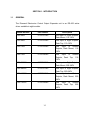
1
COE-08 COE-16 CONTROL OUTPUT EXPANDER USER’S MANUAL Manual Number 517872-1960 Ultrak®, Inc. 4465 Coonpath Road NW Carroll, OH 43112 (740) 756-9222•(800) 443-6680•FAX (740) 756-4237 Issue 1, Revision A – October 1998 – corrected pin-outs for COMM connector on CAT video switcher (page 2-5). Issue 1, Revision B – May 1999 – updated installation drawings to Rev. A 1999 BY ULTRAK, INC. ALL RIGHTS RESERVED PRINTED IN THE UNITED STATES OF AMERICA ULTRAK, INCORPORATED P.O. BOX 200 LANCASTER, OHIO 43130 (740) 756-9222 (800) 443-6681 TECHNICAL SUPPORT ALL RIGHTS RESERVED. NO PART OF THIS PUBLICATION MAY BE REPRODUCED BY ANY MEANS WITHOUT WRITTEN PERMISSION FROM ULTRAK, INCORPORATED. THE INFORMATION IN THIS PUBLICATION IS BELIEVED TO BE ACCURATE IN ALL RESPECTS. HOWEVER, ULTRAK, INCORPORATED CANNOT ASSUME RESPONSIBILITY FOR ANY CONSEQUENCES RESULTING FROM THE USE THEREOF. THE INFORMATION CONTAINED HEREIN IS SUBJECT TO CHANGE WITHOUT NOTICE. REVISIONS OR NEW EDITIONS TO THIS PUBLICATION MAY BE ISSUED TO INCORPORATE SUCH CHANGES. DECLARATION OF CONFORMITY To The European Community Council Directive 89/336/EEC ® ISSUED BY: Ultrak , Inc. 4465 Coonpath Road NW Carroll, OH 43112 USA Tel: (740) 756-9222 Fax: (740) 756-4237 MANUFACTURER: Ultrak , Inc. DATE OF ISSUE: December 22, 1995 TYPE OF EQUIPMENT: CCTV and Security Surveillance Equipment MODEL NUMBER: Alarm Interface Unit AIU-100 - may be followed by any number of alphanumeric characters. Auxiliary Interface Units AIF-100/CO Central Control Unit CCU-100 - may be followed by any number of alphanumeric characters. CCU-150 – may be followed by any number of alphanumeric characters. CCU-200 – may be followed by any number of alphanumeric characters. Joystick Multiplexer MUX-100 – may be followed by any number of alphanumeric characters MUX-05 – may be followed by any number of alphanumeric characters Joystick Controller* JPD-100, JPD-101, JPD-200 - may be followed by any number of alphanumeric characters. Small System Interface* SSI-100 - may be followed by any number of alphanumeric characters. Control Output Expander COE-08, COE-16 - may be followed by any number of alphanumeric characters Control Receiver CRX-610/BX, CRX-801AX, CRX-801BX ® *Standard EN60065 does not apply. STANDARDS TO WHICH CONFORMITY IS DECLARED: EN50081-1 Emissions Standard, and EN50082-1 Immunity Standard. EN55022 Radiated, Class A, EN55022 Conducted, Class A, IEC-1000-4-2, ESD, IEC1000-4-3, RF Fields, IEC-1000-4-4, Fast Transients/Burst. EN60065 Safety Requirements for Mains Operated Electronic and Related Apparatus for Household and Similar General Use ® Ultrak , Inc. hereby declares that the models specified above conform to the directive and standard as specified. Donald L. Stephenson Compliance Engineer 517775-3 Rev. O August 25, 1999 WARNING THIS IS A CLASS A PRODUCT. IN A DOMESTIC ENVIRONMENT, THIS PRODUCT MAY CAUSE RADIO INTERFERENCE IN WHICH CASE THE USER MAY BE REQUIRED TO TAKE ADEQUATE MEASURES. WARNING NOT FOR OUTDOOR USE UNLESS ENCLOSED IN WATERPROOF HOUSING. WARNING TO REDUCE A RISK OF FIRE OR ELECTRIC SHOCK, DO NOT EXPOSE THIS PRODUCT TO RAIN OR MOISTURE UNLESS ENCLOSED IN WATERPROOF HOUSING. NOTE This equipment has been tested and found to comply with the limits for a Class A digital device, pursuant to Part 15 of the FCC Rules. These limits are designed to provide reasonable protection against harmful interference when the equipment is operated in a commercial environment. This equipment generates, uses, and can radiate radio frequency energy and, if not installed and used in accordance with the instruction manual, may cause harmful interference to radio communications. Operation of this equipment in a residential area is likely to cause harmful interference in which case the user will be required to correct the interference at his own expense. IMPORTANT SAFEGUARDS 1. Read Instructions - All the safety and operating instructions should be read before the unit is operated. 2. Retain Instructions - The safety and operating instructions should be retained for future reference. 3. Heed Warnings - All warnings on the unit and in the operating instructions should be adhered to. 4. Follow Instructions - All operating and use instructions should be followed. 5. Cleaning - Unplug the unit from the outlet before cleaning. Do not use liquid cleaners or aerosol cleaners. Use a damp cloth for cleaning. See cleaning procedures under Maintenance. 6. Attachments - Do not use attachments not recommended by the product manufacturer as they may cause hazards. 7. Water and Moisture - Do not use this unit near water - for example, near a bath tub, wash bowl, kitchen sink, or laundry tub, in a wet basement, near a swimming pool, in an unprotected outdoor installation, or any area which is classified as a wet location. 8. Accessories - Do not place this unit on an unstable stand, tripod, bracket, or mount. The unit may fall, causing serious injury to a person and serious damage to the unit. Use only with a stand, tripod, bracket, or mount recommended by the manufacturer, or sold with the product. Any mounting of the unit should follow the manufacturer’s instructions, and should use a mounting accessory recommended by the manufacturer. A cart should be moved with care. Quick stops, excessive force, and uneven surfaces may cause the cart to overturn. 9. Ventilation - Openings in the enclosure, if any, are provided for ventilation and to ensure reliable operation of the unit and to protect it from overheating. These openings must not be blocked or covered. This unit should not be placed in a built-in installation unless proper ventilation is provided or the manufacturer’s instructions have been adhered to. 10. Power Sources - This unit should be operated only from the type of power source indicated on the marking label. If you are not sure of the type of power supply you plan to use consult your dealer or local power company. For units intended to operate from battery power, or other sources, refer to the operating instructions. 11. Grounding or Polarization - This unit may be equipped with a polarized alternating-current line plug (a plug having one blade wider than the other). This plug will fit into the power outlet only one way. This is a safety feature. If you are unable to insert the plug fully into the outlet, try reversing the plug. If the plug should still fail to fit, contact your electrician to replace your obsolete outlet. Do not defeat the safety purpose of the polarized plug. Alternately, this unit may be equipped with a 3-wire grounding-type plug, a plug having a third (grounding) pin. This plug will only fit into a grounding-type power outlet. This is a safety feature. If you are unable to insert the plug into the outlet, contact your electrician to replace your obsolete outlet. Do not defeat the safety purpose of the grounding-type plug. 12. Power-Cord Protection - Power supply cords should be routed so that they are not likely to be walked on or pinched by items placed upon or against them, paying particular attention to cords and plugs, convenience receptacles, and the point where they exit from the equipment. 13. Power Lines - An outdoor system should not be located in the vicinity of overhead power lines or other electric light or power circuits, or where it can fall into such power lines or circuits. When installing an outdoor system, extreme care should be taken to keep from touching such power lines or circuits as contact with them might be fatal. U.S.A. models only - refer to the National Electrical Code Article 820 regarding installation of CATV systems. 14. Overloading - Do not overload outlets and extension cords as this can result in a risk of fire or electric shock. 15. Object and Liquid Entry - Never push objects of any kind into this unit through openings as they may touch dangerous voltage points or short-out parts that could result in a fire or electric shock. Never spill liquid of any kind on the unit. 16. Servicing - Do not attempt to service this unit yourself as opening or removing covers may expose you to dangerous voltage or other hazards. Refer all servicing to qualified service personnel. 17. Damage Requiring Service - Unplug the unit from the outlet and refer servicing to qualified service personnel under the following conditions: a. b. c. d. e. f. When the power-supply cord or plug is damaged. If liquid has been spilled, or objects have fallen into the unit. If the unit has been exposed to rain or water. If the unit does not operate normally by following the operating instructions. Adjust only those controls that are covered by the operating instructions as an improper adjustment of other controls may result in damage and will often require extensive work by a qualified technician to restore the unit to its normal operation. If the unit has been dropped or the cabinet has been damaged. When the unit exhibits a distinct change in performance - this indicates a need for service. 18. Replacement Parts - When replacement parts are required, be sure the service technician has used replacement parts specified by the manufacturer or have the same characteristics as the original part. Unauthorized substitutions may result in fire, electric shock or other hazards. 19. Safety Check - Upon completion of any service or repairs to this unit, ask the service technician to perform safety checks to determine that the unit is in proper operating condition. 20. Coax Grounding - If an outside cable system is connected to the unit, be sure the cable system is grounded. U.S.A. models only - Section 810 of the National Electrical Code, ANSI/NFPA No. 701981, provides information with respect to proper grounding of the mount and supporting structure, grounding of the coax to a discharge unit, size of grounding conductors, location of discharge unit, connection to grounding electrodes, and requirements for the grounding electrode. 21. Lightning - For added protection of this unit during a lightning storm, or when it is left unattended and unused for long periods of time, unplug it from the wall outlet and disconnect the cable system. This will prevent damage to the unit due to lightning and power-line surges. SAFETY PRECAUTIONS CAUTION RISK OF ELECTRIC SHOCK, DO NOT OPEN CAUTION: TO REDUCE THE RISK OF ELECTRICAL SHOCK, DO NOT OPEN COVERS. NO USER SERVICEABLE PARTS INSIDE. REFER SERVICING TO QUALIFIED SERVICE PERSONNEL. This label may appear on the bottom of the unit due to space limitations. The lightning flash with an arrowhead symbol, within an equilateral triangle, is intended to alert the user to the presence of uninsulated “dangerous voltage” within the product’s enclosure that may be of sufficient magnitude to constitute a risk of electric shock to persons. The exclamation point within an equilateral triangle is intended to alert the user to presence of important operating and maintenance (servicing) instructions in the literature accompanying the equipment. 220-240 Vac, 50 Hz power cords, input and output, must comply with the latest versions of IEC Publication 227 or IEC Publication 245. WARNING TO PREVENT FIRE OR SHOCK HAZARD, DO NOT EXPOSE THIS UNIT TO RAIN OR MOISTURE. HANDLING ELECTROSTATIC-SENSITIVE DEVICES ATTENTION OBSERVE PRECAUTIONS FOR HANDLING ELECTROSTATIC SENSITIVE DEVICES WARNING ELECTROSTATIC SENSITIVE DEVICE. USE PROPER CMOS/MOSFET HANDLING PRECAUTIONS TO AVOID ELECTROSTATIC DISCHARGE. NOTE: Grounded wrist straps must be worn and proper ESD safety precautions observed when handling the electrostatic-sensitive printed circuit boards. TABLE OF CONTENTS Page SECTION 1. INTRODUCTION ....................................................................................1-1 1.1 GENERAL ......................................................................................................1-1 1.2 SPECIFICATIONS .........................................................................................1-2 SECTION 2. INSTALLATION AND INTERCONNECTIONS.......................................2-1 2.1 EQUIPMENT INTERCONNECTIONS............................................................2-1 2.1.1 JAD-832 Controller..................................................................................2-2 2.1.2 MUX-05 Multiplexer.................................................................................... 2 2.1.3 JPD-101 Controller..................................................................................2-3 2.1.4 CCU-100 or CCU-100/A Central Control Unit .........................................2-3 2.1.5 CATS Family Video Switcher.................................................................2-4 2.1.6 COE-08/A or COE-16/A Control Output Expander Unit ..........................2-6 2.1.7 FastScan/SmartScan Units .....................................................................2-6 2.2 INSTALLATION DRAWINGs .........................................................................2-6 SECTION 3. OPERATION ..........................................................................................3-1 3.1 controls and indicators ...................................................................................3-1 3.2 operatiON.......................................................................................................3-2 SECTION 4. MAINTENANCE .....................................................................................4-1 4.1 PREVENTIVE MAINTENANCE .....................................................................4-1 4.2 Troubleshooting .............................................................................................4-1 LIST OF FIGURES Page Figure 3-1. CONTROLS AND INDICATORS...............................................................3-1 i LIST OF DRAWINGS Page Installation, COE-08/R Control Output Expander Unit, Rack Mount (D/N 517872-1440).......................................................................................................2-7 Installation, COE-16/R Control Output Expander Unit, Rack Mount (D/N 517872-2440).......................................................................................................2-8 Installation, COE-08/D Control Output Expander Unit, Desk Top (D/N 517872-3440).......................................................................................................2-9 Installation, COE-16/R Control Output Expander Unit, Desk Top (D/N 517872-4440).....................................................................................................2-10 ii SECTION 1. INTRODUCTION 1.1 GENERAL The Diamond Electronics Control Output Expander unit is an RS-422 active driver available in eight models. Model Number Part Number Description COE-08/R 517872-1040 0ne Input to Eight Outputs, Rack Mount, 110-120V COE-08/D 517872-3040 One Input to Eight Outputs, Desk Top, 110-120V COE-16/R 517872-2040 One Input to Sixteen Outputs, Rack Mount, 110120V COE-16/D 517872-4040 One Input to Sixteen Outputs, Desk Top, 110120V COE-08/R/X 517872-5040 One Input to Eight Outputs, Rack Mount, 220-240V COE-08/D/X 517872-7040 One Input to Eight Outputs, Desk Top, 220-240V COE-16/R/X 517872-6040 One Input to Sixteen Outputs, Rack Mount, 220240V COE-16/D/X 517872-8040 One Input to Sixteen Outputs, Desk Top, 220240V 1-1 These units provide the user the capability of expanding the number of receivers in the system. The input can be either a JAD-832 Controller, MUX-05 Multiplexer, JPD-101 Controller, CCU-100 Central Control Unit, CATS Video Switcher, or another Control Output Expander Unit. Each output is capable of transmitting control data to ten FastScan/SmartScan units as long as the combined cable distance from each output on the control output expander unit to the last dome in the chain is no more than 4000 feet. 1.2 SPECIFICATIONS ELECTRICAL Power Requirements: Fuse: Input: Outputs: 110-120V , 50/60 Hz 0.080A 220-240V, 50/60 Hz, 0.040A 120 Vac Power Input T.080 220 Vac Power Input T.040 One 4-Position Plug In Terminal Block COE-08 Two 12-Position Plug In Terminal Blocks (+, - and SH for 8 control outputs) COE-16 Four 12-Position Plug In Terminal Blocks (+, - and SH for 16 control outputs) 1-2 MECHANICAL Installation: Dimensions: Weight: Finish: 19" Rack Mountable in accordance with EIA Standard RS-310 or Desk Top. Rack Mounting holes accommodate #10 mounting screws 1.72" H x 19" W x 10.51" (D) (44.4 mm H x 490.1 mm W x 266.9 mm D) 5 lb. (2.3 kg.) Front Panel: Light gray Chassis & Rear Panel: Alodine 1200 ENVIRONMENTAL Operating Temperature: Humidity Limits: 32°F to 122°F (0°C to 50°C) 0% to 95% non-condensing 1-3 SECTION 2. INSTALLATION AND INTERCONNECTIONS 2.1 EQUIPMENT INTERCONNECTIONS Use single twisted-pair shielded RS422 cable, Diamond Electronics part number 849518-0334, (Carol CO841 or equivalent) for connection to the input and output plug-in terminal blocks. The cable shield should be carried through each unit, but only connected at one end. The input for the active RS422 expander unit can be either a JAD-832 Controller with a DIA-01, a MUX-05 Multiplexer, a JPD-101 Controller with a DIA-01, a CCU-100 Central Control Unit, a CATS Video Switcher, or another COE Control Output Expander. Up to ten receivers can be daisy-chain wired from each output. The maximum distance to the last receiver in a chain is 4000 feet. A 6-foot power cord with a NEMA 5-15P plug is supplied with the 110-120V unit. This is a 3-wire grounding-type plug. This is a safety feature. If you are unable to insert the plug into the outlet, contact your electrician to replace your electrical outlet. A 6-foot power cord with bare leads is supplied with the 220-240V unit. The installer must supply and install the site required plug. This power cord must be connected to a true earth ground. Brown = Hot Blue = Neutral Green = Ground 2-1 2.1.1 JAD-832 Controller If a JAD-832 Controller is connected directly to a COE unit, the JAD-832 must be plugged into a DIA-01 Control Interface Adapter and then the DIA01 connected to the input on the COE. The DIA-01 provides the +5V power required to operate the JAD-832. 2.1.2 DIA-01 to COE Input TX+ Black to + TX- Red to - MUX-05 Multiplexer Up to five JAD-832 Controllers can be connected to a MUX-05 Multiplexer. Four of the JAD-832 controllers must be plugged into a DIA-01 and then the DIA-01's are connected to the inputs on rear panel of the MUX-05. One of the JAD-832 Controllers can be plugged directly into the front panel of the MUX-05. Then one of the MUX-05 outputs is connected to the COE unit input. MUX-05 to COE Input Pin 2, TX+ to + Pin 1, TX- to - Pin 3, GND to S Channel 2 through 8 Output 2-2 A 48” cable assembly, part number 517565-2020, is available for connection from the MUX-05 to a COE unit. This cable has the DIN connector from the MUX-05 installed on one end. Cable Assembly 517565-2020 2.1.3 MUX-05 DIN CONNECTOR Pin 1, TX- WIRE COLOR BLK COE INPUT - Pin 2, TX+ RED + JPD-101 Controller If a JPD-101 Controller is connected to a COE unit, the JPD-101 must be plugged into a DIA-01 Control Interface Adapter. Then the DIA-01 is connected to the COE unit. 2.1.4 DIA-01 to COE Input TX+ Black to + TX- Red to - CCU-100 or CCU-100/A Central Control Unit The CCU-100 Central Control Unit has two control outputs on channels 4 and 7. Each control output channel could be connected to a COE unit to increase the number of domes from 20 to up to 250. CCU-100 (CHS 4 & 7) to COE Input Pin 1, TX- to - Pin 2, TX+ to + Pin 3, GND to S 2-3 The CCU-100/A Central Control Unit has three control outputs on channels 3, 4, and 7. Each control output could be connected to a COE unit increasing the number of domes from 30 to up to 250. CCU-100/A (CHS 3, 4, 7) to COE Input Pin 1, TX- to - Pin 2, TX+ to + Pin 3, GND to S A 48” cable assembly, part number 517565-2020, is available for connection from the CCU-100 or CCU-100A to a COE unit. This cable has the DIN connector from the MUX-05 installed on one end. Cable Assembly 517565-2020 CCU-100 or CCU-100/A DIN CONNECTOR WIRE COLOR COE INPUT Pin 1, TXBLK Pin 2, TX+ 2.1.5 RED + CATS Family Video Switcher The CATS Video Switchers have a communication connector (COMM) that supplies four communication ports to the domes. Each communication port can control up to ten daisy-chained domes as long as the maximum cable distance from the communication port to the farthest dome does not exceed 4000 feet. Each communication port could be connected to a COE unit to increase the number of domes in the system. 2-4 NOTE If a MUX-05 Multiplexer or a CCU-100 or CCU100A Central Control Unit is installed, the video switcher communication ports are not used. Use the communication ports on the MUX-05 or the CCU-100 or CCU-100/A. Video Switcher COMM Connector Port 1 to COE Input Pin 1, + to + Pin 2, - to - Pin 4, Gnd to S Pin 7, + to + Pin 3, - to - Pin 5, GND to S Pin 15, + to + Pin 11, - to - Pin 8, Gnd to S Pin 16, + to + Pin 12, - to - Pin 9, Gnd to S Port 2 Port 3 Port 4 2-5 2.1.6 COE-08/A or COE-16/A Control Output Expander Unit Any of the outputs on a COE unit can be connected to the input on another COE unit to further increase the number of domes in a system. A COE unit is the same load on the communication line as one dome. 2.1.7 2.2 COE Output to COE Input + to + - to - S to S FastScan/SmartScan Units COE Output to FastScan or SmartScan to FastScan or SmartScan + to Pin 4, Data+ to Pin 4, Data+ - to Pin 3, Data- to Pin 3, Data- S to Cable Shield to Cable Shield INSTALLATION DRAWINGS The following drawings are provided for assistance during installation of the COE-08/A and COE-16/A Control Output Expander Units. Title Page COE-08/R Active Control Output Expander Unit (D/N 517872-1440) ..............................................................................2-7 COE-16/R Control Output Expander Unit, Rack Mount (D/N 517872-2440) ..............................................................................2-8 COE-08/D Control Output Expander Unit, Desk Top (D/N 517872-3440) ..............................................................................2-9 COE-16/D Control Output Expander Unit, Desk Top (D/N 517872-4440) ..............................................................................2-10 2-6 CONTROL OUTPUT EXPANDER 2-7 CONTROL OUTPUT EXPANDER 2-8 CONTROL OUTPUT EXPANDER 2-9 CONTROL OUTPUT EXPANDER 2-10 SECTION 3. OPERATION 3.1 CONTROLS AND INDICATORS Figure 3-1. CONTROLS AND INDICATORS FRONT VIEW POWER INDICATOR The power indicator lights red when the unit is plugged into an AC outlet. REAR VIEW 110VAC, 220VAC VOLTAGE SELECTOR This selector sets the power input to 110-120V or 220-240V. Use a small blade screwdriver to switch between 110Vac and 220Vac. The fuse must match the power input selected. A T.080A fuse is required for the 110-120V power input. A T.040A fuse is required for 220-240V power input. 3-1 3.2 OPERATION After power is applied to the Control Output Expander Unit, operation of the unit is automatic. There are no operating procedures for this unit. The control data is sent from the controller to any interface equipment such as the DIA-01 Control Interface Adapter, CCU-100 Central Control Unit, or Video Switcher, and then to the Control Output Expander Unit. The Control Output Expander Unit sends all control data out the output ports. 3-2 SECTION 4. MAINTENANCE 4.1 PREVENTIVE MAINTENANCE Use of preventive maintenance allows detection and correction of minor faults before they become serious enough to cause equipment failure. As a result, major repairs can be avoided, and the equipment can be maintained in an operable condition with a minimum of maintenance. Every 3 months, perform the following. 4.2 1. Inspect all interface connecting cabling for deterioration or other damage. 2. Clean the front panel with a soft cloth using any mild commercial cleaner. TROUBLESHOOTING If problems occur at the initial installation phase, verify that the procedures in Section 2 have been performed correctly. Because this unit is just one part of an overall system, it may be necessary to verify that the other equipment types have been installed and are operating correctly before assuming the problem exists at the Control Expander Unit. 4-1 If problems still exist after verifying correct installation and the problem has been isolated to the COE, then it must be removed for servicing. THERE ARE NO USER-SERVICEABLE PARTS COMPRISING THE CONTROL OUTPUT EXPANDER UNIT. REFER SERVICING TO QUALIFIED PERSONNEL ONLY. Any equipment returned to Ultrak for warranty or service repair must have a prior written Authorization to Return Material (ARM) form completed for its repair. Contact: Ultrak®, Inc. Service Department 4465 Coonpath Road Carroll, Ohio 43112 (740) 756-9222 Toll Free U.S.A. 1-800-443-6681 4-2