1
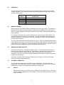
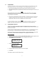
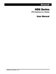
KD6 Z-SERIES DOME
Buy Ultrak
Cameras & Parts
@ TLS Electronics
OPERATION AND PROGRAMMING
Manual Number 518854-1960
Ultrak®
4465 Coonpath Road
Carroll, OH 43112
(800) 443-6680•(740) 756-9222•FAX (740) 756-4237
Issue 1, Revision D – April 25 , 2001
Issue 1 – December 21, 2000
Issue 1, Revision A – January 5, 2001 – changed model number; added note for setting address
regarding alpha character A in serial number.
Issue 1, Revision B – January 25, 2001 – added worksheets for Camera Serial #, PreShots and
VectorScans.
Issue 1, Revision C – March 1, 2001 – added CE declaration, Class A Product Warning, and FCC Note.
Issue 1, Revision D – April 25, 2001 – added find home function.
©2000-2001 By Ultrak®, Inc.
All Rights Reserved
Printed In The United States Of America
Ultrak, Incorporated
4465 Coonpath Road, NW
Carroll, Ohio 43112
(740) 756-9222
Sales 1-800-443-6680 (Toll Free USA)
Technical Support 1-800-443-6681 (Toll Free USA)
ALL RIGHTS RESERVED. NO PART OF THIS PUBLICATION MAY BE REPRODUCED BY ANY MEANS WITHOUT WRITTEN
PERMISSION FROM ULTRAK®, INCORPORATED.
THE INFORMATION IN THIS PUBLICATION IS BELIEVED TO BE ACCURATE IN ALL RESPECTS. HOWEVER, ULTRAK,
INCORPORATED CANNOT ASSUME RESPONSIBILITY FOR ANY CONSEQUENCES RESULTING FROM THE USE THEREOF.
THE INFORMATION CONTAINED HEREIN IS SUBJECT TO CHANGE WITHOUT NOTICE. REVISIONS OR NEW EDITIONS TO
THIS PUBLICATION MAY BE ISSUED TO INCORPORATE SUCH CHANGES.
WARNING
THIS IS A CLASS A PRODUCT. IN A DOMESTIC ENVIRONMENT,
THIS PRODUCT MAY CAUSE RADIO INTERFERENCE IN WHICH
CASE THE USER MAY BE REQUIRED TO TAKE ADEQUATE
MEASURES.
WARNING
TO REDUCE A RISK OF FIRE OR ELECTRIC SHOCK, DO NOT
EXPOSE THIS PRODUCT TO RAIN OR MOISTURE UNLESS
ENCLOSED IN A WATERPROOF HOUSING.
NOTE
This equipment has been tested and found to comply with the limits for a
Class A digital device, pursuant to Part 15 of the FCC Rules. These
limits are designed to provide reasonable protection against harmful
interference when the equipment is operated in a commercial
environment. This equipment generates, uses, and can radiate radio
frequency energy and, if not installed and used in accordance with the
instruction manual, may cause harmful interference to radio
communications. Operation of this equipment in a residential area is
likely to cause harmful interference in which case the user will be
required to correct the interference at his own expense.
DECLARATION OF CONFORMITY
ISSUED BY:
To The European Community Council Directive 89/336/EEC
Ultrak, Inc.
4465 Coonpath Road NW
Carroll, OH 43112
USA
Tel: (740) 756-9222
Fax: (740) 756-4237
MANUFACTURER:
Ultrak, Inc.
DATE OF ISSUE:
July 31, 1998
TYPE OF EQUIPMENT:
CCTV and Security Surveillance Equipment
MODEL NUMBER:
Domes*
DD:
May be followed by any number of alphanumeric characters. Can
not contain an “X” after the seventh field. (Note: “-“ are not
considered fields.)
Scans*
DF, DS, DC, or DH:
May be followed by any number of alphanumeric characters. Can
not contain an “H” after the seventh field.
D1F, D1S, D1C, or D1H:
May be followed by any number of alphanumeric characters. Can
not contain an “X” after the seventh field.
SmartScan III’s*
39, 3A, 3B, or 3C:
May be followed by any number of alphanumeric characters. Must
contain a “C” in the seventh field or after.
UltraDome KD6*
KD6
May be followed by any number of alphanumeric characters. Must
contain a “P” in the seventh field.
KDS
May be followed by any number of alphanumeric characters.
KD6 Z-Series*
KDZ
May be followed by any number of alphanumeric characters.
Yokes*
FX-X1, SM-X1, FX9-X1, FX9-X2, SM9-X1, SM9-X2
Power Supply
TR-24/D/CE, TR-24/WSPX
*Standard EN60065 does not apply.
2*Standard 87/404/EEC Simple Pressure Directive does not apply. Pressure is less than 0.5273 kg/cm .
STANDARDS TO WHICH
CONFORMITY IS DECLARED:
EN50081-1 Emissions Standard, and EN50082-1 Immunity Standard.
EN55022 Radiated, Class A, EN55022 Conducted, Class A, IEC-1000-4-2,
ESD,
IEC-1000-4-3, RF Fields, IEC-1000-4-4, Fast Transients/Burst.
EN60065 - Safety Requirements for Mains Operated Electronic and Related
Apparatus for Household and Similar General Use.
Ultrak, Inc. hereby declares that the models specified above conform to the directive and standard
as specified.
Donald L. Stephenson
Compliance Engineer
517775-5
Rev. L
March 1, 2001
IMPORTANT SAFEGUARDS
1.
Read Instructions - All the safety and operating instructions should be read before the unit is
operated.
2.
Retain Instructions - The safety and operating instructions should be retained for future reference.
3.
Heed Warnings - All warnings on the unit and in the operating instructions should be adhered to.
4.
Follow Instructions - All operating and use instructions should be followed.
5.
Cleaning - Unplug the unit from the outlet before cleaning. Use only non-abrasive cleaners for
acrylic plastic on dome.
6.
Water and Moisture - Do not use this unit near water or in an unprotected outdoor installation, or
any area which is classified as a wet location.
7.
Accessories - Do not place this unit on an unstable stand, tripod, bracket, or mount. The unit may
fall, causing serious injury to a person and serious damage to the unit. Use only with a stand,
tripod, bracket, or mount recommended by the manufacturer, or sold with the product. Any
mounting of the unit should follow the manufacturer’s instructions, and should use a mounting
accessory recommended by the manufacturer.
8.
Power Sources - This unit should be operated only from the type of power source indicated on
the marking label.
9.
Grounding or Polarization – The power supply provided with this unit may be equipped with a
polarized alternating-current line plug (a plug having one blade wider than the other). This plug
will fit into the power outlet only one way. This is a safety feature. If you are unable to insert the
plug fully into the outlet, try reversing the plug. If the plug should still fail to fit, contact your
electrician to replace your obsolete outlet. Do not defeat the safety purpose of the polarized plug.
Alternately, this unit may be equipped with a 3-wire grounding-type plug, a plug having a third
(grounding) pin. This plug will only fit into a grounding-type power outlet. This is a safety feature.
If you are unable to insert the plug into the outlet, contact your electrician to replace your obsolete
outlet. Do not defeat the safety purpose of the grounding-type plug.
10.
Power-Cord Protection - Power supply cords should be routed so that they are not likely to be
walked on or pinched by items placed upon or against them, paying particular attention to cords
and plugs, convenience receptacles, and the point where they exit from the appliance.
11.
Overloading - Do not overload outlets and extension cords as this can result in a risk of fire or
electric shock.
12.
Object and Liquid Entry - Never push objects of any kind into this unit through openings as they
may touch dangerous voltage points or short-out parts that could result in a fire or electric shock.
Never spill liquid of any kind on the unit.
13.
Servicing - Do not attempt to service this unit yourself as opening or removing covers may
expose you to dangerous voltage or other hazards. Refer all servicing to qualified service
personnel.
14.
Damage Requiring Service - Unplug the unit from the outlet and refer servicing to qualified
service personnel under the following conditions:
a.
b.
c.
d.
e.
When the power-supply cord or plug is damaged.
If liquid has been spilled, or objects have fallen into the unit.
If the unit has been exposed to rain or water.
If the unit does not operate normally by following the operating instructions. Adjust only
those controls that are covered by the operating instructions as an improper adjustment
of other controls may result in damage and will often require extensive work by a qualified
technician to restore the unit to its normal operation.
If the unit has been dropped or the enclosure has been damaged.
f.
When the unit exhibits a distinct change in performance - this indicates a need for
service.
15.
Replacement Parts - When replacement parts are required, be sure the service technician has
used replacement parts specified by the manufacturer or have the same characteristics as the
original part. Unauthorized substitutions may result in fire, electric shock or other hazards.
16.
Safety Check - Upon completion of any service or repairs to this unit, ask the service technician
to perform safety checks to determine that the unit is in proper operating condition.
17.
Lightning - For added protection of this unit during a lightning storm, or when it is left unattended
and unused for long periods of time, unplug it from the wall outlet and disconnect the cable
system. This will prevent damage to the unit due to lightning and power-line surges.
SAFETY PRECAUTIONS
CAUTION
RISK OF ELECTRIC
SHOCK, DO NOT OPEN
CAUTION: TO REDUCE THE RISK OF ELECTRICAL SHOCK, DO NOT OPEN COVERS. NO USER
SERVICEABLE PARTS INSIDE. REFER SERVICING TO QUALIFIED SERVICE PERSONNEL.
This label may appear on the bottom of the unit due to space limitations.
The lightning flash with an arrowhead symbol, within an equilateral triangle, is
intended to alert the user to the presence of uninsulated “dangerous voltage” within
the product’s enclosure that may be of sufficient magnitude to constitute a risk of
electric shock to persons.
The exclamation point within an equilateral triangle is intended to alert
the user to presence of important operating and maintenance
(servicing) instructions in the literature accompanying the equipment.
220-240 Vac, 50 Hz power cords, input and output, must comply with the latest
versions of IEC Publication 227 or IEC Publication 245.
WARNING
TO PREVENT FIRE OR SHOCK HAZARD, DO NOT EXPOSE THIS
UNIT TO RAIN OR MOISTURE.
HANDLING ELECTROSTATIC-SENSITIVE DEVICES
ATTENTION
OBSERVE PRECAUTIONS
FOR HANDLING
ELECTROSTATIC
SENSITIVE
DEVICES
WARNING
ELECTROSTATIC SENSITIVE DEVICE. USE PROPER
CMOS/MOSFET HANDLING PRECAUTIONS TO AVOID
ELECTROSTATIC DISCHARGE.
NOTE: Grounded wrist straps must be worn and proper ESD safety
precautions observed when handling the electrostatic-sensitive printed
circuit boards.
TABLE OF CONTENTS
Page
1.0
DESCRIPTION.............................................................................................................................1
1.1
FEATURES ..................................................................................................................................1
2.0
ADDRESSING .............................................................................................................................1
3.0
OPERATION ................................................................................................................................2
3.1
MANUAL CONTROL....................................................................................................................2
3.2
MECHANICAL HOME POSITION ...............................................................................................2
3.3
AUTOMATIC OPERATION..........................................................................................................2
3.3.1
PreShot................................................................................................................................2
3.3.2
VectorScan (Video Tour).....................................................................................................3
4.0
PROGRAMMING .........................................................................................................................4
4.1
PROGRAMMING PRESHOTS ....................................................................................................4
4.1.1
Editing PreShots..................................................................................................................5
4.2
PROGRAMMING VECTORSCANS.............................................................................................5
4.2.1
Editing VectorScans ............................................................................................................6
LIST OF TABLES
Table 1. CONTROLLER COMMANDS .........................................................................................................6
i
This page left blank intentionally.
ii
KD6 Z-SERIES DOME
OPERATION AND PROGRAMMING
1.0
DESCRIPTION
A KD6 Z-Series Dome consists of:
- A pan and tilt assembly, often referred to as a "scan".
- A color camera (NTSC or PAL) with an auto-focus and auto-iris lens.
- Top Dome
- Bottom Dome
The KD6 Z-Series Dome can be mounted in a dropped ceiling, hard ceiling, indoor pendant
dome, or outdoor weather dome. The bottom domes are designed to blend with building
aesthetics and are available in smoked or clear.
1.1
FEATURES
The scan provides continuous 360° pan rotation at rate-proportional controlled speeds. The KD6
Z-Series Dome features manual pan speeds of 1° to 180°/second and manual tilt speeds of 2°
to 90°/second.
Using a Diamond JPD Series controller, an operator can control the pan and tilt functions and the
lens zoom, focus, and iris functions of the camera lens. The camera lens has auto iris and auto
focus features. The camera lens is a 4m-64mm (16x) zoom lens with a 2X digital magnifier.
The receiver board on the KD6 Z-Series Dome can be programmed to store 64 PreShots and 3
VectorScans. All programming is backed up using a serial EEPROM. This back up prevents
programming from being lost if power is removed from the scan assembly for any reason.
2.0
ADDRESSING
Each KD6 Z-Series Dome must be given a unique system address. This address is the camera
number an operator uses to call-up and control the dome.
A JPD Series Controller (JPD-101, JPD-100, JPD-200P, JPD-100P) is used to set the address of
a KD6 Z-Series Dome. You must know the 8-digit serial number of the unit. The serial number
is located on the side of the mounting bracket of the pan and tilt assembly.
Press OPT on the JPD controller to view the LCD menu options
Press 1 (MISC)
1
Press 2 (SET ADD) to set the address
2
Enter the Serial Number (8 digits) of the KD6 Z-Series Dome (SN-)
*
Enter the leading character A of the serial number as a 0 .
Press Enter.
SN#
Enter
Enter the desired system address (camera number) of the dome (1-250)
Press Enter.
The LCD on the controller displays the message, “Updating Address”.
*
OPT
Input Serial Number (S/N:) A1012585 as 01012585.
1
###
Enter
3.0
OPERATION
The KD6 Z-Series Dome can be controlled and programmed using any Diamond JPD Series
Joystick Controllers. The controllers must have the following firmware revision level to support
the KD6 Z-Series Dome.
Controller
Model
JPD101
JPD100
JPD100P
JPD100PLO
JPD200P
3.1
Firmware Part Number
and Revision L
518007-3980, Revision F or later
518007-1980, Revision E or later
518007-2980, Revision D or later
518007-4980
518292-1980, Revision A or later
MANUAL CONTROL
Manual control of a KD6 Z-Series Dome includes pan, tilt, zoom, focus, and iris. The address of
the KD6 Z-Series Dome the operator wants to control must be selected as the control camera.
When an operator performs a command, the controller sends out the control data with the control
camera address.
For example, the operator has camera 2 selected as the control camera on the controller. The
operator performs the tilt function on the controller. The controller sends out the tilt command
and camera address 2. All the domes receive the command, but only the dome with address 2
performs the tilt command.
The camera lens in the dome provides automatic iris control. The lens iris adjusts automatically
to the brightness of the scene (unless manual iris is selected at the controller). If the video scene
is dark and auto iris is enabled, the camera automatically opens the lens iris. If the video scene is
bright and auto iris is enabled, the camera automatically closes the lens iris.
3.2
MECHANICAL HOME POSITION
Each unit has a factory set, mechanical "HOME" position. The mechanical home position is a
reference point for the pan and tilt positions. Upon power up, the dome finds its home position.
Every time a VectorScan is started, the scan finds it home position first, then starts the
VectorScan. The unit must be able to find its mechanical home position to program and perform
PreShots and VectorScans.
An operator can send a Scan to its home position at any time using a JPD Series Controller
(OPT>2>2) or KBD-100A Keyboard (F9).
3.3
AUTOMATIC OPERATION
The scan can be programmed to store PreShots and VectorScans. Scan assemblies are
programmed using a JPD Series Controller. Refer to paragraphs 4.1 and 4.2 of this manual for
programming procedures for PreShots and VectorScans, respectively.
3.3.1
PreShot
When a dome receives a command to go to a PreShot, the scan goes to the pan, tilt, zoom,
and focus positions programmed in the PreShot. Perform the following procedure to send a
scan to a PreShot.
2
JPD Series Controller (secondary control camera, if selected; if not, primary control camera)
Note: refer to the JPD Series Controller user’s manual for operation of primary control
and secondary control cameras.
1.
2.
Enter the PreShot number (1-64).
Press PSHOT.
Example: Send primary control camera (no secondary camera selected) to PreShot 5.
Press 5 on the numeric keypad.
Press PSHOT on the function keypad.
3.3.2
VectorScan (Sequence of PreShots)
When a scan receives a command to run a VectorScan, the scan finds its mechanical home
position, then goes to the first PreShot programmed in the VectorScan at maximum velocity
(180°/second), and remains at that PreShot for the programmed dwell time. Then the scan
goes to the next PreShot in the VectorScan at the maximum velocity and remains at that
PreShot for the specified dwell time, etc. The amount of time the scan takes to go to each
PreShot depends on the distance to the next PreShot’s pan and tilt coordinates. A
VectorScan repeats continuously until the scan receives a manual control command, a
PreShot command, or a different VectorScan command.
Run VectorScan
VectorScans can be started by an operator from any JPD series controller.
NOTE
Continuously means the scan unit runs the VectorScan from beginning to end; then
repeats the list until halted by an operator.
CAUTION
Continuous VectorScan Operation For Extended Periods Of Time (> 8
Hours) Is Not Recommended. Continuous Operation Results In Increased
Zoom Lens Failure and Maintenance Expense.
JPD Series Controller (secondary control camera, if selected; if not, primary control camera)
Note: refer to the JPD Series Controller user’s manual for operation of primary control
and secondary control cameras.
1.
2.
Press the VectorScan number (1-3).
Press VSCAN.
Stop VectorScan
To stop a VectorScan perform one of the following
a)
Manually control the dome by moving the joystick on the JPD series controller in
any direction
b)
Press OPT, then 2, then 1 on the JPD series controller.
c)
Press Esc on the KBD-100A keyboard (connected to the JPD series controller)
d)
Send the dome to a PreShot
e)
Start another VectorScan
3
4.0
PROGRAMMING
A JPD Series Controller is used to program and store PreShots and VectorScans in the scan.
The following criteria has to be met to program (or edit existing programming in) a scan.
1. The scan being programmed must be the primary control camera on the controller.
2. The controller being used for programming must have manual control (pan, tilt, zoom, etc.) of
the scan.
NOTE
If the controller does not have manual control of the scan, press CNTL on the controller.
If pressing CNTL does not work, verify the address of the scan unit. Refer to paragraph
2.0 for setting the unit’s address.
3. The scan unit must be able to find its home position. To find home, the pan, tilt, and zoom
feedback connections must all be functional. If the unit does not find home, it cannot be
programmed. Return your unit to a qualified service center for repair.
NOTE
If an MSI-100 Medium System Interface unit or CCU-200 Communications Control Unit is
installed in the system, the operator must know the password to access programming.
4.1
PROGRAMMING PRESHOTS
A PreShot is a predefined scan and lens position (including the pan, tilt, zoom, and focus
settings). The PreShot is saved with a number. The operator uses the PreShot number to send
the scan to the PreShot.
A total of 64 (01-64) PreShot positions are programmable per unit. The PreShots are stored on
the receiver board. A Diamond JPD series controller is required to program PreShots.
Perform the following procedure to program a PreShot in the KD6 Z-Series Dome using a JPD101 Controller. Use the worksheet in paragraph 4.3 to log programmed PreShots.
JPD-101 Controller
a. Adjust the pan, tilt, zoom, and focus of the KD6 Z-Series Dome using the joysticks on the
JPD Series Controller until the desired scene is displayed on the monitor.
b. Press PRGM on the function keypad.
1>Program Funct. Key
2>Quick Prg. Preshot
c.
Press 2 on the numeric keypad.
..Program Preshot…
Enter shot No.-__
d. Press the PreShot number(s), 1-64, on the numeric keypad.
e. Press Enter.
The PreShot is stored in the KD6 Z-Series Dome.
4
Perform the following procedure to program a PreShot in the KD6 Z-Series Dome using a
JPD100, JPD100P, or JPD200P Controller.
JPD100, JPD100P, or JPD200P Controller
a. Adjust the pan, tilt, zoom, and focus of the KD6 Z-Series Dome using the joysticks on the
controller until the desired scene is displayed on the monitor.
b. Press the PreShot number(s), 1-64, on the numeric keypad.
c.
Press PRGM on the function keypad.
d. Press Enter.
The PreShot is stored in the KD6 Z-Series Dome.
4.1.1
Editing PreShots
Follow the procedures for programming PreShots.
4.2
PROGRAMMING VECTORSCANS
VectorScans are one or more PreShots, from the same unit, grouped together and saved with a
number. The amount of time (dwell) the scan remains at each PreShot can be programmed and
saved in the VectorScan. A total of three (1-3) VectorScans are programmable per scan. Each
VectorScan File can contain a maximum of 16 PreShots.
Perform the following procedure to program and store a VectorScan (in the control camera
displayed on the programming controller). Use the worksheet in paragraph 4.3 to log
programmed VectorScans.
Press the OPT key.
Press 4 (PROG).
†
Press 2 (VectorScan ).
Enter the VectorScan # (1-3)
Press Enter.
st
Enter the 1 PreShot # (1-64).
Press Enter.
Enter a dwell time (0-30 seconds).
Press Enter.
Enter the next PreShot # (1-64).
Press Enter
Enter a dwell time (0-30 seconds).
†
Tour (Selection 1) on the JPD Series Controller is not available for the KD6 Z-Series product.
5
Press Enter.
Continue entering PreShot numbers and dwell times (up to 16).
•
•
Press Clear when done programming.
4.2.1
Editing VectorScans
Edit VectorScans by reprogramming the VectorScan as described in paragraph 4.2. Note:
All previous programming for the VectorScan is lost.
Table 1. CONTROLLER COMMANDS
Notes:
Keystrokes Are Separated By The Symbol >.
JPD Series Controller
Command
PreShot # > PSHOT
VectorScan # > VSCN.
Definition
PreShot # >PRGM (JPD100, JPD100P, JPD200P)
PRGM>2>PreShot #>Enter (JPD101)
OPT>4>2>VectorScan #>
PreShot#>Dwell>PreShot#>Dwell>
•••
PreShot #>Dwell>Clear
4.3
"GO TO" PreShot
Run VectorScan Continuously
Program PreShot (1-64) – stores present
pan/tilt/zoom/focus settings for control camera
Program VectorScan
3 VectorScans (1-3) can be programmed with
up to 16 PreShots each.
PROGRAMMING WORKSHEETS
The following worksheets are provided to log programmed PreShots and VectorScans. A log
should be maintained for each camera.
6
CAMERA LOG
Serial #
(8-digits)
Camera
System Address
(1-250)
Serial #
(8-digits)
Camera
System Address
(1-250)
________
___
________
___
________
___
________
___
________
___
________
___
________
___
________
___
________
___
________
___
________
___
________
___
________
___
________
___
________
___
________
___
________
___
________
___
________
___
________
___
________
___
________
___
________
___
________
___
________
___
________
___
________
___
________
___
________
___
________
___
________
___
________
___
________
___
________
___
________
___
________
___
________
___
________
___
________
___
________
___
________
___
________
___
________
___
________
___
7
PRESHOT LOG
Camera
Serial # _ _ _ _ _ _ _ _ (8 digits)
System Address _ _ _ (1-250)
PreShot #
View
8
VECTORSCAN LOG
Camera
Camera
Serial # _ _ _ _ _ _ _ _ (8 digits)
Serial # _ _ _ _ _ _ _ _ (8 digits)
System Address _ _ _ (1-250)
System Address _ _ _ (1-250)
VectorScan # __ (1-3)
Dwell Time
PreShot # (1-64)
(0-30)
VectorScan # __ (1-3)
Dwell Time
PreShot # (1-64)
(0-30)
Camera
Serial # _ _ _ _ _ _ _ _ (8 digits)
System Address _ _ _ (1-250)
VectorScan # __ (1-3)
Dwell Time
PreShot # (1-64)
(0-30)
9