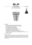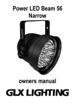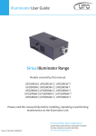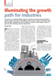
1
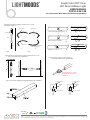
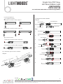
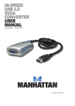
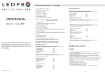
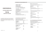
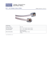
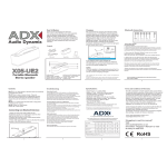
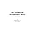
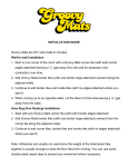
LightMoods
TM
Single Color TOP View LED Neon Ribbon Light
USER MANUAL
TOPSC-24V-108
(Green/Blue/Warm White/White/Cool White/Daylight White)
PLEASE READ THESE INSTRUCTIONS CAREFULLY BEFORE INSTALLATION AND LEAVE A COPY FOR THE END
USER/MAINTENANCE ENGINEER FOR FUTURE REFERENCE
FEATURES
WARNING AND CAUTION
1. Model: TOPSC-24V-108
2. Rated input voltage: DC 24V
3. Rated Power: 11W/m
4. Dimension: 16*16mm
5. LED quantity: 108 LEDs/mtr
6. LED Spacing: 9.3mm
7. Min. cutting length: 55.6mm( 6LEDs)
8. Max. running length for integral connector:
10 mtrs for single end feed or 20mtrs for double ends feed.
Max. running length for DIY connector:
10 mtrs for single end feed or 20mtrs for double ends feed.
9. Light color: Single Color
(Green/Blue/Warm White/White/Cool White/Daylight White)
10. Min. bent diameter: 300mm. Do not twist the light.
11. Protection rate: IP68
12. Protection rate for IP68: Protected against dust and submersion
in water (1meter above).
NOTE: All connector joints must be connected correctly
to achieve IP68 rating
13. Can be cut and extended (Only applicable to DIY accessories)
14. Long lifetime: 5 years
15.Working ambient temperature: -4°~113°F (-20°~45°C)
WARNING
1. Before making any cuts,installation,maintenance or connection, be sure
the mains is disconnected!
2. NOTE: ALL CONNECTOR JOINTS MUST BE CONNECTED CORRECTLY TO
ACHIEVE IP68 RATING.
3. Please operate this flex light according to the instructions, and confirm
the work voltage, it must be matched with product requirements.
4. Please confirm the polarity of connector before insertion front connection cable.
5. Connect and cut this product correctly. Any wrong operation will damage this
product.
6. No pressing on this product during storage, long term pressing may lead to damage.
7. Using qualified DC power supply.
8. Min. bent diameter 300mm, see Fig.1.
9. Do not twist the light as Fig.2 and follow the correct bending direction as Fig.3.
10. Do not hang this light in the air as Fig.4.
11. Cutting at the wrong location will result in a failure of the light! See Fig.5.
CAUTION
1. Suitable for mounting on normally flammable surfaces..
2. Use only factory-recommended connectors and accessories.
3. To ensure its long life span, operate the light properly in accordance with the
instructions.
4. Do not operate in more than 113°F (45°C) ambient temperature.
5. Assemble the DIY Connector correctly as in Fig.6.
6. Max. running length depends on the energizing way as Fig.7 shown.
7. Warm White,Cool White and Daylight color reference ANSI STANDARD.
8. Do not operate light when ambient temperature is below 32°F (0°C) thais may injure
the light .
16.Operating (bending) ambient temperature: 32°~113°F (0°~45°C)
ASSEMBLY AND INSTALLATION
ACCESSORIES (SOLD SEPARATELY)
1. Turn off the electricity before operation.
2. Cut the light at correct location (if need).
3. Assemble the light according to Fig.8.
4. Install U channel and light according to Fig.9 (Only applicable to DIY accessories) .
5. Wire all connectors to the power line and check wiring of the whole circuit.
Cable color coding basics Refer to Fig.10.
IP68 Clasp Type Accessories Kit
Single End Connection Application Accessories Kit
01 (or 02) Front Connector
Silicon Gasket
U Steel Plate
Anti-skidding Clip
FIGURES
Fig . 1 Minimum bent diameter 300mm
Clasp Front Connector Accessories Kit
1 pc
1 pc
1 pc
1 pc
Light Surface
Clasp End Cap Accessories Kit
1pc
1pc
1pc
1pc
The Tail Plug
U Steel Plate
Anti-skidding Clip
Silicon Gasket
Φ300mm
DO-160G
tested
Palm Coast, Florida, USA / Los Angeles, California, USA / Pribram, Czech Republic / Birmingham, U.K. / Kuala Lumpur, Malaysia / Mumbai, India
Email: [email protected] / Web: www.aveoengineering.com
LightMoods
Single Color TOP View
LED Neon Ribbon Light
TM
USER MANUAL
TOPSC-24V-108
(Green/Blue/Warm White/White/Cool White/Daylight White)
Twisting the light is forbidden and observe to correct
bending orientation
Light Surface
Light Surface
√
√
×
×
×
×
The correct cutting way,R= 90°
Light Surface
×
×
×
Wave cutting is incorrect
Light Surface
Light Surface
Recommenad Use
√
√
Fig . 2
R=90°is incorrect
Fig . 3
Fig. 4 Installation of the light hanging suspended in the air as
the picture illustrates is forbidden.
Fig.6 Correct insertion of connector pins
(Only applicable to DIY accessories)
×
×
Pay attention to”+” both
on light body and front
connector
Fig . 5 Unit cutting guide(Only applicable to DIY accessories)
Lighting surface
LED
PCB
Lighting surface
LED
PCB
Light Surface
Connector Pins
√
PVC
PCB
D
4
C2
Connector Pins
×
V
Cutting line
DO-160G
tested
2
Palm Coast, Florida, USA / Los Angeles, California, USA / Pribram, Czech Republic / Birmingham, U.K. / Kuala Lumpur, Malaysia / Mumbai, India
Email: [email protected] / Web: www.aveoengineering.com
LightMoods
Single Color TOP View
LED Neon Ribbon Light
TM
USER MANUAL
TOPSC-24V-108
(Green/Blue/Warm White/White/Cool White/Daylight White)
Fig.7 Energizing Method
① For integral connector:
①
Single ends connection for Max. length 5m
Diagram
Clasp Front Connector Assemble
Silicon Gasket
Anti-skidding Clip
Light
U Steel Plate
Front Connector
Double ends connection for Max. length 10m
Step
1.
2.
②
Anti-skidding Clip
No obvious gaps between bottom
and end of Anti-skidding clip and
light.
Silicon Gasket
For DIY connector:
3.
Single ends connection for Max. length 10m
4.
Double ends connection for Max. length 20m
Front Connector
Pins on the back of
PCB is correct.
Refer to Fig.6.
5.
Fig . 8 IP68 Clasp Type Connector Assemble
Diagram
Ligh
n
Fro
t Co
nne
ctor
Sili
con
Gas
co
Sili
t
n
k
Gas
T
et
l
ail P
he T
ug
6.
U Steel Plate
7.
ket
i-s
Ant
Ant
i-sk
ng
iddi
US
tee
DO-160G
tested
kidd
Clip
l Pla
ing
Clip
Push in using special wrench
US
tee
l Pla
te
8.
te
3
Palm Coast, Florida, USA / Los Angeles, California, USA / Pribram, Czech Republic / Birmingham, U.K. / Kuala Lumpur, Malaysia / Mumbai, India
Email: [email protected] / Web: www.aveoengineering.com
LightMoods
Single Color TOP View
LED Neon Ribbon Light
TM
USER MANUAL
TOPSC-24V-108
(Green/Blue/Warm White/White/Cool White/Daylight White)
② Clasp End Cap Connector
Fig . 9 Installation Guide
Assemble
Diagram
Anti-skidding Clip
Silicon Gasket
Light
U Steel Plate
The Tail Plug
Aluminum Profile Installation Guide
Step
Fixing Aluminum Profile
by screw
Install the light into the
aluminum Profile
Anti-skidding Clip
1.
Light
No obvious gaps between bottom
and end of Anti-skidding clip and
light.
2.
Silicon Gasket
Fig . 10 Cable color coding basics
3.
(+)
(-)
4.
The Tail Plug
5.
ANSI STANDARD
6.
U Steel Plate
7.
Push in using special wrench
8.
DO-160G
tested
Nominal CCT Categories
Nominal CCT
Target CCT and tolerance(K)
Target Duv and tolerance
2700K
3000K
3500K
4000K
4500K
5000K
5700K
6500K
2725 ± 145
3045 ± 175
3465 ± 245
3985 ± 275
4503 ± 243
5028 ± 283
5665 ± 355
6530 ± 510
0.000 ± 0.006
0.000 ± 0.006
0.000 ± 0.006
0.001 ± 0.006
0.001 ± 0.006
0.002 ± 0.006
0.002 ± 0.006
0.003 ± 0.006
Flexible CCT
(2700-6500K)
T 2 +ΔT 3
D UVT 2±0.006
4
Palm Coast, Florida, USA / Los Angeles, California, USA / Pribram, Czech Republic / Birmingham, U.K. / Kuala Lumpur, Malaysia / Mumbai, India
Email: [email protected] / Web: www.aveoengineering.com
LightMoods
TM
Single Color TOP View
LED Neon Ribbon Light
USER MANUAL
TOPSC-24V-108
(Green/Blue/Warm White/White/Cool White/Daylight White)
Remarks:
1. Six of the nominal CCTs correspond to those in the fluorescent
lamp specification [2]:2700K,3000K(Warm
White),3500K(White),4100K(Cool White),5000K and
6500K(Daylight),respectively.
2. T is chosen to be at 100K steps (2800,2900,…,6400K),
excluding, hose eight nominal CCTs listed in Table 1.
2
3. ΔT is given by ΔT = 0.0000108×T +0.0262×T+8.
4. Duv is given by Duv=57700×(1/T)2-44.6×(1/T)+0.0085
GUARANTEE
1. We provide lifelong technical assistance with this product:
A 3 year warranty is given from the date of original purchase.
The warranty is for free repair or replacement and covers manufacturing
faults only.
For faults beyond the 3 year warranty we reserve the right to charge for
time and parts.
Current technology will be selected first for repair or replacement.
2. Warranty excludes below:
Any man-made damages caused from improper operation, assembly,
wiring, connection, installation, transport and storage.
Improper input voltage, current, operating and working environment.
The product appears to have excessive physical damage.
Damage due to natural disasters and force majeure.
Product label or data code have been damaged.
3. Repair or replacement as provided under this warranty is the exclusive
remedy to the customer.
We shall not be liable for any incidental or consequential damages for
breach of any stipulation in this warranty.
4. Any amendment or adjustment to this warranty must be approved in
writing by us only.
5. This manual only applies to this model. We reserves the right to modify
the manual and keep the right to make final edition of this manual.
DO-160G
tested
5
Palm Coast, Florida, USA / Los Angeles, California, USA / Pribram, Czech Republic / Birmingham, U.K. / Kuala Lumpur, Malaysia / Mumbai, India
Email: [email protected] / Web: www.aveoengineering.com