1
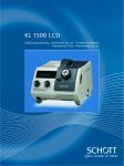
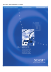
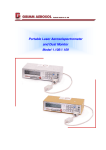
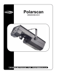
FIBER OPTICS
COLD LIGHT SOURCES
KL 2500 LCD
Gebrauchsanweisung
Instructions for use
Conseils d’utilisation
Istruzioni per l’uso
Instrucciones de uso
USER MANUAL KL 2500 LCD
For recycling information please visit
www.schott.com/fiberoptics/recycle
KL 2500 LCD
9
5
15
6
14
12
4
3
2
7
10
11
13
1
17
16
8
18
19
Übersicht LCD-Anzeige
Overview of the LCD display
Vue d’ensemble de l’affichage LCD
Display a cristalli liquidi
Detalle de la visualización por cristal líquido
20
21
22
Instrument overview
1
Mains electricity switch
2.2
2
Light guide connection
2.1
3
Electronic light intensity setting
2.3
4
Mechanical light intensity setting
2.3
5
LCD display
6
Lever for supplementary optics
2.4
7
Filter wheel
2.5
Connection socket for remote operation and/or
inclination angle switch
2.6
8
9
13
Carrying handle
10
Lamp compartment with halogen cold light reflector lamp
3
11
Button lamp compartment
3
12
Mains cable
13
Ventilation opening (front of instrument)
1
14
Ventilation opening (side of instrument)
1
15
Air outlet grill (back of instrument)
1
16
Fuse (base of instrument)
5
17
Model plate (base of instrument)
18
Color temperature display
2.3
19
Fault status display
5
20
Indication of maximum light intensity
2.3
21
Indication of “STAND-BY” Modus
2.6
22
Indication of connected remote control
2.6
1 Important information
Symbols used:
Warning of danger
(caution, obey documentation)
Warning of a hot surface
Instrument of Protection Class II
Off (disconnected from mains)
On (connected to mains)
Indication of maximum light
intensity
Intended use:
The cold light source KL 2500 LCD
is intended for industrial and laboratory
applications.
Cold light sources are used for the
intensive illumination of all types of
objects. The infrared components in
the lamp radiation are filtered out.
High intensity visible light is guided to
the object through flexible or selfsupporting, movable light guides. The
unit is tested and certificated to the
applicable standards on electrical laboratory equipment (DIN EN 61010-1 and
UL 3101-1) and to the standard on
medical electrical equipment
(EN 60601-1 and UL 2601-1).
➧ Never cover up the open clamping
sleeve or the light guide exit
(danger of fire).
➧ Never cover up the open clamping
sleeve or the light guide exit with
your hand or other part of the body
(danger of burns).
➧ When illuminating heat-sensitive or
flammable light-absorbing objects
(e.g. in microscopy), special care
must be taken to ensure that a suitable light guide separation distance
and lamp brightness are chosen so
that no thermal damage occurs.
➧ the lamp has cooled down before
it is changed; to remind you, a
warning symbol is attached to
the lamp compartment door:
GB
(warning of hot surface);
➧ the filter wheel has cooled down
before being removed. It carries
the warning symbol;
➧ the light source is operated exclusively with the filter wheel inserted.
The filter wheel must always be in
one of the five locking positions.
■ The light source has been developed
➧ When the light source is switched
on, all light guide exits not being
used in the working procedure must
always be at a safe distance – at least
10 cm – from heat-sensitive or
flammable light-absorbing materials
(prevention of possible danger of
fire). Therefore take care that each
light guide exit is at the above safe
distance from, for example, dark/
colored textiles and dark/colored
wood or plastics surfaces.
➧ To avoid unnecessary stressing of
biological tissue by illumination with
visible light, reduce the brightness
and duration of illumination
to the absolute minimum required
level.
for operation in dry rooms only
(see point 7 “Technical Data”).
■ Contact with cleaning solvents and
desinfectants as well as oils and
oil/air mixtures can induce tension
cracks in the light source body.
Therefore direct contact with these
substances must be absolutley
avoided.
■ This instrument is not suitable for
operation in areas where there is
an explosion hazard.
■ Safe disconnection from the power
supply takes place also by pulling
out the mains plug.
■ The instrument must not be opened
Safety information:
Please read and obey these instructions carefully. The instrument’s
safety cannot be guaranteed if they
are not obeyed.
Avoid looking directly into the open
clamping sleeve or the light guide exit
when the light source is switched on.
The KL 2500 LCD emits high-intensity
visible light. Because light-absorbing
materials have the physical property
of converting incident light into heat,
damage can occur to heat-sensitive or
flammable light-absorbing materials.
To avoid such thermal damage and
the potential danger of fire or burns,
please obey the following instructions:
It is absolutely essential that you
ensure that:
➧ your KL 2500 LCD light source is
operated at the voltage stated on
the model plate (17);
➧ all ventilation openings (13, 14, 15)
are kept free. In the event of insufficient cooling, a built-in thermostatic
switch switches the instrument off
temporarily (see point 5 “Troubleshooting”);
or dismantled. Technical modifications to the instrument are
forbidden. Repairs must be carried
out only by the manufacturer or
by its authorised customer
service agencies.
■ Please ensure that every user of the
instrument has quick access to these
instructions.
■ The manufacturer is not liable for
damage caused by failure to obey
these instructions.
➧ the lamp has cooled down before
it is changed; to remind you, a
warning symbol is attached to
the lamp compartment door:
(warning of hot surface);
14
2 Operation
2.1 Light guide connection
2.2 Start-up procedure
2.3.1 Electronic adjustment
First open the light guide socket (2) by
turning the outer black ring in a counter-clockwise direction. To connect
light guides with an 18 mm sleeve diameter, remove the socket adapter. Push
the light guide in as far as the stop and
close the light guide socket.
Switch on/off by operating the mains
switch (1).
The brightness can be adjusted steplessly by turning the light intensity setting knob (3).
There are four distinct notched positions between the two end positions
of the adjusting knob. These fixed positions, thus ensure the reproducibility of
pre-selected brightness settings.
Position :
The instrument is switched off.
Position I :
The instrument is switched on.
To protect the halogen lamp the
KL 2500 LCD is fitted with a gentle
start-up device that reduces the
high switch-on current that would
otherwise occur. In addition, electronic
stabilisation of the lamp voltage
ensures stable light power regardless
of fluctuations in the mains voltage.
▼
▼
▼
Caution:
When inserting light guides with a
location pin, care must be taken to
ensure that the latter fits into one of
the four clamping clip slots.
Position 1 gives the lowest light intensity, and maximum brightness is attained in position 6. The two barriers
at positions 4 and 5 are bypassed by
pressing in the adjustment knob.
The socket adapter becomes hot
during operation. Please ensure that it
has cooled down before removal.
2.3 Light intensity setting
The adjustment knob cannot be turned beyond the end stops 1 and 6
respectively.
The KL 2500 LCD is fitted with two
independent alternative means to
adjust the light intensity.
The lamp lifetime in position 4 is about
1500 hours and in position 5 it is
about 150 hours.
The stepless electronic adjustment
enables you to optimise the lamp
lifetime - by precisely setting the
brightness you require, you will
achieve the longest halogen lamp
lifetime that is possible for your
application. This also varies the color
temperature of the emitted light.
In position 6 the halogen lamp is
operated at its nominal voltage and
the lamp will achieve approximately
the rated lifetime stated by the lamp
manufacturer (depends upon
the type).
▼
To remove the adapter, first of all completely unscrew the black ring. Then
slightly press the adapter together at
the positions marked
and remove it.
Insertion of the adapter takes place in
the reverse sequence.
The mechanical adjustment enables
stepless variation of the light intensity
at a constant color temperature.
15
The approximate color temperature of
the light emitted by the halogen lamp
(18) is indicated on the LCD display (5).
The color temperature of the light can
be set by turning the light intensity
adjustment (3) (step width 50 K).
After bypassing the barrier at position 5,
a lamp symbol (20) appears in the LCD
display and flashes for the first few
seconds. This acts as a maximum light
indication and gives a warning that the
expected lamp lifetime will be reduced
compared to position 5.
2.3.2 Mechanical aperture
2.4 Supplementary optics
The light intensity can be altered
steplessly while retaining the color
temperature by turning the adjustment
knob of the mechanical aperture (4).
Two fixed end-stops and three
additional retention points (marked
with the letters A to E) enable defined
aperture settings to be selected
reproducibly.
Use of the supplementary optics
ensures that uniform, high-intensity
illumination is achieved even when
using light-guides with a smaller
bundle diameter.
▼
GB
If the illumination is carried out with
imaging or focussing optical systems at
the light guide exit, optimally uniform
illumination is achieved by moving the
supplementary optics out of the optical
path.
Position - Supplementary optics in
optical path:
uniform illumination with no optical
systems at the light guide exit.
▼
Position - Supplementary optics out
of optical path:
uniform illumination with optical
systems at the light guide exit.
The supplementary optics must always
be positioned at the end stop.
Position A gives the lowest brightness,
and maximum brightness is achieved
in position E (aperture completely
open). Turning the adjustment knob
from one retention point to the next
approximately doubles or halves the
light intensity respectively each time.
▼
The adjustment knob cannot be
turned beyond the end-stops A and E
respectively.
16
2.5 Filter wheel
2.5.1 Fitting the Filter
2.6 Remote control connection
The KL 2500 LCD has a filter wheel (7)
which can be fitted with a maximum
of 5 filters.
Please ensure the light care to ensure
that the light source is switched off and
has cooled down before removing the
filter wheel.
There is a warning symbol
to
remind you.
A remote control and/or inclination
angle switch (accessories) can be
connected to the light source via the
connection socket (8).
Different color and fluorescence
excitation filters (available as accessories) can be brought into the optical
path by turning the ridged edge of the
filter wheel.
Please ensure that the filter wheel is
always engaged in one of the predefined
rest positions.
Operating the light source with the
filter wheel in an intermediate position
can cause the wheel to overheat.
The ridged edge of the filter wheel has
position markings (the corresponding
number of raised marks identifies positions 0 to 4).
▼
▼
To remove the filter wheel, take hold in
the depression on the underside of the
carrier, pull it out to the stop, lift slightly
and then carefully remove.
To fit filters into the wheel, remove
the cross-head screw and remove the
plate holding the filter in place.
Insert the filter into the wheel. Push on
the plate and tighten the screw. Insert
the filter wheel into the guide and push
it into the cold light source until it
engages.
Please ensure that your KL 2500 LCD
is operated exclusively with the existing
filter wheel. This is the only way to
guarantee optimum air cooling of the
light source.
The indication “REMOTE” (22) appears
in the LCD display when the remote
control is plugged in.
The remote control can electronically
set the light intensity, thus putting the
light intensity control knob (3) temporarily out of operation.
Both the remote control and the
inclination angle switch provide a
facility to put the light source into
“STAND-BY” mode to protect the
halogen lamp. A corresponding indication (21) appears in the display.
▼
Please note the following:
17
In “STAND-BY” mode the appliance is
not disconnected from the mains electricity supply. The remote control (or
the inclination angle switch) should
only be connected and disconnected
when the appliance is switched off.
3 Replacing the lamp
4 Maintenance
5 Troubleshooting
Please ensure that the lamp and lampholder have cooled down before
replacement. The corresponding
warning symbol is attached to remind
you.
Your KL 2500 LCD is maintenance-free.
The display has a fault status indicator
(19). Any possible breakdowns can be
recognized quickly and easily.
▼
To clean the outside of the instrument,
use a soft dry cloth or commercially
available plastic cleaning cloths.
Contact with cleaning solvents and
desinfectants as well as oils and oil/air
mixtures can induce tension cracks in
the light source body. Therefore direct
contact with these substances must be
absolutley avoided.
GB
„Err 1“: Lamp circuit interrupted.
„Err 2“: Temperature monitor has
triggered.
„Err 3“: Short-circuit in the lamp
circuit, electronic fuse has
triggered.
▼
First of all switch off the light source.
Open the lamp compartment (10) by
pressing the button (11) and pull it out
as far as the stop.
Press down the two levers of the special socket and pull out the faulty lamp.
The two levers must be pressed down
again while inserting the new lamp.
Push the lamp compartment in until
it latches (audible locking sound).
Switch the light source on.
Fault
Possible causes
Remedial action
Lamp out,
fan not running,
no LCD display
Instrument not switched on.
Switch instrument on.
Plug not in socket.
Plug the plug in.
No mains electricity voltage.
Check mains voltage.
Lamp compartment not closed.
Close lamp compartment.
Fuse faulty.
Replace fuse (16).
Transformer overheated.
Ensure adequate cooling, check
that lamp type is correct, re-start
instrument after cooling down for
a prolonged time.
Remote control or
inclination angle switch faulty.
With instrument switched
off, disconnect accessories
Lamp out,
fan running,
fault status indication
„Err 1“
Lamp defective.
Replace lamp (see point 3
of these instructions).
No lamp.
With light source switched
off, install lamp.
Lamp out,
fan running,
fault status indication
„Err 2“
Insufficient cooling.
Ensure ventilation apertures are
free, avoid excessive ambient
temperatures, the instrument will
switch back on again after a
short time.
Lamp out,
fan running,
fault status indication
„Err 3“
Transient current increase
in lamp circuit.
Switch instrument off and, after
a few seconds, back on again.
Lamp causing short-circuit.
Replace lamp (see point 3
of these instructions).
If you are unable to rectify the fault by the actions mentioned above, please contact
your specialist dealer or the nearest SCHOTT agency. More extensive repairs must
be carried out by the authorised customer service depot.
18
6 Accessories
A wide range of accessories is available
for your KL 2500 LCD. A separate brochure gives you comprehensive
information – to get it see addresses
overleaf.
Only SCHOTT light guides and accessories guarantee perfect operation,
safety and optimum light yield.
6.4 Remote control
6.5 Inclination angle switch
The following functions can be controlled by remote control:
The inclination angle switch switches
the light source into the “Light on”
or “STAND-BY” modes depending on
its angle of inclination relative to the
ground. Inclination angle switches are
mounted, for example, on the freely
mobile arm of diagnosis microscopes.
Both the remote control and the
inclination angle switch have a connection cable 3 m long as standard.
A cable splitter enables a remote control and inclination angle switch to be
operated simultaneously. Please consult
the instructions enclosed with the respective device for detailed information
on the remote control and inclination
angle switch.
• Light on/off (“STAND-BY”)
• Electronic light intensity adjustment
6.1 Light guides
Self-supporting and flexible light guides in various lengths and diameters
are available, as well as point and slit
illuminators.
6.2 Halogen lamps
When ordering halogen lamps as spare
parts (see point 6.6 of this instruction),
the lamp type that enables optimum
light yield and illumination will be supplied.
6.3 Filters
Optical filters can either be inserted
into the filter wheel (7) or placed in
front of the light guide exit as a screwin or push-on filter in conjunction with
an auxiliary focussing device (accessory). Details of the auxiliary focussing
device and the filter types available as
standard can be found in the accessories catalogue.
6.6 Spare parts
Spare part
Catalogue No.
Halogen lamp 24 V/250 W
Osram, type HLX 64653
Philips, type 13163
253 000
Fuse for 230 V (primary)
T 3,15 H, 250 V acc. to IEC 127-3/5
253 101
Fuse for 120 V (primary)
M 6,3 A acc. to UL 198 G
253 103
To ensure maximum performance, light yield and safety you must only use the spare parts
stated above.
7 Technical data
Properties
Values
General information
Type description
Dimensions (W x D x H)
mm
Weight
kg
Cooling
-
KL 2500 LCD
approx. 200 x 265 x 170
approx. 6
axial (fan cooled)
Ambient temperature*
°C
+ 5 ... + 40
Relative air humidity*
%
at 31°C ambient temperature: 85 %
from 31°C to 40°C ambient temperature:
decreasing linearly to 75 %
Air pressure*
hPa
700 ... 1060
Transport and storage
Temperature
Rel. air humidity
Air pressure
°C
%
hPa
- 40 ... + 70
10 ... 95 (non-condensing)
500 ... 1200
Contamination level
-
2
* Test conditions of Standards DIN EN 61010-1, DIN EN 60601-1 and UL 3101-1.
continued on page 20
19
Properties
Values
Electrical information
GB
Operating voltage,
frequency
230 V version
120 V version
220 ... 240 V ~ 50 / 60 Hz
100 V ~ 50 / 60 Hz and
120 V ~ 60 Hz
± 1.5 % of the set lamp
voltage (true RMS value)
Electronic stabilisation of the lamp
voltage (working range: specified
operating voltages ± 10 %)
Power consumption, max.
W
300
230 V version
-
120 V version
-
T 3,15H,250 V in accordance with
IEC 127-3/5
M 6,3 A in accordance with UL198 G
Protection class
-
II
Overvoltage category
-
II
Lamp type
-
Halogen reflector lamp
Osram, type HLX 64653
Philips, type 13163
Lamp rated voltage
V
24
Lamp rated power
W
250
Average lamp lifetime
Level 4
Level 5
Level 6
h
h
h
1500
150
50
Fuses, primary
Lighting information
Maximum effective
light guide bundle diameter
Total light flux at light guide exit
(SCHOTT light guide, Ø 15 mm, typ. values)
Level 4
Level 5
Level 6 (max. light flux)
Light entry angle (2αeff)
Without supplementary optics
mm
lm
lm
lm
degrees
Heat protection filter
-
Approvals
230 V version
120 V version
-
15
500
1000
1300
approx. 53
SCHOTT KG 2, 45 x 45
thickness = 2,0 mm, toughened
The KL 2500 LCD has been tested and certificated to the applicable standards on electrical
laboratory equipment (EN 61010-1 and UL 3101-1) and to the standard on medical electrical
equipment (EN 60601-1 respective UL 2601-1). This enables manufacturers to obtain easy
approval with integration of the KL 2500 LCD into their medical products.
Die 230 V version features
.
The right is reserved to make changes in the design and supplied items within the scope of on-going technical
development.
20