1
Market Central, Inc.
4. Installation
1.
2.
3.
4.
5.
6.
7.
8.
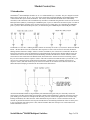
Find a location suitable for installing the R6100 chassis, with access to AC power outlets and the connections
you intend to switch through the unit.
During initial installation, the R6100 should first be powered up and the connection state should be switched
between “A” and “B” using the keylock switch and front panel toggle switch. This insures that all of the
internal relays or fiber optic switch mechanisms (depending on model) are in a known connection state before
attaching network cables to the unit. Because the R6100 uses latching relays and latching fiber optic
switching mechanisms, as soon as cables are attached, the selected data paths will be active regardless of
whether or not the R6100 is powered ON. Once this step has been completed, remove power from the R6100
until after all other connections have been made as described below.
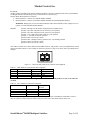
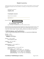
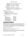
If you intend to use serial control, connect a serial cable to the DB9 RS232 console port. If the R6100 has the
Ethernet Module installed, set the terminal to 9600 baud, no parity, 8 data bits, and 1 stop bit. If the R6100
does NOT have the Ethernet Module installed, set the terminal to 1200 baud, no parity, 8 data bits, and 1 stop
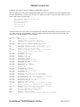
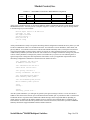
bit. See table 3.1 for the DB9 connector signal assignment.
Connect a 12VDC power supply to either power supply connector. If you are using redundant power
supplies, connect one to each power supply connector. The indicators, PS1 and PS2 on the front of the unit
will indicate that the associated power supply is energized.
Connect RJ45 or fiber optic cables between the R6100 unit and the devices/network connections that you
want to control. R6100 Gang Switches connect the COMMON ports to either A ports or B ports. For R6100
Sharing Switch models, Shared Port B is connected to the selected Device Port, and all other Device Ports are
connected to their respective A Ports.
The R6100 switches are completely bidirectional, and have no preference to signal direction. Note that the
switch provides straight pass thru connections. If your application requires a cross-over cable, use only 1
cross-over cable in that path. Use a straight through cable on the other side of the switch.
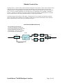
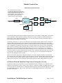
If you are daisy-chaining multiple racks together to create a system of racks, connect an RJ11 crossover cable
from the GANG OUT port on one unit to the GANG IN port on the next unit. Note that only the first rack in a
daisy chain system can have an Ethernet remote interface option installed (models with the “R” designator at
the end of the model number), all the rest of the racks in that daisy chain must be non-Ethernet models. Also,
if the first rack does have an Ethernet remote interface option, its address DIP switch must be set to address 1,
and the address DIP switches of the other racks in the daisy chain must each be set to a unique address in the
range from 2 to 255.
Apply AC power to (each) power supply. The appropriate power supply status indicators (PS1 and/or PS2)
will light. The switch position indicators (A and B) on the front of the unit may or may not light depending
on the position of the switch ports. Indicator A lights only when all ports are in position A, and likewise
indicator B only lights when all ports are in position B.
NOTE: If you are connecting the R6100 (network manageable model) to an Ethernet network, you must first set
some TCP/IP related parameters using the serial port on the R6100. You should set these parameters before
attaching a cable to the NETWORK port, as the default parameters may not work or could interfere with your
network. See section 5.4 for more information regarding TCP/IP setup.
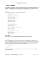
5. Operation
The R6100 contains 4, 6, 8 or 16 switch circuits (ports) depending on model. When power is applied to the R6100
unit, the appropriate power supply status indicators (PS1 and/or PS2) will light. The switch position indicators (A
and B) on the front of the unit may or may not light depending on the position of the switch ports. Indicator A lights
when all ports are in position A (each A port from “1” to “N” is connected to its respective COMMON port “1” thru
“N”), and likewise for indicator B. If some switch ports are in position A and some in position B then neither LED
will be on.
There are two status indicators which function as follows. The LINK LED is turned ON when the internal processor
has finished initialization. Note that it does not indicate that a valid network connection is made. The ACT LED
will blink whenever the internal processor receives a command from the internal Ethernet module (on network
manageable models) or from an upstream rack in a daisy-chained system of racks.
SwitchMaster® R6100 Multiport Switches
Page 6 of 30