1
[INSTALLATION PRECAUTIONS]
CAUTION
High Speed Counter Module
Type A1SD61
1. GENERAL DESCRIPTION
z Do not directly touch the conducting part of the module.
Failure to observe this instruction will cause the module to malfunction or break
down.
z Install the module by engaging the module mounting projections on the lower part
of the module in the mounting holes of the base unit. Incorrect installation could
result in malfunctions, failure of detachment.
This manual describes specifications, handling and wiring of an A1SD61 high speed
counter module (hereinafter referred to as the A1SD61).
2. PERFORMANCE SPECIFICATIONS
Item
Counting speed selection
pin
Number of occupied I/O
points
Number of channels
Phase
Count
input
Signal levels
signal
( A and B)
[WIRING PRECAUTIONS]
CAUTION
User’s Manual
(Hardware)
Thank you for buying the Mitsubishi general-purpose programmable
logic controller MELSEC-A Series
Prior to use, please read both this manual and detailed manual
thoroughly and familiarize yourself with the product.
MODEL
A1SD61 (H/W)-U-E
MODEL
13JE47
CODE
IB(NA)-66486-C(1112)MEE
z The twisted shielded wire must be grounded to at least class 3 specifications at
the encoder side (relay box).
z Ground the AG terminal using third class grounding or higher exclusively for the
PC. If you do not, the PC will malfunction.
z Before connecting wires to the PC, check the rated voltage and the terminal
arrangement. Connecting power of a different voltage or wiring incorrectly will
result in fire or failure.
z Do not apply the voltage higher than the value set with a jumper. Failure to
observe this instruction will result in failure.
z Tighten the terminal screws to the specified torque.
Loose terminal screws will cause a short, fire or malfunctions.
Tightening the terminal screws too far may cause damage to the screws resulting
in short circuits or malfunctions.
z Take all possible measures to prevent chips or wire scraps from entering the
module. Entry of foreign material will cause fire, failure of malfunctions.
z Do not touch the terminals while they are live. This will cause malfunctions.
z Switch the power off before cleaning the module or retightening the terminal
screws. If the power is left on, the module will break down or malfunction.
Before using this product, please read this manual and the relevant manuals
carefully and pay full attention to safety to handle the product correctly.
These precautions apply only to Mitsubishi equipment. Refer to the CPU module
user’s manual for a description of the PC system safety precautions.
In this manual, the safety precautions are classified into two levels:
"
WARNING" and "
CAUTION".
WARNING
Indicates that incorrect handling may cause hazardous
conditions, resulting in death or severe injury.
CAUTION
Indicates that incorrect handling may cause hazardous
conditions, resulting in minor or moderate injury or
property damage.
Under some circumstances, failure to observe the precautions given under
"
CAUTION" may lead to serious consequences.
Observe the precautions of both levels because they are important for personal
and system safety.
Make sure that the end users read this manual and then keep the manual in a
safe place for future reference.
[DESIGN PRECAUTIONS]
WARNING
z Failure of external output transistors could cause outputs to remain
continually ON or continually OFF.
Provide an external circuit to monitor output signals whose disruption could
cause serious accidents.
CAUTION
z Use the programmable controller in an environment that meets the general
specifications in the user’s manual for the CPU module used.
Using it in an environment which does not meet the general specifications
could cause electric shock, fire or malfunctions, and damage or deterioration
of the module.
z Do not bundle the control wire and the communication cable with the main
circuit or power line or keep them close to one another.
Keep the control wire and the communication cable at least 150 mm away
from the main circuit or power line: otherwise, noise or malfunctions will
occur.
Limit
switch
output
CAUTION
z Do not disassemble or tamper with the module. This will cause failure,
malfunctions, injuries or fire.
z Switch the power off before installing or removing the module. If the power is left
on, the module will break down or malfunction.
[DISPOSAL PRECAUTIONS]
(Read these precautions before using this product.)
Type
Counter
[STARTING AND MAINTENANCE PRECAUTIONS]
WARNING
©1994 MITSUBISHI ELECTRIC CORPORATION
zSAFETY PRECAUTIONSz
Maximum
counting
speed
Counting
range
CAUTION
z CONDITIONS OF USE FOR THE PRODUCT z
External
input
External
output
About This Manual
The following manuals are also related to this product.
In necessary, order them by quoting the details in the tables below.
Detailed Manual
Manual Name
High speed counter module type A1SD61
User's Manual
Manual No.
(Type code)
IB-66337
(13J674)
32
1
1-phase and 2-phase inputs
5 VDC
12 VDC
2 to 5 mA
24 VDC
1-phase input
50k pps
10k pps
50k pps
7k pps
*1 2-phase input
32-bit binary
-2147483648 to 2147483647
Equipped with UP/DOWN preset counter and ring
counter functions
Unit: s
Unit:
Specific isolated
area
z Dispose of the module as industrial waste.
Notwithstanding the above, restrictions Mitsubishi may in its sole discretion, authorize use of the
PRODUCT in one or more of the Prohibited Applications, provided that the usage of the
PRODUCT is limited only for the specific applications agreed to by Mitsubishi and provided
further that no special quality assurance or fail-safe, redundant or other safety features which
exceed the general specifications of the PRODUCTs are required. For details, please contact
the Mitsubishi representative in your region.
10K side
Minimum
s
count pulse
20
100
142
width
Set input rise
and fall times
71 71
50 50
10
10
or
to 5
less. Duty
(1-phase and 2-phase
(1-phase
(2-phase
ratio: 50%
input)
input)
input)
Comparison
32-bit binary
range
A contact operation: Dog ON address < Count value <
Dog OFF address
Comparison
B contact operation: Dog OFF address < Count value <
result
Dog ON address
Preset
12/24 VDC 3/6 mA
Function start 5 VDC 5 mA
Coincidence
Transistor (open collector) output
output
12/24 VDC 0.1 A/point 0.8 A/common
(1) Mitsubishi programmable controller ("the PRODUCT") shall be used in conditions;
i) where any problem, fault or failure occurring in the PRODUCT, if any, shall not lead to any
major or serious accident; and
ii) where the backup and fail-safe function are systematically or automatically provided outside
of the PRODUCT for the case of any problem, fault or failure occurring in the PRODUCT.
(2) The PRODUCT has been designed and manufactured for the purpose of being used in general
industries.
MITSUBISHI SHALL HAVE NO RESPONSIBILITY OR LIABILITY (INCLUDING, BUT NOT
LIMITED TO ANY AND ALL RESPONSIBILITY OR LIABILITY BASED ON CONTRACT,
WARRANTY, TORT, PRODUCT LIABILITY) FOR ANY INJURY OR DEATH TO PERSONS OR
LOSS OR DAMAGE TO PROPERTY CAUSED BY the PRODUCT THAT ARE OPERATED OR
USED IN APPLICATION NOT INTENDED OR EXCLUDED BY INSTRUCTIONS,
PRECAUTIONS, OR WARNING CONTAINED IN MITSUBISHI'S USER, INSTRUCTION
AND/OR SAFETY MANUALS, TECHNICAL BULLETINS AND GUIDELINES FOR the
PRODUCT.
("Prohibited Application")
Prohibited Applications include, but not limited to, the use of the PRODUCT in;
y Nuclear Power Plants and any other power plants operated by Power companies, and/or any
other cases in which the public could be affected if any problem or fault occurs in the
PRODUCT.
y Railway companies or Public service purposes, and/or any other cases in which
establishment of a special quality assurance system is required by the Purchaser or End
User.
y Aircraft or Aerospace, Medical applications, Train equipment, transport equipment such as
Elevator and Escalator, Incineration and Fuel devices, Vehicles, Manned transportation,
Equipment for Recreation and Amusement, and Safety devices, handling of Nuclear or
Hazardous Materials or Chemicals, Mining and Drilling, and/or other applications where there
is a significant risk of injury to the public or property.
Specifications
50K side
Isolation specifications
Isolation
method
Dielectric
Insulation
withstand
resistance
voltage
Between pulse
input terminal
and PLC power
supply
Between preset
input terminal
and PLC power
supply
Photocou 500V
AC/1
Between function pler
isolation minute.
start input
terminal and PLC
power supply
Between
coincidence
output terminal
and PLC power
supply
or
5M
more by
500V DC
insulation
resistance
tester.
0.75 to 1.5 mm2
Applicable wire size
Applicable solderless
R1.25-3, 1.25-YSA, RAV1.25-3, V1.25-YS3A
terminals
Internal current
0.35 A
consumption (5 VDC)
Weight kg (lb)
0.27 (0.59)
*1: The counting speed is influenced by the pulse leading edge/fall time.
The following counting speeds are possible. If a pulse is counted with a leading
edge/fall time that is too long, a counter error may be caused.
Counting
Speed
50k
10k
Setting Pin
Leading
1-phase 2-phase 1-phase 2-phase
Edge/Fall
input
input
input
input
Time
t=5 s
t
t
50k pps
50k pps
10k pps
7k pps
or less
t=50 s
5k pps
5k pps
1k pps
700 pps
or less
—
—
500 pps 250 pps
t=500 s
Refer to the User’s Manual of the programmable controller CPU for the general
specifications.
5. WIRING
A1SD61
1)
5)
A
50K
10K
5V
12V
24V
2)
2
3
4
5
6
7
8
B
5V
12V
24V
1
A
6)
7)
8)
3)
1
RUN
A
B
PRESET
FUNCTION
2
B
4
PRESET
6
F.START
8
5V
12V
24V
1
L
2
3
4
5
9)
4)
6
7
8
+
-
COM
10
12
14
16
18
3
5
7
9
11
13
15
17
19
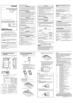
NO.
20
(1)
(2)
(3)
(4)
(5)
(6)
(7)
(8)
(9)
Name
Description
Counting speed selection Counts pulses at a maximum speed of 50k
pin
pps in 1-phase or 2-phase input.
Counts pulses at 10k pps in 1-phase input, at
50K
7k pps in 2-phase input. (The factory-setting is
10K
50k.) (Set with the jumper)
Input pulse voltage
Select a pulse voltage that is input to Phase A
selection pin
or B.
(The factory-setting is 24 V.)
A
B
The module operation cannot be guaranteed
5V
5V
12V
12V
when the pulse voltage higher than the set
24V
24V
value is applied.
(Set with the jumper)
External input voltage
Select a voltage input to the
selection pin
PRESET/F.START terminals.
(The factory-setting is 24 V.)
5V
The module operation cannot be guaranteed
12V
when the voltage higher than the set value is
24V
applied.
(Set with the jumper).
Used for protecting outputs 1 to 8 from
Fuse
overcurrent. (Circuit board soldering type)
Lit when the module operates normally.
Flashes when a data write error has occurred.
RUN
OFF when a watchdog timer error has
occurred.
Lit when voltage is applied to phase A pulse
A
input terminal.
Lit when voltage is applied to phase B pulse
B
input terminal.
LED
Lit and latched when voltage is applied to the
indicators
PRESET terminal.
PRESET
OFF when external preset detection reset
signal (Y16) is turned ON.
ON when voltage is applied to the F.START
FUNCTION
terminal.
ON when a corresponding limit switch is
OUTs 1 to 8 turned ON by he limit switch output function.
OFF when the limit switch is turned OFF.
Pulse input terminals ( B is used as
A/ B
decrement count command.)
The terminal in which voltage is applied when
PRESET
a preset is executed from an external device.
The terminal in which voltage is applied when
F. START
a counter function selection is executed.
An external output terminal used for limit
OUTs 1 to 8
switch output.
4. LOADING AND INSTALLATION
4.1 Cautions on Handling
(1) The case of the A1SD61 is made of resin: do not drop it or subject it to
strong impact.
(2) Do not remove the printed circuit board from the case. This could cause
failure.
(3) Make sure that no wire offcuts or other debris enters the top of the module
during wiring. If anything does enter the module, remove it.
(4) Tighten the module mounting and terminal screws as specified below:
Screw
Module mounting screw (M4 screw)
Terminal block terminal screw (M3.5 screw)
Terminal block mounting screw (M4 screw)
Tightening Torque Range N·cm
[kg·cm] (lb·inches)
78 to 118 [8 to 12] (6.93 to 10.4)
59 to 88 [6 to 9] (5.19 to 7.8)
78 to 118 [8 to 12]
A1SD61
5.1 Wiring precautions
Wire a pulse generator to the A1SD61 while paying attention to the followings;
(1) For a high-speed pulse input, take the following counter measures against
noise;
(a) Be sure to use shielded twisted pair cables. Also, make sure they are
grounded to the earth.
(b) Do not run a twisted pair cable in parallel with power cables or other I/O lines
which may generate noise.
Run cables at least 150 mm (5.91in.) away from the above-mentioned lines
and over the shortest distance possible.
(2) For 1-phase input, connect count input signal to phase A only.
(3) If the A1SD61 picks up pulse noise, it will count incorrectly.
(4) The specific measures against noise are shown below;
DC12/24V
0.1A
A1SD61
AISD61
PC
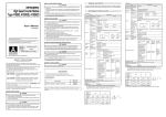
6. OUTSIDE DIMENSIONS
POINT
The encoder signal and supply lines should be wired as shown below:
The method for wiring a pulse generator to the A1SD61 is described here.
OUT
CORRECT
A1SD61
RUN
OUT
φA
φA
φA
φB
PRESET
FUNCTION
+24V Encorder
0V
E
+
External power supply
A1SD61
INCORRECT
OUT
Since the same twisted pair wire
is used for both the encoder
+24V Encorder signal and the power supply,
a reduction in the cancelling
0V
effect and electromagnetic
E
induction may occur.
φA
φA
+
External power supply
130 (5.1)
3. NOMENCLATURE
REMARK
* : Set the pulse input voltage setting pin to the
position.
(2) Connection of a voltage output pulse generator (5 VDC)
Inverter
A1SD61
Terminal
block
Terminal
block
470Ω1/4W
*1
Pulse input voltage
setting pin*
2.2kΩ
1/4W
Separate more
than 150 mm from
equipment such
as inverters. (Also
take care of wiring
inside the panel)
4.7kΩ1/4W
1/4W
4.7kΩ1/4W
V WE
Pulse input voltage
setting pin*
Twisted pair wire
φB
OUT
GND
*2
AC
motor
Carrier
REMARK
* : Set the pluse input voltage setting pin to the
(1) When a controller (sink load type) is supplied with 12 V:
A1SD61
680Ω 1/4W
4.7kΩ 1/4W
+24V
To φA
position.
5.3 Wiring Example for the Connection of a Controller to External Input
Terminals (PRESET and F.START)
(This is a connection example for 24 V send load)
To encorder
φA
0V
External input voltage setting pin*
y Ground twisted shielded wire on the encoder side (joint box)
0V
+5VDC
External +5 VDC
poser 0V
supply
*1: Metal piping Never run solenoid or inductive wiring through the same conduit.
If sufficient distance cannot be provided between the high current line and
input siring, use shielded wire for the high current line.
*2: Distance between the encoder and the joint box should be as short as possible.
If the distance from the A1SD61 to the encoder is too long, an excessive
voltage drop occurs. Therefore, measure the voltage during operation and
make sure that the voltage are within the rated voltage of the encoder. If the
voltage drop is large, increase the size of wiring or use an encoder of 24 VDC
with les current consumption.
Power supply for encorder
E
Shield
Encoder
Controller
P RE S ET or F.ST A RT
+12
VDC
Twisted shield wire
-
E
P RE S ET or F.ST A RT
φB
To φB
This diagram assumes that the internal circuit is set to PRESET.
24V
E
To A1SD61
(2) When a controller (source load type) is supplied with 5 V:
E
A1SD61
External input voltage setting pin*
680Ω 1/4W
Connect the encoder shield
wire to the twisted pair shield
wire of the encoder that is
not grounded in the encorder
Grounded it inside the joint box
as indicated by dotted line
4.7kΩ 1/4W
Controller
P RE S E T or F.STA RT
5
VDC
Twisted shield wire
E
P RE S E T or F.STA RT
This diagram assumes that the internal circuit is set to PRESET.
5.2 Wiring example for the connection with the open collector output pulse
generator
(1) Connection of a 24 VDC pulse generator
A1SD61
Pulse input voltage
setting pin*
470Ω1/4W
2.2kΩ
1/4W
4.7kΩ1/4W
φA
+24V
Pulse input voltage
setting pin*
2.2kΩ
4.7kΩ1/4W
OUT
φA
470Ω1/4W
1/4W
Pulse generator
Twisted pair wire
Shield
φB
position.
5.4 Wiring examples at external output terminals (OUT1 to OUT8)
To use an OUT terminal, the internal photocoupler should be activated.
For this example, 10.2 to 30 VDC external power is necessary. Connection methods
are as follows:
A1SD61
E
OUT1
L
+24
φB
V
Shield
OUT8
E
+24V
External 24 VDC
poser 0V
supply
REMARK
* : Set the external input voltage setting pin to the
OUT
Twisted pair wire
0V
R
Fuse
34.5 (1.36)
E
Shield
φB
93.6 (3.69)
Unit: mm (Inch)
GND
470Ω1/4W
Joint box
6.5
(0.26)
OUT
Twisted pair wire
2.2kΩ
0
1
2
3
4
5
6
7
8
9
A
B
C
D
E
F
Pulse generator
φA
φA
OUT
1
2
3
4
5
6
7
8
12/24V
COM
L
+
-
10.2 to 30V
WARRANTY
Mitsubishi will not be held liable for damage caused by factors found not to be
the cause of Mitsubishi; machine damage or lost profits caused by faults in the
Mitsubishi products; damage, secondary damage, accident compensation
caused by special factors unpredictable by Mitsubishi; damages to products
other than Mitsubishi products; and to other duties.