1
4. Instrument Preparation and Installation
The procedures described in this section cover preparation of the instrument for
installation on the telescope, removal from the telescope, and preparation for service. The
sub-sections are grouped by discipline. The sequence of operations required for
installation on the telescope is as follows:
•
•
•
•
Evacuation (4.2.2)
Cool-Down (4.2.3 and 4.2.4)
Installation on ISS (4.3.1)
Electronics and Software Start-Up (4.1.1 and 4.1.2)
It is strongly recommended that the cool-down be done while monitoring temperatures
(this is essential if the liquid nitrogen pre-cool is used), and that a preliminary check-out
be done prior to installation on the ISS. This requires that the electronics and software
start-up be done prior to the cool-down.
Removal from the telescope requires the following steps:
• Electronics and Software Shut-Down (4.1.3)
• Removal from ISS (4.3.2)
The instrument can be maintained cold after removal, although it may be desirable to
warm it up for maintenance (see 5.1.1 for recommendations) if it is to be off the telescope
for an extended period. Procedures to warm up the instrument and bring it to ambient
pressure (if required) are outlined in sections 4.2.5 and 4.2.6 respectively.
Procedures to adjust the instrument alignment and to adjust the instrument weight and
center of gravity are described in sections 4.3.3 and 4.3.4 respectively. Alignment should
not be necessary each time the instrument is installed on the telescope, unless a major
disassembly has occurred. However, alignment checking is strongly recommended.
Similarly, the ballast weights should only require fine-tuning on successive installations.
GNIRS Service & Calibration Manual
16
Section 4
4.1 Electronics and Software Start-Up
The procedures described in this section are needed to start up the electronics and
software once the instrument is installed on the telescope at the ISS (4.3). The same
procedures are used to run the instrument in the lab. For work in the lab, it is not
necessary to mount the thermal enclosures on their trusses.
The sequence of operation is as follows:
•
•
•
•
4.1.1
Verify all connections for the electronics
Turn on mains (non-UPS) power on the GNAAC controller and wait 5 minutes.
This establishes the Ethernet connection.
Start up the software
Complete powering on the two thermal enclosures
GNIRS Power Up/Down Thermal Enclosures
This is the procedure for powering up the instrument Thermal Enclosures (TE) with the
Glycol cooling system attached to both the Array Controller (TE #1 or GNAAC) and the
Component Controller (TE #2). This procedure applies to starting either TE from a
completely OFF condition, or cold-start.
AC Power Sources
There are 3 sources of AC power available from the ISS Service Panels.
1) MAINS: “dirty” power used for loads external to the dewar,
2) UPS: “clean” power used for electronics and loads internal to the dewar,
3) Cryohead power from the Helium Protection System.
WARNING: the cryohead 220VAC power can be switched OFF/ON inside the TE by
front-panel switches or by external user command, but the 110VAC source is
potentially always energized when connected to the ISS Service Panel connector.
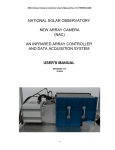
Connections
The following connections should be complete to the GNAAC and CC Thermal
Enclosures. Drawing 89-NOAO-4201-0800 is the external cabling diagram for GNIRS.
• Glycol cooling loop
• MAINS, UPS, and Cryohead power
• Data and Control LAN Ethernet connections to TE #1 (GNAAC)
• All other electrical connections at the TE rear connector panel
All GNIRS cables are labeled with a Wxxx number that matches the mating connectors
(Jxxx or Pxxx or Sxxx) at both ends. All GNIRS external cabling is wired 1 to 1 on all
functional pins.
GNIRS Service & Calibration Manual
17
Section 4
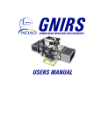
Detector Controller TEC
Components Controller TEC
Power
Glycol Coolant
Figure 4.1.1. Thermal Enclosure Cabinets (TEC)
GNIRS Service & Calibration Manual
18
Section 4
Drawing 89-NOAO-4201-0800
GNIRS Service & Calibration Manual
19
Section 4
ESD Protection
Users and handlers of GNIRS electronics or cables should be grounded to the GNIRS TE
chassis or other local ground using a standard ESD wrist strap.
Procedure
1) Connect the Glycol cooling loop through both Thermal Enclosures
and confirm coolant flow. Coolant flow is required if the TE doors are closed, but
may be off if the TE access doors are open and the system temperature monitored by
the operator.
2) Confirm the interface connectors to the instrument are connected.
The Data LAN and Control LAN Ethernet fiber-optic cables must be connected for
the PowerPC computers to successfully boot up.
3) Turn on the MAINS AC power at the power switch on the connector panel.
MAINS power is usually left on, as it powers the cooling fans and the Ethernet switch
in the GNAAC (TE #1).
4) Turn on the UPS AC power at the power switch.
This powers the majority of the components in each TE, and starts the boot-up of the
PowerPC computers.
5) Cryohead power (110VAC) from the Helium Protection system is not switched in the
TE. The He Protection power is supplied continuously to the Component Controller
Cryohead Motor Drive in crate 2 as long as the Differential Pressure Switch (DPS)
mounted on the GNIRS He manifold indicates the He pressure difference is greater
than 90 psi (measured). The DPS contacts are monitored by the ISS which switches
the He Protection AC power to the instrument in response to changes in He pressure
difference. Operation of the He Protection system is described in the Gemini Helium
Protection System document of July 2001 and on the drawing Gemini He Safety
System, Cold Heads Protection Stand Alone Box.
Power (220VAC) to the cryohead motors is switched either manually by crate 2 frontpanel switches or by software command through the XVME-240 digital I/O board.
See Section 6.5 for a description of crate 2.
6) To power down either TE, just turn off the UPS AC power at the switch on the
connector panel. For a complete power down, then turn off the MAINS AC power.
If the helium pressure remains adequate and the He Protection AC power is
connected, then there is still 110VAC and 220VAC in the Component Controller
crate 2. To ensure a completely off crate 2, disconnect the AC power cable to the He
Protection AC connector either at the ISS or at TE #2.
GNIRS Service & Calibration Manual
20
Section 4
4.1.2 Software Start-Up
The windows for the GNIRS engineering interface are EPICS dm screens, which can be
used to monitor and modify EPICS variables. Type nirsStart (script located in
{BASE}/bin/solaris) to start the top dm screen and the 4 console windows that are
connected to the four vxWorks machines associated with GNIRS. The diagnostic
windows are an interface to the CAD, CAR, APPLY records, and also show the current
status of the system. Several display buttons will display a menu when right clicking
with the mouse. Some of these menus are dynamically loaded, so if the system is
rebooted, or the menu is reloaded after the dm screen is already displayed, the right click
menu won’t be updated. This is easily fixed by exiting the affected window and redisplaying it from its parent window.
It is desirable, but not necessary, to perform this step before turning on the thermal
enclosures (4.1.1), as one can monitor the VxWorks computers as they boot up.
Descriptions of the windows and their uses can be found in the Software Maintenance
Manual, section 3.2 of the User's Manual, or sections 6.1 and 7.2 of this manual
(troubleshooting and calibration). An abbreviated description follows:
The window shown below (Fig. 4.1.2.1) is the top-level engineering window for GNIRS.
This window needs to be kept open, though it can be minimized. The other, lower-level
windows can be closed if not being used. If you do close the top-level window by
accident, type nirsStart to recover.
Figure 4.1.2.1. GNIRS top level engineering window
GNIRS Service & Calibration Manual
21
Section 4
On this window, there are four buttons, which correspond to the four major components
of the system:
• Instrument Sequencer - The instrument sequencer controls the system most like the
OCS would. It communicates with all the other systems except for the Wavefront
Sensor. This is not normally used as a direct interface to the instrument, except to
open the mechanism control window.
• Components Controller - The Components Controller monitors temperature and
pressure. It also controls the mechanisms, the detector and bench temperature, and the
cryo-motors.
• Detector Controller - The detector controller controls and monitors all functions
related to taking an image.
• Wavefront Sensor – This displays the windows which control and monitor the
mechanisms in the Wavefront sensor.
The "help" button will give a description of what all the colors on the windows
correspond to. "EXIT" kills all dm windows. The colored S/H/B indicators correspond to
“state,” “health” and “busy.”
The Components Controller window is shown in Figure 4.1.2.2. This is where all
functions related to temperature pressure and mechanism position can be controlled or
monitored.
Figure 4.1.2.2. GNIRS Components Controller window.
GNIRS Service & Calibration Manual
22
Section 4
The most useful buttons on the Components Controller window are listed below:
• Temperatures – This button starts one of three temperature monitor windows. A
right mouse click will drop down a menu for the user to pick one of the windows.
• Pressures – The pressure monitor window is displayed with this button. Only two of
the three sensors are actually in the system.
• Mechanisms – Starts a display window that will allow the user to run any of the CAD
diagnostic windows related to the ten mechanisms. There is one window per
mechanism; use the mechanism control window (see below) as an alternative.
• Park – This performs a park command on all ten mechanisms.
• Datum – This performs a datum command on all ten mechanisms.
The opto-mechanical configuration of the instrument can be controlled from a single
Mechanism Control screen (Figure 4.1.2.3). This is opened by first opening the
Instrument Sequencer screen from the top-level screen (above), and then opening the
Mechanism Control screen from the IS screen. The IS screen can then be closed.
Figure 4.1.2.3. Mechanism Control screen. This provides control for all mechanisms.
GNIRS Service & Calibration Manual
23
Section 4
The Detector Controller engineering display is displayed below (Figure 4.1.2.4).
Figure 4.1.2.4. Detector controller (GNAAC) window.
The most relevant areas on the screen are as follows:
• Image Setup – Not used with the DHS.
• Observation Setup – Shows current state of observation parameters such as: coadds,
low noise reads, digital averages, number of pictures, and integration time. In addition
the integration time can be modified here. The obsSetup CAD must be run for the
change to take effect. (“Do Obs Setup” button, or from “Observation Cntrl” in
“Setup Commands” area.) The Observation can be started, stopped or aborted here
also.
• Overall Health – Displays health of the system.
• Array Setup – Displays detector status such as the activation, uCode download state,
and bias level. (These values can be changed from the “Array Setup Cntrl” or
“Observation Cntrl” windows)
• Additional Screens – Right mouse click pulls down a menu that has a list of useful
windows.
• Setup Commands – Bring up windows that allow the user to setup all the necessary
parameters in the Detector Controller:
− Array Setup Cntrl – Download ucode, and set array voltages.
− Observation Cntrl - Set array activation, digital averages, co-adds, number of pics,
proc mode, HK process state, header detail, header timing, readout size, and
integration time.
− Data Image Cntrl – Setup simulation patterns or array readout.
GNIRS Service & Calibration Manual
24
Section 4
− The associated CAD must be started for any changes to take effect. They can be
run from their respective windows, or from the “Do Array Setup”, “Do Obs
Setup”, and “Do DR ROI Setup” buttons.
The top level OIWFS screen is shown in Figure 4.1.2.5.
Figure 4.1.2.5. Top-level OIWFS screen.
The "Wavefront Sensor CC" uses the standard CAD/CAR record structure to run the
system. This is most similar to how the A&G system will run the OIWFS.
4.1.3 Shutdown
The electronics/software shutdown procedure for GNIRS is fairly simple:
•
•
•
•
Move all mechanisms to the "park" position (see Section 6.2).
Deactivate the detector (see GNAAC manual; also see Section 4.1.2).
Disconnect cryocooler helium lines (Section 4.2.3)
Turn off all power on the thermal enclosures (mains and UPS).
Note: if access to the slit mask or an IFU position is desired, the slit slide can be moved
to the appropriate limit position (see Section 5.2.3 or 8.5.10).
The cryocooler lines should be removed prior to turning off power (see 4.2.3). Failure to
follow this sequence can lead to over-pressure in the cryocoolers as they warm up.
This shutdown procedure is required only if the instrument is being moved. If the
instrument is going to be kept cold in the same location, only carry out the first two steps,
then turn off the GNAAC UPS power (but not GNAAC MAINS).
GNIRS Service & Calibration Manual
25
Section 4
4.2 Vacuum and Cryogenic Procedures
This section covers the procedures required to evacuate (Section 4.2.2) and cool down
(Sections 4.2.3 and 4.2.4) the instrument prior to use on the telescope or in the lab, as
well as the procedures to warm it up (Section 4.2.5) and bring it to ambient pressure
(Section 4.2.6) prior to servicing.
The cool-down process can be carried out with the cryocoolers alone or with an initial
liquid nitrogen pre-cool (see Section 4.2.4 for details).
Prior to performing these procedures, read the safety section (Section 4.2.1).
4.2.1 Vacuum and Cryogenic Safety
4.2.1.1 Vacuum Safety
The dewar is normally under vacuum. Loss of vacuum or deliberate pressurization while
cold can lead to damage to optics, detectors, and possibly other components. It is
important to pressurize the dewar only when the insides are near ambient temperature,
and to do so slowly. See Section 4.2.6 for details.
It is also important to ensure that the instrument does not leak (see Section 6.4), since
such leaks will lead to an eventual loss of vacuum, and possible contamination of optics
or detectors.
If the dewar is sealed, verify that it is at ambient pressure before attempting to remove
dewar shells, covers, etc. Damage to components and even injury to people is possible if
this is not done. Note that variations in ambient pressure over time or between sea level
and the telescope are significant for an instrument this size; always verify that pressure
has been equalized immediately prior to any disassembly procedures.
4.2.1.2 Cryocooler Safety
The primary cooling for GNIRS is provided by four cryocoolers, which operate using
high-pressure, high-purity helium. Failure to follow proper procedures (Sections 4.2.3
and 5.1.2) can lead to contamination of the telescope helium supply system, and possible
damage to cold heads on GNIRS and other instruments using the system. In addition, the
high pressures involved (peak values around 300 psi) pose a potential risk during
disassembly of the instrument or disassembly of the cryocoolers; follow the specified
procedures. In particular, it is important to turn off power to the cryoheads after
disconnecting helium lines, which must be done in the correct sequence (see Section
4.2.3). Otherwise, substantial over-pressures can develop in the heads as they warm up.
4.2.1.3 Liquid Nitrogen Safety
GNIRS Service & Calibration Manual
26
Section 4
If the liquid nitrogen precool system is used for initial cooling of the instrument (Section
4.2.4), large quantities (approximately 1000 liters) of liquid nitrogen are involved. These
large volumes require not only the precautions appropriate when handling cryogenic
liquids, but also adequate ventilation to avoid asphyxiation. In addition, operation of the
pre-cool system presents a noise hazard, and hearing protection is strongly recommended.
Specifically:
• Use insulated gloves when handling the cryogen lines and connections.
• Ensure that liquid emerging from the pre-cool system is collected in a suitable storage
dewar. Avoid spilling liquid on the floor or spraying it around the room.
• Ensure that the area where the pre-cooling is being done is very well ventilated. The
pre-cool system initially generates gas volumes at rates of 30-40 cubic meters per
hour (roughly 18-25 SFCM). The ventilating system must have a minimum capacity
in excess of this range. Use of an oxygen monitor is recommended.
• Operation of the pre-cool system drives resonances in the system, and produces
intense, high-pitched noise. Hearing protection (earplugs) should be used when
working on or around the pre-cool system when it is in operation.
4.2.2 Evacuation of GNIRS
Obtaining a good vacuum within GNIRS is essential to achieving and maintaining the
operating temperature for the instrument over the course of an extended observing
session. Because of the volume and large surface area within the instrument, even a
small degradation in the vacuum can provide an additional heat load sufficient to
compromise the instrument operation. Also, the large number of closely spaced volumes
(between the passive radiation shields, within the main bench, etc.) represent “virtual
leaks” which will require a long time to achieve the required vacuum.
While the cryocooler second stages (and the molecular sieve) can cryopump residual
sources of outgassing, we strongly recommend achieving a good vacuum on the
instrument prior to cooldown, rather than using the cryopumping action of the molecular
sieve to compensate for a poor vacuum. Taking the time to achieve a good vacuum on
the instrument will act as a diagnostic for potential leaks and make the initial cooldown
(before the cold heads have achieved a sufficiently low temperature to act as efficient
cryopumps) proceed more quickly.
4.2.2.1 Philosophy
Assuming no leaks, a major component of outgassing during the pumpdown results from
the tendency of molecules, particularly H2O, to adhere to the surfaces within the
instrument. These molecules can be removed much more efficiently during the initial
evacuation from atmospheric pressure, where the viscous flow at high pressures will
dislodge them and drag them along. The recommended procedure thus involves several
cycles of pumpout and backfilling with N2 gas to flush out as much of the residual H2O
as possible. If the instrument has been opened up and exposed to atmosphere, we
GNIRS Service & Calibration Manual
27
Section 4
recommend a “bakeout” using the warmup resistors to heat the interior of the instrument
to ~ 60 C to accelerate the removal of residual molecules from the surfaces.
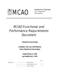
4.2.2.2 Preparation and Special Equipment
GNIRS has three valved ports (Fig. 4.2.2.2): one has a Turbomolecular pump
permanently installed; another is a port for initial (rough) evacuation; the third is used for
backfilling or venting the instrument. The Turbo pump is never removed from the
instrument and requires a mechanical “backing” pump on the output to operate. One uses
a mechanical pump to evacuate the instrument to a pressure of a few mTorr, at which
point the Turbo pump will begin to operate efficiently. The roughing port is then closed,
the mechanical pump is switched to the output of the Turbo pump, which is used to
achieve the high vacuum required. Do not evacuate the instrument from atmospheric
pressure through the Turbo pump. This is not only very inefficient but will damage
or contaminate the Turbo pump.
GNIRS Service & Calibration Manual
28
Section 4
Rough Pump
Vacuum Valve
Turbo Vacuum
Port
Dry Air
Helium Lines
Turbo Pump
Backfill Valve
Figure 4.2.2.2. Vacuum and cryo-cooler connections.
GNIRS Service & Calibration Manual
29
Section 4
A medium capacity mechanical pump is required for both the rough pumping and
backing for the Turbo pump. An oil-free Scroll pump is highly recommended. A
conventional mechanical pump can be used, but it carries the risk of oil backstreaming
into the instrument and will also generate a lot of oil “smoke” during the initial
pumpdown from atmospheric pressure because of the volume of gas being pumped.
The mechanical pump should have a “fail-safe” solenoid valve to close off the pump
from the instrument in the event of a power failure.
A source of N2 gas is required for backfilling and venting. The ~ 2m3 volume of GNIRS
is equivalent to about 70 cf, or 1/3 of a standard “220 scfm laboratory” cylinder. The use
of air for this procedure is not recommended, since even dried air contains some H2O.
The mechanical pump must have a flexible stainless vacuum line with adapters to fit the
roughing port and the backing valve port on the Turbo pump.
4.2.2.3 Evacuation and Backfilling
Three basic vacuum scenarios, in order of complexity, are:
•
•
•
“hardening” the vacuum prior to an observing session, after a period of repose at
room temperature.
Pumping down the instrument after a brief maintenance task, such as changing a
filter.
Pumping down the instrument after major maintenance requiring disassembly and/or
an extended period open to the atmosphere.
4.2.2.3.1 Pumping on an Existing Vacuum
If the instrument has been sitting around warm under vacuum for a while, one should
pump out the vacuum jacket to remove any residuals from outgassing or diffusion prior to
cooling down, as it is always a good idea to begin the cooldown with as good a vacuum
as possible.
Unless the internal pressure, as measured with the Convectorr gauge on the instrument, is
less than 10 – 20 mTorr, it is a good idea to pump the instrument to that level with the
mechanical pump prior to using the Turbo pump.
Attach the mechanical pump to the roughing port. The line should be short in length and
as large in diameter as possible for maximum pumping efficiency.
Turn on the mechanical pump and open the roughing valve. Monitor the pressure; when
it reaches about 10 mTorr, close the roughing valve, turn off the mechanical pump, and
reconnect it to the output port valve on the Turbo pump. Attaching to the small valve
will require an adapter on the vacuum line.
GNIRS Service & Calibration Manual
30
Section 4
Turn on the mechanical pump and open the output valve on the Turbo pump. Turn on the
power to the Turbo pump. It will take several minutes for the Turbo pump to spool up to
maximum speed—this is programmed into its controller.
Continue pumping until the dewar pressure has reached the level at which cooling may be
safely started. If conditions permit, continue pumping during the cooldown to evacuate
as much as possible the outgassing from the warm surfaces such as the interior of the
outer shell and the passive radiation shields.
4.2.2.3.2 Pumping Down from Ambient Pressure
If the instrument has been at ambient pressure for a short time and has not been
extensively disassembled, it should be possible to evacuate it without the need for baking
out. However, if time permits, one should remove the back shell and bake out the
molecular sieve (section 5.3) to help maintain the long-term vacuum integrity.
If the instrument has been opened for a longer period or the ambient conditions are
humid, we recommend baking out the instrument during the pumpdown (section
4.2.2.3.3).
Attach the mechanical pump to the roughing port. The line should be short in length and
as large in diameter as possible for maximum pumping efficiency.
Turn on the mechanical pump, keeping the roughing valve closed. Open the roughing
valve slightly to begin pumping. Monitor the pressure with the Convectorr gauge on the
instrument. As the pressure decreases, gradually open the roughing valve; once 10 – 20
Torr has been achieved, the valve can be fully opened. This gradual procedure prevents
overloading of the mechanical pump and is particularly important if an oil pump is used.
Continue pumping for an hour or so, noting the dewar pressure. The rate of pump-down
depends somewhat on the set-up available. Initially, the pump should be throttled back
using the vaccum valve, so that the rate is 50 T/min or less. Once the pressure reaches
100-200 T, you will probably be able to open the valve all the way. The time to reach a
pressure of ~1 T should be about half an hour (depends on pump). The pressure should be
well below 1 T after another half hour or so. Stalling at a high pressure could indicate a
leak or serious contamination (Section 6.4).
Once a pressure of ~ 100 mTorr is reached, close the roughing valve, turn off the
mechanical pump, and backfill the instrument with N2 gas through the bleed port until a
pressure near atmospheric is achieved.
Re-evacuate the instrument. We recommend at least two, and preferably three of these
cycles if the instrument is being pumped down from atmospheric pressure. On
subsequent cycles, the time to achieve a given pressure level should decrease as the
primary outgassing constituents are flushed out of the instrument.
GNIRS Service & Calibration Manual
31
Section 4
After the final backfilling, continue pumping until the pressure reaches ~ 10 mTorr.
Close the roughing valve, turn off the mechanical pump, and reconnect it to the output
port on the Turbo pump.
Turn on the mechanical pump and open the output valve on the Turbo pump. Turn on the
power to the Turbo pump. It will take several minutes for the Turbo pump to spool up to
maximum speed—this is programmed into the controller.
Continue pumping until the dewar pressure has reached the level at which cooling may be
safely started. If conditions permit, continue pumping during the cooldown to evacuate
as much as possible the outgassing from the warm surfaces such as the interior of the
outer shell and the passive radiation shields.
4.2.2.3.3 Pumping Down after Disassembly
After the instrument has been disassembled or exposed to atmospheric conditions for an
extended time, it will be necessary to bake out the instrument during the evacuation
process to get rid of the significant amounts of H2O (as well as other contaminants)
which will inevitably have been adsorbed onto the surfaces of the internal components.
Follow the procedure outlined in section 4.2.2.3.2 to pump out and backfill the
instrument with N2 gas. Carry out this procedure twice and leave the instrument
backfilled with N2.
Hookup the external power supply to the warmup resistors and enter a setpoint of 333 K
(60 C). Turn on the heaters and bake out the instrument for at least 24 hours.
NOTE: There is a reason for having the system near atmospheric pressure during this
stage of the bakeout. The N2 gas will ensure more or less isothermal heating of the entire
instrument, including the passive radiation shields, and prevent any outgassing products
from condensing on relatively thermally isolated and cooler surfaces, such as the optics.
Once the instrument has baked out for at least 24 hours, hook up the mechanical pump
and evacuate the instrument, while leaving the heaters powered on. The pumpdown will
probably be considerably slower than the norm, since the outgassing of contaminants
from the internal surfaces will continue at a good rate as the pressure falls.
If time permits, continue the heating for another 24 hours. Once the pressure drops
below 10 mTorr, one can switch over to the Turbo pump and continue the pumpout as
described in section 4.2.2.3.2.
4.2.3 Cryocooler Operation
This procedure covers the installation and removal of the He cryo lines to a cryohead, as
well as cryocooler operation. Note that the cryohead motor and gas compressor should
GNIRS Service & Calibration Manual
32
Section 4
be “ON” during these procedures. Always remove the high-pressure line before the
return line and install the return line before the high-pressure line to avoid a potentially
dangerous over-pressure situation in the cryohead.
4.2.3.1 Connecting Aeroquip Fittings
Never apply lubricants to Aeroquip fittings!
Isopropyl alcohol is the only recommended anti-seize aid; it evaporates quickly and it
doesn’t contaminate the fittings. Ensure that the fittings on both mating surfaces are
clean. Use a clean swab to wipe any dirt or particles from the threads and O-rings.
Isopropyl alcohol and a brass bristle brush may be used if necessary on the threads, then
wipe off with a clean dry wipe. Also use a flat stick to remove the male half fitting flat
seal and clean it and the groove. Do not assemble fittings with wet face seal surfaces!
Be sure the dust cap/plug is clean as well. When installing the gas lines, start the fittings
by hand and hold the line straight to avoid cross threading. Then add some isopropyl
alcohol to the coupling between the nut and body, and on the male end’s threads. Tighten
the fitting until it seats, using the appropriate wrenches. Do not over-tighten the fittings!
4.2.3.2 Instrument Start-Up
1) Connect the cryohead electronics, verify the compressor is operational and ready (i.e.,
chilled water, power, static gas pressure, etc.). Start the compressor and then the
cryohead motors. Check the return and supply lines as detailed below and, if no
contamination is detected, connect them to the instrument in that order.
2) Return side: remove the dust plug from the return hose and dust cap from the
instrument. Check all pieces for dirt and/or oil. Use a UV long wave lamp to check
each piece for compressor oil contamination. If fittings fluoresce under the UV lamp,
the system is contaminated and the instrument should not be connected. If no
contamination is detected, connect line to the instrument.
3) Pressure side: remove the dust plug from the pressure hose and dust cap from the
instrument. Check all pieces for dirt and/or oil. Use a UV long wave lamp to check
each piece for compressor oil contamination. If fittings fluoresce under the UV lamp,
the system is contaminated and the instrument should not be connected.
4.2.3.3 Instrument Shutdown
1) Pressure side: remove pressure hose from the instrument. Check all pieces for dirt
and/or oil. Use a UV long wave lamp to check each piece for compressor oil
contamination. If fittings fluoresce under the UV lamp, the system is
contaminated. Install dust plug on hose end and dust cap on instrument.
2) Return side: remove return hose from the instrument. Check all pieces for dirt
and/or oil. Use a UV long wave lamp to check each piece for compressor
instrument oil contamination. If fittings fluoresce under the UV lamp, the system
is contaminated. Install dust plug on hose end and dust cap on instrument.
GNIRS Service & Calibration Manual
33
Section 4
3) Shut down the cryohead motors and then the compressor, disconnect the cryohead
electronics. Verify the compressor static gas pressure and note this for the next
time the system is run. It is a good way to check for a system gas leak.
GNIRS Service & Calibration Manual
34
Section 4
4.2.4 GNIRS Cool-Down Procedure
This section describes procedures for cooling down the instrument, both with and without
use of the liquid nitrogen pre-cool system. The pre-cool system shortens the overall cooldown time by approximately 1 week, but requires more operator intervention, the use of
800 liters of liquid nitrogen, and appropriate safety precautions.
4.2.4.1. Cool-Down with Pre-Cool
This is an outline of the procedure for cooling down the instrument with the pre-cool
system.
4.2.4.1.1. Safety
WARNING: Asphyxiation risk. Use of the liquid nitrogen pre-cool system generates up
to 1 cubic meter of nitrogen gas per minute. Operation of the pre-cool system should
always take place in a well-ventilated area, preferably while using an oxygen monitor.
WARNING: Cryogenic liquids. Standard safety message for liquid nitrogen
WARNING: Noise hazard. Operation of the pre-cool system can generate noise at
damaging frequencies and intensities. Suitable hearing protection may be required.
WARNING? Anything associated with the cryocooler lines.
4.2.4.1.2 Theory of Operation
Cool-down with the pre-cool system functions in two stages. In the first stage, the
primary means of cooling is the pre-cool system, although the cryocoolers are also
operated to prevent their acting as a "heat leak".
The pre-cool system is a length of corrugated stainless steel tubing which runs around the
circumference of the cold structure (bench) and is attached to it at various points by
copper clamps. Liquid nitrogen flows into this tube and evaporates, cooling the bench
through the attachment points. The flow rate is regulated to evaporate all (or nearly all)
liquid that enters the system, to minimize waste of liquid nitrogen.
The pre-cool system efficiency decreases as the bench temperature approaches the
temperature of liquid nitrogen, and at this point the pre-cool system is purged and backfilled with helium gas, and further cooling is provided by the cryocoolers alone.
The purge and back-fill leave the pre-cool system with a slight over-pressure, which can
be monitored to detect slow leaks. This procedure ensures that water or other
condensables do not enter the pre-cool system and form a plug.
GNIRS Service & Calibration Manual
35
Section 4
The cryocoolers cool the bench through a connection between their first stages and the
bench, which consists of 8 heavy copper straps connected to the bench at different points
on its center section. Additional straps are connected to the active shield.
There is also a connection from the second stages of heads 1 and 2, which cools the
detector mount and the getter (molecular sieve) below 35K.
Once the instrument reaches the desired temperature, the bench temperature control can
be turned on (section 7.3).
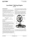
4.2.4.1.3 Preparation
Cool-down should not be initiated until the instrument vacuum has reached a pressure
below 10-3 T. If the instrument is to be used for an extended period of time, a pressure 12x10-4T is recommended.
The instrument control electronics should be turned on. Verify that the dewar
temperatures and pressure are being correctly monitored.
Figure 4.2.4.1.3. LN2 Pre-cool Manifold.
GNIRS Service & Calibration Manual
36
Section 4
Connect the high-pressure helium lines to the instrument connector panel (Section 4.2.3).
If the instrument has been disassembled, verify that all connections from the panel to the
cryocoolers have been made. Also verify that power connections have been made
between the instrument controller enclosure and the cryocoolers.
Connect a flexible fill line from a storage dewar (160 liters or greater capacity
recommended) to the fill port on the pre-cool system. Remove the pressure gauge/pop-off
fitting from the vent port on the pre-cool system. Attach a flexible line to the vent port
and allow it to vent into a suitable receptacle (empty nitrogen dewar).
The pre-cool procedure will produce substantial condensation on the fill and vent lines,
so they should be insulated with foam pipe insulation, or wrapped with towels or
something similar to protect electronics cabinets and cables from water. Note that the fill
lines from the pre-cool manifold to the dewar are already insulated.
If you insulate the fill line, it will increase efficiency slightly. Also, you can increase the
time between storage dewar changes by connecting two dewars with a “T” connection.
This is especially useful for running the pre-cool overnight.
Dry nitrogen/dry air should be connected to the dewar window (connect at instrument
connector panel, check connections between panel and window cover). The window
cover should be closed. Set the gas flow rate to 5lpm using the control on the connector
panel.
4.2.4.1.4 Cryocooler Start
Turn on the cryocoolers using the manual controls inside the instrument controller
thermal enclosure. Make sure that all four heads are operating.
Operate for approximately 20 minutes. The output lines on all four heads should feel
distinctly warm to the touch, and should be at roughly similar temperatures. If this is not
the case, proceed to Section 6.3 on cryocooler troubleshooting.
After 20 minutes, the temperature sensors on the cryocoolers should indicate a
temperature drop of 20K or more.
4.2.4.1.5 Pre-Cool Start
Open the valve to the storage dewar partially. Flow through the fill line should be
audible, but do not open the valve all the way. Wait a minute or two. If there is no liquid
emerging from the vent line, open the valve somewhat more. If there is liquid emerging,
proceed to the next step.
Assuming that there is liquid emerging from the vent line (it may only be dripping), close
the valve on the storage dewar slightly. Allow a couple of minutes, and if liquid is still
GNIRS Service & Calibration Manual
37
Section 4
emerging, close the valve some more. The point of this procedure is to set the flow rate
just below the point where liquid nitrogen makes it through the system without
evaporating.
At this optimal flow rate, the pre-cool system will usually produce a loud and annoying
whistle. If you are going to be working in the vicinity, use hearing protection.
Check on the pre-cool system after half an hour or so to confirm that the flow rate
remains optimal. If there is gas flow but no whistling, flow rate is probably too low. If
there is liquid dripping, the flow rate is too high. It is difficult to exactly optimize the
flow rate; a very slow drip will not waste too much nitrogen, and will ensure maximum
cooling.
At the optimal flow rate, liquid consumption is approximately 35 l/hour. Check on the
level in the storage dewar to monitor consumption, since this number is approximate.
Also check on the bench temperatures as the pre-cool operates. The rate of cooling
should be ~13 K/hour initially, decreasing gradually to 10K/hour as the bench
temperature drops below 200K. The rate as the bench approaches 100K will decrease to
~5/K hour.
When the storage dewar is empty, it should be disconnected and replaced (or refilled).
Adjust the flow rate for the new dewar in the same way.
4.2.4.1.6 Pre-Cool Stop
Once the bench temperature approaches 100K, pre-cool efficiency will decrease and it
will be necessary to cut back the flow rate. This point will not be reached until 15+ hours
have passed.
The initial flow rate is expected to be in the vicinity of 30 l/hour, which will empty a
small storage dewar in ~5 hours or a large one in ~8 hours. As the cooling efficiency
decreases, the optimum flow rate will also decrease.
The pre-cool system functions well down to bench temperatures approaching 80K. It
should therefore be allowed to operate until one of the following occurs:
• A bench temperature point reaches 77K
• Bench temperature points are all below 85K
At this point the liquid nitrogen valve should be closed.
4.2.4.1.7 Pre-Cool Purge and Back-Fill
The pre-cool input should now be connected to a source of dry nitrogen (do not use dry
air for this purpose). A reasonable source is the "vent" valve on the liquid nitrogen
storage dewar.
GNIRS Service & Calibration Manual
38
Section 4
It will almost certainly be necessary to use a heat gun to melt ice in order to change the
connections.
Open the vent valve all the way. Blow nitrogen through the pre-cool system until all
liquid has been blown out; run for roughly another minute.
Now close the nitrogen valve and connect a helium bottle to the helium gas fitting. Lab
grade helium (not high purity) is adequate for this purpose. Purge the pre-cool system
with helium gas for 30-60 seconds, then close the valve on the output (vent) of the precool system. Allow the pre-cool system to pressurize to approximately 5 psi or until the
pop-off valve activates.
The pressure in the line will initially increase as the bench temperature equalizes and
warms the pre-cool line slightly; it will then decrease as the bench cools further. The
pressure drop from 80 to 60K is almost 5 psi.
Monitor the pre-cool pressure as the instrument cooling progresses, and top off with
additional He if the pressure drops below 2 psi. Rapid drops in pressure, or decreases
once the instrument temperature has stabilized, are indicative of a leak.
After this step, all cooling will be provided by the cryocoolers. The bench should reach a
temperature <65K after about 3 days of cooldown.
4.2.4.1.8 Final Cooling with Cryocoolers
The cryocoolers are already functioning, so no steps are needed beyond monitoring the
temperature. Cooling from 80 to 60 K requires ~1 day. The bench temperature control
can be turned on at any time once the bench is at or below 80 K (see Section 7.3)
4.2.4.2. Cool-Down without Pre-Cool
This section describes the procedures for cooling down the instrument without using the
pre-cool system, using the cryocoolers only.
4.2.4.2.1 Safety
WARNING? Anything associated with the cryocooler lines.
4.2.4.2.2 Theory of Operation
The cryocoolers cool the bench through a connection between their first stages and the
bench, which consists of 8 heavy copper straps connected to the bench at different points
on its center section. Additional straps are connected to the active shield.
GNIRS Service & Calibration Manual
39
Section 4
There is also a connection from the second stages of heads 1 and 2, which cools the
detector mount and the getter (molecular sieve) below 35K.
Once the instrument reaches the desired temperature, the bench temperature control can
be turned on (Section 6.5.4).
4.2.4.2.3 Preparation
Cool-down should not be initiated until the instrument vacuum has reached a pressure
below 10-3T. If the instrument is to be used for an extended period of time, a pressure less
than 1-2x10⁻⁴T is recommended.
The instrument control electronics should be turned on. Verify that the dewar
temperatures and pressure are being correctly monitored.
Connect the high pressure helium lines to the instrument connector panel. If the
instrument has been disassembled, verify that all connections from the panel to the
cryocoolers have been made. Also verify that power connections have been made
between the instrument controller enclosure and the cryocoolers.
Connect a helium bottle to the helium fitting on the pre-cool system manifold. Verify that
the pressure reading on the pre-cool system is 5 psi or greater. If it is lower, the system
should be purged and back-filled with helium gas, as follows:
• Open the vent valve on the pre-cool system.
• Purge the system for 30-60 seconds
• Close the vent valve and allow the system to pressurize to 5 psi or until the pop-off
valve operates.
Dry nitrogen/dry air should be connected to the dewar window (connect at instrument
connector panel, check connections between the panel and window cover). The window
cover should be closed. Set the gas flow rate to ~2 liters/minute using the control on the
connector panel. Set the pressure gauge to ~3 psi.
4.2.4.2.4 Cryocooler Start
Turn on the cryocoolers using the manual controls inside the instrument controller
thermal enclosure. Make sure that all four heads are operating.
Operate for approximately 20 minutes. The output lines on all four heads should feel
distinctly warm to the touch, and should be at roughly similar temperatures. If this is not
the case, proceed to Section 6.3 on cooler troubleshooting.
After 20 minutes, the temperature sensors on the cryocoolers should indicate a
temperature drop of 20K or more.
GNIRS Service & Calibration Manual
40
Section 4
4.2.4.2.5 Cryocooler Cooling
The cryocoolers will operate unattended. The cooling rate is initially ~30K/day
(estimated) decreasing to ~20K/day.
The pressure in the pre-cool system will decrease as the system temperature decreases,
and if unattended will drop below atmospheric pressure. This should be avoided since
there is then a potential for condensibles to enter the pre-cool line. Therefore, the pressure
should be checked roughly once a day and the pre-cool system should be topped off with
helium gas if the pressure has dropped below 3 psi (see section 4.2.4.2.3 above). It is not
necessary to purge the pre-cool system unless pressure has dropped to zero (below
atmosphere).
Total cool-down time is estimated as 10 days. (The cooldown mode has not been tested.)
The bench temperature control can be turned on once both the Offner and collimator
temperature sensors reach 80K (see section 6.5.4).
4.2.5 GNIRS Warm-Up Procedure
This section describes the procedure for warming up the instrument using the stand-alone
heater box.
4.2.5.1. Warm-Up Procedure
4.2.5.1.1 Safety
There are no particular safety concerns provided the warm-up is done according to the
instructions in this section.
4.2.5.1.2 Theory of Operation
The warm-up box warms up the instrument using 48 resistors distributed over the internal
cold structure. When the heater circuits are on, these resistors dissipate approximately
1000W. Some additional heating occurs from radiation through the shields, and
conduction down the cold straps from the warm cryocoolers.
In order to minimize risk to the optics from thermal shock, the heater box monitors the
rate of change of the bench temperature at the control diode, and limits heating to
10K/hour or less.
This results in a warm up time of slightly over 1 day.
It is recommended that the dewar be connected to a vacuum pump during warm up, as
this helps remove contaminants as they outgas from the coldheads and the molecular
sieve.
GNIRS Service & Calibration Manual
41
Section 4
4.2.5.1.3 Operation
The cryocoolers should be turned off, and may be disconnected; see Section 4.2.3.3.
Connect a roughing pump to the turbo-pump and turn it on. Once line pressure has
stabilized, plug in the turbo-pump (it will turn on automatically). Although this step is
strongly recommended, it is possible to carry out the warm up without it. The pump can
be connected prior to turning off the cryocoolers. The instrument controller electronics
need to be on to read pressure, unless alternative connections are made to the gauges.
The dewar electronics can be left on, though this is not required. If the electronics are
turned off, there is no way to log temperature or monitor pressure for the warm-up.
The stand-alone heater box should be connected to the heater connector (J719 on the
starboard [right] forward side of the bulkhead). Before connecting the heater box cable,
verify that the connector on the bulkhead is free of condensation. If there is condensation,
use a heat gun to dry the connector. Do not overheat the connector as this can damage the
O-ring seal or the connector itself.
Turn on the warmup controller, which is described further in Section 6.5.5. Select a set
point using the switches on the front panel (4 possible temperatures using combinations
of switches 1 and 2). A set point somewhat above room temperature is recommended in
order to maximize removal of contaminants. However, if the intent is to immediately
open the instrument, then the set point should be set close to room temperature to
minimize the risk of thermal shock to the optics.
If all circuits are operational, all 6 lights on the face of the box should illuminate. Note
that the temperature control is an "on-off" control, so if the warm up rate needs to be
limited, or if the set point is approached, the circuits will turn off intermittently. The duty
cycle during initial stages of the warm-up may be as low as 25% "on." If the warm-up
box is operating normally, the circuit should start applying power at a 50% duty cycle
immediately at turn on. The duty cycle will initially be about 5 to 10 seconds. If the
power remains on continuously (more than 1 minute), turn the box off immediately and
then check the programming of the Omega controller [Described in Section 7.3].
WARNING: Do not attempt to re-program the heater box unless you are prepared to
monitor the instrument temperatures on the next use, and you understand what you are
doing, and why. The heaters are capable of warming the instrument up at a rate that poses
a risk to the optics.
Once the internal temperature reaches the set point that was selected, the box will stop
heating the instrument. If the set point is higher than ambient, the box will turn power on
as needed to maintain the higher temperature. If the next step is to open the instrument,
see Section 8 of the service manual.
GNIRS Service & Calibration Manual
42
Section 4
If the next step is to put GNIRS into storage (waiting for next use), continue pumping the
dewar until a pressure of 10-3 Torr is reached. Then turn off and disconnect the heater
box, then turn off and close the backing valve on the turbo-pump and remove the backing
pump (Section 4.2.2.2.)
4.2.6. Backfilling the Instrument Prior to Maintenance
If the instrument is to be warmed up for maintenance, follow the warmup procedure
outlined in section 4.2.5 or, if time permits, simply allow the instrument to return
naturally to ambient temperature.
Prior to opening up the instrument, backfill to atmospheric pressure with N2 gas. If the
instrument will be opened for only a short time (for replacing a filter or the window),
backfilling with N2 will minimize the adsorption of H2O onto the internal surfaces and
greatly facilitate the subsequent pump down. Even if extensive maintenance or
disassembly is intended, the N2 backfill will be of some help in limiting H2O adsorption
on the surfaces.
GNIRS Service & Calibration Manual
43
Section 4