1
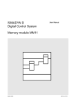
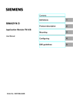
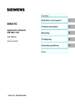
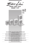
SIMADYN D
Digital Control System
User Manual
Interface module SE47.1
Edition 05.95
DK-Nr. 283341
User Manual, Interface module SE47.1
Edition
Edition status
1
Interface module SE47.1
04.91
2
Interface module SE47.1
05.95
Copying of this document and giving it to others and the use or
communication of the contents thereof is forbidden without express
authority. Offenders are liable to the payment of damages. All rights
are reserved in the event of the grant of a patent or the registration of
a utility model or design.
We have checked the contents of this Manual to ensure that they
coincide with the described hardware and software. However,
deviations cannot be completely ruled-out, so we cannot guarantee
complete conformance. However, the information in this document is
regularly checked and the necessary corrections included in
subsequent editions. We are thankful for any recommendations or
suggestions.
Contents
Contents
Warning information................................ ................................ ................................ ...................... 1
1. Description................................ ................................ ................................ ................................ 3
2. Design................................ ................................ ................................ ................................ ....... 3
3. Application Notes ................................ ................................ ................................ ...................... 3
4. Technical Specification ................................ ................................ ................................ ............. 4
5. Plug Connector Allocation................................ ................................ ................................ ......... 5
5.1. Allocation of the 25 pin SUB D socket strip X1................................ ........................... 5
5.2. Allocation of the 9 pin SUB D socket strips X2,X3................................ .................... 5
6. Terms/Abbreviations ................................ ................................ ................................ ................. 5
7. Literature................................ ................................ ................................ ................................ ... 5
8. Appendices ................................ ................................ ................................ ............................... 6
9. ECB instructions................................ ................................ ................................ ........................ 7
Siemens AG Dk-Nr. 283341
SIMADYN D Hardware User Manual
Edition 05.95
Warning information
Edition 05.95
Siemens AG Dk-Nr. 283341
SIMADYN D Hardware User Manual
Warning information
NOTE!
The information in this Manual does not purport to cover all details or variations in equipment, nor to provide
for every possible contingency to be met in connection with installation, operation or maintenance.
Should further information be desired or should particular problems arise which are not covered sufficiently for
the purchaser’s purposes, please contact your local Siemens office.
Further, the contents of this Manual shall not become a part of or modify any prior or existing agreement,
committment or relationship. The sales contract contains the entire obligation of Siemens. The warranty
contained in the contract between the parties is the sole warranty of Siemens. Any statements contained
herein do not create new warranties nor modify the existing warranty.
Warning information
WARNING!
Electrical equipment has components which are at dangerous voltage levels.
If these instructions are not strictly adhered to, severe bodily injury and material
damage can result.
Only appropriately qualified personnel may work on this equipment or in its
vicinity.
This personnel must be completely knowledgeable about all the warnings and
service measures according to this User Manual.
The successful and safe operation of this equipment is dependent on proper
handling, installation, operation and maintenance.
Siemens AG Dk-Nr. 283341
SIMADYN D Hardware User Manual
Edition 05.95
1
Warning information
Definitions
*
QUALIFIED PERSONNEL
*
DANGER
*
WARNING
*
CAUTION
*
NOTE
For the purpose of this User Manual and product labels, a „Qualified person“ is someone who is familiar with the
installation, mounting, start-up and operation of the equipment and the hazards involved. He or she must have
the following qualifications:
1. Trained and authorized to energize, de-energize, clear, ground and tag circuits and equipment in accordance
with established safety procedures.
2. Trained in the proper care and use of protective equipment in accordance with established safety
procedures.
3. Trained in rendering first aid.
For the purpose of this User Manual and product labels, „Danger“ indicates death, severe personal injury and/or
substantial property damage will result if proper precautions are not taken.
For the purpose of this User Manual and product labels, „Warning“ indicates death, severe personal injury or
property damage can result if proper precautions are not taken.
For the purpose of this User Manual and product labels, „Caution“ indicates that minor personal injury or
material damage can result if proper precautions are not taken.
For the purpose of this User Manual, „Note“ indicates information about the product or the respective part of the
User Manual which is essential to highlight.
CAUTION!
This board contains components which can be destroyed by electrostatic
discharge. Prior to touching any electronics board, your body must be electrically
discharged. This can be simply done by touching a conductive, grounded object
immediately beforehand (e.g. bare metal cabinet components, socket protective
conductor contact).
WARNING!
Hazardous voltages are present in this electrical equipment during operation.
Non-observance of the safety instructions can result in severe personal injury or
property damage.
It is especially important that the warning information in all of the relevant
Operating Instructions are strictly observed.
2
Edition 05.95
Siemens AG Dk-Nr. 283341
SIMADYN D Hardware User Manual
Description
1. Description
The bus interface module (BIM) SE 47.1 order no. : 6DD1681-0EH1 is an interface module designed
for the communication of DUST 4 in the SIMADYN D control system.
BIM FUNCTION
1. A Manchester Encoder/Decoder MED implements :
a) the synchronization, i.e. generating the data transfer clock
b) the conversion of the SCC data format, NRZ code, in manchester code and back.
2. The RTS signal, software controlled, switches the bus accessing.
3. The interface IC's, designed to RS485 specification, convert the MED input/output signals to
thesignal format of the transmission path.
4. A counter, triggered by an encoder clock, monitors the telegram length.
Each BIM is connected to a DUST 4 partner via a plug connector cable, in which the data, the control
signals and 5V power supply are transmitted. The transfer path consists of bus cables and plug
connectors with which the BIM's are inter-connected. The first and last BIM in the system are
terminated with a plug containing a terminating resistance.
2. Design
* Casing (support element), snap-on rail mounting
* Metal cover as fault protection
* Screen connection
- M3 threaded bolts
* SUB-D - socket strips
- 25 pin, for the plug connection to the processor board.
- 2x9 pin, for the plug connection to the serial bus.
* Indicators , LED's :
- red ( receive )
- green ( transmit )
* HF-Transformers for voltage isolation between SIMADYN D and the transfer path
3. Application Notes
To be used:
for the partner:
Interface SS3:RS485
order no.6DD1688-1AC0
as connection from BIM to the partner: cable SC27:RS485
order no.6DD1684-0CH0
for the serial bus : 1. Parts sets SUB-D 9pin SM5:pins
order no.6DD1680-0AF0
2. Terminating plug
SM6
order no.6DD1680-0AG0
3. cable Data , limit values
| Example *)
External diameter
8mm, maximum (because of casing)
6,6mm
Screen
total screen
total screen
1 twisted pair
2 twisted pairs
Conductors
Conductor diameter 0,8mm, maximum (solder connection) 0,32mm [AWG 28]
Wave impedance
100.....150 Ohm
120 Ohm
Siemens AG Dk-Nr. 283341
SIMADYN D Hardware User Manual
Edition 05.95
3
Technical Specification
*)low loss cable for EIA RS485 applications, BELDEN ELECTRONICS, cable no. 8132
4. Technical Specification
INSULATION GROUP
AMBIENT TEMPERATURE
STORAGE TEMPERATURE
HUMIDITY CLASS
PROTECTION TYPE
MECHANICAL STRESS
acc. VDE 0110 / 1.89 for contamination grade 2
0 to 55 deg. C
-40 to 70 deg. C
F acc. DIN 40040
IP00 acc. DIN 40050
acc. SN 29010 class 12
PACKAGING SYSTEM
DIMENSIONS
WEIGHT
snap-on rail mounting
135 x 77 x 58.5 (mm)
165 gr.
ELECTRICAL DATA
SUPPLY
- VOLTAGE DC (Uv) :
- CURRENT
INPUTS
- VOLTAGE
- SENSITIVITY
- HYSTERESIS
- RESISTANCE
OUTPUTS
- VOLTAGE
with load
- RESISTANCE
- SHORT CIRCUIT CURRENT
min.
typ.
max.
4,75 V
250 mA
5V
5,75 V
-7
± 200 mV
50 mV
12 K
± 1,5 V
+ 12 V
without load ± Uv
54 R
500mA
DATA RATE
*)
TOTAL LENGTH OF THE BUS CABLE *)
NUMBER OF PARTNERS
1 MBit/s
200 m
32
*)/1/ Guide lines for the selection of cables are available in section A2.
/2/ shows in section 9.2 typical values for the cable lengths dependent upon the transmission speed
(example : telephone cable).
4
Edition 05.95
Siemens AG Dk-Nr. 283341
SIMADYN D Hardware User Manual
Plug Connector Allocation
5. Plug Connector Allocation
5.1. Allocation of the 25 pin SUB D socket strip X1
Pin
1
2
3
4
5
6
7
8
9
10
11
12
13
Designation
NC
not connected
*RTS (+)
*TRxC(+) Transmit/Receive Clock
NC
TxD (+) Transmit Data
*RTxC(+) Receive/Transmit Clock
*DCD (+) Data Carrier Detect
RxD (+) Receive Data
M
Ground
NC
NC
NC
NC
Pin
14
15
16
17
18
19
20
21
22
23
24
25
Designation
*RTS (-)
*TRxC(-) Transmit/Receive Clock
NC
TxD (-) Transmit Data
M
Ground
*RTxC(-) Receive/Transmit Clock
*DCD (-) Data Carrier Detect
RxD (-) Receive Data
P5
Supply 5 V
P5
Supply 5 V
NC
NC
5.2. Allocation of the 9 pin SUB D socket strips X2,X3
Pin
1
2
3
4
5
Designation
Signal A
(Pin 1 & 2 connected)
Signal A
5 V (via resistance 1k2)
NC
Screen
Pin
6
7
8
9
Designation
Signal B
(Pin 6 & 7 connected)
Signal B
Ground (via resistance 1k2)
Screen
6. Terms/Abbreviations
BIM
Bus interface module
DUST
Data transmission control
MED
Manchester Encoder and Decoder
NRZ
Non Return to Zero
SCC
Serial Communication Controller
Partner on the communication participating processor board
7. Literature
/1/
EIA RS485 Version: April 83
Electrical Characteristics of Generators and Receivers
of use in Balanced Digital Multipoint Systems
/2/
DIN 66 259 Teil 3: Maerz 1983
Elektrische Eigenschaften der Schnittstellenleitungen
Doppelstrom, symmetrisch, bis 10 Mbit/s
Siemens AG Dk-Nr. 283341
SIMADYN D Hardware User Manual
Edition 05.95
5
Appendices
8. Appendices
Application notes
Appendix 1
Processor module :
Partner 1
Partner 2
Partner n
Partner z
SE 47. 1
SE 47. 1
SE 47. 1
SS3:
RS 485
Cable
SC 27
Interface module
SE 47. 1
Plug terminator
Cable 2,5 mm 2
Voltege equalizing cable
SE 47. 1
X2
A
B
SE 47. 1
Screened buscable
twisted pair
X3
1
1
6
6
2
2
7
M
3
NC
4
8
NC
NC
NC
Connection when
2 twisted pair available
4
NC
M
8
NC
NC
NC
NC
5
9
P5
NC
3
NC
B
7
NC
P5
A
5
9
Connections for
voltage equalizing
Overview block diagram
3GE 465 681 9047.10 SU
Dimension Drawing & Connector Allocation table
3GE 465 681 9047.10 MB
6
Edition 05.95
Siemens AG Dk-Nr. 283341
SIMADYN D Hardware User Manual
ECB instructions
9. ECB instructions
Components which can be destroyed by electrostatic discharge (ECB)
Generally, electronic boards should only be touched when absolutely necessary.
The human body must be electrically discharged before touching an electronic board. This can be
simply done by touching a conductive, grounded object directly beforehand (e.g. bare metal cubicle
components, socket outlet protective conductor contact.
Boards must not come into contact with highly-insulating materials - e.g. plastic foils, insulated
desktops, articles of clothing manufactured from man-made fibers.
Boards must only be placed on conductive surfaces.
When soldering, the soldering iron tip must be grounded.
Boards and components should only be stored and transported in conductive packaging (e.g.
metalized plastic boxes, metal containers).
If the packing material is not conductive, the boards must be wrapped with a conductive packing
material, e.g. conductive foam rubber or household aluminum foil.
The necessary ECB protective measures are clearly shown in the following diagram.
a = Conductive floor surface
b = ECB table
c = ECB shoes
Seated
Siemens AG Dk-Nr. 283341
SIMADYN D Hardware User Manual
d = ECB overall
e = ECB chain
f = Cubicle ground connection
Standing
Edition 05.95
Standing/sitting
7
ECB instructions
8
Edition 05.95
Siemens AG Dk-Nr. 283341
SIMADYN D Hardware User Manual
ECB instructions
Drives and Standard Products
Motors and Drives Systems Group
Postfach 3269, D-91050 Erlangen
Siemens AG Dk-Nr. 283341
SIMADYN D Hardware User Manual
System-Based
Technology
Edition 05.95
9