1
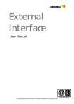
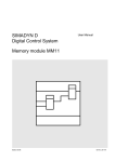
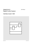
SIMADYN D
Digital Control System
User Manual
Prozessor module PS16
Edition 05.95
DK-Nr. 223142
Warning information
User Manual, Prozessor module PS16
Edition
Edition status
1
Prozessor module PS16
03.91
2
Prozessor module PS16
05.95
Copying of this document and giving it to others and the use or
communication of the contents thereof is forbidden without express
authority. Offenders are liable to the payment of damages. All rights
are reserved in the event of the grant of a patent or the registration of
a utility model or design.
We have checked the contents of this Manual to ensure that they
coincide with the described hardware and software. However,
deviations cannot be completely ruled-out, so we cannot guarantee
complete conformance. However, the information in this document is
regularly checked and the necessary corrections included in
subsequent editions. We are thankful for any recommendations or
suggestions.
Edition 05.95
Siemens AG Dk-Nr. 223142
SIMADYN D Hardware User Manual
Contents
Contents
Warning information................................ ................................ ................................ ...................... 1
1. Order Designation:................................ ................................ ................................ .................... 3
2. Function Description ................................ ................................ ................................ ................. 3
3. Board Design ................................ ................................ ................................ ............................ 4
4. Application notes................................ ................................ ................................ ....................... 5
5. Technical Specification ................................ ................................ ................................ ............. 8
6. Pin Allocation of the PS16................................ ................................ ................................ ......... 9
6.1. Pin Allocation of the serial Interface X01................................ ................................ .... 9
6.2. Timer inputs and outputs X5 pin allocation................................ ................................ . 10
6.3. Pin allocation of the binary inputs X6 ................................ ................................ ......... 10
6.4. Pin allocation of the frequency inputs X7................................ ................................ .... 11
7. STRUC L-Mask of the PS16 board in the master program................................ ......................... 12
8. Appendices ................................ ................................ ................................ ............................... 14
8.1. Block diagram................................ ................................ ................................ ............ 14
8.2. Scale drawing with table of the plug connector................................ ........................... 14
8.3. Allocation diagram ................................ ................................ ................................ ..... 14
9. Miscellaneous ................................ ................................ ................................ ........................... 14
9.1. Designations/Abbreviations................................ ................................ ........................ 14
10. ECB instructions................................ ................................ ................................ ...................... 15
Siemens AG Dk-Nr. 223142
SIMADYN D Hardware User Manual
Edition 05.95
Warning information
Edition 05.95
Siemens AG Dk-Nr. 223142
SIMADYN D Hardware User Manual
Warning information
NOTE!
The information in this Manual does not purport to cover all details or variations in equipment, nor to provide
for every possible contingency to be met in connection with installation, operation or maintenance.
Should further information be desired or should particular problems arise which are not covered sufficiently for
the purchaser’s purposes, please contact your local Siemens office.
Further, the contents of this Manual shall not become a part of or modify any prior or existing agreement,
committment or relationship. The sales contract contains the entire obligation of Siemens. The warranty
contained in the contract between the parties is the sole warranty of Siemens. Any statements contained
herein do not create new warranties nor modify the existing warranty.
Warning information
WARNING!
Electrical equipment has components which are at dangerous voltage levels.
If these instructions are not strictly adhered to, severe bodily injury and material
damage can result.
Only appropriately qualified personnel may work on this equipment or in its
vicinity.
This personnel must be completely knowledgeable about all the warnings and
service measures according to this User Manual.
The successful and safe operation of this equipment is dependent on proper
handling, installation, operation and maintenance.
Siemens AG Dk-Nr. 223142
SIMADYN D Hardware User Manual
Edition 05.95
1
Warning information
Definitions
*
QUALIFIED PERSONNEL
*
DANGER
*
WARNING
*
CAUTION
*
NOTE
For the purpose of this User Manual and product labels, a „Qualified person“ is someone who is familiar with the
installation, mounting, start-up and operation of the equipment and the hazards involved. He or she must have
the following qualifications:
1. Trained and authorized to energize, de-energize, clear, ground and tag circuits and equipment in accordance
with established safety procedures.
2. Trained in the proper care and use of protective equipment in accordance with established safety
procedures.
3. Trained in rendering first aid.
For the purpose of this User Manual and product labels, „Danger“ indicates death, severe personal injury and/or
substantial property damage will result if proper precautions are not taken.
For the purpose of this User Manual and product labels, „Warning“ indicates death, severe personal injury or
property damage can result if proper precautions are not taken.
For the purpose of this User Manual and product labels, „Caution“ indicates that minor personal injury or
material damage can result if proper precautions are not taken.
For the purpose of this User Manual, „Note“ indicates information about the product or the respective part of the
User Manual which is essential to highlight.
CAUTION!
This board contains components which can be destroyed by electrostatic
discharge. Prior to touching any electronics board, your body must be electrically
discharged. This can be simply done by touching a conductive, grounded object
immediately beforehand (e.g. bare metal cabinet components, socket protective
conductor contact).
WARNING!
Hazardous voltages are present in this electrical equipment during operation.
Non-observance of the safety instructions can result in severe personal injury or
property damage.
It is especially important that the warning information in all of the relevant
Operating Instructions are strictly observed.
2
Edition 05.95
Siemens AG Dk-Nr. 223142
SIMADYN D Hardware User Manual
Order Designation:
1. Order Designation:
6DD 1602-0AE0
Processor board PS16 (SIMOVERT S)
2. Function Description
The processor board PS16 is designed to process technological control, numerical and regulating
functions in the SIMADYN D system. The board is especially suitable for the software processing of
actual values in converters. The board is designed around the 16 microprocessor 80C186 with the
corresponding peripherals.
Plug-in memory modules are used to contain the user programs as well as the system firmware
(operating system, monitor program and function module code). These modules (MS...) are plugged
into the board connector X50. The user programs run on the processor under the SIMADYN D real
time operating system. This guarantees interrupt controlled fixed cycle times, dependent upon the
configuration, of ≥ 1ms .
The PS16 board contains 8 binary inputs (plug connector X6) that may also be configured as interrupt
controlled inputs. The processor interrupts the current cyclic processing, when an edge occurs at one
of these inputs and immediately begins processing the interrupt controlled function packet (process
interrupt job, PIJ). The inputs are connected with the various SIMADYN D interface modules via a 10
conductor ribbon cable.
The board is designed with 8 Frequency/digital converter inputs for the acquisition of actual values
(plug connector X7). Frequency modulated signals can be read via these inputs and converted to
digital values for further processing. The analog actual values are channeled via the SE21 interface
module, whereby 2, 4, 8 of the input channels may be selected and read in parallel. In addition, the
board contains 4 binary outputs on the X7 plug connector.
The inputs and outputs of the processor internal timers T0 and T1 can be externally accessed via the
X5 plug connector. The serial interface (plug connector X01) is designed for diagnostics using the
SIMADYN D host terminals PG 675 or PG 685.
The 7 segment display H1 on the board front panel indicates the configured processor ID code in
normal operation. The display flashes with an error code when an fault occurs on the board.
The error messages are described in the processor board user manual /1/.
The display shows a "-" during system start up.
The HEX monitor is activated if the S1 key is pressed and an error code is being displayed.
A board reset (start up) can be forced using the test jacks X10 and X11 . The test jacks should be
bridged with either a switch or a shorting jumper. The board is designed with a 50 pin (X4) and a 10
pin (X9) plug connector for hardware diagnostics using a logic analyzer or for the connection of a
passive recorder.
Three "watchdogs" are available for each processor module to monitor the hardware and software
functionality.
The hardware monitor checks:
- whether the processor generates new addresses within a certain time
- whether addresses are accessed that are not used
Siemens AG Dk-Nr. 223142
SIMADYN D Hardware User Manual
Edition 05.95
3
Board Design
The software monitor checks:
- whether the processor is still running a cyclic program
- whether the interrupt controller of the serial interfaces, timers and inputs are operating without
error
A non-maskable interrupt (NMI) is generated when the monitor detects an error. The processor tries to
eliminate the cause of the error and resume normal cyclic operation. If the cause of error lies with the
processor itself, then the board switches itself inactive, the red dot on the 7 segment display is
activated and bus line "system error" activated.
3. Board Design
* SIMADYN D local bus connection
* CPU 80C186 16 Mhz
* RAM 64 k Byte; battery back-up from the power supply (PS)
* Plug recess for the program memory sub-modules MS...
* 8 Frequency inputs without voltage isolation with frequency/digital converter
* 8 Binary inputs without voltage isolation; interrupt capability
* 4 Binary outputs
* Processor timer inputs and outputs
* Serial interface; optional V24 (RS232) or 20 mA (TTY)
* Real time clock; resolution 10 ms, battery back-up from the PS
* 7 segment display for the configured processor number and error display
* Hardware and software monitor through 'watchdogs'
* Test connector for the connection of logic analyzers or recorders
4
Edition 05.95
Siemens AG Dk-Nr. 223142
SIMADYN D Hardware User Manual
Application notes
4. Application notes
The processor board can be implemented in both the wide racks (SR1/5) and the narrow racks
(SR2/4). It requires two rack slots.
The board must be fixed to the rack by screws, even in the commissioning phase, to ensure perfect
operation.
The front panel must be shorted to the rack by a short conductor when the board is placed on an
adapter board.
The board must never either be inserted or removed from the rack when under power.
A thick film circuit (hybrid module) must be installed on the X51 location when the serial interface X01
is to be used. The following hybrid modules are currently available:
SS1
SS2
:
:
20 mA (TTY)
V.24 (RS 232)
Warning: Correct installation important (See screen print)
Connection possibilities for the PS16 processor module:
a) Binary inputs
PS16
X6
Flachkabel
10 polig
INTERFACE
MODUL
EXTERNEANSCHLÜßE
Siemens AG Dk-Nr. 223142
SIMADYN D Hardware User Manual
Edition 05.95
5
Application notes
b) Frequency/Digital inputs and Binary outputs
PS16
X7
Flachkabel
40 polig
INTERFACE
MODUL
X3
SE21.1
EXTERNEANSCHLÜßE
c) Processor timer inputs and outputs
Currently no connection implemented
Supplementary components for the PS16 :
a) Serial interface
* Hybrid interface
SS1 (20 mA)
6DD 1688-1AA0
* Hybrid interface
SS2 (V24)
6DD 1688-1AB0
* Cable PS16-PG 685
SC32 20 mA, 10 m
6DD 1684-0DC0
* Set of parts 25 pin
Cannon plug
SM3.1
6DD 1680-0AD0
* 10-pin
2.0 m SC7
6DD 1684-0AH0
* 40-pin ---> 4x10-pin
2.0 m SC13
6DD 1684-0BD0
* 40-pin
2.0 m SC18
6DD 1684-0BJ0
b) Ribbon cable
6
Edition 05.95
Siemens AG Dk-Nr. 223142
SIMADYN D Hardware User Manual
Application notes
c) Interface Module
* SE3.1
16 Binary inputs and 16 Binary outputs
no voltage isolation
6DD 1681-0AD1
* SE4.1
8 Binary inputs or 8 Binary outputs
no voltage isolation
6DD 1681-0AE1
* SE5.3
8 Binary inputs 220 V
voltage isolation
6DD 1681-0AF3
* SE21.2
PS11/16 Interface for frequency inputs
6DD 1681-0CB2
* SE41.1
8 Binary inputs 48 V
voltage isolation
6DD 1681-0EB1
Siemens AG Dk-Nr. 223142
SIMADYN D Hardware User Manual
Edition 05.95
7
Technical Specification
5. Technical Specification
INSULATION GROUP
AMBIENT TEMPERATURE
STORAGE TEMPERATURE
HUMIDITY CLASS
ALTITUDE RATING
MECHANICAL STRESS
PACKAGING SYSTEM
DIMENSIONS
BOARD WIDTH
WEIGHT
CURRENT CONSUMPTION
A to VDE 0110 paragraph 13, group 2 at 24, 15 and 5 VDC
0 to 55 deg. C
-40 to +70 deg. C
F to DIN 40040
S to DIN 40040
Installation in fixed vibration resistant devices
ES 902 C
233.4 x 220 mm
2 2/3 SEP = 2 Slot = 40.28 mm
0.6 Kg
+ 5 VDC
+15 VDC
-15 VDC
VCRAM
BINARY INPUTS
NUMBER
INPUT VOLTAGE
INPUT VOLTAGE
FOR 0 SIGNAL
FOR 1 SIGNAL
INPUT CURRENT
AT 1 SIGNAL
DELAY TIME
2.8 A
50 mA
50 mA
0.5 mA
8 not voltage isolated
+24 V Rated value
-1 V to +6 V; or Binary inputs open
+13 V to +33 V
Typ. 3 mA
< 200 us
BINARY OUTPUTS
NUMBER
4 not voltage isolated
SUPPLY VOLTAGE
supply externally
-RATED VALUE
24 VDC
-HARMONICS
3.6 VDC
-PERM. RANGE
+ 20 to + 30 V incl. harmonics
-TRANSIENTS
+ 35 V smaller than 0,5 sec.
OUTPUT CURRENT AT 1 SIGNAL
-RATED VALUE
50 mA
-PERM. RANGE
0.2 mA to 50 mA
SHORT CIRCUIT PROTECT.
electronic
INDUCTIVE LIMIT
TRIPPING VOLTAGE
to Vcc + 1V
MAXIMUM LOADING
80% at 50 Deg. C. all outputs 50 mA
RESIDUAL CURRENT
20 uA at 0 Signal
SIGNAL LEVEL
-AT 0 SIGNAL
max. 3V
-AT 1 SIGNAL
min. supply - 2,5V
Switching delay
15 uS
FREQUENCY INPUTS
NUMBER
MINIMUM
INPUT FREQUENCY
MAXIMUM
INPUT FREQUENCY
INPUT VOLTAGE
FOR 0 SIGNAL
FOR 1 SIGNAL
INPUT CURRENT
AT 1 SIGNAL
DELAY TIME
8
8 not voltage isolated
30 kHz
90 kHz
24 V Rated valu&e
-1 V at +6 V
+13 V at +33 V
Typ. 2 mA
< 6.6 uS
Edition 05.95
Siemens AG Dk-Nr. 223142
SIMADYN D Hardware User Manual
Pin Allocation of the PS16
6. Pin Allocation of the PS16
6.1. Pin Allocation of the serial Interface X01
PIN
1
2
3
4
5
6
7
8
9
10
11
12
13
14
15
16
17
18
19
20
21
22
23
24
25
V 24
FRAME GROUND
TRANSMIT DATA OUT
RECEIVE DATA IN
REQUEST TO SEND OUT
CLEAR TO SEND
DATA SET READY IN
GROUND
DATA CARRIER DETECT IN
GROUND
--+15 V
------RECEIVE/TRANSMIT CLOCK
--RECEIVE/TRANSMIT CLOCK
GROUND
--DATA TERMINAL READY OUT
--+5 V
+5 V
TRANSMIT RECEIVE CLOCK
-15 V
Siemens AG Dk-Nr. 223142
SIMADYN D Hardware User Manual
T*D
R*D
*RTS
*CTS
*DCD
*RT*C
*TR*C
20 MA (TTY)
FRAME GROUND
----------GROUND
--GROUND
CURRENT LOOP + TRANSMIT
+15 V
20 MA SOURCE 1
CURRENT LOOP + RECEIVE
CURRENT LOOP - RECEIVE
--20 MA SOURCE 2
--GROUND
CURRENT LOOP - TRANSMIT
--20 MA DRAIN 2
+5 V
+5 V
20 MA DRAIN 1
-15 V
Edition 05.95
+T*D
+R*D
-R*D
-T*D
9
Pin Allocation of the PS16
6.2. Timer inputs and outputs X5 pin allocation
Pin
1
2
3
4
5
6
7
8
9
10
Designation
Timer 0 Output
Timer 1 Output
|
--|
--Timer 0 Input
Timer 1 Input
|
--|
--P external
M external
6.3. Pin allocation of the binary inputs X6
Pin
1
2
3
4
5
6
7
8
9
10
10
Designation
Input 1
Input 2
Input 3
Input 4
Input 5
Input 6
Input 7
Input 8
P external
M external
Plug section
X6 A
X6 A
X6 A
X6 A
X6 A
X6 A
X6 A
X6 A
X6 A
X6 A
Edition 05.95
Siemens AG Dk-Nr. 223142
SIMADYN D Hardware User Manual
Pin Allocation of the PS16
6.4. Pin allocation of the frequency inputs X7
Pin
1
2
3
4
5
6
7
8
9
10
11
12
13
14
15
16
17
18
19
20
21
22
23
24
25
26
27
28
29
30
31
32
33
34
35
36
37
38
39
40
Designation
shield
shield
Input 1
shield
shield
Input 2
shield
BAG 1
P external
M external
shield
shield
Input 3
shield
shield
Input 4
shield
BAG 2
P external
M external
shield
shield
Input 5
shield
shield
Input 6
shield
BAG 3
P external
M external
shield
shield
Input 7
shield
shield
Input 8
shield
BAG 4
P external
M external
Siemens AG Dk-Nr. 223142
SIMADYN D Hardware User Manual
Plug section
X7 A
X7 B
X7 C
X7 C
X7 D
X7 I
X7 E
X7 F
X7 I
X7 G
X7 H
X7 I
Edition 05.95
11
STRUC L-Mask of the PS16 board in the master program
7. STRUC L-Mask of the PS16 board in the master program
: PS16
PIJ 1N = 0
SFJ 1N = 0
PRX 1N = 0
PJ1 1N = ?
PJ2 1N = 0
PJ3 1N = 0
PJ4 1N = 0
PJ5 1N = 0
PJ6 1N = 0
PJ7 1N = 0
PJ8 1N = 0
PTX 1N = 0
ILS IK = 0
T0 TG = ?
T1 TS = ?
T2 TS = ?
T3 TS = ?
T4 TS = ?
T5 TS = ?
TY TX = T?
SSM 2C = 0
ISE 1C = N
CCT 8R = 0
CCR 8R = 0
COP 8R = 0
CMS 8N = 0
CTS 8N = 0
MS 2M = 0
X6A 8K <
X7A 1K <
X7B 1K <
X7C 1K <
X7D 1K <
X7E 1K <
X7F 1K <
X7G 1K <
X7H 1K <
X7I 4K >
"processor module SIMOVERT S, L-bus"
"alarm processing FP"
"system error FP"
"special communication FP receive"
"1. permanent processing FP"
"special communication FP transmit"
"L-Bus-Interrupt transmit"
"basic sampling time"
"1. s.t.*T0,produced LB-conn."
"2. s.t.
''
"
"3. s.t.
''
"
"4. s.t.
''
"
"5. s.t.
''
"
"sampling time of system FP"
"Length SAVE-area, (n*1+2) kByte"
"Ignore failed message (RDYINT) (Y/N) ?"
"Transmitter communication names.Tx"
"Receiver communication names.Tx"
"Service communication names.Tx"
"Message system names"
"Comm. transport system names"
"Message systems"
"Binary inp.,intrpt. contr."
"F/D converter 1"
"F/D converter 2"
"F/D converter 3"
"F/D converter 4"
"F/D converter 5"
"F/D converter 6"
"F/D converter 7"
"F/D converter 8"
"Binary outputs"
The PS16 requires 1 sub-module
* 1 x Program memory
12
Edition 05.95
Siemens AG Dk-Nr. 223142
SIMADYN D Hardware User Manual
STRUC L-Mask of the PS16 board in the master program
The connectors X6 and X7 can be accessed, for the frequency and binary inputs, by the following
function modules:
Plug section Function module
X6A ----
- BII8
- BID8
- SBI
X7A X7B -
-- - IST
- FDC
- IWE
X7C X7D -
-- - IST
- FDC
- IWE
X7E X7F -
-- - IST
- FDC
- IWE
X7G X7H -
-- - IST
- FDC
- IWE
Binary input (8 Binary values)
Binary input (8 Binary values, normal mode)
Input status byte
F/D converter (1-8)
X7I -------- /
Siemens AG Dk-Nr. 223142
SIMADYN D Hardware User Manual
Edition 05.95
13
Appendices
8. Appendices
8.1. Block diagram
Block diagram
3GE.465 602.9004.00 SU
8.2. Scale drawing with table of the plug connector
Scale drawing with view of the front panel and the table
of the used plug connectors:
3GE.465 602.9004.00 MB
8.3. Allocation diagram
Allocation diagram
3GE.465 602.9004.00 AO
9. Miscellaneous
9.1. Designations/Abbreviations
14
Edition 05.95
Siemens AG Dk-Nr. 223142
SIMADYN D Hardware User Manual
ECB instructions
10. ECB instructions
Components which can be destroyed by electrostatic discharge (ECB)
Generally, electronic boards should only be touched when absolutely necessary.
The human body must be electrically discharged before touching an electronic board. This can be
simply done by touching a conductive, grounded object directly beforehand (e.g. bare metal cubicle
components, socket outlet protective conductor contact.
Boards must not come into contact with highly-insulating materials - e.g. plastic foils, insulated
desktops, articles of clothing manufactured from man-made fibers.
Boards must only be placed on conductive surfaces.
When soldering, the soldering iron tip must be grounded.
Boards and components should only be stored and transported in conductive packaging (e.g.
metalized plastic boxes, metal containers).
If the packing material is not conductive, the boards must be wrapped with a conductive packing
material, e.g. conductive foam rubber or household aluminum foil.
The necessary ECB protective measures are clearly shown in the following diagram.
a = Conductive floor surface
b = ECB table
c = ECB shoes
Seated
Siemens AG Dk-Nr. 223142
SIMADYN D Hardware User Manual
d = ECB overall
e = ECB chain
f = Cubicle ground connection
Standing
Edition 05.95
Standing/sitting
15
ECB instructions
16
Edition 05.95
Siemens AG Dk-Nr. 223142
SIMADYN D Hardware User Manual
ECB instructions
Drives and Standard Products
Motors and Drives Systems Group
Postfach 3269, D-91050 Erlangen
Siemens AG Dk-Nr. 223142
SIMADYN D Hardware User Manual
System-Based
Technology
Edition 05.95
17