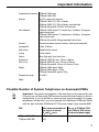
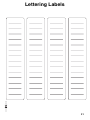
1
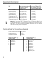
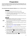
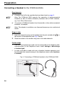
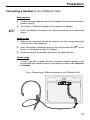
Commissioning Instructions
System Telephones and Answering Machine
COMfortel쏐 2500
COMfortel쏐 1500
COMfortel쏐 Voicemail
Symbols Used in the Manual
This symbol warns of potential personal injury caused from electrical voltage.
☞
This symbol warns of potential property damage.
This symbol warns of possible user errors and circumstances that might lead to
functional restrictions or malfunctions.
☞
This symbol indicates supplemental information and tips.
1
This symbol indicates a visible result of an action that was just carried out,
for example, a display message or a blinking LED.
2
This symbol indicates an audible result of an action that was just carried out,
for example, the playback of an announcement.
L This symbol identifies useful operating information for new users.
Definition of Terms/Glossary
Firmware
Operating software on the telephone or PBX that is stored in the device itself.
The device cannot function without firmware.
Firmware update
The process of updating the firmware to resolve problems and integrate new
features. When this is done, the device establishes a connection to a server in
order to download the current firmware (the device settings remain intact).
Except for the charges for the required telephone connection, the update is free
of charge.
Information about the Accompanying Instructions
Additional instructions: The operation and configuration of the telephones
and the answering machine are thoroughly described in the User Manual. The
User Manual is located on the Auerswald Mega Disk included in the package
under Manuals. In addition, it is important to take note of the information about
guarantee service, environment, CE compliance and conformity in the enclosed
flyer “Conditions of guarantee, Information service”.
The latest information: After functional extensions have been installed during
a firmware update, you will receive current instructions on the support pages on
the Auerswald website (Internet address: www.auerswald.de).
Copyright: Passing on or duplicating the contents of this manual or parts of it
is only allowed with our express written permission. Offenders will be subject to
claims for damages. All rights reserved. 쏘 Auerswald GmbH & Co. KG, 38162
Cremlingen, 2008
Table of Contents
Table of Contents
Symbols Used in the Manual ................................................................................................ 2
Definition of Terms/Glossary................................................................................................. 2
Information about the Accompanying Instructions ................................................................ 2
Important Information......................................................................................................... 4
Safety Information ................................................................................................................. 4
Proper Use ............................................................................................................................ 5
Technical Data ...................................................................................................................... 6
Possible Number of System Telephones on Auerswald PBXs ............................................. 7
Technical Data for Connecting a Headset ............................................................................ 8
Preparation .......................................................................................................................... 9
Connecting the Key Extension Modules (only for COMfortel 2500)...................................... 9
Connecting the Receiver..................................................................................................... 11
Connecting a Headset (to the COMfortel 2500).................................................................. 12
Connecting a Headset (to the COMfortel 1500).................................................................. 13
Situating the Telephone ...................................................................................................... 14
Commissioning ................................................................................................................. 15
Putting the Telephone into Operation ................................................................................. 15
Commissioning the Answering Machine (only for COMfortel 2500).................................... 17
Creating an Announcement for the Answering Machine (only for COMfortel 2500) ........... 19
Connecting the Telephone to a Computer (only for COMfortel 2500)................................. 20
Installing the COMfortel Set Configuration Software........................................................... 21
Configuring the Telephone and Answering Machine via the Computer .............................. 22
Appendix............................................................................................................................ 24
Querying the firmware version/serial number ..................................................................... 24
Starting a Firmware Update ................................................................................................ 24
Distributing Firmware .......................................................................................................... 25
Releasing the COMfortel Voicemail Function (only for COMfortel 2500)............................ 26
Inserting the Lettering Label................................................................................................ 30
Cleaning the Telephone ...................................................................................................... 30
Lettering Labels ................................................................................................................ 31
Index................................................................................................................................... 35
3
Important Information
Important Information
This section includes necessary information for operating the devices safely. Before you put
the telephone into operation, it is absolutely necessary for you to read the safety information
described here and to make yourself familiar with the intended use of the device as well as
the technical information.
Safety Information
Warning: Improper use or replacement of the wall-mounted power supply
can cause a life-threatening electric shock or may damage or destroy the
device:
씮 Therefore, when using the COMfortel Xtension30 key extension modules (not included in the package), only use the wall-mounted COMfortel XT-PS power supply type No. 809.
씮 Make sure the plug is inserted securely into the wall mains outlet. Loose
plugs or damaged outlets are a fire hazard.
씮 Do not pull on the cable of the wall-mounted power supply. Carefully pull
the wall-mounted power supply out of the socket if you want to switch
off device power.
씮 If the wall-mounted power supply becomes damaged: Cut off the mains
power in the house first before pulling the plug out of the wall-mounted
power supply.
씮 Be sure to follow the applicable regulations when handling 230 V system voltage and devices attached to the mains.
Warning: Touching a defective connection cable may cause a lifethreatening electric shock. Also any damage to the casing or to the device
itself may be hazardous to life and limb.
씮 Only insert the plugs into the appropriate wall outlets.
씮 Replace damaged connection lines immediately.
씮 Repairs should be carried out immediately and only by an expert. Contact your authorized dealer or the manufacturer directly.
씮 Use original components only.
씮 Do not touch the plug contacts with sharp, metallic or moist objects.
씮 The device should not be carried by the cables.
씮 Use the cable channels available on the back of the telephone to reduce
strain when carrying the device.
Warning: Liquids entering the casing can cause life-threatening electric
shocks or damage/destroy the device.
씮 Select the installation location carefully and when cleaning the casing to
prevent liquids from entering the casing.
4
Important Information
씮 The telephone must not be used in wet environments (for example, bath
rooms).
☞
Important: Auerswald products are not designed, manufactured or
intended for use or resale in environments requiring fail-safe performance,
such as in the operation of life-support systems and/or nuclear facilities.
Use or sale of our products for these purposes is only allowed with prior
written permission by Auerswald for each individual incident.
☞
Proper Use
Important: Improper use may cause, e.g. functional restrictions or interference, the destruction of the device or, in a worst case scenario, personal
injury.
씮 If you are still not sure of the intended use of the product after reading
the following section, please contact your vendor.
The COMfortel 1500 and COMfortel 2500 are system telephones.
System telephones are intended exclusively for connecting to an internal S0 or
UP0 port of the following PBX units from Auerswald: COMpact 2204 USB,
COMpact 2206 USB, COMpact 4406 DSL, COMpact 4410 USB, COMpact
5010 VoIP, COMpact 5020 VoIP, COMmander Basic (19"), COMmander
Basic.2 (19") and COMmander Business (19").
☞
Note: Connecting to a PBX from another manufacturer or to the external S0
connection of a network provider is not intended.
System telephones are not cordless and are intended for use in closed, dry
rooms.
System telephones are different from “normal telephones” connected to PBXs
in that they are especially easy to use. Most of the functions available on the
PBXs such as internal and external calls, Do-not-Disturb and call forwarding can
be operated over the display or by simply pressing previously programmed buttons. In addition, the PBX system telephones support offered functions for telephone switch boards (for example, the Waiting Field) and various telephone
number lists (for example, the telephone book or call list).
System telephones can be configured using not only the menu displayed on the
device but also using the computer software included in the package. The computer required for this is either connected directly to the telephone USB port
(only for the COMfortel 2500) or to a computer port on the PBX.
5
Important Information
System telephones make it possible to make calls not only using the connected
receiver but also via the integrated loudspeakers (handsfree operation).
Another option is to connect a headset (not included in the package).
The COMfortel 2500 supports the operation of cable-connected headsets as
well as wireless headsets (headsets with a DHSG interface, e.g. from GN or
Plantronics). The COMfortel 1500 supports the operation of cable-connected
headsets. The connection to the COMfortel 1500 is made to the receiver jack
instead of to the receiver.
With up to three COMfortel Xtension30 key extension modules (not included in
the package) the COMfortel 2500 can be extended by freely programmable
function keys. The modules can be connected on the left or right of the telephone at your choice. A fully extended telephone has 105 freely programmable
function keys available.
The COMfortel Voicemail software function (not included in the package; feebased activation at the Upgrade Centre) and a commercially-available SD card
(not included in the package) let you add an answering machine to the COMfortel 2500.
☞
☞
Note: In the COMfortel 2500 AB (special COMfortel 2500 model), the COMfortel Voicemail function and the SD card required for it are included in the
factory settings.
Note: Accessory and service components are available at your authorized
dealer or in the Internet shop distriCOM at http://www.districom-online.de.
(Shipping only available in Germany.)
Technical Data
6
Operating voltage
Voltage via internal S0 port or UP0 port through the PBX;
COMfortel 2500 with COMfortel Xtension30: Voltage via wallmounted power supply is necessary; 230 V 쓒; 앧10%; 50 Hz
Wall-mounted power
supply
COMfortel XT-PS; type number 809
Power consumption
Max. 2 W; COMfortel 2500 fully extended: max. 8 W (wall-mounted
power supply is necessary)
System connection
Internal S0 port or UP0 port of one of the following PBX:
COMmander Business (19"), COMmander Basic.2 (19"),
COMmander Basic (19"), COMpact 5020 VoIP, COMpact 5010 VoIP,
COMpact 4410 USB, COMpact 4406 DSL, COMpact 2206 USB or
COMpact 2204 USB
Important Information
Computer/data interface COMfortel 1500: none
COMfortel 2500: USB
Displays
18 LEDs, some multi-coloured
COMfortel 1500: LCD, 128 x 32 pixels
COMfortel 2500: LCD, 128 x 64 pixels, white backlight
COMfortel Xtension30: 30 LEDs, multi-coloured
User elements
COMfortel 1500: keypad, 11 function keys, 6 softkeys, 15 programmable function keys
COMfortel 2500: keypad, 11 function keys, 8 softkeys, 15 programmable function keys
COMfortel Xtension30: 30 programmable function keys
Handset
Electret microphone, dynamic receiver, hearing aid compatible
Loudspeaker
8 Ohm, Ø 66 mm
Hook switch
Magnetic switch contact
Casing
Plastic material
Colours
White (light grey), dark blue, black
Dimensions
(W x D x H)
COMfortel 1500: 261 mm x 216 mm x 89 mm
COMfortel 2500: 261 mm x 216 mm x 109 mm
COMfortel Xtension30: 146 mm x 216 mm x 55 mm
Weight
COMfortel 1500: approx. 980 g
COMfortel 2500: approx. 1120 g
COMfortel Xtension30: approx. 410 g
Temperature range
0° to 40°C
Safety
CE
Possible Number of System Telephones on Auerswald PBXs
☞
Important: The power consumption of the terminals on the internal S0 and
UP0 ports on an Auerswald PBX may not exceed the listed values in the following table. If you would like to connect more than the number of system
telephones stated here, you must operate the additional COMfortel 2500s
with the wall-mounted COMfortel XT-PS power supply (type number 809).
PBX
Max. power consumption of Max. no. of COMfortel 1500
the sum of all internal
and COMfortel 2500 without
S0 and UP0 ports
wall-mounted power supply
COMpact 2204 USB
2.5 W
1
COMpact 2206 USB
4W
2
7
Important Information
Max. power consumption of Max. no. of COMfortel 1500
and COMfortel 2500 without
the sum of all internal
wall-mounted power supply
S0 and UP0 ports
PBX
COMpact 4406 DSL
12 W (4 W per port)
6 (2 per port)
COMpact 4410 USB
12 W (4 W per port)
6 (2 per port)
COMpact 5010 VoIP
8 W (4 W per port)
4 (2 per port)
COMpact 5020 VoIP
24 W (4 W per port)
12 (2 per port)
COMmander Basic (19")
32 W (4 W per port)
16 (2 per port)
COMmander Basic.2 (19")
60 W (4 W per port)
30 (2 per port)
COMmander Business (19")
160 W (4 W per port)
80 (2 per port)
☞
Important: If using the PBX COMmander Basic, COMmander Basic.2 and
COMmander Business, the max. power consumption also includes the analogue ports. For each connected analogue subscriber, you must deduct
1 W from the max. power consumption.
Technical Data for Connecting a Headset
8
Current microphone consumption
Max. 0.5 mA
Microphone sensitivity
45 DB
Loudspeaker impedance
150 Ohm
Receiver jack pinout
(COMfortel 1500)
Headset jack pinout
(COMfortel 2500)
1
Microphone +
1
DHSG BUS_IN
2
Loudspeaker +
2
DHSG GND
3
Loudspeaker -
3
Microphone -
4
Microphone -
4
Loudspeaker -
5
Loudspeaker +
6
Microphone +
7
DHSG + 3.3 V
8
DHSG BUS_OUT
Preparation
Preparation
This section describes the preparations required before commissioning the device. This
includes connecting the key extension modules (not included in the package) as well as the
receiver and/or a headset (not included in the package). Furthermore, this includes installing
the telephone in a suitable location.
Connecting the Key Extension Modules (only for COMfortel 2500)
Requirements
✔
Up to three COMfortel Xtension30 key extension modules
✔
A wall-mounted COMfortel XT-PS power supply (type number 809)
✔
The installation material included with the extension modules (interlock
connector, screws and connection cable).
✔
Telephone switched off (disconnected from the PBX and from the 230 V
mains power.
Steps to take
1. Place the telephone and the key extension modules to be connected on the
table in the position in which they are to be assembled.
☞
Note: The key extension modules (up to three modules are possible) can
be attached to the right or left side of the telephone. A connection to both
sides is not possible.
2. Turn the telephone and the key extension modules upside down so that the
bottom is in front of you.
3. Use the special connector included in the package to put the components
together as shown in Fig. 1 on page 10 at the bottom.
☞
Note: In Fig. 1 on page 10, the modules have been attached to the left side
next to the receiver.
4. Attach the interlock connector with the help of the four screws enclosed.
5. Insert the smaller plug (RJ-10) on the module connection cable enclosed
into the jack marked with
on the bottom of the telephone.
6. Insert the larger plug (RJ-11) on the module connection cable enclosed into
the jack marked with
on the bottom of the first key extension module.
7. Additional modules: Insert the smaller plug (RJ-10) on the module connection cable enclosed into the jack marked with
viously connected key extension module.
on the bottom of the pre-
9
Preparation
8. Insert the larger plug (RJ-11) on the module connection cable enclosed into
the jack marked with
tension module.
on the bottom of the previously connected key ex-
9. Remove the bridge plug from the jack marked with
on the bottom of the
telephone.
10. Insert the Western Modular plug for the wall-mounted COMfortel XT-PS
power supply into the jack marked with
on the bottom of the telephone.
Wait to connect to the 230 V power supply until the device is to be operated
for the first time.
Warning: Using the wrong wall-mounted power supply may cause a lifethreatening electric shock or may damage or destroy the device:
씮 Use only the wall-mounted COMfortel XT-PS power supply (type
number 809).
Fig. 1: Connecting and Mounting the COMfortel Xtension30
Key Extension
10
Preparation
11. Put the cables into the existing cable channels and empty spaces in such a
manner that the cables will not fall and cause the telephone to wobble.
Connecting the Receiver
Steps to take
1. Insert the plug, as is shown below in Fig. 2, on the longer straight end of the
spiral cord into the jack marked with
on the bottom of the telephone.
2. Guide the cable to the outside using the corresponding cable channel (see
Fig. 2).
3. Insert the other end of the spiral cord into the jack on the receiver.
Fig. 2: Receiver Connection
11
Preparation
Connecting a Headset (to the COMfortel 2500)
Requirements
✔
☞
Note: The COMfortel 2500 supports the operation of cable-connected
headsets as well as wireless headsets (headsets with a DHSG interface,
e.g. from GN or Plantronics).
✔
☞
A headset that fulfils the specified technical data listed on page 8.
To connect a COMfortel headset from Auerswald or other cable-connected
headsets: an adapter
Note: The adapter is available as an Auerswald accessory at an authorized
dealer.
Steps to take
1. Insert the connection plug on the headset into the jack marked with
on
the bottom of the telephone (see Fig. 3 below).
2. Guide the cable to the outside using one of the cable channels.
Further steps
쑱 After this, the headset type used must be configured in the telephone after
commissioning (in the telephone menu under settings def.settings
headset type).
쑱 In order to be able to make calls over a headset, headset operation must
be activated after commissioning (in the telephone menu under functions
headset).
Fig. 3: Connecting a COMfortel headset to the COMfortel 2500
12
Preparation
Connecting a Headset (to the COMfortel 1500)
Requirements
☞
✔
A cable-connected headset that fulfils the specified technical specifications
listed on page 8.
✔
To connect a COMfortel headset from Auerswald: an adapter
Note: The adapter is available as an Auerswald accessory at an authorized
dealer.
Steps to take
1. Remove the connection plug on the receiver from the corresponding jack
on the bottom of the telephone.
2. Insert the headset connection plug into the jack marked with
on the
bottom of the telephone (see Fig. 4 below).
3. Guide the cable to the outside using one of the cable channels.
Further steps
쑱 In order to be able to make calls over a headset, headset operation must
be activated after commissioning (in the telephone menu under functions
headset).
Fig. 4: Connecting a COMfortel Headset to the COMfortel 1500
13
Preparation
Situating the Telephone
Requirements
✔
☞
The existing connections in the immediate vicinity of the installation location:
for the operation with COMfortel Xtension30 key extension modules: a
230 V power socket
an ISDN socket outlet connected to the PBX
Note: The system telephone can be operated not only on an internal S0 port
but also on a UP0 port on the PBX. Only one telephone can be connected
per UP0 port. Also see the PBX manual.
Warning: Liquids entering the casing can cause life-threatening electric
shocks or damage/destroy the device.
씮 Only operate the system telephone in closed, dry rooms.
Attention: Mechanical stress and electro-magnetic fields can result in the
damage or destruction of the device or interfere in its function.
씮 Avoid mechanical stress (for example, vibrations) and the proximity of
equipment that radiates electro-magnetic fields (for example, amateur
radio sets, mobile phones, DECT systems, WLAN routers, etc. ).
씮 Protect the system telephone from direct sunshine, condensation, dirt,
dust, caustic liquids and steam.
씮 Note the values for ambient temperature and humidity indicated in the
technical specifications.
Steps to take
1. Place the telephone on a clean, flat surface.
Attention: Some plastics and paints used on furniture may react chemically with the device feet. This chemical reaction might cause damage to
the surface of your furniture.
씮 Place the system telephone on a non-slip pad.
14
Commissioning
Commissioning
This section describes how to put the telephone and answering machine on your
COMfortel 2500 into operation by inserting a commercial SD card (not included in the package). Once you have finished putting the equipment into operation, you will be able to use
the telephone immediately. You can easily customize your telephone and the answering
machine using the computer configuration described at the end of this section.
Putting the Telephone into Operation
Requirements
✔
PBX switched on (connected to the 230 V power supply)
✔
An internal telephone number for the system telephone on the internal S0
or UP0 port of the PBX entered into the configuration (COMset)
☞
☞
☞
Note: Only connect one ISDN device for each internal subscriber telephone
number to your PBX.
✔
For the operation with COMfortel Xtension30 key extension modules: the
wall-mounted COMfortel XT-PS power supply (type number 809)
✔
For the operation with no COMfortel Xtension30 key extension modules:
The bridge plug is inserted into the jack
.
✔
PBX with at least the following firmware version:
쐽
2.0H or higher (COMpact 5010 VoIP, COMpact 5020 VoIP, COMmander
Basic.2 and COMmander Business)
쐽
2.1F or higher (COMpact 2204 USB, COMpact 2206 USB, COMpact
4406 DSL, COMpact 4410 USB and COMmander Basic).
Note: If you have devices with older firmware versions, please update the
corresponding devices (see the PBX manual).
Important: If a system telephone that has been previously attached to
another (older) PBX is connected to a COMpact 5010/5020 VoIP or a COMmander Basic.2/Business (or vice versa), the existing configuration is permanently deleted during commissioning.
씮 Therefore, save the data you will need before starting the commissioning procedure. During commissioning, your are asked whether a PBX
change should be done. Press the
softkey (key next to the display).
Steps to take
1. Insert the plug of the ISDN cable included in the package, as shown below
in Fig. 5, into the jack marked with
on the bottom of the telephone.
15
Commissioning
2. Guide the cable to the outside through one of the cable channels (see
Fig. 5).
Fig. 5: Connecting to the PBX
3. Turn the telephone around again.
4. Insert the other ISDN cable into an ISDN wall jack connected to the PBX.
5. If required, insert the wall-mounted COMfortel XT-PS power supply (type
number 809) into a freely-accessible 230 V mains socket.
1
For a short moment, the Auerswald logo and then the language
menu are shown on the display.
6. Press the
softkey next to the required language.
L You can use the
softkeys (keys next to the display) in any list to
browse to the required option.
1
The MSN entry menu is shown on the display.
7. Use the keypad to enter the internal telephone number previously configured in the PBX.
L Use the softkey (key next to the display) to delete the numbers one at a
time from the right.
8. Press the
1
☞
softkey to complete the entry.
The date and time as well as the name of the internal subscriber
are shown on the display. The telephone is now ready for use.
Note: If the date and time are not yet configured in the PBX, only the name
and version of the telephone are shown on the display.
Further steps
쑱 Configure the telephone according to your individual needs. You can perform the configuration not only using the menu on the display (see the User
16
Commissioning
Manual on the CD included in the package) but also using the computer
software included in the package (recommended; see page 22).
쑱 If necessary, carry out a firmware update in order to extend the telephone
with the newly available functions (see page 24). Information about new
features and updates is available on the support pages at the Auerswald
website (Internet address: www.auerswald.de).
Commissioning the Answering Machine (only for COMfortel 2500)
Requirements
☞
✔
Telephone with firmware version 3.6B or higher.
✔
Standard SD card with the following features:
SD memory card specification 1.01 with a capacity of up to 2 GB.
According to the SD memory card specification 2.00, larger SDHC cards
are not supported.
FAT16 formatting. An SD card formatted as FAT32 can be reformatted
in the telephone after commissioning. To do this, press the menu key
and enter “#206” (also see the manual on the enclosed CD).
Note: In the COMfortel 2500 AB (special COMfortel 2500 model), the
COMfortel Voicemail function and the SD card with various professional
announcements required for it are included in the factory settings. The
answering machine can be used immediately after commissioning the telephone. The step for inserting the SD card as described here is omitted.
Steps to take
1. Open the plastic cover to the left on the back of the system telephone (see
Fig. 6 on page 18).
2. Insert the SD card with the contacts directed upwardly first into the slot (see
Fig. 6 on page 18).
3. Close the plastic cover again.
1
When
is shown at the bottom right of the display, this indicates that the SD card has been initialized and the required directory structure has been created.
1
As soon as the
symbol is shown instead of
, the answering machine is ready to start. Inbound calls are accepted (at first
without an announcement).
17
Commissioning
Fig. 6: Insert the SD Card
SD card
☞
☞
☞
SD card slot on the back
of the telephone
Note: If the initialization is not successful after inserting the SD card (
still visible with short interruptions), the SD card is not supported.
is
Note: You can switch off the standby feature (call acceptance) by pressing
the
softkey (key next to the display) and reactivate it by pressing the
softkey. The symbol always reflects the current status.
Note: After inserting the SD card, the COMfortel Voicemail function is activated for 30 days until the paid release is downloaded from the Upgrade
Centre.
Further steps
쑱 Create one or more separate announcements (see page 19).
쑱 Configure the answering machine according to your individual needs. You
can perform the configuration not only using the menu on the display (see
the User Manual on the CD included in the package) but also using the
computer software included in the package (recommended; see page 22).
쑱 When configuring the answering machine (see page 22), load the standard
announcements for accepting calls, remote playback and message forwarding onto the SD card.
쑱 If you would like to continue using the answering machine after the 30-day
testing phase, activate the COMfortel Voicemail function via the Upgrade
Centre (see page 26). The activation on the COMfortel 2500 AB is omitted
(special COMfortel 2500 model).
☞
18
Note: If you would like to remove the SD card, you can unlock it by pressing
lightly on the slot.
Commissioning
Creating an Announcement for the Answering Machine (only for
COMfortel 2500)
Steps to take
1. Press the menu key (to the left, below the display).
1
The menu for operating and configuring the telephone opens.
2. Press the
softkeys (keys next to the display) one after the other next to
the options answer.machine, settings, edit announcem. and new announcement.
L You can use the
softkeys (keys next to the display) in any list to
browse to the required option.
1
The display will show the menu for entering the name of the announcement.
3. Enter a name for the announcement using the keypad.
L Use the softkey (key next to the display) to delete the characters one at
a time from the right.
4. Press the
softkey to complete the entry.
5. Press the
softkey to start the recording.
6. Record the announcement.
7. Press the
softkey to stop the recording.
8. Press the
2
softkey to the left to go to the playback option.
You will hear the announcement you just recorded.
9. Press the
☞
softkey to the left to go to the store option.
Note: If you are not satisfied with the results, click the softkey before new
announcement. After doing this, you can make a new recording.
Further steps
쑱 Assign the announcements to the various call types (in the telephone menu
under answer.machine functions TAM announcem. ...). This is
even easier to do using the computer software included in the package (recommended; see page 22).
19
Commissioning
Connecting the Telephone to a Computer (only for COMfortel
2500)
☞
Note: You can also configure the telephone using a computer that is connected to the PBX over a computer port (see the PBX manual).
☞
Requirements
✔
The Auerswald Mega Disk included in the package (5.81 or higher)
✔
The Instructions for Installing Drivers and Establishing Internet Access
(CAPI/TAPI) included in the package
✔
A PC with the following features: see Instructions for Installing Drivers and
Establishing Internet Access (CAPI/TAPI)
✔
The computer must be located near the telephone.
Important: The length of the USB cable used for connecting may be a maximum of 3 m (like the cable included in the package).
Steps to take
1. Switch on the computer and the system telephone, if necessary.
Fig. 7: Plug in the USB cable
USB jack on the back
of the telephone
USB jack on the computer
20
Commissioning
2. Insert the CD (Auerswald Mega Disk) into the CD ROM disk drive.
3. Open the plastic cover on the back of the system telephone that is closest
to the receiver (see Fig. 7 on page 20).
4. Insert the flat plug of the enclosed cable into a USB port on the computer.
5. Insert the other plug into the USB port on the back of the system telephone
(see Fig. 7 on page 20).
1
☞
The hardware assistant will automatically start and help you install the necessary driver.
Note: Refer to the Instructions for Installing Drivers and Establishing Internet Access (CAPI/TAPI) for help in installing the drivers.
Installing the COMfortel Set Configuration Software
Requirements
✔
The Auerswald Mega Disk included in the package (5.81 or higher)
✔
A PC with the following features:
✔
PC with Intel Pentium 800 MHz or compatible processor
Windows 2000 (Service Pack 4 or higher), Windows XP (Service Pack 2
or higher), 32-bit/64-bit Windows Vista, Mac OS X (10.4 or higher), Linux
(Kernel 2.6 or higher)
RAM memory: 256 MB, recommended 512 MB;
for Windows Vista: 512 MB, recommended 1 GB
5 MB free hard disk memory for COMfortel Set
71 MB free hard disk memory for Java Runtime
USB port (if used): USB specification 1.1 or 2.0
CD ROM drive
Mouse or compatible pointer device
SVGA graphic controller with a resolution of 800 x 600;
recommended 1024 x 768 and 65536 colours (16 bit)
Active connection of the PC to one of the following interfaces:
USB interface of the telephone (only for the COMfortel 2500, see
page 20)
computer port on the PBX (see the PBX manual)
21
Commissioning
Steps to take
☞
Note: The following steps describe the installation on the operating systems
Windows 2000 and XP. If using another operating system refer to the documentation of your operating system.
1. Insert the CD (Auerswald Mega Disk) into the CD ROM disk drive.
2. If the CD does not start automatically, click Start and Run.
3. Click Search and open the CD ROM disk drive. Select the autostart.exe
application in the root directory by clicking twice. Click OK.
4. Follow the instructions on the monitor by repeatedly clicking Next and select the corresponding telephone.
5. Follow the instructions on the monitor and select the COMfortel Set configuration software.
6. Follow the instructions on the monitor.
☞
Note: During the installation of the COMfortel Set configuration software,
version 1.9 or higher, standard announcements for different answering
machine functions are copied to the computer in three different languages
(German, English and Italian). These are announcements for call acceptance STANDARD.WAV, the announcement for remote access
REMOTE.WAV and the announcement for message forwarding
FORWARD.WAV.
Configuring the Telephone and Answering Machine via the Computer
☞
Note: If you would like to carry out the configuration using the telephone
menu, refer to the User Manual. The User Manual is located on the
Auerswald Mega Disk included in the package under Manuals.
Requirements
✔
COMfortel Set configuration software with version 2.0.08 or higher.
Steps to take
1. Start the COMfortel Set configuration software.
2. Click Options and Interface. Select the port you want to use (for example,
USB for connecting the telephone to the computer).
22
Commissioning
3. Open the telephone configuration. To do this, click Open and Telephone.
☞
Note: If there are several telephones, select the corresponding telephone
in the “Connection options” dialogue.
4. Enter the required PIN in the PIN entry dialogue.
☞
Note: When using the PBX COMpact 5010 VoIP, COMpact 5020 VoIP,
COMmander Basic.2 and COMmander Business, you can only access the
telephone using the 6-digit PIN assigned in the PBX.
씮 First select the authority level in the PIN entry dialogue in order to
define which PIN you would like to enter: the admin PIN, one of the subadmin PINs or the user PIN belonging to the telephone.
5. Now configure the desired settings in sequence (page for page).
☞
Note: You can open a help window for explanations on the open page via
the menu Help Help subjects or the F1 key.
6. For future firmware updates, enter the telephone number of the server with
a leading exchange line access number on the page COMfortel Set Settings Exchange line settings: “0053069200510”.
7. If you have inserted an SD card into the telephone, load the standard announcements for accepting calls, remote access and message forwarding
into the telephone (page COMfortel Set Answering machine Data exchange Standard announcements).
☞
Note: Which type of standard announcements are used – German, English
or Italian – depends on the language configured in the telephone. For all
languages except German and Italian, the standard English announcements are used.
8. Once you have configured all the settings, save the configuration as a file
on your hard disk. To do this, click Save and File.
9. Now save the configuration in the telephone. To do this, click Save and Telephone.
☞
Note: If there are several telephones, select the corresponding telephone
in the “Connection options” dialogue.
10. Enter the required PIN in the PIN entry dialogue.
23
Appendix
Appendix
Once you have put your telephone into operation and configured it, check this section on
operation and configuration for more useful information.
Querying the firmware version/serial number
Steps to take
1. Press the menu key (to the left, below the display).
2. Press the softkey to the left to go to the information option.
L You can use the
softkeys (keys next to the display) in any list to
browse to the required option.
3. Use the
1
softkeys to browse to the version option.
The firmware version of the telephone as well as of the PBX is
shown on the display.
4. Use the
1
softkeys to browse to the serial number option.
The 12-digit serial number is displayed.
Starting a Firmware Update
☞
Note: In addition to the PBX configuration (COMset), a regular update of all
connected system telephones can be configured (see the PBX manual).
Requirements
✔
Active ISDN connection via the PBX
Steps to take
1. Press the menu key (to the left, below the display).
1
The menu for operating and configuring the telephone opens.
2. Press the
softkeys (keys next to the display) one after the other next to
the option settings, synchronisation and firmware update.
L You can use the
softkeys (keys next to the display) in any list to
browse to the required option.
1
24
The server telephone number “053069200510” is displayed – if
previously entered in the configuration. Before this, the exchange
Appendix
line access number “0” is displayed – unless the telephone has
been configured with direct exchange access in the PBX.
☞
Note: If no server telephone number is displayed or if you are operating the
telephone outside of Germany, you can now enter/change the telephone
number using the keypad. Use the
softkey (key next to the display) to
delete the numbers one at a time from the right.
3. Press the
1
softkey if the telephone number is displayed correctly.
The firmware update is carried out. Afterwards, a message is displayed which shows if the update was successful.
4. Press the
softkey to confirm the message.
Further steps
쑱 Once you have carried out the firmware update, you can distribute this new
firmware version from this telephone to all the other system telephones of
the same model connected to the PBX.
☞
Note: If there are system telephones of different designs (COMfortel 1500
and COMfortel 2500), an additional manual firmware update is necessary.
쑱 In order to use new features after a firmware update, you usually need a
new version of the COMfortel Set configuration software as well as a new
version of the operating manual. Both are available per download from the
support pages at the Auerswald website (Internet address: www.auerswald.de).
쑱 In order to use the new features after a firmware update of the telephone,
an update of the PBX firmware is often necessary (see the PBX manual).
Distributing Firmware
☞
Note: If there are system telephones of different designs (COMfortel 1500
and COMfortel 2500), the firmware has to be distributed for both designs.
Requirements
✔
New firmware version on the distributing system telephone
Steps to take
1. Press the menu key (to the left, below the display).
1
The menu for operating and configuring the telephone opens.
25
Appendix
2. Press the softkeys, one after the other, next to the option settings, synchronisation, distr. firmware and immediately.
L You can use the
softkeys (keys next to the display) in any list to
browse to the required option.
1
The firmware is distributed. During the distribution process,
Server Mode is displayed on the display panel of the distributing
system telephone. It is not possible to use the system telephone
during this process.
Releasing the COMfortel Voicemail Function (only for
COMfortel 2500)
☞
Note: In the COMfortel 2500 AB (special COMfortel 2500 model), the
COMfortel Voicemail function and the SD card with various professional
announcements required for it are included in the factory settings. The activation of the COMfortel Voicemail function described at the end is omitted.
☞
☞
Note: The remaining testing time for the COMfortel Voicemail function can
be queried (in the telephone menu under answer.machine settings
release).
Note: You can also request your authorized dealer to perform the release
in the Upgrade Centre.
☞
Requirements
✔
PC with an active connection to the Internet
✔
User name and password (you will receive them when registering/creating
a user account in the Upgrade Centre). If applicable, register/create a user
account prior to attempting to make any purchases. See below.
✔
12-digit serial number of the telephone. Review the 12-digit serial number
of the telephone in the information menu (see page 24) and write it down.
Important: The 10-digit serial number found on the telephone label or on
the package wrapper is not sufficient for activation.
Steps to take
1. Open the Upgrade Centre over the Internet (Internet address: www.auerswald.de/upgradecenter).
2. If you do not already have one, first create a user account. To do this, click
Forward, User administration and Registration (create a user ac-
26
Appendix
count). Enter the required data in the form that opens. You will then receive
an e-mail message containing your registration information.
햲
햴
햵
햳
3. Under User name and Password, enter the information that you received
after creating your user account.
4. Click Log in.
1
The Upgrade Centre opens. The available categories are displayed.
햸
햶
햷
5. Enter the telephone serial number into the field Other: Device-S/N.:.
6. Click Set.
7. Select the category Special functions > Miscellaneous.
27
Appendix
1
The articles available in the selected category are displayed.
햹
햺
8. Put the COMfortel Voicemail item into the shopping basket by clicking in the
Order column.
9. When you have finished selecting the items you want, click Shopping basket / Check out.
1
The selected items are shown in the basket.
햻
10. If you do not want to make any changes, click Proceed....
11. Follow the additional instructions.
28
Appendix
1
The order confirmation and the 20-digit release code required for
the release are displayed to you as soon as the purchase is completed.
햾
12. Write down the release code.
☞
Note: If your e-mail address has been entered in the Upgrade Centre, you
will also receive the order confirmation via e-mail. If you have not entered
an e-mail address in the Upgrade Centre, please print this page. It is the
order confirmation for your purchase.
13. Press the menu key on the telephone (to the left, below the display).
1
The menu for operating and configuring the telephone opens.
14. Press the
softkeys (keys next to the display) next to the options answer.machine, settings and release.
L You can use the
softkeys (keys next to the display) in any list to
browse to the required option.
1
The remaining testing time for the COMfortel Voicemail function
is displayed (number of days).
15. Enter the release code using the keypad.
L Use the softkey (key next to the display) to delete the numbers one at a
time from the right.
16. Press the
1
softkey to complete the entry.
The release option is no longer displayed. The COMfortel Voicemail function is enabled.
29
Appendix
Inserting the Lettering Label
Requirements
✔
Lettering label. On page 31 of these instructions, you will find some lettering
label papers to cut out and label by hand. Use the COMfortel Set configuration programme to also comfortably create and print your lettering labels.
Steps to take
1. Squeeze the flexible transparent cover with your thumb and first finger and
lift the cover up (see Fig. 8).
2. Insert the lettering label.
3. Reinsert the transparent cover with the matted surface upwards.
Fig. 8: Insert lettering label
Cleaning the Telephone
Steps to take
1. Wipe the casing with a damp or anti-static cloth.
Warning: Liquids entering the casing can cause life-threatening electric
shocks or damage/destroy the device.
씮 When cleaning the casing, make sure that no liquid enters the casing.
Attention: Cleaning agents may damage the surface.
씮 Do not use caustic or solvent-containing cleaning agents.
30
Lettering Labels
Lettering Labels
31
Lettering Labels
32
Lettering Labels
33
Lettering Labels
34
Index
Index
A
G
Answering machine
announcement create/record ................... 19
commissioning ......................................... 17
configuration per computer ...................... 22
release ..................................................... 26
Guarantee see the flyer “Conditions of guarantee, Information service”
C
CE compliance ...... see the flyer “Conditions of
guarantee, Information service”
Commissioning
answering machine .................................. 17
telephone ................................................. 15
Computer connection ................................... 20
Configuration
per computer ............................................ 22
per telephone menu see the User Manual on
the Auerswald Mega Disk
Configuration software installation ............... 21
Conformity see the flyer “Conditions of guarantee, Information service”
Connection
computer .................................................. 20
headset on COMfortel 1500 ..................... 13
headset on COMfortel 2500 ..................... 12
key extension modules .............................. 9
PBX (commissioning) ............................... 15
receiver .................................................... 11
H
Headset
connection to COMfortel 1500 ................. 13
connection to COMfortel 2500 ................. 12
K
Key extension modules .................................. 9
L
Lettering label insertion ................................ 30
Lettering labels ............................................ 31
N
Notice symbols .............................................. 2
O
Operation ... see the User Manual on the Auerswald Mega Disk
P
Proper use ..................................................... 5
Q
Querying firmware version/serial number .... 24
D
R
Device descriptions ........................................ 5
Device use ..................................................... 5
Driver installation ......................................... 20
Receiver ....................................................... 11
Release in the Upgrade Centre ................... 26
E
Safety information .......................................... 4
Serial number .............................................. 26
Service see the flyer “Conditions of guarantee,
Information service”
Software installation configuration ............... 21
Environment see the flyer “Conditions of guarantee, Information service”
F
Firmware
definition of terms ....................................... 2
distribution ................................................ 25
Firmware update
definition of terms ....................................... 2
perform ..................................................... 24
S
T
Technical data ............................................... 6
Telephone location ...................................... 14
U
Upgrade Centre ........................................... 26
35
02 03/08
For the sake of the environment – 100% recycled paper
884258