1
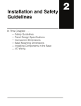
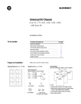
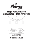
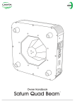
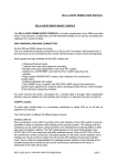
RMX-44 & RMX-62
™
™
MIXING MATRIX
Installation
&
Operation
Manual
TABLE OF CONTENTS
RMX-44 & RMX-62 INTRODUCTION ............................................................................................. 1
RMX-44 CALLOUTS ..................................................................................................................... 2
RMX-44 BLOCK DIAGRAM ........................................................................................................... 3
RMX-62 CALLOUTS ..................................................................................................................... 4
RMX-62 BLOCK DIAGRAM ........................................................................................................... 5
RMX-44 & RMX-62 SET-UP .......................................................................................................... 6
RMX-44 & RMX-62 SET-UP (CONTINUED) .................................................................................... 7
RMX-44 AUDIO & CONTROL PORT PIN ASSIGNMENTS ................................................................ 8
RMX-62 AUDIO & CONTROL PORT PIN ASSIGNMENTS ................................................................ 9
RMX-44 & RMX-62 APPLICATIONS ............................................................................................. 10
USER INSTALLATION & SET-UP NOTES ....................................................................................... 11
USER INSTALLATION & SET-UP NOTES ....................................................................................... 12
RMX-44 & RMX-62 SPECIFICATIONS .......................................................................................... 13
OXMOOR FACTORY SERVICE ...................................................................................................... 14
OXMOOR TWO YEAR LIMITED WARRANTY.................................................................................. 14
CONTACT OXMOOR .................................................................................................................... 14
RMX-44 & RMX-62 INTRODUCTION
• Front-panel input trimmers with +/- 15 dB gain adjustment
• Logic control port for setting various output configurations,
including a mix of the inputs
• Electronically balanced, XLR-type inputs and outputs
• +24 dBu input signal levels
• +24 dBm output signal levels
• Built-in RF suppression
• UL Listed
For enhanced flexibility on both units, each output driver can be set for balanced or unbalanced
operation using internal jumpers. The output
stages will deliver a +24 dBm maximum output
level, with overall 20Hz to 20 kHz frequency response, +0, -0.3 dB.
The RMX-44 and RMX-62 Mixing Matrixes may
be used as buffer/mixer/distribution amplifiers.
The RMX-44 offers a four-in by four-out configuration while the RMX-62 is a six-in by two-out
system. Each compact unit is housed in a 1U,
rackmount chassis and weighs just under 8.5
pounds.
Both devices are also available with optional output transformers. Designate Model RMX-44T or
Model RMX-62T. Transformer equipped version
may be operated Balanced or Unbalanced without any change to the internal jumpers.
The RMX-44 and RMX-62 are intended for use in
sound reinforcement, permanent installations,
playback, and other audio systems requiring
high-quality operation with flexible audio routing from remote locations.
Designed to satisfy exacting professional standards, the RMX-44 and RMX-62 offer excellent
performance in highly dependable packages.
Their impressive audio specifications are ideally
suited to recording and broadcast applications,
yet their rugged chassis and exceptional immunity to environmental stress make them an ideal
choice for demanding road work and commercial installations.
The RMX-44 unit allows, for example, stereo components and their sum to be assigned to separate
output lines. High and low input and output levels can also be freely intermixed without additional hardware, facilitating such common conversion tasks as interfacing hi-fi equipment with
professional audio systems.
The RMX-44 and RMX-62 input stages are electronically balanced and fitted with standard 3-pin,
XLR-type connectors. Front-panel gain trimmers
enable the installer to compensate for various input signal levels. RF suppression circuitry safeguards against radio-frequency interference in
hostile environments.
The RMX-44, RMX-44T, RMX-62, and RMX-62T
Mixing Matrixes are Underwriters Laboratories
(UL) Listed.
Page 1
RMX-44 CALLOUTS
4
4
1
OXMOOR
RMX-44 MIXING MATRIX
INPUT 1
INPUT 2
INPUT 3
INPUT 4
POWER
CHASSIS
PIN 2 POSITIVE ON ALL
AUDIO CONNECTIONS
CONTROL PORT
OUTPUT D
OUTPUT C
OUTPUT B
77
OUTPUT A
INPUT 4
INPUT 3
INPUT 2
FUSE
INPUT 1
2
2
8
8
99 9
SERIAL NUMBER
11
11
POWER
10
10
Figure 1.1: Front and Rear Panel Views of RMX-44
(Callouts refer to Figures 1.1, 1.2, and 1.3)
1. POWER LED - The front panel LED is illuminated
when the unit is on. The absence of an On/Off
switch is a performance safety feature, eliminating
accidental shutdown during operation.
2. INPUT CONNECTORS - XLR inputs, Pin 2 positive,
accept balanced or unbalanced signals from linelevel devices.
3. INPUT STAGE - The RF-suppressed input circuit is
electronically balanced (differential), and capable
of handling a maximum signal level of +24 dBu.
Balanced input impedance is approximately 80k
ohms, with a nominal input level range of -10 to
+8 dBu.
4. INPUT GAIN TRIM POTS - (labelled "INPUT 1,"
"INPUT 2,” etc.) Accessed through the front panel
with a small flat-blade screwdriver, these trim
pots adjust the input stage gain +/-15 dB, to
compensate for varying input signal levels.
5. OUTPUT STAGE - The output stage is electronically
balanced (push-pull) and AC coupled. Output
impedance is approximately 150 ohms. Each
output can provide a maximum level of +24 dBm
into a 600 ohm load, or +26 dBu unterminated.
7. OUTPUT CONNECTORS - XLR outputs, pin 2
positive, accommodate balanced or unbalanced
lines.
8. CONTROL PORT CONNECTOR - Female, 25-pin,
standard D-sub connector. Provides contacts for
jumpers or external switching to assign routing
of inputs to outputs. Latching contact closures
required (see SET-UP). Additional contacts
provide system mute capability and +15 VDC, 50
mA, output for powering LEDs, etc.
9. CHASSIS GROUND POST - Nuts on a threaded
stud enable the installer to conveniently secure a
ground wire to the chassis.
10. POWER CONNECTOR - Standard IEC 3-pin
connector for AC power cord. Use only with
grounded (3-wire) outlets. Cord sets are available
for all world connection standards.
11. FUSE HOLDER - Replace only with approved
type of fuse in a rating appropriate to the mains
voltage, as indicated on back panel (see
SPECIFICATIONS).
6. BALANCED/UNBALANCED JUMPER BLOCKS These permit each output to be unbalanced
independently, if necessary (see SET-UP).
Page 2
RMX-44 BLOCK DIAGRAM
22
33
1
4
4
55
6
6
7
7
2
1
2
INPUT 1
3
A
S
3
1
OUTPUT A
2
2
1
B
S
INPUT 2
3
3
OUTPUT B
1
1
2
2
C
S
3
INPUT 3
3
OUTPUT C
1
2
1
D
S
2
3
OUTPUT D
88
INPUT 4
3
CONTROL PORT
Figure 1.2: Block Diagram of RMX-44 Mixing Matrix
1
4
FRONT PANEL
6
REAR
PANEL
7
2
8
Figure 1.3: Interior View of RMX-44 Mixing Matrix
Page 3
11
10
9
RMX-62 CALLOUTS
4
1
OXMOOR
RMX-62 MIXING MATRIX
INPUT 1
INPUT 2
INPUT 3
INPUT 4
INPUT 5
INPUT 6
POWER
CHASSIS
PIN 2 POSITIVE ON ALL
AUDIO CONNECTIONS
CONTROL PORT
OUTPUT B
OUTPUT A
INPUT 6
7
INPUT 5
INPUT 4
INPUT 3
INPUT 2
INPUT 1
2
8
SERIAL NUMBER
FUSE
POWER
11
10
9
Figure 2.1: Front and Rear Panel Views of RMX-62
(Callouts refer to Figures 2.1, 2.2 and 2.3)
1. POWER LED - The front panel LED is illuminated
when the unit is on. The absence of an On/Off
switch is a performance safety feature, eliminating
accidental shutdown during operation.
2. INPUT CONNECTORS - XLR inputs, Pin 2 positive,
accept balanced or unbalanced signals from linelevel devices.
3. INPUT STAGE - The RF-suppressed input circuit is
electronically balanced (differential), and capable
of handling a maximum signal level of +24 dBu.
Balanced input impedance is approximately 80k
ohms, with a nominal input level range of -10 to
+8 dBu.
4. INPUT GAIN TRIM POTS - (labelled "INPUT 1,"
"INPUT 2,” etc.) Accessed through the front panel
with a small flat-blade screwdriver, these trim
pots adjust the input stage gain +/-15 dB, to
compensate for varying input signal levels.
7. OUTPUT CONNECTORS - XLR outputs, pin 2
positive, accommodate balanced or unbalanced
lines.
8. CONTROL PORT CONNECTOR - Female, 25 pin,
standard D-sub connector. Provides contacts for
jumpers or external switching needed to assign
routing of inputs to outputs. Latching contact
closures required (see SET-UP). Additional
contacts provide system mute capability and +15
VDC, 50 mA, output for powering LED's, etc.
9. CHASSIS GROUND POST - Nuts on a threaded stud
conveniently enable the installer to secure a
ground wire to the chassis.
10. POWER CONNECTOR - Standard IEC 3-pin
connector for AC power cord. Use only with
grounded (3-wire) outlets. Cord sets are available
for all world connection standards.
5. OUTPUT STAGE - The output stage is electronically
balanced (push-pull) and AC coupled. Output
impedance is approximately 150 ohms. Each
output can provide a maximum level of +24 dBm
into a 600 ohm load, or +26 dBu unterminated.
11. FUSE HOLDER - Replace only with approved
type of fuse in a rating appropriate to the mains
voltage, as indicated on back panel (see
SPECIFICATIONS).
6. BALANCED/UNBALANCED JUMPER BLOCKS These permit each output to be unbalanced
independently, if necessary (see SET-UP).
Page 4
RMX-62 BLOCK DIAGRAM
33
22
4
4
2
1
INPUT 1
3
2
1
55
6
6
7
7
INPUT 2
3
2
2
1
A
3
OUTPUT A
INPUT 3
3
1
S
2
1
2
INPUT 4
3
2
1
1
B
S
3
OUTPUT B
88
INPUT 5
3
CONTROL PORT
2
1
3
INPUT 6
Figure 2.2: Block Diagram of RMX-62 Mixing Matrix
1
4
FRONT PANEL
6
REAR
PANEL
7
2
8
Figure 2.3: Interior View of RMX-62 Mixing Matrix
Page 5
11
10
9
RMX-44 & RMX-62 SET-UP
The RMX-44 and RMX-62 may easily be configured
to meet your specific requirements. You may make
changes to the factory configuration of the unit in
two areas: outputs and inputs.
Each output has been configured at the factory to
be balanced. You may change each output independently to be unbalanced. This is the only set-up procedure that requires access to the chassis interior.
NOTE: If your unit has transformer coupled outputs (i.e., models RMX-44T or RMX-62T) no modification is required for unbalanced operation.
CAUTION:
Hazardous voltages are present inside
the chassis. Before opening the case to
gain access to the Balanced/Unbalanced
Jumpers, always remove the power from
the unit by disconnecting the AC cord.
Also, output connections are simplified by allowing the use of standard cables in all cases.
THE PROCEDURE:
1. Gain access to the inside of the chassis.
Each input may be assigned to any output or combination of outputs. Multiple inputs may also be
routed to each output.
CONVERTING OUTPUTS FROM BALANCED TO
UNBALANCED (ELECTRONICALLY BALANCED
OUTPUTS)
b. Remove the four screws that secure the
top cover and set the cover aside with the
screws.
2. Locate the Balanced/Unbalanced Jumper Block
next to the connector for the output you wish to
reconfigure. These are called out on Figures 1.3
If you wish to operate one or more of the outputs
unbalanced, you must follow this procedure. Setting the internal jumper correctly provides two benefits.
First, the possibility of shorting the corresponding
output driver to ground is eliminated. While an
output short will not harm the circuit, it may result
in increased distortion and crosstalk.
BALANCED
UNBALANCED
Each output is provided with an internal jumper;
the position of each jumper determines whether its
associated output is balanced (push-pull) or unbalanced. All outputs are balanced as delivered from
the factory. In the unbalanced configuration, pin 3
of the output connector is grounded, and the maximum output level drops by 6 dB.
a. Disconnect the power cord.
Rear
of
Chassis
Figure 3.1: Typical Balanced/Unbalanced Jumper Block
and 2.3.) The jumper is factory installed in the
balanced position.
3. Observing the positions shown in Figure 3.1 (and
marked on the circuit board), remove the jumper
and reinstall it in the unbalanced position.
4. Replace top cover and screws.
CONNECTOR WIRING FOR UNBALANCED
OUTPUT:
UNBALANCED
Pin 2 = "HOT"
Pin 3 = "COMMON"
Pin 1 = "SHIELD
Page 6
RMX-44 & RMX-62 SET-UP (CONTINUED)
(Please refer to Figures 3.2, 3.3, 3.4 and 3.5)
SOURCE TO OUTPUT ROUTING SELECTIONS
The signal source for each RMX-44 and RMX-62
output may be independently selected. You may
select one input per output (buffer), multiple inputs per output (mixer), or multiple outputs per
input (DA).
FIXED INPUT/OUTPUT
ROUTING CONFIGURATION
Inputs may be routed to outputs in a simple fixed
configuration using jumpers in a DB-25 male connector (supplied). The RMX-44 and RMX-62 come
supplied with a DB-25 male connector with jumpers soldered in place to provide a working, out-ofthe-box routing configuration. Merely inserting this
connector into the Control Port will assign the
audio sources to outputs as specified in Figures 3.2
and 3.4.
Alternative jumper positions between "common"
pins (numbers 1 through 3 and 14 through 16) and
others will provide alternate routing possibilities
as designated by their Assignment descriptions in
Figures3.3 and 3.5.
SELECTABLE INPUT/OUTPUT
ROUTING CONFIGURATION
Maximum flexibility of the RMX-44 and RMX-62
is realized, though, when the routing selection is
locally or remotely selectable. This is accomplished
through closure of external latching contacts (end
user provided). Each switch is used to close a circuit between two pins (one of them "common") of
the 25 pins available at the "control port" on the
rear of the chassis.
The logic inputs have an active low (CLOSURE TO
COMMON) type action and are provided with input protection. (See SPECIFICATIONS for details on
logic requirements.)
Any logic action must provide and maintain circuit
closure between common and appropriate control
lines to hold the internal switches for the routing
configuration desired.
Integral input isolation allows the logic inputs of
multiple units to be paralleled without any interaction between units or bus loading problems. No external pull-ups are required. A maximum of 64 control lines may be paralleled without affecting operation.
NOTE: If the CONTROL PORT is not configured,
all outputs on the RMX-44 and RMX-62 will be
muted.
ADDITIONAL CONTROL PORT PROVISIONS
SYSTEM MUTING
Closing a circuit between Pin 4 and common will
mute all channels. Muting will remain in effect as
long as the contact is close.
Muting may be desired during some paging operations or activated as an override function of a fire
alarm to kill background music, etc.
An external delay circuit may also be employed
to activate the MUTE function in order to lengthen
the two-second RMX-44/62 factory-set power-up
delay.
LOW VOLTAGE DC SUPPLY
Pins 13 and 25 are identical, paralleled DC outputs
providing +14 VDC at 50 mA. This supply may be
utilized to power LED indicators, etc.
The internal routing matrix is connected by individual control lines to the control port. This allows
any internal switch to be activated by directly accessing its control line without having to resort to
any binary/BCD type encoding.
Page 7
RMX-44 AUDIO & CONTROL PORT PIN ASSIGNMENTS
Input 1
Output A
Input 2
Output B
Input 3
Output C
Input 4
Output D
13
1
12
13
Control
Port
25
11
24
10
23
9
22
8
21
6
7
20
19
5
18
4
17
3
16
2
15
1
14
25
14
Figure 3.2: RMX-44 Factory Setup
CHASSIS
PIN 2 POSITIVE ON ALL
AUDIO CONNECTIONS
CONTROL PORT
OUTPUT D
OUTPUT C
OUTPUT B
OUTPUT A
INPUT 4
INPUT 3
INPUT 2
PIN NUMBER ASSIGNMENT
*
*
*
*
1
2
3
4
5
6
7
8
9
10
11
12
13
SERIAL NUMBER
FUSE
INPUT 1
POWER
PIN NUMBER ASSIGNMENT
Common
Common
Common
Mute
Input 4 to Output B
Input 3 to Output B
Input 2 to Output B
Input 1 to Output B
Input 4 to Output A
Input 3 to Output A
Input 2 to Output A
Input 1 to Output A
+15 VDC
*
*
*
*
14
15
16
17
18
19
20
21
22
23
24
25
Common
Common
Common
Input 4 to Output D
Input 3 to Output D
Input 2 to Output D
Input 1 to Output D
Input 4 to Output C
Input 3 to Output C
Input 2 to Output C
Input 1 to Output C
+15 VDC
Figure 3.3: RMX-44 Audio and Control Port Pin Assignments
* FACTORY SETUP: The RMX-44 is shipped from the factory with input 1 assigned to output A, input 2 to output B, input 3 to
output C, and input 4 to output D.
Page 8
RMX-62 AUDIO & CONTROL PORT PIN ASSIGNMENTS
Input 1
Output A
Input 2
Input 3
Input 4
Input 5
Output B
Input 6
13
1
13
Control
Port
12
25
11
24
10
23
9
22
8
21
6
7
20
5
19
18
4
17
3
16
2
15
1
14
25
14
Figure 3.4: RMX-62 Factory Setup
CHASSIS
PIN 2 POSITIVE ON ALL
AUDIO CONNECTIONS
CONTROL PORT
OUTPUT B
OUTPUT A
INPUT 6
INPUT 5
INPUT 4
INPUT 3
INPUT 2
PIN NUMBER ASSIGNMENT
*
*
*
*
*
*
1
2
3
4
5
6
7
8
9
10
11
12
13
SERIAL NUMBER
FUSE
INPUT 1
POWER
PIN NUMBER ASSIGNMENT
Common
Common
Common
Mute
Not Used
Not Used
Input 6 to Output A
Input 5 to Output A
Input 4 to Output A
Input 3 to Output A
Input 2 to Output A
Input 1 to Output A
+15 VDC
*
*
*
*
*
*
14
15
16
17
18
19
20
21
22
23
24
25
Common
Common
Common
Not Used
Not Used
Input 6 to Output B
Input 5 to Output B
Input 4 to Output B
Input 3 to Output B
Input 2 to Output B
Input 1 to Output B
+15 VDC
Figure 3.5: RMX-62 Audio and Control Port Pin Assignments
* FACTORY SETUP: The RMX-62 is shipped from the factory with inputs 1, 2 and 3 assigned to output A, and inputs 4, 5 and 6 to output B.
Page 9
RMX-44 & RMX-62 APPLICATIONS
AMPLIFIER
MIXER
ZONE A
Figure 4.1 shows a typical application
for the RMX-44. Each of four adjacent
hotel banquet/conference rooms is
equipped with an independent sound
reinforcement system.
ZONE A
AMPLIFIER
MIXER
ZONE B
ZONE B
AMPLIFIER
MIXER
ZONE C
ZONE C
AMPLIFIER
MIXER
ZONE D
ZONE D
Figure 4.1
RMX-44
Mixing Matrix
A single RMX-44 is inserted in the
path between all four mixers and
their respective power amplifiers.
As shown in Figure 4.2, each system
operates totally independent of the
other three.
AMPLIFIER
MIXER
ZONE A
ZONE A
AMPLIFIER
MIXER
ZONE B
ZONE B
AMPLIFIER
MIXER
The selectable input/output routing
feature of the RMX-44 makes it easy
to open the dividers between zones
A and B and use either or both of
their mixers to feed the amplifiers
and speakers in both areas as a single
system.
ZONE C
ZONE C
AMPLIFIER
MIXER
ZONE D
ZONE D
REMOTE PANEL
*
Figure 4.2
RMX-44
Mixing Matrix
MIXER
Zones C and D will continue to
operate as discrete systems (see
Figure 4.3). Combine any pair, any
three or all four rooms. Switches on
the control panel* close contacts
between appropriate pairs of pins on
the logic port, thus determining the
input/output routing.
ZONE A + B
MIXER
AMPLIFIER
ZONE B
ZONE B + A
MIXER
AMPLIFIER
ZONE C
ZONE C
MIXER
* control panel supplied by user
AMPLIFIER
ZONE A
AMPLIFIER
ZONE D
ZONE D
*REMOTE PANEL
Figure 4.3
Page 10
USER INSTALLATION & SET-UP NOTES
Page 11
USER INSTALLATION & SET-UP NOTES
Page 12
RMX-44 & RMX-62 SPECIFICATIONS
FREQUENCY RESPONSE
HUM AND NOISE
DISTORTION
CROSSTALK & OFF ISOLATION
INPUTS
OUTPUTS
TRIM POT GAIN RANGE
CONTROL PORT
TURN ON DELAY
MAINS POWER
MECHANICAL
20 Hz to 20 kHz ....................................... +0, -0.3 dB
-3 dB Points, Ref. 1 kHz ............................ 4 Hz to 70 kHz (+4 dBm Output)
Ref. +4 dBm Output @ Unity Gain ............. -85 dB (20 Hz to 20 kHz, Unweighted)
Total Harmonic (THD + NOISE)
Ref. +4 dBm Output @ Unity Gain ............. -80 dB/0.01% (20 Hz to 20 kHz)
Intermodulation (IMD)*
Ref. +4 dBm Output @ Unity Gain ............. -80 dB/0.01%
Channel to Channel** .............................. -80 dB (20 Hz to 20 kHz)
Driven Input to Off Output ......................... -80 dB (20 Hz to 20 kHz)
Type ....................................................... Electronically Balanced (RF Suppressed)
Connectors ............................................. Female XLR
Input Impedance ..................................... 80 k Ohms
Maximum Input Level ............................... +24 dBu
Type ....................................................... Electronically Balanced
Connectors ............................................. Male XLR
Source Impedance .................................. 150 Ohms (75 Ohms Each Side)
Recommended Load Impedance .............. 600 Ohms or Greater
Maximum Output Level
(Ref. 1 kHz @ rated THD)
Terminated w/600 Ohms .................... +24 dBm
Unterminated ...................................... +26 dBu
Ref. 0 dBu Output .................................... ±15 dB
Input Type ............................................... Active Low, Internally Pulled Up to +15VDC
Input Protection ....................................... 1/2 Max. Line Voltage, 12 kV Static
Logic Action ............................................. Requires Maintained Closure To Common
Connector ............................................... Female 25 Pin Std. D-Sub
Logic Levels (At Control Port) .................... Low < 3 Volts, High > 7 Volts
Maximum Paralleled Inputs ...................... 64
Maximum Sink Current ............................ 50 mA
Maximum Cable Length ........................... 600m (2000 ft), #22 AWG
Switching Time ........................................ 100 ms
Power Output .......................................... +15 VDC ±0.1 V, 50 mA
Power Up Delay ....................................... 2 sec ± 0.25 sec
Power Requirements ............................... 100 to 125 VAC or 200 to 230 VAC
50/60 Hz; 13 Watts Maximum
Fuse Type ............................................... 125 mA (1/8 amp) SB @ 115 VAC
63 mA (1/16 amp) SB @ 230 VAC
Overall Dimensions .................................. 44mm H x 482mm W x 183mm D
(1.72 in. H x 19 in. W x 7.18 in. D)
Finish ...................................................... Textured Black Paint
Weight .................................................... Shipping: 3.8 Kg (8.5 lb.) Net: 3.1 Kg (6.9 lb.)
ACCESSORIES
Supplied with unit .................................... One DB-25 Male Connector
UL LISTING
RMX-44 Mixing Matrix
RMX-44T Mixing Matrix
RMX-62 Mixing Matrix
RMX-62T Mixing Matrix
*SMPTE Method; 60 Hz + 7 kHz mixed 4:1.
** Input terminated w/600 ohms, unity gain, adjacent channel driven to +4 dBm output.
Specifications subject to change without notice.
Page 13
OXMOOR FACTORY SERVICE
For service information contact:
Oxmoor Product Service Department
309 Cahaba Valley Parkway
Birmingham, Alabama 35124
E-mail: [email protected]
Telephone: (205) 982-8200
Toll Free: 1 (800) 262-6898
Fax: (205) 982-8250
Internet: www.oxmoor.com
Additional Installation & Operation Manuals are available from Oxmoor. Contact the
Oxmoor Sales Department for pricing and other ordering information. Consult
warranty statement for cautions concerning unauthorized service.
OXMOOR TWO YEAR LIMITED WARRANTY
Oxmoor warrants that each Oxmoor electronic product shall be free from defects in workmanship
and materials and will, at its option, repair or replace any part of the product without charge
provided the product is delivered to Oxmoor within two years of date of original purchase from
or delivery by an authorized Oxmoor dealer. Excluded from this warranty are finish and
appearance items and malfunction resulting from abuse, from use that is not in accordance with
instructions, or operation under other than specified conditions. Also excluded are incidental or
consequential damages except where precluded by applicable law. This warranty provides the
customer with specific legal rights; there may also be other rights which vary from state to state.
Repair by other than Oxmoor Factory Service Department or its authorized service agency,
unauthorized modification, or the removal or defacing of the serial number will void this
warranty.
Products returned for factory warranty service must be prepaid and packaged in such a way as to
insure safe transit and must be accompanied by a sales slip or other valid proof of purchase date.
PRIOR AUTHORIZATION FROM OXMOOR IS REQUIRED FOR RETURN. Contact Oxmoor for
a Return Authorization (R.A.) Number and shipping information before returning product for
service.
CONTACT
OXMOOR
Oxmoor Corporation, LLC,
Toll Free 1 (800) 262-6898
309 Cahaba Valley Parkway,
Telephone (205) 982-8200
Birmingham, AL 35124 USA
Fax (205) 982-8250
E-mail [email protected]
For 24-hour access to product specs and information visit Oxmoor's complete product line on the internet at www.oxmoor.com.
Oxmoor is a registered trademark of Oxmoor Corporation, LLC.
Specifications and design are subject to change without notice.
Part Number:1700007
Oxmoor RMX-44 & RMX-62 Mixing Matrix
Rev. 2.4/072601