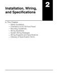
1
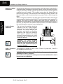
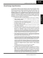
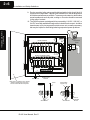
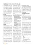
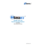
Installation and Safety Guidelines In This Chapter. . . . — Safety Guidelines — Panel Design Specifications — Component Dimensions — Base Mounting Dimensions — Installing Components in the Base — I/O Wiring 12 2--2 Installation and Safety Guidelines WARNING: Providing a safe operating environment for personnel and equipment is your responsibility and should be your primary goal during system planning and installation. Automation systems can fail and may result in situations that can cause serious injury to personnel or damage to equipment. Do not rely on the automation system alone to provide a safe operating environment. You should use external electromechanical devices, such as relays or limit switches, that are independent of the PLC system to provide protection for any part of the system that may cause personal injury or damage. Every automation application is different, so there may be special requirements for your particular application. Make sure you follow all National, State, and local government requirements for the proper installation and use of your equipment. Plan for Safety The best way to provide a safe operating environment is to make personnel and equipment safety part of the planning process. You should examine every aspect of the system to determine which areas are critical to operator or machine safety. If you are not familiar with PLC system installation practices, or your company does not have established installation guidelines, you should obtain additional information from the following sources. • NEMA — The National Electrical Manufacturers Association, located in Washington, D.C., publishes many different documents that discuss standards for industrial control systems. You can order these publications directly from NEMA. Some of these include: ICS 1, General Standards for Industrial Control and Systems ICS 3, Industrial Systems ICS 6, Enclosures for Industrial Control Systems • NEC — The National Electrical Code provides regulations concerning the installation and use of various types of electrical equipment. Copies of the NEC Handbook can often be obtained from your local electrical equipment distributor or your local library. S Local and State Agencies — many local governments and state governments have additional requirements above and beyond those described in the NEC Handbook. Check with your local Electrical Inspector or Fire Marshall office for information. Safety Techniques The publications mentioned provide many ideas and requirements for system safety. At a minimum, you should follow these regulations. Also, you should use the following techniques, which may help reduce the risk of safety concerns. • Orderly system shutdown sequence in the PLC control program. • System power disconnects (guard limits, emergency stop switches, etc.) Installation and Safety Guidelines Installation and Safety Guidelines Installation and Safety Guidelines Safety Guidelines DL305 User Manual, Rev. D 2--3 Installation and Safety Guidelines Three Levels of Protection Emergency Stops Guard Limit Switch E STOP Power On Emergency Stop Guard Limit Master Relay Master Relay Contacts Master Relay Contacts To disconnect PLC Power Master Relay Contacts Output Module To disconnect output module power DL305 User Manual, Rev. D Saw Arbor Installation and Safety Guidelines Use E-Stop and Master Relay Installation and Safety Guidelines The publications mentioned provide many ideas and requirements for system safety. At a minimum, you should follow these regulations. Using the techniques listed below will further help reduce the risk of safety problems. • Emergency stop switch for disconnecting system power. • Mechanical disconnect for output module power. • Orderly system shutdown sequence in the PLC control program. It is recommended that emergency stop circuits be incorporated into the system for every machine controlled by a PLC. For maximum safety in a PLC system, these circuits must not be wired into the controller, but should be hardwired external to the PLC. The emergency stop switches should be easily accessed by the operator and are generally wired into a master control relay (MCR) or a safety control relay (SCR) that will remove power from the PLC I/O system in an emergency. MCRs and SCRs provide a convenient means for removing power from the I/O system during an emergency situation. by de--energizing an MCR (or SCR) coil, power to the input (optional) and output devices is removed. This event occurs when any emergency stop switch opens. However, the PLC continues to receive power and operate even though all its inputs and outputs are disabled. The MCR circuit could be extended by placing a PLC fault relay (closed during normal PLC operation) in series with any other emergency stop conditions. This would cause the MCR circuit to drop the PLC I/O power in case of a PLC failure (memory error, I/O communications error. etc.). 2--4 Installation and Safety Guidelines Orderly System Shutdown Installation and Safety Guidelines Installation and Safety Guidelines Emergency Power Disconnect The first level of protection should be included in the PLC control program, which can be used to identify machine problems. You should analyze your application and identify any shutdown sequences that must be performed. These types of problems are usually things such as jammed parts, etc. that do not pose a risk of personal injury or equipment damage. WARNING: The control program should not be the only form of protection for any problems that may result in a risk of personal injury or equipment damage. Class 1, Division 2 Approval Installation and Safety Guidelines A properly rated emergency power disconnect should be used to power the PLC controlled system as ameans of removing the power from the entire control system. It may be necessary to install a capacitor across the disconnect to protect against a condition known as “outrush“. This condition occurs when the output triacs are turned off by powering off the disconnect, thus causing the energy stored in the inductive loads to seek the shortest distance to ground, which is often through the triacs. After an emergency shutdown or any other type of power interruption, there may be requirements that must be met before the PLC control program can be restarted. For example, there may be specific register values that must be established (or maintained from the state prior to the shutdown) before operations can resume. In this case, you may want to use retentive memory locations, or include constants in the control program to ensure a known starting point. Jam Detect Turn off Saw RST RST Retract Arm This equipment is suitable for use in Class 1, Division 2, groups A, B, C and D or non--hazardous locations only. WARNING: Explosion Hazard! Substitution of components may impair suitability for Class 1, Division 2. Do not disconnect equipment unless power has been switched off or area is known to be non--hazardous. DL305 User Manual, Rev. D Installation and Safety Guidelines 2--5 Panel Design Specifications DL305 User Manual, Rev. D Installation and Safety Guidelines 8. Installations where the ambient temperature may approach the lower or upper limits of the specifications should be evaluated properly. To do this place a temperature probe in the panel, close the door and operate the system until the ambient temperature has stabilized. If the ambient temperature is not within the operating specification for the DL305 system, measures such as installing a cooling/heating source must be taken to get the ambient temperature within the DL305 operating specifications. Installation and Safety Guidelines It is important to design your panel properly to help ensure the DL305 products operate within their environmental and electrical limits. Proper installation of your DL305 system requires an in-depth understanding of electrical control systems. The system installation should comply with the appropriate electrical codes and standards for your area. It is important that your system also conforms to the operating standards for the application to insure proper performance. The DL305 equipment should only be installed by personnel familiar with electrical/industrial applications. The DL305 installation should provide proper ventilation, spacing, and grounding to ensure the equipment will operate as specified. The diagram on the next page references the items in the following list. 1. The bases should be mounted horizontally to provide proper ventilation. 2. There should be a minimum of 7.2” (183mm) and a maximum of 13.75” (350mm) between bases. 3. A minimum clearance of 2” (50mm) between the base and the top, bottom and right side of the cabinet should be provided. 4. A minimum clearance of 3” (75mm) between the base and the left side of the cabinet should be provided. 5. There must be a minimum of 2” clearance between the panel door and the nearest DL305 component. 6. The ground terminal on the DL305 base must be connected to a single point ground. Copper stranded wire should be used for this connection to achieve a low impedance. Copper eye lugs should be crimped and soldered to the ends of the stranded wire to assure good surface contact. You should also remove anodized finishes and use copper lugs and star washers at termination points. A rule of thumb is to achieve a 0.1 ohm of DC resistance between the DL305 base and the single point of ground. 7. There must be a single point of ground (i.e. copper bus bar) for all devices in the panel requiring an earth ground return. The single point of ground must be connected to the panel ground termination. The panel ground termination must be connected to earth ground. For this connection you should use #12 AWG stranded copper wire as a minimum. Minimum wire sizes, color coding, and general safety practices should comply with appropriate electrical codes and standards for your area. A good common ground reference (Earth ground) is essential for proper operation of the DL305. The DL305 system and components are designed to operate with a common ground reference. There are several methods of providing an adequate common ground reference. These methods include: a) Installing a ground rod as close to the panel as possible. b) Connection to the incoming power system ground. 2--6 Installation and Safety Guidelines Installation and Safety Guidelines 9. Device mounting bolts and ground braid termination bolts should be #10 copper bolts or equivalent. Tapped holes instead of nut--bolt arrangements should be used whenever possible. To assure good contact on termination areas impediments such as paint, coating or corrosion should be removed in the area of contact. 10. The DL305 systems are designed to be powered by 110 VAC , 220 VAC, or 24 VDC normally available throughout an industrial environment. Isolation transformers and noise suppression devices are not normally necessary, but may be helpful in eliminating/reducing suspected power problems. 3” 75mm min. 2” 50mm min. DL305 CPU Base 2” 50mm min. Temperature Probe Power Source Installation and Safety Guidelines DL305 Local Expasion Base 2” 50mm min. Installation and Safety Guidelines 7.2” -- 13.75” 183 -- 350mm BUS Bar Earth Ground Note: there is a minimum of 2” (50mm) clearance between the panel door and the nearest DL305 component. Panel Ground Terminal Panel Component Chassis Star Washers DL305 User Manual, Rev. D Ground Braid Copper Lugs Star Washers Panel or Single Point Ground Installation and Safety Guidelines 2--7 In addition to the panel layout guidelines, there are other specifications that can affect the definition and installation of a PLC system. You should always consider the following areas whenever you install any PLC system. Environmental Specifications • Power Supply Specifications • Agency Approvals S Enclosure Selection and Component Dimensions The following table lists the environmental specifications that generally apply to the DL305 system (CPU, Bases I/O modules). I/O module operation may fluctuate depending on the ambient temperature and your application. Please refer to the appropriate I/O module chapters for the temperature derating curves applying to specific modules. Specification Rating Storage temperature --4° F to 158° F (--20° C to 70° C) 32° F to 140° F (0° C to 60° C) Ambient humidity 5% to 95% relative humidity (non--condensing) Vibration resistance MIL STD 810C, Method 514.2 Shock resistance MIL STD 810C, Method 516.2 Noise immunity NEMA (ICS3--304) 1 uS width rectangular wave Atmosphere No corrosive gases The power source must be capable of suppling voltage and current complying with the base power supply specifications. Specifications D3--05B D3--05BDC D3--08B D3--10B Input Voltage Range 100--240 VAC +10% / --15% 47--63Hz 20.5--30 VDC <10% ripple 100--240 VAC +10% / --15% 47--63Hz 100--240 VAC +10% / --15% 47--63Hz Base Power 70 VA max (46W) 48 Watts 70 VA max (57W) 70 VA max (57W) Inrush Current max. 30A 30A 30A 30A Dielectric Strength 1500VAC for 1 minute between terminals of AC P/S, Run output, Common, 24VDC 1500VAC for 1 minute between 24VDC input terminals and Run output 1500VAC for 1 minute between terminals of AC P/S, Run output, Common, 24VDC 2000VAC for 1 minute between terminals of AC P/S, Run output, Common, 24VDC Insulation Resistance >10MΩ at 500VDC >10MΩ at 500VDC >10MΩ at 500VDC >10MΩ at 500VDC Power Supply Output (Voltage Ranges and Ripple) (5VDC) 4.75--5.25V less than 0.1V p--p (5VDC) 4.75--5.25V less than 0.1V p--p (5VDC) 4.75--5.25V less than 0.1V p--p (5VDC) 4.75--5.25V less than 0.1V p--p (9VDC) 8.5--13.5V less than 0.2 V p--p (9VDC) 8.5--13.5V less than 0.2 V p--p (9VDC) 8.0--12.0V less than 0.2 V p--p (9VDC) 8.0--12.0V less than 0.2 V p--p (24VDC) 20--28V less than 1.2V p--p (24VDC) 20--28V less than 1.2V p--p (24VDC) 20--28V less than 1.2V p--p (24VDC) 20--28V less than 1.2V p--p Consumption DL305 User Manual, Rev. D Installation and Safety Guidelines Power Ambient operating temperature Installation and Safety Guidelines Environmental Specifications • Installation and Safety Guidelines Agency Approvals Some applications require agency approvals. Typical agency approvals which your application may require are: • UL (Underwriters’ Laboratories, Inc.) • CSA (Canadian Standards Association) • FM (Factory Mutual Research Corporation) S CUL (Canadian Underwriters’ Laboratories, Inc.) Enclosures Your selection of a proper enclosure is important to ensure safe and proper operation of your DL305 system. Applications of DL305 systems vary and may require additional features. The minimum considerations for enclosures include: • Conformance to electrical standards • Protection from the elements in an industrial environment • Common ground reference • Maintenance of specified ambient temperature • Access to equipment • Security or restricted access S Sufficient space for proper installation and maintenance of equipment Component Dimensions Before installing your PLC system you will need to know the dimensions for the components in your system. The diagrams on the following pages provide the component dimensions and should be used to define your enclosure specifications. Remember to leave room for potential expansion. Appendix D provides the weights for each component. Installation and Safety Guidelines Installation and Safety Guidelines Installation and Safety Guidelines 2--8 DL305 User Manual, Rev. D 2--9 Installation and Safety Guidelines 11.41” 290mm 5 slot base .94” 24mm 10.63” 270mm Handheld Programer on side view of Base 3.54” 90mm 4.84” 123mm 4.41” 112mm 15.55” 395mm 8 slot base 5.35” 136mm 14.76” 375mm Installation and Safety Guidelines 3.54” 90mm 4.84” 123mm 18.30” 465mm 10 slot base 17.51” 445mm 3.54” 90mm 4.84” 123mm 4.92’ 1.5m 1.6’ 0.5m 1.15” 29.9 mm 1.37” 34.8mm Handheld programmer CPU 4.33” 110mm 3.86” 96mm 4.67” 118.6mm 4.65” 118mm DL305 User Manual, Rev. D .94” 24mm Installation and Safety Guidelines Handheld programmer cable I/O Expander cable 2--10 Installation and Safety Guidelines Component Dimensions Part 2 I/O modules 1.37” 34.8mm 4.65”/118nn -- 8 I/O Pts 4.86”/123mm -- 16 I/O Pts 4.67” 118.6mm Installation and Safety Guidelines .55” 14mm I/O module w/24 pin connector 1.37” 34.8mm 24 pin connector 3.86” 98mm Installation and Safety Guidelines Installation and Safety Guidelines 3.86” 98mm 2.00” 51mm 2.06” 52.4mm 4.84” 123mm 1.85” 47mm 0.51” 13mm 0.4” 10.3mm Data communication units (Prom Writer Unit has the same dimensions) 4.33” 110mm 4.65” 118mm DL305 User Manual, Rev. D 1.5” 38mm Installation and Safety Guidelines 2--11 Base Mounting Dimensions Below are the mounting dimensions which should be used when mounting DL305 bases. Make sure you have followed the installation guidelines for proper spacing. 5 slot base 11.41” 290mm .94” 24mm 10.63” 270mm Handheld Programer on side view of Base 3.54” 90mm 4.84” 123mm 14.76” 375mm 3.54” 90mm 4.84” 123mm 17.51” 445mm 3.54” 90mm 4.84” 123mm Installing Components in the Base When inserting components into the base, align the PC board(s) of the module with the grooves on the top and bottom of the base. Push the module straight into the base until it is firmly seated in the backplane connector. Align module to slots in base and slide in DL305 User Manual, Rev. D Installation and Safety Guidelines 18.30” 465mm 10 slot base Installation and Safety Guidelines 8 slot base 4.41” 112mm 5.35” 136mm 15.55” 395mm 2--12 Installation and Safety Guidelines The following diagram shows the terminal connections located on the power supply of the DL305 bases. Base Wiring WARNING: Damage will occur to the base power supply if 220 VAC is connected to the 115 VAC terminal connections. Once the power wiring is connected, install the protective cover. When the cover is removed there is a risk of electrical shock if you accidentally touch the connection terminals. 24 VDC Terminal Strip Installation and Safety Guidelines Installation and Safety Guidelines 110/220 VAC Terminal Strip Line Neutral Expansion Base Wiring This is an example of how to connect power when using local CPU and Expansion bases. Installation and Safety Guidelines 110VAC Line 220VAC 24VDC + -- Neutral 110VAC 220VAC 24VDC + -- Local CPU Local CPU Local CPU 110VAC 220VAC 24VDC + -- Expansion Base 1 Expansion Base 1 Expansion Base 1 110VAC 220VAC 24VDC + -- Expansion Base 2 Expansion Base 2 Expansion Base 2 DL305 User Manual, Rev. D Installation and Safety Guidelines 2--13 I/O Wiring This information provides a general idea on how to wire the different types of modules in the DL305 system. For specific information on wiring a particular module refer to the specification sheet in the appropriate I/O chapter or manual. I/O Wiring Guidelines Module type Maximum AWG 8 point 12 16 point 16 DL305 User Manual, Rev. D Installation and Safety Guidelines 2. Always use a continuous length of wire, do not combine wires to attain a needed length. 3. Use the shortest possible cable length. 4. Use wire trays for routing where possible 5. Avoid running wires near high energy wiring. 6. Avoid running input wiring in close proximity to output wiring where possible. 7. To minimize voltage drops when wires must run a long distance , consider using multiple wires for the return line. 8. Avoid running DC wiring in close proximity to AC wiring where possible. 9. Avoid creating sharp bends in the wires. Installation and Safety Guidelines You should consider these guidelines when wiring your system. 1. There is a limit to the size of wire the modules can accept. The table below lists the maximum AWG for each module type. Smaller AWG is acceptable to use for each of the modules. 2--14 Installation and Safety Guidelines WARNING: For some modules, field device power may still be present on the terminal block even though the PLC system is turned off. To minimize the risk of electrical shock, check all field device power before you remove the connector. Squeeze Tab Squeeze Tab D--shell Connector Installation and Safety Guidelines Installation and Safety Guidelines Installation and Safety Guidelines Wiring the Different There are three main types of module faces for the DL305 I/O. These module faces are: lift covers over terminal blocks, flip covers over terminal blocks and D--shell Module Types compatible sockets. If the module you are using has a cover you can remove the cover either by lifting from the bottom or by flipping the door open. Some of the modules have removable terminal blocks. These modules can be recognized by the squeeze tabs on the top and bottom of the terminal block. To remove the terminal block, press the squeeze tabs and pull the terminal block away from the module. DL305 User Manual, Rev. D Removable Cover Removable Terminal Block