1
2
Operation and Features
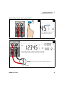
Measuring Low-Resistance
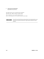
CAUTION
NOTE
Disconnect circuit power and discharge all high-voltage capacitors
before measuring resistance or conductance, or testing circuit
continuity, to avoid damaging the U3606B or the device under test.
DC power supply functions are locked
The DC power supply functions are locked when you select the
low-resistance (Lo Ω) measurements. You cannot use the DC power
supply module simultaneously with the digital multimeter module when
you are measuring 4-wire low-resistance measurements.
To unlock the DC power supply functions, exit the low-resistance (Lo Ω)
measurement by selecting another multimeter measurement.
NOTE
Delayed response for low-resistance readings
For measuring low-resistance, a delayed response should be expected
from the front panel display. For remote interface operation, increase the
SCPI query time-out value (typically 15000 ms).
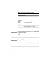
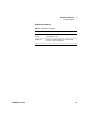
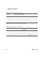
Low-resistance measurement summary
Table 2-5 Low-resistance measurement summary
44
Item
Description
Available ranges
100 mΩ, 1000 mΩ, 10 Ω, 100 Ω, 1000 Ω
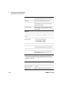
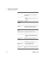
Measurement
method
Four-wire, the test current is sent from the FORCE
terminals and the resistance is measured by the SENSE
terminals.
Input protection
• FORCE terminals: Protected with a 3.15 A/250 V FF fuse
• SENSE terminals: 1000 Vrms on all ranges, < 0.3 A short
circuit
U3606B User’s Guide