Download User`s Guide

Transcript
Keysight U1271A/U1272A
Handheld Digital Multimeter
User’s Guide
Notices
© Keysight Technologies 2010 - 2014
Warranty
No part of this manual may be reproduced in
any form or by any means (including electronic storage and retrieval or translation
into a foreign language) without prior agreement and written consent from Keysight
Technologies as governed by United States
and international copyright laws.
The material contained in this document is
provided “as is,” and is subject to change,
without notice, in future editions. Further,
to the maximum extent permitted by the
applicable law, Keysight disclaims all
warranties, either express or implied, with
regard to this manual and any information
contained herein, including but not limited
to the implied warranties of merchantability and fitness for a particular purpose.
Keysight shall not be liable for errors or for
incidental or consequential damages in
connection with the furnishing, use, or
performance of this document or of any
information contained herein. Should Keysight and the user have a separate written
agreement with warranty terms covering
the material in this document that conflict
with these terms, the warranty terms in
the separate agreement shall control.
Manual Part Number
U1271-90010
Edition
Edition 12, December 22, 2014
Keysight Technologies
1400 Fountaingrove Parkway
Santa Rosa, CA 95403
Technology Licenses
The hardware and or software described in
this document are furnished under a license
and may be used or copied only in accordance with the terms of such license.
Restricted Rights Legend
U.S. Government Restricted Rights. Software and technical data rights granted to
the federal government include only those
rights customarily provided to end user customers. Keysight provides this customary
commercial license in Software and technical data pursuant to FAR 12.211 (Technical
Data) and 12.212 (Computer Software) and,
for the Department of Defense, DFARS
252.227-7015 (Technical Data - Commercial
Items) and DFARS 227.7202-3 (Rights in
Commercial Computer Software or Computer Software Documentation).
U1271A/U1272A User’s Guide
Safety Notices
CAUTION
A CAUTION notice denotes a hazard. It calls attention to an operating procedure, practice, or the likes
of that, if not correctly performed
or adhered to, could result in damage to the product or loss of
important data. Do not proceed
beyond a CAUTION notice until the
indicated conditions are fully
understood and met.
WA R N I N G
A WARNING notice denotes a
hazard. It calls attention to an
operating procedure, practice, or
the likes of that, if not correctly
performed or adhered to, could
result in personal injury or death.
Do not proceed beyond a WARNING notice until the indicated
conditions are fully understood
and met.
3
Safety Symbols
The following symbols on the instrument and in the documentation
indicate precautions which must be taken to maintain safe operation of
the instrument.
Direct current (DC)
Caution, risk of electric shock
Alternating current (AC)
Caution, risk of danger (refer to this manual
for specific Warning or Caution information)
Both direct and alternating current
CAT III
1000 V
Category III 1000 V overvoltage protection
Earth (ground) terminal
CAT IV
600 V
Category IV 600 V overvoltage protection
Equipment protected throughout by
double insulation or reinforced
insulation
4
Caution, risk of hazardous voltage (icon
appears on the instrument screen)
U1271A/U1272A User’s Guide
Safety Considerations
Read the information below before using this multimeter. The descriptions
and instructions in this manual apply to the Keysight U1271A and U1272A
Handheld Digital Multimeters (hereafter referred to as the multimeter).
The model U1272A appears in all illustrations.
CAUTION
• Disconnect circuit power and discharge all high-voltage capacitors
before testing resistance, continuity, diodes, or capacitance.
• Use the proper terminals, function, and range for your
measurements.
• This device is for use at altitudes of up to 2,000 m.
• Never measure voltage when current measurement is selected.
• Always use the specified battery type. The power for the meter is
supplied with four standard AAA 1.5 V batteries. Observe the
correct polarity markings before you insert the batteries to ensure
proper insertion of the batteries in the meter.
• You are advised to use low leakage batteries when changing to new
batteries. Please remember to remove the batteries when the meter
is not in use for a long period of time. Warning on the risk of battery
leakage.
WA R N I N G
• Do not use the multimeter if it is damaged. Before you use the
multimeter, inspect the case. Look for cracks or missing plastic.
Pay particular attention to the insulation surrounding the
connectors.
• Inspect the test leads for damaged insulation or exposed metal.
Check the test leads for continuity. Replace damaged test leads
before you use the multimeter.
• Do not operate the multimeter around explosive gas, vapor, or wet
environments.
• Do not apply more than the rated voltage (as marked on the
multimeter) between terminals, or between terminal and earth
ground.
U1271A/U1272A User’s Guide
5
WA R N I N G
• Never use the multimeter in wet conditions or when there is
water on the surface. If the multimeter is wet, ensure that the
multimeter is dried only by trained personnel.
• Before use, verify the multimeter's operation by measuring a
known voltage.
• When measuring current, turn off the circuit power before
connecting the multimeter in the circuit. Remember to place the
multimeter in series with the circuit.
• When servicing the multimeter, use only the specified
replacement parts.
• Use caution when working above 60 V DC, 30 V AC RMS, or 42.4 V
peak. Such voltages pose a shock hazard.
• Be aware of the presence of hazardous AC voltage before using
the Low Pass Filter (LPF) function for AC voltage measurement.
Voltages measured are usually greater than what indicated on the
multimeter as the AC voltages with higher frequencies have been
filtered through the LPF function.
• Do not use the ZLOW (low input impedance) function (U1272A
only) to measure voltages in circuits that could be damaged by
this function’s low input impedance of 2 kΩ.
• When using the probes, keep your fingers behind the finger
guards on the probes.
• Connect the common test lead before you connect the live test
lead. When you disconnect the leads, disconnect the live test lead
first.
• Remove the test leads from the multimeter before you open the
battery cover.
• Do not operate the multimeter with the battery cover or portions
of the cover removed or loosened.
• To avoid false readings, which may lead to possible electric shock
or personal injury, replace the battery as soon as the low battery
indicator appears and flashes.
6
U1271A/U1272A User’s Guide
Environmental Conditions
This instrument is designed for indoor use and in an area with low
condensation. The table below shows the general environmental
requirements for this instrument.
NOTE
U1271A/U1272A User’s Guide
Environmental conditions
Requirements
Operating temperature
Full accuracy from –20 °C to 55 °C
Operating humidity
Full accuracy up to 80% RH (relative
humidity) for temperature up to 30 °C,
decreasing linearly to 50% RH at 55 °C
Storage temperature
–40 °C to 70 °C
Altitude
Up to 2000 meters
Pollution degree
Pollution degree II
The U1271A/U1272A Handheld Digital Multimeter complies with the following
safety and EMC requirements:
• EN/IEC 61010-1:2001
• ANSI/UL 61010-1:2004
• CAN/CSA-C22.2 No. 61010-1-04
• Commercial limits compliance with EN61326-1
7
Regulatory Markings
8
The CE mark is a registered trademark
of the European Community. This CE
mark shows that the product complies
with all the relevant European Legal
Directives.
The C-tick mark is a registered
trademark of the Spectrum
Management Agency of Australia. This
signifies compliance with
the Australia EMC Framework
regulations under the terms of the
Radio Communication Act of 1992.
ICES/NMB-001 indicates that this ISM
device complies with the Canadian
ICES-001.
Cet appareil ISM est confomre a la
norme NMB-001 du Canada.
This instrument complies with the
WEEE Directive (2002/96/EC) marking
requirement. This affixed product label
indicates that you must not discard
this electrical or electronic product in
domestic household waste.
The CSA mark is a registered
trademark of the Canadian Standards
Association.
This symbol indicates the time period
during which no hazardous or toxic
substance elements are expected to
leak or deteriorate during normal use.
Forty years is the expected useful life
of the product.
U1271A/U1272A User’s Guide
Waste Electrical and Electronic Equipment (WEEE) Directive 2002/96/EC
This instrument complies with the WEEE Directive (2002/96/EC) marking
requirement. This affixed product label indicates that you must not discard
this electrical or electronic product in domestic household waste.
Product Category:
With reference to the equipment types in the WEEE directive Annex 1, this
instrument is classified as a “Monitoring and Control Instrument” product.
The affixed product label is as shown below.
Do not dispose in domestic household waste.
To return this unwanted instrument, contact your nearest Keysight Service
Centre, or visit
www.keysight.com/environment/product
for more information.
U1271A/U1272A User’s Guide
9
Declaration of Conformity (DoC)
The Declaration of Conformity (DoC) for this instrument is available on the
Keysight Web site. You can search the DoC by its product model or
description at the Web address below.
http://regulations.products.keysight.com/DoC/search.htm
NOTE
10
If you are unable to search for the respective DoC, please contact your
local Keysight representative.
U1271A/U1272A User’s Guide
Table of Contents
1
Introduction
About This Manual 22
Documentation map 22
Safety notes 22
Preparing Your Multimeter 23
Check the shipment 23
Install the batteries 23
Turn on your multimeter 26
Automatic power-off 26
Enabling the backlight 27
Selecting the range 27
Alerts and warnings during measurement
Adjusting the tilt stand 30
Connecting the IR-USB cable 30
Power-on options 32
Your Multimeter in Brief
Dimensions 33
Overview 35
Rotary switch 37
Keypad 41
Display screen 45
Input terminals 51
Cleaning Your Multimeter
2
28
33
53
Making Measurements
Crest Factor
56
Measuring AC Voltage 57
Using the LPF (Low Pass Filter) Function for AC
measurements 59
U1271A/U1272A User’s Guide
11
Measuring DC Voltage 60
Using the Filter Function for DC measurement
63
Measuring AC and DC Signals (U1272A only) 64
Using the LPF (Low Pass Filter) Function for AC+DC
measurements 65
Making dB Measurements (U1272A only)
66
Using ZLOW for Voltage Measurements (U1272A only)
68
Using Qik-V for Voltage Measurements (U1271A only)
70
Measuring Resistance
71
Measuring Conductance
Testing for Continuity
73
74
Using Smart Ω for Resistance Measurements (U1272A only)
Testing Diodes
77
80
Using Auto-diode for Diode Tests (U1272A only)
Measuring Capacitance
86
Measuring Temperature
88
Measuring AC or DC Current 93
% Scale of 4-20 mA or 0-20 mA
84
98
Frequency Test Mode 101
Measuring frequency 102
Measuring pulse width 104
Measuring duty cycle 105
3
Multimeter Features
Making Relative Measurements (Null)
Making Scale Transfers (Scale)
108
110
Capturing Maximum and Minimum Values (MaxMin)
12
112
U1271A/U1272A User’s Guide
Capturing Peak Values (Peak)
114
Freezing the Display (TrigHold and AutoHold)
115
Recording Measurement Data (Data Logging)
Performing manual logs (HAnd) 117
Performing interval logs (AUto) 118
Performing event logs (triG) 120
116
Reviewing Previously Recorded Data (View)
4
122
Multimeter Setup Options
Using the Setup Menu 126
Editing numerical values 127
Setup Menu Summary
128
Setup Menu Items 130
Changing the beep frequency 130
Enabling and disabling the Filter 131
Changing the variation count 133
Changing the recording option 134
Changing the sample interval duration 135
Changing the decibel display (U1272A only) 136
Setting a custom dBm reference impedance (U1272A
only) 137
Changing the auto power-off and backlight timeouts 138
Enabling and disabling the overvoltage alert 140
Changing the % scale range 141
Changing the thermocouple type (U1272A only) 142
Changing the minimum measurable frequency 143
Changing the baud rate 144
Changing the data bits 145
Changing the parity check 146
Enabling and disabling the backlight alert 147
Enabling smooth mode 148
U1271A/U1272A User’s Guide
13
Changing the user scale conversion value and unit
Resetting the multimeter’s setup options 150
Changing the temperature unit 151
5
149
Characteristics and Specifications
Product Characteristics
Specification Assumptions
154
156
Measurement Category 156
Measurement category definition
156
Electrical Specifications 158
DC specifications 158
AC specifications 161
AC+DC specifications for U1272A 165
Capacitance specifications 167
Temperature specifications 168
Frequency specifications 169
Duty cycle and pulse width specifications 169
Frequency sensitivity specifications 171
Peak hold specifications 172
Decibel (dB) specifications for U1272A 173
Measurement rate (approximate) 174
14
A
Shift Functions Using the Shift Key
B
Dual Display Combinations Using the Dual Key
U1271A/U1272A User’s Guide
List of Figures
Figure 1-1
Figure 1-2
Figure 1-3
Figure 1-4
Figure 1-5
Figure 1-6
Figure 1-7
Figure 1-8
Figure 1-9
Figure 1-10
Figure 1-11
Figure 1-12
Figure 1-13
Figure 1-14
Figure 2-1
Figure 2-2
Figure 2-3
Figure 2-4
Figure 2-5
Figure 2-6
Figure 2-7
Figure 2-8
Figure 2-9
Figure 2-10
Figure 2-11
Figure 2-12
Figure 2-13
Figure 2-14
Figure 2-15
Figure 2-16
Figure 2-17
Figure 2-18
Figure 2-19
Figure 2-20
U1271A/U1272A User’s Guide
Installing the batteries 24
Start-up display 26
Input warning display 29
Tilt-stand adjustment and IR cable connection 30
Keysight GUI Data Logger Software 31
Width dimensions 33
Height and depth dimensions 34
Front panel 35
Rear panel 36
U1271A rotary switch 38
U1272A rotary switch 39
Keys 41
Display screen 45
Connector terminals 51
AC voltage display 57
Measuring AC voltage 58
AC voltage with LPF display 59
DC voltage display 60
Measuring DC voltage 62
Filter for DC voltage measurements 63
AC+DC voltage display 64
Low Pass Filter(LPF) for AC+DC voltage
measurements 65
dBm display 66
dBV display 67
ZLOW display 69
Qik-V display 70
Resistance display 71
Measuring resistance 72
Continuity operation 75
Testing for continuity 76
Smart Ω (with bias voltage) display 78
Measuring leakage current 79
Diode display 80
Open diode display 81
15
Figure 2-21
Figure 2-22
Figure 2-23
Figure 2-24
Figure 2-25
Figure 2-26
Figure 2-27
Figure 2-28
Figure 2-29
Figure 2-30
Figure 2-31
Figure 2-32
Figure 2-33
Figure 2-34
Figure 2-35
Figure 2-36
Figure 2-37
Figure 2-38
Figure 2-39
Figure 2-40
Figure 3-1
Figure 3-2
Figure 3-3
Figure 3-4
Figure 3-5
Figure 3-6
Figure 3-7
Figure 3-8
Figure 3-9
Figure 3-10
Figure 4-1
Figure 4-2
Figure 4-3
Figure 4-4
Figure 4-5
Figure 4-6
16
Testing forward bias diode 82
Testing reverse bias diode 83
Auto-diode display - Good status 85
Auto-diode display - nGood status 85
Capacitance display 86
Measuring capacitance 87
Temperature display 88
Measuring surface temperature 89
Temperature measurement without ambient
compensation 92
DC current display 94
Measuring DC current 95
Measuring AC current 96
Current measurement setup 97
4-20 mA % Scale display 98
Measuring DC current using the 4-20 mA % scale 100
Functions allowing frequency measurement 101
Frequency, pulse width, and duty cycle
measurements 102
Frequency display 103
Pulse width display 104
Duty cycle display 105
Null display 108
Null operation 109
Scale operation 111
MaxMin display 113
Peak display 114
Manual log display 117
Interval log display 119
Event log display 121
View display 122
Empty view display 122
bEEP display 130
FiLtEr display 133
AHOLd display 134
d-LoG display 135
L-tiME display 136
dCibEL display 137
U1271A/U1272A User’s Guide
Figure 4-7
Figure 4-8
Figure 4-9
Figure 4-10
Figure 4-11
Figure 4-12
Figure 4-13
Figure 4-14
Figure 4-15
Figure 4-16
Figure 4-17
Figure 4-18
Figure 4-19
Figure 4-20
Figure 4-21
U1271A/U1272A User’s Guide
dbrEF display 138
APo display 139
bLit display 139
ALErt display 140
PErCEn display 141
CoUPLE display 142
FrEq display 143
bAUd display 144
dAtAb display 145
PAritY display 146
A-bLit display 147
SMootH display 148
SMootH display 149
rESEt display 150
t-Unit display 151
17
THIS PAGE HAS BEEN INTENTIONALLY LEFT BLANK.
18
U1271A/U1272A User’s Guide
List of Tables
Table 1-1
Table 1-2
Table 1-3
Table 1-4
Table 1-5
Table 1-6
Table 1-7
Table 1-8
Table 1-9
Table 1-10
Table 1-11
Battery level indicator 25
Power-on options 32
Front panel parts 35
Rear panel parts 36
U1271A rotary switch functions 38
U1272A rotary switch functions 39
Keypad functions 42
General annunciators 45
Measurement units display 49
Analog bar graph display 50
Terminal connections for different measuring
functions 52
Table 2-1 Threshold resistance values 74
Table 2-2 Auto-diode voltage thresholds 84
Table 2-3 % Scale measurement range 99
Table 3-1 Available scale conversions 110
Table 3-2 Data logging maximum capacity 116
Table 3-3 Event log trigger conditions 120
Table 4-1 Setup menu key functions 126
Table 4-2 Setup menu item descriptions 128
Table 4-3 Filter (LPF) options 132
Table 4-4 Firmware version 2.00 or older 132
Table 4-5 Firmware version 2.04 or newer 132
Table 5-1 DC specifications 158
Table 5-2 U1271A true rms AC voltage specifications 161
Table 5-3 U1271A true rms AC current specifications 162
Table 5-4 U1272A true rms AC voltage specifications 163
Table 5-5 U1272A true rms AC current specifications 164
Table 5-6 U1272A true rms AC+DC voltage specifications 165
Table 5-7 U1272A true rms AC+DC current specifications 166
Table 5-8 Capacitance specifications 167
Table 5-9 Temperature specifications 168
Table 5-10 Frequency specifications 169
Table 5-11 Duty cycle and pulse width specifications 169
Table 5-12 Duty cycle and pulse width calculation example 170
U1271A/U1272A User’s Guide
19
Table 5-13 Frequency sensitivity and trigger level specifications for
voltage measurements 171
Table 5-14 Frequency sensitivity specifications for current
measurements 171
Table 5-15 Peak hold specifications for DC voltage and current
measurements 172
Table 5-16 U1272A decibel specifications 173
Table 5-17 U1272A decibel accuracy specifications for DC voltage
measurements 173
Table 5-18 Measurement rate (approximate) 174
Table A-1 U1271A default and shift functions 176
Table A-2 U1272A default and shift functions 177
Table B-1 U1271A dual display combinations 180
Table B-2 U1272A dual display combinations 182
20
U1271A/U1272A User’s Guide
U1271A/U1272A Handheld Digital Multimeter
User’s Guide
1
Introduction
About This Manual 22
Documentation map 22
Safety notes 22
Preparing Your Multimeter 23
Check the shipment 23
Install the batteries 23
Turn on your multimeter 26
Automatic power-off 26
Enabling the backlight 27
Selecting the range 27
Alerts and warnings during measurement 28
Adjusting the tilt stand 30
Connecting the IR-USB cable 30
Power-on options 32
Your Multimeter in Brief 33
Dimensions 33
Overview 35
Rotary switch 37
Keypad 41
Display screen 45
Input terminals 51
Cleaning Your Multimeter 53
This chapter lists the package contents for each multimeter
model, and teaches you how to set up your multimeter for
the first time. An introduction to all the features of the
multimeter is also given. This introduction does not cover all
of the capabilities of the multimeter but gives basic examples
to help you perform basic operations on your multimeter.
1
Introduction
About This Manual
About This Manual
Documentation map
The following manuals and software are available for your
multimeter. For the very latest version, please visit our Web
site at: http://www.keysight.com/find/hhTechLib.
Check the manual revision on the first page of each manual.
• User’s Guide. This manual.
• Quick Start Guide. Printed copy for outdoor use,
included with shipment.
• Service Guide. Free download at the Keysight Web site.
• Keysight GUI Data Logger Software, Help, and Quick
Start Guide. Free download at the Keysight Web site.
Safety notes
The following safety notes are used throughout this manual.
Familiarize yourself with each of the notes and its meaning
before operating your multimeter. More pertinent safety
notes for using this product are located under the “Safety
Symbols” section.
22
CAUTION
Caution denotes a hazard. It calls attention to a procedure that, if not
correctly performed or adhered to, could result in damage to or
destruction of the product. Do not proceed beyond a caution notice
until the indicated conditions are fully understood and met.
WA R N I N G
Warning denotes a hazard. It calls attention to a procedure which, if
not correctly performed or adhered to, could result in injury or loss of
life. Do not proceed beyond a warning note until the indicated
conditions are fully understood and met.
U1271A/U1272A User’s Guide
Introduction
Preparing Your Multimeter
1
Preparing Your Multimeter
Check the shipment
When you receive your multimeter, check the shipment
according to the following procedure.
1 Inspect the shipping container for damage. Signs of
damage may include a dented or torn shipping container
or cushioning material that indicates signs of unusual
stress or compacting. Save the packaging material in case
the multimeter needs to be returned.
2 Carefully remove the contents from the shipping
container, and verify that the standard accessories and
your ordered options are included in the shipment
according to the Included Accessories list located at the
side of the box.
3 For any question or problems, refer to the Keysight
contact numbers on the back of this manual.
Install the batteries
Your multimeter is powered by four 1.5 V AAA alkaline
batteries (included with the shipment). When you receive
your multimeter, the AAA alkaline batteries are not
installed.
Use the following procedure to install the batteries.
CAUTION
Before you proceed with the batteries installation, remove all cable
connections to the terminals and ensure that the rotary switch is at the
OFF position. Use only the battery type specified in the “Product
Characteristics” on page 154.
U1271A/U1272A User’s Guide
23
1
Introduction
Preparing Your Multimeter
1 Open the battery cover. Lift the tilt stand and loosen the
screws with a suitable Phillips screwdriver and remove
the battery cover as shown in Figure 1- 1.
2 Insert the battery. Observe the proper battery polarity.
The terminal ends of each battery are indicated inside the
battery compartment.
3 Close the battery cover. Place the battery cover back in
its original position and tighten the screws.
1
2
3
Figure 1-1 Installing the batteries
The battery level indicator in the lower left- hand corner of
the display indicates the relative condition of the batteries.
Table 1- 1 describes the various battery levels the indicator
represents.
24
U1271A/U1272A User’s Guide
Introduction
Preparing Your Multimeter
1
Table 1-1 Battery level indicator
Indication
Battery capacity
Full capacity
2/3 capacity
1/3 capacity
(Flashing periodically)
Almost empty (less than one day)
WA R N I N G
To avoid false readings, which could lead to possible electric shock
or personal injury, replace the battery as soon as the low battery
indicator appears. Do not discharge the battery by shorting the
battery or reverse the battery polarity in any of the subjects.
CAUTION
To avoid instruments being damage from battery leakage:
• Always remove dead batteries immediately.
• Always remove the batteries and store them separately if the
multimeter is not going to be used for a long period.
U1271A/U1272A User’s Guide
25
1
Introduction
Preparing Your Multimeter
Turn on your multimeter
To power ON your multimeter, turn the rotary switch to any
other position. The model number of your multimeter will be
shown on the display briefly.
Figure 1-2 Start-up display
To power OFF your multimeter, turn the rotary switch to the
/
position.
Automatic power-off
Your multimeter automatically turns off if the rotary switch
is not moved or a key is not pressed for 15 minutes
(default). Pressing any key will turn the multimeter back on
after it is powered off automatically.
To change the timeout period or completely disable the
automatic power- off, refer to “Changing the auto power- off
and backlight timeouts” on page 138.
26
U1271A/U1272A User’s Guide
Introduction
Preparing Your Multimeter
1
Enabling the backlight
If viewing the display becomes difficult in low- light
conditions, press
to activate the LCD backlight.
Setup
To conserve battery life, a user- adjustable timeout controls
how long the backlight stays on. The default timeout is 15
seconds. To change the backlight timeout refer to “Changing
the auto power- off and backlight timeouts” on page 138.
Selecting the range
The multimeter’s selected range is always displayed above
the right- hand end of the bar graph, as the range indicator.
Pressing
switches the multimeter between manual and
autoranging. It also cycles through the available multimeter
ranges when manual ranging is enabled.
Range
Auto
Autoranging is convenient because the multimeter
automatically selects an appropriate range for sensing and
displaying each measurement. However, manual ranging
results in better performance, since the multimeter does not
have to determine which range to use for each measurement.
NOTE
The range is fixed for diode tests, temperature, Qik-V, and ZLOW
measurements.
In autorange, the multimeter selects the lowest range to
display the highest available precision (resolution) for the
input signal. If manual range is already enabled, press
for more than 1 second to enter the autoranging mode.
Range
Auto
If autoranging is enabled, press
range mode.
Range
Auto
to enter the manual
Range
Auto
Each additional press of
sets the multimeter to the
next higher range, unless it is already in the highest range,
at which point the range switches to the lowest range.
U1271A/U1272A User’s Guide
27
1
Introduction
Preparing Your Multimeter
Alerts and warnings during measurement
Voltage alert
WA R N I N G
For your own safety, please do not ignore the voltage alert. When the
multimeter cautions you with a voltage alert, immediately remove
the test leads from the source being measured.
Your multimeter provides a voltage alert for voltage
measurements in both autoranging and manual range modes.
The multimeter starts beeping periodically once the
measured voltage exceeds the
value (regardless of
polarity) set in the Setup mode. Immediately remove the test
leads from the source being measured.
By default, this feature is turned off. Be sure to set the alert
voltage according to your test requirements. To change the
alert voltage level, refer to “Enabling and disabling the
overvoltage alert” on page 140.
Hazardous voltage indication
The multimeter will also display the hazardous voltage ( )
symbol as an early precaution when the measured voltage is
equal to or greater than 30 V in all voltage measurement
modes.
Input warning
CAUTION
To avoid circuit damage and possibly blowing the multimeter’s current
fuse, do not place the probes across (in parallel with) a powered circuit
when a lead is plugged into a current terminal. This causes a short
circuit because the resistance through the multimeter's current
terminals is very low.
The multimeter emits a continuous beep and displays
or
when the test lead is inserted into the
or
input terminal but the rotary switch is not set to the
correct current position.
28
U1271A/U1272A User’s Guide
Introduction
Preparing Your Multimeter
1
Figure 1-3 Input warning display
This warning is intended to stop you from attempting to
measure voltage, continuity, resistance, capacitance, diode, or
temperature values when the leads are plugged into a
current terminal.
U1271A/U1272A User’s Guide
29
1
Introduction
Preparing Your Multimeter
Adjusting the tilt stand
To adjust the multimeter to a 60° standing position, pull the
tilt- stand outward to its maximum reach.
To PC (host)
IR-USB cable
Pull until maximum reach
Figure 1-4 Tilt-stand adjustment and IR cable connection
Connecting the IR-USB cable
You can use the IR communication link (IR communication
port, located at the rear panel) and the Keysight GUI Data
Logger software to control your multimeter remotely,
perform data logging operations, and transfer the contents of
your multimeter’s memory to a PC.
Ensure that the Keysight logo on the U1173A IR- USB cable
(purchased separately) connected to the multimeter is facing
up. Firmly push the IR head into the multimeter’s IR
communication port until it snaps into place (see
Figure 1- 4).
30
U1271A/U1272A User’s Guide
Introduction
Preparing Your Multimeter
1
Refer to the Keysight GUI Data Logger Software Help and
Quick Start Guide for more information on the IR
communication link and the Keysight GUI Data Logger
software.
Figure 1-5 Keysight GUI Data Logger Software
The Keysight GUI Data Logger software and its supporting
documents (Help and Quick Start Guide) are available for
free download at http://www.keysight.com/find/hhTechLib.
You may purchase a U1173A IR- USB cable from a Keysight
Sales Office nearest to you.
U1271A/U1272A User’s Guide
31
1
Introduction
Preparing Your Multimeter
Power-on options
Some options can be selected only while you turn the
multimeter on. These power- on options are listed in the
table below. To select a power- on option, press and hold the
specified key while turning the rotary switch to any other
position (OFF to ON). Power- on options remain selected
until the multimeter is turned off.
Table 1-2 Power-on options
Key
Null
Scale
Check firmware version. The multimeter’s firmware
version will be shown on the primary display. Press any key
to exit this mode.
Trig
Auto Hold
LCD test. All annunciators are displayed in the LCD. Press
any key to exit this mode.
Shift
Esc View
Smooth is enabled until the multimeter is turned off. To
permanently enable Smooth, see “Enabling smooth
mode” on page 148.
MaxMin
Peak
Hz % ms
Log
Setup
32
Description
Auto Power-Off (APO) is disabled until the multimeter is
turned off. To permanently disable APO, see “Changing the
auto power-off and backlight timeouts” on page 138.
Simulates the Auto Power-Off (APO) mode. Press any key
to turn the multimeter back on and resume normal
operation.
Backlight test. LCD backlight is activated. Press any key to
exit this mode.
U1271A/U1272A User’s Guide
Introduction
Your Multimeter in Brief
1
Your Multimeter in Brief
Dimensions
Front view
92 mm
Figure 1-6 Width dimensions
U1271A/U1272A User’s Guide
33
1
Introduction
Your Multimeter in Brief
Rear and side view
59 mm
207 mm
Figure 1-7 Height and depth dimensions
34
U1271A/U1272A User’s Guide
Introduction
Your Multimeter in Brief
1
Overview
Front panel
The front panel parts of your multimeter are described in
this section. Click the respective “Learn more” pages for
more information on each part.
1
2
5
3
4
Figure 1-8 Front panel
Table 1-3 Front panel parts
Legend
U1271A/U1272A User’s Guide
Description
Learn more on:
1
Display screen
page 45
2
Keypad
page 41
3
Rotary switch for U1271A
page 38
4
Terminals
page 51
5
Rotary switch for U1272A
page 39
35
1
Introduction
Your Multimeter in Brief
Rear panel
The rear panel parts of your multimeter are described in
this section. Click the respective “Learn more” pages for
more information on each part.
1
2
3
4
Figure 1-9 Rear panel
Table 1-4 Rear panel parts
Legend
36
Description
Learn more on:
1
Test probe holders
-
2
IR communication port
page 30
3
Battery and fuse access cover
page 23
4
Tilt stand
page 30
U1271A/U1272A User’s Guide
Introduction
Your Multimeter in Brief
1
Rotary switch
The measurement functions for each
are described in Table 1- 5 (U1271A)
(U1272A). Turning the rotary switch
measurement function and resets all
options.
rotary switch position
and Table 1- 6
changes the
other measurement
The U1272A model offers four additional rotary switch
functions:
• ZLOW (low input impedance) voltage measurements,
• Smart Ω (offset compensation) measurements,
• Auto- diode test, and
• AC+DC voltage and current measurements.
The U1271A has one differing rotary switch function:
• Qik- V test.
Click the respective “Learn more” pages for more
information on each function.
NOTE
Some rotary switch positions have a shifted function printed in orange.
Press
to switch between the shifted and regular function. See
page 44 for more information on the
key.
Shift
Esc View
Shift
Esc View
WA R N I N G
U1271A/U1272A User’s Guide
Remove the test leads from the measuring source or target before
changing the rotary switch position.
37
1
Introduction
Your Multimeter in Brief
Figure 1-10 U1271A rotary switch
Each position of the U1271A rotary switch (shown in
Figure 1- 10) is described in Table 1- 5.
Table 1-5 U1271A rotary switch functions
Legend
Qik-V
Description
Learn more on:
Off
page 25
AC or DC voltage measurement for signal
identification
page 70
AC voltage measurement with Low Pass Filter
AC voltage measurement (up to millivolts)
with Low Pass Filter
page 56 and
page 59
DC voltage measurement
page 60
DC voltage measurement (up to millivolts)
Resistance measurement or Continuity test
Diode test
38
page 71 and
page 74
page 80
U1271A/U1272A User’s Guide
Introduction
Your Multimeter in Brief
1
Table 1-5 U1271A rotary switch functions (continued)
Legend
Description
Capacitance or Temperature measurement
Learn more on:
page 86 and
page 88
AC or DC current measurement
page 93
AC or DC current measurement (up to
microamperes)
Figure 1-11 U1272A rotary switch
Each position of the U1272A rotary switch (shown in
Figure 1- 11) is described in Table 1- 6.
Table 1-6 U1272A rotary switch functions
Legend
ZLOW
U1271A/U1272A User’s Guide
Description
Learn more on:
Low impedance AC or DC voltage
measurement for eliminating ghost voltages
page 68
Off
page 25
39
1
Introduction
Your Multimeter in Brief
Table 1-6 U1272A rotary switch functions (continued)
Legend
Description
Learn more on:
AC voltage measurement with Low Pass Filter
AC voltage measurement (up to millivolts)
with Low Pass Filter
page 56 and
page 59
AC, DC, or AC+DC voltage measurement
AC, DC, or AC+DC voltage measurement (up
to millivolts)
Smart
Auto
page 60 and
page 64
Resistance measurement, Continuity test, or
Resistance measurement with offset
compensation
page 71,
page 74, and
page 77
Diode test or Auto-diode test
page 80 and
page 84
Capacitance or Temperature measurement
page 86 and
page 88
AC, DC, or AC+DC current measurement
AC, DC, or AC+DC current measurement (up
to microamperes)
40
page 93 and
page 64
U1271A/U1272A User’s Guide
Introduction
Your Multimeter in Brief
1
Keypad
The operation of each key is explained below. Pressing a key
enables a function, displays a related symbol, and emits a
beep. Turning the rotary switch to another position resets
the current operation of the key. Click the respective “Learn
more” pages for more information on each function.
Figure 1-12 Keys
U1271A/U1272A User’s Guide
41
1
Introduction
Your Multimeter in Brief
Table 1-7 Keypad functions
Function when pressed for:
Legend
Less than 1 second
More than 1 second
Learn
more on:
Sets the Scale mode for the specified ratio
and unit display. (Only applicable for voltage
measurements.)
Sets the Null/Relative mode.
• The displayed value is saved as a
reference to be subtracted from
subsequent measurements.
• While in Null mode, press
again
to view the stored reference value that
has been saved. The display will return
to normal after 3 seconds.
• Pressing
while the relative value
is being displayed will cancel the Null
mode.
Null
Scale
Null
Scale
Null
Scale
• The most recently saved (or default)
ratio and unit will be shown on the
primary and secondary displays.
• Press
while the
symbol is
flashing to cycle through the available
ratio and unit displays.
• Press
while the
symbol is
flashing to save the selected ratio and
unit and to start the conversion, or
• While the
symbol is flashing, if
no activity is detected after 3 seconds,
the conversion will begin (with the
specified ratio and unit shown on the
primary display).
• Press
for more than 1 second to
cancel the Scale transfer mode.
Null
Scale
Hz % ms
Log
page 108
and
page 110
Null
Scale
Starts and stops the MaxMin recording.
MaxMin
Peak
MaxMin
Peak
• Press
again to cycle through
maximum (Max), minimum (Min),
average (Avg), and present
(MaxMinAvg) readings.
• Press
for more than 1 second to
exit this mode.
MaxMin
Peak
Freezes the present reading in the display
(
mode).
Trig
Auto Hold
Trig
Auto Hold
• In TrigHold mode, press
to
manually trigger the holding of the next
measured value.
• Press
for more than 1 second to
exit this mode.
Trig
Auto Hold
Dual
Exit
42
Switches between the dual-combination
displays (if available).
Starts and stops the Peak recording.
MaxMin
Peak
• Press
again to switch between
the maximum (
Max) and
minimum (
Min) peak readings.
• Press
for more than 1 second to
exit this mode.
MaxMin
Peak
page 112
and
page 114
Automatically freezes the present reading
once the reading is stable (
mode)
• In AutoHold mode, the reading is
updated automatically once the reading
is stable and the count setting is
exceeded.
• Press
for more than 1 second to
exit this mode.
page 115
Trig
Auto Hold
Exits the Hold, Null, MaxMin, Peak,
frequency test, and dual display modes.
page 179
U1271A/U1272A User’s Guide
Introduction
Your Multimeter in Brief
1
Table 1-7 Keypad functions (continued)
Function when pressed for:
Learn
more on:
Legend
Less than 1 second
More than 1 second
Enters or exits the Setup mode.
• In the Setup mode, press
or
to
navigate through the menu pages.
Press
or
to cycle through
the available settings, or to edit the
existing values.
• Press
to save the new settings
or values and exit the editing mode, or
press
to exit the editing mode
without saving.
• Press
for more than 1 second to exit
this mode.
Dual
Exit
MaxMin
Peak
Setup
Turns the backlight on or off.
Setup
Range
Auto
Hz % ms
Log
page 27
and
page 125
Shift
Esc View
Setup
Starts and stops the Data Logging.
• If data logging is set as
(manual
data logging), pressing
for more
than 1 second will log the present
reading into the memory. The display
will return to normal after a short while
(≈ 1 second). To manually log another
reading, press
again for more
than 1 second.
• If data logging is set as
(automatic data logging), pressing
for more than 1 second will enter
the automatic data logging mode,
where data is logged at the interval
defined in the multimeter’s Setup.
• If data logging is set as
(event
data logging), pressing
for more
than 1 second will enter the event data
logging mode, where data is logged
each time a triggering condition is
satisfied.
• Press
for more than 1 second to
exit the automatic or event data logging
mode.
Hz % ms
Log
Frequency test mode for current or voltage
measurements is enabled.
Hz % ms
Log
Hz % ms
Log
• Press
to scroll through the
frequency (Hz), pulse width (ms), and
duty cycle (%) measurements.
• In duty cycle and pulse width
measurements, press
to switch
between the positive or negative edge
trigger.
• Press
for more than 1 second to exit
this mode.
Dual
Exit
Dual
Exit
Hz % ms
Log
Hz % ms
Log
page 101
and
page 116
Hz % ms
Log
Hz % ms
Log
U1271A/U1272A User’s Guide
43
1
Introduction
Your Multimeter in Brief
Table 1-7 Keypad functions (continued)
Function when pressed for:
Learn
more on:
Legend
Less than 1 second
• Sets a manual range and disables
autoranging. Press
again to cycle
through each available measurement
range.
• During temperature measurements, if
Celsius-Fahrenheit (
) or
Fahrenheit-Celsius (
) is selected as
the default temperature unit, pressing
changes the temperature
measurement unit between Celsius (°C)
and Fahrenheit (°F). See “Changing the
default temperature unit” on page 90 for
more information.
More than 1 second
Range
Auto
Range
Auto
page 27
and
page 90
Enables autoranging.
Range
Auto
Enters the Log Review menu.
Shift
Esc View
Shift
Esc View
Switches between the regular and shifted
measurement function (icon printed in
orange above the rotary switch position — if
available). Press
again to switch back
to the regular measurement function.
Shift
Esc View
• Press
again to cycle through the
previously recorded manual (H), interval
(A), or event (E) logging data.
• Press
or
to view first or
last logged data respectively. Press
or
to scroll through the logged data.
• Press
for more than 1 second to
clear all the logged data for the selected
logging mode.
• Press
for more than 1 second to
exit this mode.
MaxMin
Peak
Range
Auto
Dual
Exit
Setup
Hz % ms
Log
page 37
and
page 122
Shift
Esc View
44
U1271A/U1272A User’s Guide
Introduction
Your Multimeter in Brief
1
Display screen
The display annunciators of your multimeter are described
in this section. See also “Measurement units” on page 49 for
a list of available measurement signs and notations and
“Analog bar graph” on page 50 for a tutorial on the analog
bar graph located at the bottom of your display screen.
General display annunciators
The general display annunciators of your multimeter are
described in the table below. Click the respective “Learn
more” pages for more information on each annunciator.
Figure 1-13 Display screen
Table 1-8 General annunciators
Legend
U1271A/U1272A User’s Guide
Description
Learn more on:
Remote control enabled
page 30
Offset compensation (Smart Ω) for resistance
measurement enabled
page 77
Data logging in progress
page 116
Scale transfer enabled
page 110
View mode for reviewing previously logged
data
page 122
45
1
Introduction
Your Multimeter in Brief
Table 1-8 General annunciators
Legend
Description
Learn more on:
Secondary measurement display
-
AC, DC, and AC+DC indication for secondary
display
page 68,
page 70, and
page 101
Elapsed time for Peak and Recording mode
page 114 and
page 116
Measuring units for the secondary display
page 49
Low pass filter enabled for AC measurement
Filter enabled for DC measurement
page 59
page 63
Hazardous voltage sign for measuring voltage
≥30 V or overload
page 28
Trigger hold enabled
page 115
Auto hold enabled
Peak hold (maximum value) enabled
page 114
Peak hold (minimum value) enabled
Maximum reading shown on primary display
Minimum reading shown on primary display
page 112
Averaged reading shown on primary display
Present reading shown on primary display
46
Relative (Null) enabled
page 108
Audible continuity test selected
page 74
U1271A/U1272A User’s Guide
Introduction
Your Multimeter in Brief
1
Table 1-8 General annunciators
Legend
Description
Learn more on:
J-type thermocouple selected
page 90
K-type thermocouple selected
Temperature measurement without ambient
compensation selected
page 92
4-20 mA % scale mode selected
\
page 98
0-20 mA % scale mode selected
DC (direct current)
page 60 and
page 93
AC (alternating current)
page 56 and
page 93
AC+DC
• Capacitor is charging (during capacitance
measurement)
• Positive slope for pulse width (ms) and duty
cycle (%) measurements
• Capacitor is discharging (during
capacitance measurement)
• Negative slope for pulse width (ms) and
duty cycle (%) measurements
Primary measurement display
U1271A/U1272A User’s Guide
page 64
page 86 and
page 101
-
Measuring units for the primary display
page 49
Measurement range selected
page 27
Battery capacity indication
page 25
47
1
Introduction
Your Multimeter in Brief
Table 1-8 General annunciators
Legend
Description
Learn more on:
APO (Auto Power-Off) enabled
page 26
Tone enabled
-
Analog bar graph
page 50
Autoranging enabled or Auto-diode enabled
page 27
Diode test selected
page 80
page 32 and
page 148
Smooth mode enabled
Overload (the reading exceeds the display
range)
48
-
U1271A/U1272A User’s Guide
Introduction
Your Multimeter in Brief
1
Measurement units
The available signs and notations for each measurement
function in your multimeter are described in Table 1- 9. The
units listed below are applicable to the primary display and
secondary display measurements of your multimeter.
Table 1-9 Measurement units display
U1271A/U1272A User’s Guide
Sign/Notation
Description
M
Mega
1E+06 (1000000)
k
kilo
1E+03 (1000)
n
nano
1E–09 (0.000000001)
μ
micro
1E–06 (0.000001)
m
milli
1E–03 (0.001)
dBm
Decibel unit relative to 1 mW
dBV
Decibel unit relative to 1 V
mV, V
Voltage units for voltage measurement
A, mA, μA
Ampere units for current measurement
nF, μF, mF
Farad units for capacitance measurement
Ω, kΩ, MΩ
Ohm units for resistance measurement
MHz, kHz, Hz
Hertz units for frequency measurement
ms
Millisecond, unit for pulse width measurement
%
Percent, unit for duty cycle measurement
°C
Degree Celsius, unit for temperature measurement
°F
Degree Fahrenheit, unit for temperature measurement
s
Seconds, unit for Peak and Recording mode elapsed time
49
1
Introduction
Your Multimeter in Brief
Analog bar graph
The analog bar emulates the needle on an analog multimeter,
without displaying the overshoot. When measuring peak or
null adjustments and viewing fast- changing inputs, the bar
graph provides a useful indication because it has a faster
updating rate[1] to cater for fast- response applications.
For frequency, duty cycle, pulse width, 4- 20 mA % scale,
0- 20 mA % scale, dBm, dBV, and temperature measurements,
the bar graph does not represent the primary display value.
For example, when frequency, duty cycle, or pulse width is
displayed on the primary display during voltage or current
measurement, the bar graph represents the voltage or
current value (not the frequency, duty cycle, or pulse width
value). Another example is when 4- 20 mA % scale or
0- 20 mA % scale is displayed on the primary display, the bar
graph represents the current value and not the percentage
value.
The “+” or “–” sign indicates whether the measured or
calculated value is positive or negative. Each segment
represents 1000 or 500 counts depending on the range
indicated on the peak bar graph.
Table 1-10 Analog bar graph display
Range
Counts/
Segments
Used for the
function
500
,
,
,
1000
,
,
,
An unstable bar graph and unmatched primary display when
measuring DC voltage usually means the presence of AC
voltages in the circuit.
[1] The analog bar graph measurement rate is approximately 50 times/second for
DC voltage, current, and resistance measurements.
50
U1271A/U1272A User’s Guide
Introduction
Your Multimeter in Brief
1
Input terminals
The terminal connections for the different measurement
functions of your multimeter are described in the table
below. Observe the rotary switch position of your multimeter
before connecting the test leads to the connector terminals.
WA R N I N G
Ensure that the terminal connections are correct for that particular
measurement function before starting any measurement.
CAUTION
To avoid damaging this device, do not exceed the rated input limit.
Figure 1-14 Connector terminals
U1271A/U1272A User’s Guide
51
1
Introduction
Your Multimeter in Brief
Table 1-11 Terminal connections for different measuring functions
Rotary switch position
Input terminals
U1271A
Qik-V
Overload protection
U1272A
ZLOW
1000 Vrms
Smart
1000 Vrms for short circuit <0.3 A
Auto
11 A/1000 V, fast-acting fuse
440 mA/1000 V, fast-acting fuse
52
U1271A/U1272A User’s Guide
Introduction
Cleaning Your Multimeter
1
Cleaning Your Multimeter
WA R N I N G
To avoid electrical shock or damage to the multimeter, ensure that
the insides of the casing stay dry at all times.
Dirt or moisture in the terminals can distort readings.
Follow the steps below to clean your multimeter.
1 Turn the multimeter off and remove the test leads.
2 Turn the multimeter over and shake out any dirt that may
have accumulated in the terminals.
Wipe the case with a damp cloth and mild detergent — do
not use abrasives or solvents. Wipe the contacts in each
terminal with a clean swab dipped in alcohol.
U1271A/U1272A User’s Guide
53
1
Introduction
Cleaning Your Multimeter
THIS PAGE HAS BEEN INTENTIONALLY LEFT BLANK.
54
U1271A/U1272A User’s Guide
U1271A/U1272A Handheld Digital Multimeter
User’s Guide
2
Making Measurements
Crest Factor 56
Measuring AC Voltage 57
Using the LPF (Low Pass Filter) Function for AC measurements 59
Measuring DC Voltage 60
Using the Filter Function for DC measurement 63
Measuring AC and DC Signals (U1272A only) 64
Using the LPF (Low Pass Filter) Function for AC+DC measurements 65
Making dB Measurements (U1272A only) 66
Using ZLOW for Voltage Measurements (U1272A only) 68
Using Qik-V for Voltage Measurements (U1271A only) 70
Measuring Resistance 71
Measuring Conductance 73
Testing for Continuity 74
Using Smart Ω for Resistance Measurements (U1272A only) 77
Testing Diodes 80
Using Auto-diode for Diode Tests (U1272A only) 84
Measuring Capacitance 86
Measuring Temperature 88
Measuring AC or DC Current 93
% Scale of 4-20 mA or 0-20 mA 98
Frequency Test Mode 101
Measuring frequency 102
Measuring pulse width 104
Measuring duty cycle 105
The following sections describe how to take measurements
with your multimeter.
2
Making Measurements
Crest Factor
Crest Factor
The crest factor may be determined by using this formula:
Peak value
Crest factor = ------------------------------------------True RMS value
You may refer to “Capturing Peak Values (Peak)” on
page 114 on how to obtain the peak values.
The crest factor may be up to 3.0 at full- scale except for the
1000 V range where it is 1.5 at full scale, as explained in the
table below:
56
Voltage range
Crest factor
Maximum input (Vpeak)
30 mV
3
+/– 90 mV
300 mV
3
+/– 900 mV
3V
3
+/– 9 V
30 V
3
+/– 90 V
300 V
3
+/– 900 V
1000 V
1.5
+/– 1500 V
U1271A/U1272A User’s Guide
Making Measurements
Measuring AC Voltage
2
Measuring AC Voltage
AC voltage measurements measured with this multimeter are
returned as true rms (root mean square) readings. These
readings are accurate for sine waves and other wave forms
(with no DC offset) such as square waves, triangle waves,
and staircase waves.
For measuring AC voltage signals with DC offset (U1272A
only), refer to the “Measuring AC and DC Signals (U1272A
only)” section later in this manual.
1 Rotate the multimeter’s rotary switch to
(or / , U1272A only).
/
2 Set up your multimeter to measure AC voltage as shown
in Figure 2- 2.
3 Probe the test points and read the display.
Figure 2-1 AC voltage display
NOTE
• Press
to cycle through the available dual display combinations. See
Appendix B, “Dual Display Combinations Using the Dual Key,” starting
on page 179 to learn more.
Dual
Exit
• Press
to enable the frequency test mode for voltage
measurements. See “Frequency Test Mode” on page 101 to learn more.
Hz % ms
Log
U1271A/U1272A User’s Guide
57
2
Making Measurements
Measuring AC Voltage
AC
Figure 2-2 Measuring AC voltage
58
U1271A/U1272A User’s Guide
Making Measurements
Measuring AC Voltage
2
Using the LPF (Low Pass Filter) Function for AC
measurements
Your multimeter is equipped with an AC low pass filter to
help reduce unwanted electronic noise when measuring AC
voltage or AC frequency.
1 Rotate the multimeter’s rotary switch to
/
.
Shift
Esc View
2 Press
to activate the low pass filter function (
).
Your multimeter continues measuring in the chosen AC
mode, but now the signal diverts through a filter that
blocks unwanted voltages above 1 kHz.
Figure 2-3 AC voltage with LPF display
WA R N I N G
• To avoid possible electric shock or personal injury, do not use the
Low Pass Filter option to verify the presence of hazardous AC
voltages. AC voltage values greater than what are indicated may
be present when the Low Pass Filter is enabled.
• First, make an AC voltage measurement with the filter OFF to
detect the possible presence of hazardous voltages. Then, select
the filter function if required for measurement stability and
response speed.
The low pass filter can improve measurement performance
on composite sine waves that are typically generated by
inverters and variable frequency motor drives.
U1271A/U1272A User’s Guide
59
2
Making Measurements
Measuring DC Voltage
This multimeter displays DC voltage values as well as their
polarity. Negative DC voltages will return a negative sign on
the left of the display.
1 To measure a DC voltage with your multimeter, rotate the
rotary switch to / or / and set up your
multimeter as shown in Figure 2- 4.
2 Probe the test points and read the display.
Figure 2-4 DC voltage display
NOTE
• For firmware version 2.00 and below, the Filter function is switched off
by default. Customers are advised to update their products to the latest
firmware version to take advantage of the latest safety features and
measurement improvements.
• Press
to cycle through the available dual display combinations. See
Appendix B, “Dual Display Combinations Using the Dual Key,” starting
on page 179 to learn more.
Dual
Exit
• Press
to enable the frequency test mode for voltage
measurements. See “Frequency Test Mode” on page 101 to learn more.
Hz % ms
Log
60
U1271A/U1272A User’s Guide
Making Measurements
Measuring DC Voltage
CAUTION
2
• For measuring AC voltage signals with a DC offset, refer to the
“Measuring AC and DC Signals (U1272A only)” on page 64.
• For measuring DC voltage from a mixed signal in DC measurement
mode, ensure that the Filter is enabled (Refer to “Enabling and
disabling the Filter” on page 131).
• To avoid possible electric shock or personal injury, enable the Low Pass
Filter to verify the presence of hazardous DC voltages. Displayed DC
voltage values can be influenced by high frequency AC components
and must be filtered to assure an accurate reading.
U1271A/U1272A User’s Guide
61
2
Making Measurements
Measuring DC Voltage
DC
Figure 2-5 Measuring DC voltage
62
U1271A/U1272A User’s Guide
Making Measurements
Measuring DC Voltage
2
Using the Filter Function for DC measurement
Turn on the Filter Function when measuring DC voltage
and/or current from a mixed signal (AC+DC components) in
the DC voltage measurement mode. See “Enabling and
disabling the Filter” on page 131 for more information.
The Filter Function blocks and attenuates AC signals to help
you read the DC measurement from a mixed signal. For
instance, a DC offset with an AC voltage signal presence (for
example, AC 100 V/220 V applied to the 3 V range).
The
will appear if the Filter is enabled in the
multimeter’s Setup.
Figure 2-6 Filter for DC voltage measurements
WA R N I N G
• To avoid possible electric shock or personal injury, enable the
Filter to verify the presence of hazardous DC voltages. Displayed
DC voltage values can be influenced by high frequency AC
components and must be filtered to assure an accurate reading.
• Do not enable any of the dual display options when performing
measurements to verify the presence of hazardous DC voltages.
(U1272A only)
U1271A/U1272A User’s Guide
63
2
Making Measurements
Measuring AC and DC Signals (U1272A only)
Your multimeter is capable of displaying both AC and DC
signal components, voltage or current, as two separate
readings or one AC+DC (rms) value combined.
1 Set up your multimeter according to your desired
measurement. Set the rotary switch to:
i For voltage measurements:
ii For current measurements:
or
or
.
.
Shift
Esc View
2 Press the
key twice to cycle the measurement
function to the AC+DC mode ( ). Probe the test points
and read the display.
Figure 2-7 AC+DC voltage display
For better accuracy when measuring the DC offset of an AC
voltage, measure the AC voltage first. Note the AC voltage
range, then manually select a DC voltage range equal to or
higher than the AC range. This procedure improves the
accuracy of the DC measurement by ensuring that the input
protection circuits are not activated.
NOTE
• Press
to cycle through the available dual display combinations. See
Appendix B, “Dual Display Combinations Using the Dual Key,” starting
on page 179 to learn more.
Dual
Exit
• Press
to enable the frequency test mode for voltage
measurements. See “Frequency Test Mode” on page 101 to learn more.
Hz % ms
Log
64
U1271A/U1272A User’s Guide
Making Measurements
Measuring AC and DC Signals (U1272A only)
2
Using the LPF (Low Pass Filter) Function for AC+DC
measurements
Your multimeter is equipped with an AC low pass filter to
help reduce unwanted electronic noise when measuring a
mixed signal.
1 Enable the LPF (You may refer to “Enabling and disabling
the Filter” on page 131).
2 Rotate the multimeter’s rotary switch to
.
3 Your multimeter continues measuring in the AC+DC mode,
but now the signal diverts through a filter that blocks
unwanted voltages above 1 kHz
Figure 2-8 Low Pass Filter(LPF) for AC+DC voltage measurements
U1271A/U1272A User’s Guide
65
2
Making Measurements
Making dB Measurements (U1272A only)
Your multimeter is capable of displaying voltage as a dB
value, either relative to 1 milliwatt (dBm) or a reference
voltage of 1 volt (dBV).
Displaying dBm values
A dBm measurement must use a reference impedance
(resistance) to calculate a dB value based on 1 milliwatt.
The reference impedance is set to 50 Ω by default. To select
another reference value, see the “Setting a custom dBm
reference impedance (U1272A only)” on page 137.
1 To set the multimeter to display values in dBm, first set
the rotary switch to
,
, , or .
Dual
Exit
2 Press
until the voltage measurements are displayed as
a dBm value, as shown in Figure 2- 9.
Figure 2-9 dBm display
Dual
Exit
Press
for more than 1 second to exit the dBm function.
Selecting the frequency test mode,
also cancels the
dBm function.
Hz % ms
Log
66
U1271A/U1272A User’s Guide
Making Measurements
Making dB Measurements (U1272A only)
2
Displaying dBV values
A dBV measurement uses a 1 volt reference voltage to
compare the present measurement against a stored relative
value. The difference between the two AC signals is
displayed as a dBV value. The reference impedance setting is
not part of a dBV measurement.
1 To make a dBV measurement, first set the rotary switch
to
,
, , or .
2 Press
for more than 1 second to enter the
multimeter’s Setup mode.
Setup
Range
Auto
3 Press
until
display. Press
until
display.
Setup
is shown on the secondary
dBv is shown on the primary
Hz % ms
Log
4 Press
to save the changes. Press and hold
the multimeter restarts.
Setup
until
Dual
Exit
5 Press
until the voltage measurements are displayed as
a dBV value, as shown in Figure 2- 10.
Figure 2-10 dBV display
To make the multimeter display dBm values again, repeat
step 2 to step 4 and select
dBm instead. See “Changing
the decibel display (U1272A only)” on page 136 to learn
more.
Dual
Exit
Press
for more than 1 second to exit the dBV function.
Selecting the frequency test mode,
also cancels the
dBV function.
Hz % ms
Log
U1271A/U1272A User’s Guide
67
2
Making Measurements
Using ZLOW for Voltage Measurements (U1272A only)
CAUTION
Do not use the ZLOW function to measure voltages in circuits that could
be damaged by this function’s low impedance (≈2 kΩ).
Use the ZLOW (low input impedance) function to remove
ghost or induced voltages from your measurements.
Ghost voltages are voltages present on a circuit that should
not be energized. Ghost voltages can be caused by capacitive
coupling between energized wiring and adjacent unused
wiring.
ZLOW can remove ghost voltages from your measurements by
dissipating the coupling voltage. Use ZLOW to reduce the
possibility of false readings in areas where the presence of
ghost voltages are suspected.
The ZLOW function in your multimeter presents a low
impedance across the leads to obtain a more accurate
measurement.
1 To make a ZLOW measurement, rotate the multimeter’s
rotary switch to ZLOW .
2 Probe the test points and read the display. The AC voltage
measurement is shown in the primary display and the DC
voltage measurement is shown in the secondary display.
Press
to exchange the AC and DC voltage indication
on the primary and secondary displays.
Dual
Exit
68
U1271A/U1272A User’s Guide
Making Measurements
Using ZLOW for Voltage Measurements (U1272A only)
2
Figure 2-11 ZLOW display
During ZLOW measurements, autoranging is disabled and the
multimeter’s range is set to 1000 volts in the manual ranging
mode.
Use ZLOW to test a battery’s health
Aside from reading a battery’s voltage level using the DC
voltage measurement function, you can also use the ZLOW
function to test a battery’s health.
If you detect that the measured battery’s voltage shown in
the ZLOW function is declining gradually, this means that the
capacity of battery- under- test is not enough to support
regular functions. Use this simple and quick test to
determine if a battery has enough voltage capacity to
support regular activities.
NOTE
U1271A/U1272A User’s Guide
Prolonged used of the ZLOW function will consume the capacity of the
battery-under-test.
69
2
Making Measurements
Using Qik-V for Voltage Measurements (U1271A only)
Use the Qik- V function to help you check for the presence of
either or both AC and DC voltages before you set a precise
range for a more accurate reading.
1 To quickly identify the measured signal type, rotate the
multimeter’s rotary switch to Qik-V .
2 Probe the test points and read the display. The AC voltage
measurement is shown in the primary display and the DC
voltage measurement is shown in the secondary display.
Press
to exchange the ACAC and DC voltage
indication on the primary and secondary displays.
Dual
Exit
Figure 2-12 Qik-V display
Once the signal type is identified (AC, DC, or AC+DC
voltage), select the appropriate voltage measurement function
by turning the rotary switch to an appropriate position and
function (AC, DC, or AC+DC) for a more accurate reading.
70
U1271A/U1272A User’s Guide
Making Measurements
Measuring Resistance
2
Measuring Resistance
CAUTION
To avoid possible damage to your multimeter or to the equipment under
test, disconnect the circuit power and discharge all high-voltage
capacitors before measuring resistance.
Resistance (opposition to the current flow) is measured by
sending a small current out through the test leads to the
circuit under test. Because this current flows through all
possible paths between the leads, the resistance reading
represents the total resistance of all paths between the
leads. Resistance is measured in ohms (Ω).
1 To measure resistance, set the multimeter’s rotary switch
to Smart / and set up your multimeter as shown in
Figure 2- 14.
2 Probe the test points and read the display.
Figure 2-13 Resistance display
Keep the following in mind when measuring resistance.
• The test leads can add 0.1 Ω to 0.2 Ω of error to
resistance measurements. To test the leads, touch the
probe tips together and read the resistance of the leads.
To remove lead resistance from the measurement, hold the
test lead tips together and press
. Now the
resistance at the probe tips will be subtracted from all
future display readings.
Null
Scale
U1271A/U1272A User’s Guide
71
2
Making Measurements
Measuring Resistance
• Because the multimeter’s test current flows through all
possible paths between the probe tips, the measured value
of a resistor in a circuit is often different from the
resistor’s rated value.
The resistance function can produce enough voltage to
forward- bias silicon diode or transistor junctions, causing
them to conduct. If this is suspected, press
to apply a
lower current in the next higher range.
Range
Auto
Smart
Figure 2-14 Measuring resistance
72
U1271A/U1272A User’s Guide
Making Measurements
Measuring Conductance
2
Measuring Conductance
Conductance is the reciprocal of resistance. High values of
conductance correspond to low values of resistance.
Conductance is measured in Siemens (S). The 300 nS range
measures conductance in nano- Siemens (1 nS = 0.000000001
Siemens). Because small conductance values correspond to
extremely high resistance values, the nS range allows you to
easily calculate and determine the resistance of components
up to 100 GΩ (0.01 nS resolution).
1 To measure conductance, set the multimeter’s rotary
switch to Smart / and set up your multimeter as shown
in Figure 2- 14.
Range
Auto
2 Press
until the conductance measurement is
selected (nS unit shown). Probe the test points and read
the display.
High- resistance readings are susceptible to electrical noise.
Use averaging to smooth out most of the noisy readings.
Refer to “Capturing Maximum and Minimum Values
(MaxMin)” on page 112.
U1271A/U1272A User’s Guide
73
2
Making Measurements
Testing for Continuity
CAUTION
To avoid possible damage to your multimeter or to the equipment under
test, disconnect the circuit power and discharge all high-voltage
capacitors before testing for continuity.
Continuity is the presence of a complete path for current
flow. The continuity test features a beeper that sounds and a
backlight that flashes as long as a circuit is complete or
broken. The audible and visual alert allows you to perform
quick continuity tests without having to watch the display.
In continuity, a short means a measured value is less that
the threshold resistance values listed in Table 2- 1.
Table 2-1 Threshold resistance values
Measuring range
Threshold resistance
30.000 Ω
<25 ± 10 Ω
300.00 Ω
<25 ±10 Ω
3.0000 kΩ
<250 ±100 Ω
30.000 kΩ
<2.5 ± 1 kΩ
300.00 kΩ
<25 ± 10 kΩ
3.0000 MΩ
<120 ± 60 kΩ
30.000 MΩ
<120 ± 60 kΩ
300.00 MΩ
<120 ± 60 kΩ
You can set the beeper to sound and the backlight to flash
as a continuity indication whether the circuit- under- test is
less than (short) or more than or equal to (open) the
threshold resistance.
74
U1271A/U1272A User’s Guide
Making Measurements
Testing for Continuity
2
Dual
Exit
Press
to switch between short and open states for
checking normal open (
) and normal close (
)
contacts.
1 To perform a continuity test, position the rotary switch to
Smart /
and set up your multimeter as shown in
Figure 2- 16.
2 Press
3 Press
Shift
Esc View
Dual
Exit
to enable the continuity test function ( ).
to switch between the short and open state.
Shift
Esc View
Press
to enable the
continuity test function.
Press
to switch between the
short and open states.
Dual
Exit
Circuit open.
Open detected, beeper sounds.
Start to capture
Short detected, beeper sounds.
Circuit complete.
Figure 2-15 Continuity operation
4 Probe the test points and read the display.
The continuity function detects intermittent shorts and
opens lasting as short as 1 ms. A brief short or open causes
the multimeter to emit a short beep and flash.
U1271A/U1272A User’s Guide
75
2
Making Measurements
Testing for Continuity
You can enable or disable the audible and visual alert via
the multimeter’s Setup. See “Changing the beep
frequency” on page 130 and “Enabling and disabling the
backlight alert” on page 147 for more information on the
audible and visual alert options.
OFF
(open)
ON
(closed)
Smart
Figure 2-16 Testing for continuity
76
U1271A/U1272A User’s Guide
Making Measurements
Using Smart Ω for Resistance Measurements (U1272A only)
2
Using Smart Ω for Resistance Measurements (U1272A only)
Smart Ω (offset compensation) removes unexpected DC
voltages within instrument, at the input or at the circuit
being measured, which will add to resistance measurement
errors. The bias voltage or leakage current is shown on the
secondary display.
Using the offset compensation method, the multimeter takes
the difference between two resistance measurements when
two different test currents are applied to determine if there
are any offset voltages in the input circuitry. The resultant
displayed measurement corrects this offset, giving a more
accurate resistance measurement.
NOTE
The Smart Ω is applicable for the 30 Ω, 300 Ω, 3 kΩ, 30 kΩ, and 300 kΩ
resistance range only. The maximum correctable offset/bias voltage is
+50 mV/–30 mV for the 30 Ω range and +1.0 V/–0.2 V for the 300 Ω, 3 kΩ,
30 kΩ, and 300 kΩ ranges.
If the DC voltage on the resistor is over the maximum correctable
offset/bias voltage, is shown on the secondary display.
1 To use the Smart Ω function, rotate the multimeter’s
rotary switch to Smart and press
until
is
shown on the display.
Shift
Esc View
2 Probe the test points and read the display. The resistance
measurement and the bias voltage measurement is shown
in the primary and secondary displays respectively.
Dual
Exit
Press
to switch between the leakage (μA) and bias
(mV) display.
U1271A/U1272A User’s Guide
77
2
Making Measurements
Using Smart Ω for Resistance Measurements (U1272A only)
Figure 2-17 Smart Ω (with bias voltage) display
Use Smart Ω to measure the resistance of a thermocouple sensor
It is useful to measure the resistance of a thermocouple
temperature sensor. The thermovoltage is proportional to the
temperature and the impact of the resistance measurement.
Using the Smart Ω function will help you achieve precise
readings regardless of the temperature.
78
U1271A/U1272A User’s Guide
Making Measurements
Using Smart Ω for Resistance Measurements (U1272A only)
2
Use Smart Ω to measure leakage current
Use the Smart Ω function to measure leakage current or
reverse current for junction diodes. Such leakage currents
are negligible, and are usually measured in units of μA or
nA. Instead of having to source a high precision multimeter
with 1 nA or 0.1 nA or a precision shunt, you can measure
the leakage current using the Smart Ω function with just a
resistor from 100 kΩ to 300 kΩ.
IR
VR
R
Smart
Figure 2-18 Measuring leakage current
U1271A/U1272A User’s Guide
79
2
Making Measurements
Testing Diodes
Testing Diodes
CAUTION
To avoid possible damage to your multimeter or to the equipment under
test, disconnect the circuit power and discharge all high-voltage
capacitors before testing diodes.
Use the diode test to check diodes, transistors, silicon
controlled rectifiers (SCRs), and other semiconductor
devices. A good diode allows current to flow in one direction
only.
This test sends a current through a semiconductor junction,
and then measures the junction’s voltage drop. A typical
junction drops 0.3 V to 0.8 V.
1 To test a diode out of a circuit, position the rotary switch
to / Auto and set up your multimeter as shown in
Figure 2- 21.
2 Probe the test points and read the display.
NOTE
Connect the red test lead to the positive terminal (anode) of the diode and
the black test lead to the negative terminal (cathode). The cathode of a
diode is indicated with a band.
Figure 2-19 Diode display
80
U1271A/U1272A User’s Guide
Making Measurements
Testing Diodes
2
Your multimeter can display diode forward bias of up to
approximately 3.1 V. The forward bias of a typical diode
is within the range of 0.3 V to 0.8 V; however, the reading
can vary depending on the resistance of other pathways
between the probe tips.
3 Reverse the probes (as shown in Figure 2- 22) and
measure the voltage across the diode again. Assess the
diode according to the following guidelines:
• A diode is considered good if the multimeter displays
in reverse bias mode.
• A diode is considered shorted if the multimeter
displays approximately 0 V in both forward and reverse
bias modes, and the multimeter beeps continuously.
• A diode is considered open if the multimeter displays
in both forward and reverse bias modes.
Figure 2-20 Open diode display
If the beeper is enabled during diode test, the multimeter
will beep briefly for a normal junction and sound
continuously for a shorted junction, below 0.050 V. See
“Changing the beep frequency” on page 130 to disable the
beeper.
U1271A/U1272A User’s Guide
81
2
Making Measurements
Testing Diodes
Auto
Figure 2-21 Testing forward bias diode
82
U1271A/U1272A User’s Guide
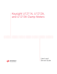
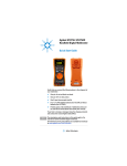
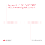
Making Measurements
Testing Diodes
2
Auto
Figure 2-22 Testing reverse bias diode
U1271A/U1272A User’s Guide
83
2
Making Measurements
Using Auto-diode for Diode Tests (U1272A only)
The auto- diode function will help you test both forward bias
and reverse bias directions simultaneously. You do not need
to change the measuring direction to identify the diode’s
status.
Table 2-2 Auto-diode voltage thresholds
NOTE
Forward voltage
Reverse voltage
Diode status
Primary display
Secondary display
OL or <0.3 V or >0.8 V
–OL or >–0.3 V or <–0.8 V
Within 0.3 V to 0.8 V
–OL
✔
OL
Within –0.3 V to –0.8 V
✔
Good
No Good
✘
The open condition will not be alerted as OL on both directions if the
auto-diode function is used.
1 Rotate the multimeter’s rotary switch to
your multimeter as shown in Figure 2- 21.
2 Press
Shift
Esc View
Auto
and set up
to activate the auto- diode function (Auto
).
The primary display shows the forward bias voltage value.
The reverse bias voltage value is shown in the secondary
display.
84
•
is shown briefly (along with a single beep) on the
secondary display if the diode is in a good condition.
•
is shown briefly (along with two beeps) if the
diode is out of the thresholds.
U1271A/U1272A User’s Guide
Making Measurements
Using Auto-diode for Diode Tests (U1272A only)
2
Figure 2-23 Auto-diode display - Good status
Figure 2-24 Auto-diode display - nGood status
U1271A/U1272A User’s Guide
85
2
Making Measurements
Measuring Capacitance
CAUTION
To avoid possible damage to the multimeter or to the equipment under
test, disconnect circuit power and discharge all high-voltage
capacitors before measuring capacitance. Use the DC voltage function
to confirm that the capacitor is fully discharged.
The multimeter measures capacitance by charging the
capacitor with a known current for a known period of time,
measuring the resulting voltage, and then calculating the
capacitance.
1 To measure capacitance, position the rotary switch to
and set up your multimeter as shown in Figure 2- 26.
2 Probe the test points and read the display.
is shown
on the bottom left of the display when the capacitor is
charging, and
is shown when the capacitor is
discharging.
Figure 2-25 Capacitance display
NOTE
86
To improve measurement accuracy of small value capacitors, press
with the test leads open to subtract the residual capacitance of the
multimeter and leads.
Null
Scale
U1271A/U1272A User’s Guide
Making Measurements
Measuring Capacitance
NOTE
2
For measuring capacitance values greater than 1000 μF, discharge the
capacitor first, then select a suitable range for measurement. This will
speed up the measurement time and also ensure that the correct
capacitance value is obtained.
Figure 2-26 Measuring capacitance
U1271A/U1272A User’s Guide
87
2
Making Measurements
Measuring Temperature
WA R N I N G
Do not connect the thermocouple to electrically live circuits. Doing
so will potentially cause fire or electric shock.
CAUTION
Do not bend the thermocouple leads at sharp angles. Repeated
bending over a period of time can break the leads.
The multimeter uses a type- K (default setting) temperature
probe for measuring temperature.
1 To measure temperature, position the rotary switch to
and press
once. Set up your multimeter as shown
in Figure 2- 29.
Shift
Esc View
2 Probe the test points and read the display. The primary
display normally shows temperature or the message
(open thermocouple). The open thermocouple message
may be due to a broken (open) probe or because no probe
is installed into the input jacks of the multimeter.
Figure 2-27 Temperature display
Range
Auto
Press
to change the temperature units between °C or
°F (you must first change the temperature unit to switch
between °C and °F or °F and °C). See “Changing the default
temperature unit” on page 90 for more information.
88
U1271A/U1272A User’s Guide
Making Measurements
Measuring Temperature
CAUTION
NOTE
2
Always set the temperature unit display per the official requirements
and in compliance with the National laws of your region.
Shorting the terminal to the
at the multimeter’s terminals.
terminal will display the temperature
Type K Thermocouple Probe
Figure 2-28 Measuring surface temperature
U1271A/U1272A User’s Guide
89
2
Making Measurements
Measuring Temperature
Changing the default thermocouple type (U1272A only)
You can change the thermocouple type (J or K) by accessing
the multimeter’s Setup.
1 Press
for more than 1 second to enter the
multimeter’s Setup mode.
Setup
Range
Auto
2 Press
until
display. Press
or
type.
Setup
Available options:
Dual
Exit
is shown on the secondary
to change the thermocouple
or
.
Hz % ms
Log
3 Press
to save the changes. Press and hold
the multimeter restarts.
Setup
until
Changing the default temperature unit
You can change the temperature unit (degree Celsius,
Celsius/Fahrenheit, Fahrenheit, or Fahrenheit/Celsius) by
accessing the multimeter’s Setup.
1 Press
for more than 1 second to enter the
multimeter’s Setup mode.
Setup
Shift
Esc View
2 Press
for more than 1 second until
shown on the secondary display. Press
or
change the temperature unit.
Setup
Dual
Exit
is
to
Available options:
•
- Temperature measured in °C.
•
Range
Auto
•
- During temperature measurements, press
to switch between °C and °F.
- Temperature measured in °F.
•
Range
Auto
- During temperature measurements, press
to switch between °F and °C.
Hz % ms
Log
3 Press
to save the changes. Press and hold
the multimeter restarts.
90
Setup
until
U1271A/U1272A User’s Guide
Making Measurements
Measuring Temperature
2
The bead- type thermocouple probe is suitable for measuring
temperatures from –40 °C to 204 °C (399 °F) in
PTFE- compatible environments. Above this temperature
range, the probe may emit toxic gas. Do not immerse this
thermocouple probe in any liquid. For best results, use a
thermocouple probe designed for each specific application —
an immersion probe for liquid or gel, and an air probe for
air measurement.
Observe the following measurement techniques:
• Clean the surface to be measured and ensure that the
probe is securely touching the surface. Remember to
disable the applied power.
• When measuring above ambient temperatures, move the
thermocouple along the surface until you get the highest
temperature reading.
• When measuring below ambient temperatures, move the
thermocouple along the surface until you get the lowest
temperature reading.
• Place the multimeter in the operating environment for at
least 1 hour as the multimeter is using a
non- compensation transfer adapter with miniature
thermal probe.
• For quick measurement, use the
compensation to view
the temperature variation of the thermocouple sensor. The
compensation assists you in measuring relative
temperature immediately.
U1271A/U1272A User’s Guide
91
2
Making Measurements
Measuring Temperature
Temperature measurement without ambient compensation
If you are working in a constantly varying environment,
where ambient temperatures are not constant, do the
following:
Dual
Exit
1 Press
to select
compensation. This allows a quick
measurement of the relative temperature.
2 Avoid contact between the thermocouple probe and the
surface to be measured.
Null
Scale
3 After a constant reading is obtained, press
to set
the reading as the relative reference temperature.
4 Touch the surface to be measured with the thermocouple
probe and read the display.
Figure 2-29 Temperature measurement without ambient compensation
92
U1271A/U1272A User’s Guide
Making Measurements
Measuring AC or DC Current
2
Measuring AC or DC Current
WA R N I N G
Never attempt an in-circuit current measurement where the
open-circuit potential to earth is greater than 1000 V. Doing so will
cause damage to the multimeter and possible electric shock or
personal injury.
CAUTION
To avoid possible damage to the multimeter or to the equipment under
test:
• Check the multimeter’s fuses before measuring current.
• Use the proper terminals, function, and range for your
measurement.
• Never place the probes across (in parallel with) any circuit or
component when the leads are plugged into the current terminals.
To measure current, you must open the circuit under test,
then place the multimeter in series with the circuit.
To measure AC or DC current, proceed as follows:
1 Turn off power to the circuit. Discharge all high- voltage
capacitors. Insert the black test lead into the
terminal. Insert the red test lead in an input appropriate
for the measurement range.
i If you are using the
to
.
terminal, set the rotary switch
ii If you are using the
terminal, set the rotary
switch to
for currents below 5000 μA (5 mA), or
for currents above 5000 μA.
NOTE
U1271A/U1272A User’s Guide
To avoid blowing the multimeter’s 440 mA fuse, use the
terminal
only if you are sure the current is less than 400 mA. See Figure 2-33 for
test lead connections and function selection. Refer to the “Input warning”
section for information on the alerts the multimeter uses when leads are
not used correctly for current measurements.
93
2
Making Measurements
Measuring AC or DC Current
Shift
Esc View
2 Press
to cycle between DC ( ), AC ( ), AC+DC
( ), or % scale (
or
) current measurements.
3 Open the circuit path to be tested. Probe the test points
and read the display.
Figure 2-30 DC current display
NOTE
Reversing the leads will produce a negative reading, but will not damage
the multimeter.
CAUTION
• For measuring AC current signals with a DC offset (U1272A only), refer
to the “Measuring AC and DC Signals (U1272A only)” on page 64.
• For measuring DC current from a mixed signal in DC measurement
mode, ensure that the Filter is enabled (Refer to “Enabling and
disabling the Filter” on page 131).
NOTE
• Press
to cycle through the available dual display combinations. See
Appendix B, “Dual Display Combinations Using the Dual Key,” starting
on page 179 to learn more.
Dual
Exit
• Press
to enable the frequency test mode for voltage
measurements. See “Frequency Test Mode” on page 101 to learn more.
Hz % ms
Log
94
U1271A/U1272A User’s Guide
Making Measurements
Measuring AC or DC Current
CAUTION
2
Placing the probes across (in parallel with) a powered circuit when a
lead is plugged into a current terminal can damage the circuit you are
testing and blow the multimeter's fuse. This happens because the
resistance through the multimeter's current terminals are very low,
resulting in a short circuit.
LOAD
DC
Figure 2-31 Measuring DC current
U1271A/U1272A User’s Guide
95
2
Making Measurements
Measuring AC or DC Current
AC
LOAD
Figure 2-32 Measuring AC current
96
U1271A/U1272A User’s Guide
Making Measurements
Measuring AC or DC Current
2
Figure 2-33 Current measurement setup
U1271A/U1272A User’s Guide
97
2
Making Measurements
Measuring AC or DC Current
% Scale of 4-20 mA or 0-20 mA
The 4- 20 mA current loop output from a transmitter is a
type of electrical signal that is used in a series circuit to
provide a robust measurement signal that is proportional to
the applied pressure, temperature, or flow in process
control. The signal is a current loop where 4 mA represents
the zero percent signal and 20 mA represents the 100
percent signal.
The % scale for 4- 20 mA or 0- 20 mA in this multimeter is
calculated using its corresponding DC mA measurement. The
multimeter will automatically optimize the best resolution for
the selected measurement. Two ranges are available for the
% scale as shown in Table 2- 3.
To display the current measurement in % scale:
1 Position your multimeter’s rotary switch position to
Set up your multimeter to measure DC current by
following the steps listed in the “Measuring AC or DC
Current” section.
.
Shift
Esc View
2 Press
until
(or
) is shown on the right
side of the display. Probe the test points and read the
display.
Figure 2-34 4-20 mA % Scale display
The analog bar graph displays the current measurement
value. (In the example above, 8 mA is represented as 25% in
the 4- 20 mA % scale.)
98
U1271A/U1272A User’s Guide
Making Measurements
Measuring AC or DC Current
2
Table 2-3 % Scale measurement range
% Scale of 4-20 mA or 0-20 mA
999.99%
DC mA measurement range
30 mA or 300 mA[1]
9999.9%
[1] Applies to both autoranging and manual range selection.
Changing the % scale range
You can change the % scale range (4- 20 mA or 0- 20 mA) by
accessing the multimeter’s Setup.
1 Press
for more than 1 second to enter the
multimeter’s Setup mode.
Setup
Range
Auto
2 Press
until
is shown on the secondary
display. Press
or
to change the current % scale
range. Available options:
mA,
mA, or
.
Setup
Hz % ms
Log
Dual
Exit
3 Press
to save the changes. Press and hold
the multimeter restarts.
Setup
until
Use the % scale with a pressure transmitter, a valve
positioner, or other output actuators to measure pressure,
temperature, flow, pH, or other process variables.
U1271A/U1272A User’s Guide
99
2
Making Measurements
Measuring AC or DC Current
Pressure transmitter
Figure 2-35 Measuring DC current using the 4-20 mA % scale
100
U1271A/U1272A User’s Guide
Making Measurements
Frequency Test Mode
2
Frequency Test Mode
WA R N I N G
Never measure the frequency where the voltage or current level
exceeds the specified range. Manually set the voltage or current
range if you want to measure frequencies below 20 Hz.
Measuring the frequency of a signal helps detect the
presence of harmonic currents in neutral conductors and
determines whether these neutral currents are the result of
unbalanced phases or non- linear loads.
Your multimeter allows simultaneous monitoring of realtime voltage or current with frequency, duty cycle, or pulse
width measurements. Figure 2- 36 highlights the primary
functions allowing frequency measurements in your
multimeter.
U1271A
U1272A
Figure 2-36 Functions allowing frequency measurement
U1271A/U1272A User’s Guide
101
2
Making Measurements
Frequency Test Mode
Measuring frequency
Frequency is the number of cycles a signal completes each
second. Frequency is defined as 1/Period. Period is defined
as the time between the middle threshold crossings of two
consecutive, like- polarity edges, as shown in Figure 2- 37.
The multimeter measures the frequency of a voltage or
current signal by counting the number of times the signal
crosses a threshold level within a specified period of time.
Rise Time
Fall Time
90%
50%
10%
+ Width
– Width
Period
Figure 2-37 Frequency, pulse width, and duty cycle measurements
Range
Auto
Pressing
controls the input range of the primary
function (voltage or ampere) and not the frequency range.
1 To measure frequency, rotate the switch to one of the
primary functions allowing frequency measurements
highlighted in Figure 2- 36.
NOTE
To obtain the best measuring results for frequency measurements, please
use the AC measuring path.
2 Press
102
Hz % ms
Log
. Probe the test points and read the display.
U1271A/U1272A User’s Guide
Making Measurements
Frequency Test Mode
2
Figure 2-38 Frequency display
The frequency of the input signal is shown in the primary
display. The voltage or ampere value of the signal is shown
in the secondary display. The bar graph does not indicate
frequency but indicates the voltage or ampere value of the
input signal.
Observe the following measurement techniques:
• If a reading shows as 0 Hz or is unstable, the input signal
may be below or near the trigger level. You can usually
correct these problems by manually selecting a lower
input range, which increases the sensitivity of the
multimeter.
• If a reading seems to be a multiple of what you expect,
the input signal may be distorted. Distortion can cause
multiple triggerings of the frequency counter. Selecting a
higher voltage range might solve this problem by
decreasing the sensitivity of the multimeter. In general,
the lowest frequency displayed is the correct one.
Hz % ms
Log
Press
to cycle through the frequency, pulse width, and
duty cycle measurements.
Dual
Exit
Press
for more than 1 second to exit the frequency
measurement function.
U1271A/U1272A User’s Guide
103
2
Making Measurements
Frequency Test Mode
Measuring pulse width
The pulse width function measures the amount of time a
signal is high or low, as shown in Figure 2- 37. It is the time
from the middle threshold of the rising edge to the middle
threshold of the next falling edge. The measured waveform
must be periodic; its pattern must repeat at equal time
intervals.
1 To measure pulse width, position the rotary switch to one
of the functions allowing frequency measurements shown
in Figure 2- 36.
Hz % ms
Log
2 Press
until the measurements are shown in the
millisecond (ms) unit. Probe the test points and read the
display.
Figure 2-39 Pulse width display
The pulse width of the input signal is shown in the primary
display. The voltage or ampere value of the signal is shown
in the secondary display. The bar graph does not indicate
duty cycle but indicates the voltage or ampere value of the
input signal.
The pulse width polarity is displayed to the left of the duty
cycle value.
indicates a positive pulse width and
indicates a negative pulse width. To change the polarity
being measured, press
.
Dual
Exit
Hz % ms
Log
Press
to cycle through the frequency, pulse width, and
duty cycle measurements.
104
U1271A/U1272A User’s Guide
Making Measurements
Frequency Test Mode
2
Dual
Exit
Press
for more than 1 second to exit the pulse width
measurement function.
Measuring duty cycle
The duty cycle (or duty factor) of a repetitive pulse train is
the ratio of the positive or negative pulse width to the
period expressed as a percentage, as shown in Figure 2- 37.
The duty- cycle function is optimized for measuring the on or
off time of logic and switching signals. Systems such as
electronic fuel injection systems and switching power
supplies are controlled by pulses of varying width, which
can be checked by measuring duty cycle.
1 To measure duty cycle, position the rotary switch on one
of the functions allowing frequency measurements shown
in Figure 2- 36.
Hz % ms
Log
2 Press
until the measurements are displayed as a
percentage (%). Probe the test points and read the
display.
Figure 2-40 Duty cycle display
The duty cycle percentage of the input signal is shown in the
primary display. The voltage or ampere value of the signal is
shown in the secondary display. The bar graph does not
indicate duty cycle but indicates the voltage or ampere value
of the input signal.
U1271A/U1272A User’s Guide
105
2
Making Measurements
Frequency Test Mode
The pulse polarity is displayed to the left of the duty cycle
value.
indicates a positive pulse and
indicates a
negative pulse. To change the polarity being measured,
press
.
Dual
Exit
Hz % ms
Log
Press
to cycle through the frequency, pulse width, and
duty cycle measurements.
Dual
Exit
Press
for more than 1 second to exit the duty cycle
measurement function.
106
U1271A/U1272A User’s Guide
U1271A/U1272A Handheld Digital Multimeter
User’s Guide
3
Multimeter Features
Making Relative Measurements (Null) 108
Making Scale Transfers (Scale) 110
Capturing Maximum and Minimum Values (MaxMin) 112
Capturing Peak Values (Peak) 114
Freezing the Display (TrigHold and AutoHold) 115
Recording Measurement Data (Data Logging) 116
Performing manual logs (HAnd) 117
Performing interval logs (AUto) 118
Performing event logs (triG) 120
Reviewing Previously Recorded Data (View) 122
The following sections describe the additional features
available in your multimeter.
3
Multimeter Features
Making Relative Measurements (Null)
When making null measurements, also called relative, each
reading is the difference between a stored (selected or
measured) null value and the input signal.
One possible application is to increase the accuracy of a
resistance measurement by nulling the test lead resistance.
Nulling the leads is also particularly important prior to
making capacitance measurements.
NOTE
Null can be set for both auto and manual range settings, but not in the
case of an overload.
Null
Scale
1 To activate the relative mode, press the
key. The
measurement value at the time that when Null ( ) is
enabled, is stored as the reference value.
Figure 3-1 Null display
Null
Scale
2 Press
again to view the stored reference value. The
display will return to normal after 3 seconds.
3 To disable the Null function, press
reference value is shown (step 2).
Null
Scale
while the stored
For any measurement function, you can directly measure and
store the null value by pressing
with the test leads
open (nulls the test lead capacitance), shorted (nulls the test
lead resistance), or across a desired null value circuit.
Null
Scale
108
U1271A/U1272A User’s Guide
Multimeter Features
Making Relative Measurements (Null)
NOTE
3
• In resistance measurement, the multimeter will read a non-zero value
even when the two test leads are in direct contact, because of the
resistance of these leads. Use the null function to zero-adjust the
display.
• For DC voltage measurements, the thermal effect will influence the
accuracy of the measurements. Short the test leads and press
when the displayed value is stable to zero-adjust the display.
Null
Scale
Press
Null
Scale
to enable the Null function.
Press
Null
Scale
Display returns
to normal after
3 seconds
Null
Scale
Press
again to
disable the Null function.
Figure 3-2 Null operation
U1271A/U1272A User’s Guide
109
3
Multimeter Features
Making Scale Transfers (Scale)
The Scale operation emulates a transducer by helping you to
convert the measured readings proportionally to the
specified ratio and unit display. Use Scale to transfer voltage
readings to proportional readings when using clamp- on
current probes or high voltage probes. The available scale
conversions are shown in the table below.
Table 3-1 Available scale conversions
Multiplier[1]
Unit
Related units
1000 V/V
1000.0
V
V, kV
1 A/mV
1000 A/V
1000.0
A
A, kA
1 A/10 mV
100A/V
100.0
A
A, kA
1 A/100 mV
10 A/V
10.0
A
mA, A, kA
Scale conversion
1 kV/V
[2]
[1] The transfer formula used is: Display = Multiplier × Measurement
[2] This value and unit can be adjusted from the multimeter’s Setup. See “Changing
the user scale conversion value and unit” on page 149 for more information.
Null
Scale
1 Press and hold
the Scale operation.
for more than 1 second to enable
2 The most recently saved (default: 1 kV/V, ×1000.0) ratio
and unit will be shown on the primary and secondary
displays. Press
while the
symbol is flashing
to cycle through the available ratio and unit displays.
Null
Scale
Hz % ms
Log
3 Press
while the
symbol is flashing to save
the selected ratio and unit and start the conversion. The
selected ratio and unit will be used as the default ratio
and unit the next time Scale is enabled.
4 Or, while the
symbol is flashing, if no activity is
detected after 3 seconds, the conversion will begin (with
the specified ratio and unit shown on the primary
display).
Null
Scale
5 Press and hold
the Scale operation.
110
for more than 1 second to cancel
U1271A/U1272A User’s Guide
Multimeter Features
Making Scale Transfers (Scale)
NOTE
The
Hz % ms
Log
3
is disabled during Scale operations. Press
to enable the frequency
test mode for voltage and current measurements during Scale operations.
Press
Null
Scale
Dual
Exit
Press
.
Dual
Exit
.
Hz % ms
Log
Press
or after 3
seconds of
inactivity.
Figure 3-3 Scale operation
U1271A/U1272A User’s Guide
111
3
Multimeter Features
Capturing Maximum and Minimum Values (MaxMin)
The MaxMin operation stores the maximum, minimum, and
average input values during a series of measurements.
When the input goes below the recorded minimum value or
above the recorded maximum value, the multimeter beeps
and records the new value. The elapsed time since the
recording session was started is stored and shown on the
display at the same time. The multimeter also calculates an
average of all readings taken since the MaxMin mode was
activated.
From the multimeter’s display, you can view the following
statistical data for any set of readings:
• Max: highest reading since the MaxMin function was
enabled
• Min: lowest reading since the MaxMin function was
enabled
• Avg: average or mean of all readings since the MaxMin
function was enabled
• MaxMinAvg: present reading (actual input signal value)
NOTE
This function is applicable to all measurements except for continuity and
diode tests.
1 Press
MaxMin
Peak
to enable the MaxMin operation.
MaxMin
Peak
2 Press
again to cycle through the Max, Min, Avg, or
present (MaxMinAvg) input values.
112
U1271A/U1272A User’s Guide
Multimeter Features
Capturing Maximum and Minimum Values (MaxMin)
3
Figure 3-4 MaxMin display
3 The elapsed time is shown on the secondary display.
Press
to restart the recording session.
Dual
Exit
NOTE
• Changing the range manually will also restart the recording session.
• If an overload is recorded, the averanging function will be stopped.
is shown in place of the average value.
• The APO (auto power-off) function is disabled when MaxMin is
enabled.
• The maximum recording time is 99.59.59 (hh.mm.ss).
recording exceeds the maximum time.
is shown if the
Dual
Exit
4 Press
for more than 1 second to disable the MaxMin
function.
This mode is useful for capturing intermittent readings,
recording minimum and maximum readings unattended, or
recording readings while equipment operation keeps you
from observing the multimeter display.
The true average value displayed is the arithmetic mean of
all readings taken since the start of recording. The average
reading is useful for smoothing out unstable inputs,
calculating power consumption, or estimating the percentage
of time a circuit is active.
U1271A/U1272A User’s Guide
113
3
Multimeter Features
Capturing Peak Values (Peak)
This function allows the measurement of peak voltage for
analysis of such components as power distribution
transformers and power factor correction capacitors.
1 To activate the peak mode, press the
key for more
than 1 second.
2 Press
again to display the maximum (HoldMax) or
minimum (HoldMin) peak values along with their
respective time stamps.
MaxMin
Peak
MaxMin
Peak
Figure 3-5 Peak display
Range
Auto
3 If
(overload) is shown, press the
key to change
the measurement range. This action will also restart the
recording session.
4 Press
to restart the recording session without
changing the measurement range.
5 Press
or
for more than 1 second to disable the
Peak function.
When the peak value of the input signal goes below the
recorded minimum value or above the recorded maximum
value, the multimeter beeps and records the new value.
At the same time, the elapsed time since the peak recording
session was started is stored as the recorded value’s time
stamp.
Dual
Exit
Dual
Exit
NOTE
114
MaxMin
Peak
The APO (auto power-off) function is disabled when Peak is enabled.
U1271A/U1272A User’s Guide
Multimeter Features
Freezing the Display (TrigHold and AutoHold)
3
Freezing the Display (TrigHold and AutoHold)
TrigHold operation
To freeze the display for any function, press the
Trig
Auto Hold
key.
Trig
Auto Hold
If
is pressed while a MaxMin, Peak, or Data Logging
recording session is in progress, the display freezes but the
data acquisition continues in the background. Pressing
again updates the display to reflect data that was acquired
during the hold.
Trig
Auto Hold
AutoHold operation
Trig
Auto Hold
Pressing the
for more that 1 second activates the
AutoHold if the multimeter is not in the MaxMin, Peak, or
Data Logging recording modes.
AutoHold operation monitors the input signal and updates
the display and, if enabled, emits a beep, whenever a new
stable measurement is detected. A stable measurement is
one that does not vary more than a selected adjustable
(AutoHold threshold) variation count for at least one second
(default 500 counts). Open lead conditions are not included
in the update.
Changing the default AutoHold threshold count
1 Press
for more than 1 second to enter the
multimeter’s Setup mode.
Setup
2
press
should be shown on the secondary display. (If not,
or
until it is shown.)
Range
Auto
MaxMin
Peak
Dual
Exit
3 Press
display.
or
Hz % ms
Log
Setup
to edit the value shown on the primary
4 Press
to save the changes. Press and hold
the multimeter restarts.
NOTE
U1271A/U1272A User’s Guide
Setup
until
If the reading value is unable to reach a stable state (when exceeding the
preset variation), the reading value will not be updated.
115
3
Multimeter Features
Recording Measurement Data (Data Logging)
The Data Logging function provides you the convenience of
recording test data for future review or analysis. Since data
is stored in the nonvolatile memory, the data remains saved
even when the multimeter is turned OFF or if the battery is
replaced.
The Data Logging feature collects measurement information
over a user- specified duration. There are three data logging
options that can be used to capture measurement data:
manual (
), interval (
), or event (
).
• A manual log stores an instance of the measured signal
each time
is pressed. See page 117.
Hz % ms
Log
• An interval log stores a record of the measured signal at
a user- specified interval. See page 118.
• An event log stores a record of the measured signal each
time a trigger condition is satisfied. See page 120.
Table 3-2 Data logging maximum capacity
Maximum capacity for saving
Data logging option
U1271A
U1272A
Manual (
)
100
100
Interval (
)
200
10000
Event (
)
Shares the same memory with Interval logging
Before starting a recording session, set up the multimeter
for the measurements to be recorded.
116
U1271A/U1272A User’s Guide
Multimeter Features
Recording Measurement Data (Data Logging)
3
Select the data logging option
1 Press
for more than 1 second to enter the
multimeter’s Setup mode.
Setup
Range
Auto
2 Press
until
display. Press
or
option.
Setup
Available options:
Dual
Exit
,
Hz % ms
Log
is shown on the secondary
to change the data logging
, or
.
3 Press
to save the changes. Press and hold
the multimeter restarts.
Setup
until
Performing manual logs (HAnd)
Ensure that
is selected as the data logging option in
the multimeter’s Setup.
Hz % ms
Log
1 Press
for more than 1 second to store the present
input signal value.
and the log entry number are displayed at the top
of the display. The display will return to normal after a
short while (around 1 s).
Figure 3-6 Manual log display
2 Repeat step 1 again to save the next input signal value.
U1271A/U1272A User’s Guide
117
3
Multimeter Features
Recording Measurement Data (Data Logging)
The maximum number of readings that can be stored for the
manual log is 100 entries. When all entries are occupied,
will be shown when
is pressed.
Hz % ms
Log
See the “Reviewing Previously Recorded Data (View)” section
later in this manual to review or erase the recorded entries.
Performing interval logs (AUto)
Ensure that
is selected as the data logging option in
the multimeter’s Setup.
Set the recording interval duration
1 Press
for more than 1 second to enter the
multimeter’s Setup mode.
Setup
Range
Auto
2 Press
until
is shown on the secondary
display. Press
or
to change the duration or a
recording interval from 1 to 99999 seconds (default 1
second).
Setup
Hz % ms
Log
Dual
Exit
3 Press
to save the changes. Press and hold
the multimeter restarts.
Setup
until
The duration set in the steps above will determine how long
each recording interval takes. The input signal value at the
end of each interval will be recorded and saved into the
multimeter’s memory.
Start the interval log mode
1 Press
mode.
Hz % ms
Log
for more than 1 second to start interval log
and the log entry number are displayed at the top
of the display. Subsequent readings are automatically
recorded into the multimeter’s memory at the interval
specified in the Setup mode.
118
U1271A/U1272A User’s Guide
Multimeter Features
Recording Measurement Data (Data Logging)
3
Figure 3-7 Interval log display
Hz % ms
Log
2 Press
log mode.
for more than 1 second to exit the interval
The maximum number of readings that can be stored for the
interval log is 10000 entries for the U1272A and 200 entries
for the U1271A. When all entries are occupied,
will
be shown when
is pressed.
Hz % ms
Log
The interval and event log share the same memory buffer
(total combined: 10000 entries for U1272A and 200 entries
for U1271A). Increased usage of the interval log entries will
lead to the decrease of the maximum entries for the event
log, and vice versa.
See the “Reviewing Previously Recorded Data (View)” section
later in this manual to review or erase the recorded entries.
NOTE
U1271A/U1272A User’s Guide
When the interval log recording session is running, all other keypad
operations are disabled; except for
, which, when pressed for more
than 1 second, will stop and exit the recording session. Furthermore, APO
(auto power-off) is disabled during the recording session.
Hz % ms
Log
119
3
Multimeter Features
Recording Measurement Data (Data Logging)
Performing event logs (triG)
Ensure that
is selected as the data logging option in
the multimeter’s Setup.
Event logs are used only with the following modes:
• TrigHold and AutoHold (page 115)
• MaxMin recording (page 112)
• Peak recording (page 114)
Event records are triggered by the measured signal satisfying
a trigger condition set by the measurement function used in
the following modes:
Table 3-3 Event log trigger conditions
Modes
Trigger condition
The input signal value is recorded:
Trig
Auto Hold
TrigHold
Each time
is pressed.
AutoHold
When the input signal varies more than the variation
count.
MaxMin
When a new maximum (or minimum) value is recorded.
The average and present readings are not recorded in the
Event log.
Peak
When a new peak (maximum or minimum) value is
recorded.
Start the event log mode
1 Select one of the four modes stated in Table 3- 3.
2 Press
mode.
Hz % ms
Log
for more than 1 second to start event log
and the log entry number are displayed at the top
of the display. Subsequent readings are automatically
recorded into the multimeter’s memory every time the
trigger condition specified in Table 3- 3 is satisfied.
120
U1271A/U1272A User’s Guide
Multimeter Features
Recording Measurement Data (Data Logging)
3
Figure 3-8 Event log display
3 Press
mode.
Hz % ms
Log
for more than 1 second to exit the event log
The maximum number of readings that can be stored for the
event log is 10000 entries for the U1272A and 200 entries
for the U1271A. When all entries are occupied,
will
be shown when
is pressed.
Hz % ms
Log
The event and interval log share the same memory buffer
(total combined: 10000 entries for U1272A and 200 entries
for U1271A). Increased usage of the event log entries will
lead to the decrease of the maximum entries for the interval
log, and vice versa.
See the “Reviewing Previously Recorded Data (View)” section
later in this manual to review or erase the recorded entries.
NOTE
U1271A/U1272A User’s Guide
APO (auto power-off) is disabled during the recording session.
121
3
Multimeter Features
Reviewing Previously Recorded Data (View)
Viewing data stored in the multimeter’s memory is
performed through the
key.
Shift
Esc View
Shift
Esc View
1 Press
for more than 1 second to enter the
multimeter’s View mode. Press
again to cycle
through the manual (H), interval (A), or event (E)
previously stored records.
Shift
Esc View
Figure 3-9 View display
If nothing has been recorded,
be displayed instead.
,
, or
will
Figure 3-10 Empty view display
122
U1271A/U1272A User’s Guide
Multimeter Features
Reviewing Previously Recorded Data (View)
3
2 Select the desired recording category to view its entries.
i Press
MaxMin
Peak
to jump to the first stored entry.
Range
Auto
ii Press
to jump to the last stored entry.
Dual
Exit
iii Press
to view the next stored entry. The index
number increases by one.
iv Press
to view the previous stored entry. The index
number decreases by one.
Setup
Hz % ms
Log
v Press
for more than 1 second to clear all entries
for the selected log type.
3 Press
mode.
U1271A/U1272A User’s Guide
Shift
Esc View
for more than 1 second to exit the View
123
3
Multimeter Features
Reviewing Previously Recorded Data (View)
THIS PAGE HAS BEEN INTENTIONALLY LEFT BLANK.
124
U1271A/U1272A User’s Guide
U1271A/U1272A Handheld Digital Multimeter
User’s Guide
4
Multimeter Setup Options
Using the Setup Menu 126
Editing numerical values 127
Setup Menu Summary 128
Setup Menu Items 130
Changing the beep frequency 130
Enabling and disabling the Filter 131
Changing the variation count 133
Changing the recording option 134
Changing the sample interval duration 135
Changing the decibel display (U1272A only) 136
Setting a custom dBm reference impedance (U1272A only) 137
Changing the auto power-off and backlight timeouts 138
Enabling and disabling the overvoltage alert 140
Changing the % scale range 141
Changing the thermocouple type (U1272A only) 142
Changing the minimum measurable frequency 143
Changing the baud rate 144
Changing the data bits 145
Changing the parity check 146
Enabling and disabling the backlight alert 147
Enabling smooth mode 148
Changing the user scale conversion value and unit 149
Resetting the multimeter’s setup options 150
Changing the temperature unit 151
The following sections describe how to change the preset
features of your multimeter.
4
Multimeter Setup Options
Using the Setup Menu
The multimeter’s setup menu allows you to change a number
of nonvolatile preset features. Modifying these settings
affects the general operation of your multimeter across
several functions. Select a setting to edit to perform one of
the following:
• Switch between two values, such as on or off.
• Cycle through multiple values from a predefined list.
• Decrease or increase a numerical value within a fixed
range.
To contents of the setup menu are summarized in Table 4- 2
on page 128.
Table 4-1 Setup menu key functions
Legend
Description
Press
for more than 1 second to access the
setup menu.
Setup
Press and hold
until the multimeter restarts to
exit the setup menu.
Setup
Setup
Range
Auto
MaxMin
Peak
Press
items.
MaxMin
Peak
126
Range
Auto
to step through the menu
Press
or
at each menu item to change the
preset settings. The menu item (in the secondary
display) will flash to indicate that you can now
change the values shown in the primary display.
Dual
Exit
Dual
Exit
or
Setup
Setup
Press
or
again to switch between two
values, to cycle through multiple values from a list,
or to decrease or increase a numerical value.
Dual
Exit
Setup
Hz % ms
Log
While the menu item is flashing, press
save your changes.
Hz % ms
Log
to
Shift
Esc View
While the menu item is flashing, press
discard your changes.
Shift
Esc View
to
U1271A/U1272A User’s Guide
Multimeter Setup Options
Using the Setup Menu
4
Editing numerical values
When editing numerical values, use the
position the cursor on a numerical digit.
• Press
• Press
MaxMin
Peak
MaxMin
Peak
and
Range
Auto
to
to move the cursor to the left, and
Range
Auto
to move the cursor to the right.
When the cursor is positioned over a digit, use the
keys to change the numerical digit.
Dual
Exit
and
Setup
• Press
• Press
Dual
Exit
Setup
to increment the digit, and
to decrement the digit.
When you have completed your changes, save the new
numerical value by pressing
. (Or alternatively, if you
wish to discard the changes you made, press
.)
Hz % ms
Log
Shift
Esc View
U1271A/U1272A User’s Guide
127
4
Multimeter Setup Options
Setup Menu Summary
Setup Menu Summary
The Setup menu items are summarized in the table below.
Click the respective “Learn more” pages for more
information on each menu item.
Table 4-2 Setup menu item descriptions
Legend
Available settings
Hz,
Hz,
Hz, or
Hz,
,
, or
to
counts
,
, or
to
dBm,
s
dBV, or
Ω
to
to
minutes or
to
s or
to
V or
mA,
mA, or
or
128
Description
Learn more on:
Set the multimeter’s beep frequency from 3200 Hz to
4267 Hz or off. Default is 3491 Hz.
page 130
for DC, AC, and AC+DC(U1272A only)
Enable the
voltage and current measuring paths. Default is dC.
page 59 and
page 131
Set the multimeter’s AutoHold threshold count from 50 to
9999 counts. Default is 500 counts.
page 115 and
page 133
Set the multimeter’s data logging option (manual log,
interval log, or event log). Default is manual log (HAnd).
page 116 and
page 134
Set the logging duration for interval logs from 1 to 99999
seconds (1 day, 3 hours, 46 minutes, 39 seconds). Default
is 1 second.
page 118 and
page 135
U1272A only — Set the multimeter to display voltage as a
dB value (dBm/dBV) or off. Default is dBm.
page 66 and
page 136
U1272A only — Set the dBm reference impedance value
from 1 Ω to 9999 Ω. Default is 50 Ω.
page 66 and
page 137
Set the auto power-off timeout period from 1 to 99 minutes
(1 hour, 39 minutes) or off. Default is 15 minutes.
page 26 and
page 138
Set the LCD backlight timeout period from 1 to 99 seconds
(1 minute, 39 seconds) or off. Default is 15 seconds.
page 27 and
Set the multimeter’s voltage alert value from 0.1 V to
1010 V or off. Default is off.
page 28 and
page 140
Set the multimeter’s % scale selection (0-20 mA/4-20 mA)
or off. Default is 4-20 mA.
page 98 and
page 141
U1272A only — Set the multimeter’s thermocouple type
(type J or type K). Default is type K.
page 88 and
page 142
page 138
U1271A/U1272A User’s Guide
Multimeter Setup Options
Setup Menu Summary
4
Table 4-2 Setup menu item descriptions (continued)
Legend
Available settings
page 101 and
page 143
or
Set the baud rate for remote communication with a PC
(9600, or 19200). Default is 9600.
page 30 and
page 144
or
Set the data bit length for remote communication with a
PC (7-bit or 8-bit). Default is 8-bit.
page 30 and
page 145
Set the parity bit for remote communication with a PC
(none, even, or odd). Default is none.
page 30 and
page 146
Set the multimeter to flash the backlight during alerts.
Default is on.
page 74 and
page 147
Set the primary display’s settling value from (0001.d) to
(9999.d) or (0001.E) to (9999.E). Default is disabled
(0009.d).
page 32 and
page 148
Set the scale conversion value from (0000.1) to (1000.0).
The scale conversion unit can be set to V/V, A/V, or 000
(no unit)/V. Default is (1000.0) V/V.
page 110 and
page 149
Hz
, or
or
to
to
or
(
to
) V/V,
A/V, or 000 (no unit)/V
Reset the multimeter to its factory default settings.
,
,
Learn more on:
Set the minimum measurement frequency (0.5 Hz or
10 Hz). Default is 0.5 Hz.
Hz or
,
Description
, or
U1271A/U1272A User’s Guide
Set the multimeter’s temperature unit (Celsius,
Celsius/Fahrenheit, Fahrenheit, Fahrenheit/Celsius).
Default is °C (Celsius).
page 150
page 88 and
page 151
129
4
Multimeter Setup Options
Setup Menu Items
Setup Menu Items
Changing the beep frequency
The multimeter’s beeper alerts users to the presence of
circuit continuities, operator errors such as incorrect lead
connections for the selected function, and newly sensed
values for MaxMin and Peak recordings.
Parameter
Range
Default setting
bEEP
3200 Hz, 3491 Hz, 3840 Hz, 4267 Hz, or
Off
3491 Hz
To change the beep frequency:
1 Press
for more than 1 second to enter the
multimeter’s setup menu.
Setup
MaxMin
Peak
2 Press
or
secondary display.
Range
Auto
until
is shown on the
Figure 4-1 bEEP display
Dual
Exit
3 Press
or
to change the beep frequency. Select
to disable the beeper feature.
Hz % ms
Log
Setup
4 Press
to save your changes or press
discard your changes.
130
Shift
Esc View
to
U1271A/U1272A User’s Guide
Multimeter Setup Options
Setup Menu Items
4
5 Press and hold
until the multimeter restarts to return
to normal operation.
Setup
Enabling and disabling the Filter
There are two Filter (
multimeter:
) options within the design of the
• In AC/AC+DC measurement mode, the Filter works as a
low pass filter and attenuates signals with frequencies of
more than 1 kHz
• In DC measurement mode, the Filter will block AC signals
Only one of the two filters can be in the signal path at any
point in time. The possible scenarios are:
• Only the AC Low Pass Filter is enabled
• Only the DC Filter is enabled
• No Filter in the signal path
The
icon appears when either of the filter circuits are
enabled. When either LPF is enabled, the measurement
speed (response time) will be impacted.
NOTE
U1271A/U1272A User’s Guide
The DC Filter cannot be used when the dual display mode is enabled
where AC and DC voltages are measured.
131
4
Multimeter Setup Options
Setup Menu Items
Table 4-3 Filter (LPF) options
Filter setting
Measurement
DC[1]
DCAC
OFF
OFF
Low Pass Filter
OFF
DC
Filter (blocks AC)
Filter (blocks AC)
OFF
Dual display
OFF
Low Pass Filter
OFF
[2]
AC/AC+DC
[1] The Filter (DC) will be set to ON as the factory default. You may change it to an
alternate setting, and the multimeter will remember the chosen setting for consecutive uses.
[2] The AC+DC measurement mode is only valid for the U1272A only.
You may enable the Filter for DC coupling of voltage and/or
current measurements. The
icon will be shown during
the measurement.
Table 4-4 Firmware version 2.00 or older
Parameter
Range
Default setting
FiLtEr
on or oFF
oFF
Table 4-5 Firmware version 2.04 or newer
CAUTION
132
Parameter
Range
Default setting
FiLtEr
dC, dCAC, or oFF
dC
To avoid possible electric shock or personal injury, enable the Filter(LPF) to
verify the presence of hazardous DC voltages. Displayed DC voltage values
can be influenced by high frequency AC components and must be filtered
to assure an accurate reading.
U1271A/U1272A User’s Guide
Multimeter Setup Options
Setup Menu Items
4
To enable/disable the Filter:
1 Press
for more than 1 second to enter the
multimeter’s setup menu.
Setup
MaxMin
Peak
2 Press
or
secondary display.
Range
Auto
until
is shown on the
Figure 4-2 FiLtEr display
3 Press
Select
Dual
Exit
or
to enable the filters (
to disable the filters.
Setup
Hz % ms
Log
4 Press
to save your changes or press
discard your changes.
is selected).
Shift
Esc View
to
5 Press and hold
until the multimeter restarts to return
to normal operation.
Setup
Changing the variation count
This setting is used with the multimeter’s AutoHold feature
(see page 115). When the variation of the measured value
exceeds the value of the variation count, the AutoHold
feature will be ready to trigger.
U1271A/U1272A User’s Guide
Parameter
Range
Default setting
AHoLd
(50 to 9999) counts
500 counts
133
4
Multimeter Setup Options
Setup Menu Items
To change the variation count:
1 Press
for more than 1 second to enter the
multimeter’s setup menu.
Setup
MaxMin
Peak
2 Press
or
secondary display.
Range
Auto
until
is shown on the
Figure 4-3 AHOLd display
3 Press
Dual
Exit
or
Setup
to set the variation count.
Hz % ms
Log
4 Press
to save your changes or press
discard your changes.
Shift
Esc View
to
5 Press and hold
until the multimeter restarts to return
to normal operation.
Setup
Changing the recording option
This setting is used with the multimeter’s Data Logging
feature (see page 116). There are three available recording
options for the multimeter’s Data Logging feature.
134
Parameter
Range
Default setting
d-LoG
HAnd, AUto, or TriG
HAnd
U1271A/U1272A User’s Guide
Multimeter Setup Options
Setup Menu Items
4
To change the recording option:
1 Press
for more than 1 second to enter the
multimeter’s setup menu.
Setup
MaxMin
Peak
2 Press
or
secondary display.
Range
Auto
until
is shown on the
Figure 4-4 d-LoG display
3 Press
Dual
Exit
or
Setup
to set the recording option.
Hz % ms
Log
4 Press
to save your changes or press
discard your changes.
Shift
Esc View
to
5 Press and hold
until the multimeter restarts to return
to normal operation.
Setup
Changing the sample interval duration
This setting is used with the multimeter’s Interval Data
Logging feature (see page 118). The multimeter will record a
measurement value at the beginning of every sample
interval.
U1271A/U1272A User’s Guide
Parameter
Range
Default setting
L-tiME
(1 to 99999) s
1s
135
4
Multimeter Setup Options
Setup Menu Items
To change the sample interval duration:
1 Press
for more than 1 second to enter the
multimeter’s setup menu.
Setup
MaxMin
Peak
2 Press
or
secondary display.
Range
Auto
until
is shown on the
Figure 4-5 L-tiME display
3 Press
Dual
Exit
or
Setup
to set the sample interval duration.
Hz % ms
Log
4 Press
to save your changes or press
discard your changes.
Shift
Esc View
to
5 Press and hold
until the multimeter restarts to return
to normal operation.
Setup
Changing the decibel display (U1272A only)
This setting is used with dB measurements (see page 66).
You can enable the multimeter to display voltage as a dB
value, either relative to 1 milliwatt (dBm) or a reference
voltage of 1 volt (dBV).
136
Parameter
Range
Default setting
dCibEL
On dBm, On dBV, or Off
On dBm
U1271A/U1272A User’s Guide
Multimeter Setup Options
Setup Menu Items
4
To change the decibel display:
1 Press
for more than 1 second to enter the
multimeter’s setup menu.
Setup
MaxMin
Peak
2 Press
or
secondary display.
Range
Auto
until
is shown on the
Figure 4-6 dCibEL display
Dual
Exit
3 Press
or
to change the decibel display. Select
to disable dB measurements.
Setup
Hz % ms
Log
4 Press
to save your changes or press
discard your changes.
Shift
Esc View
to
5 Press and hold
until the multimeter restarts to return
to normal operation.
Setup
Setting a custom dBm reference impedance (U1272A only)
This setting is used with dB measurements (see page 66).
The dBm function is logarithmic, and is based on a
calculation of power delivered to a reference impedance
(resistance), relative to 1 mW.
U1271A/U1272A User’s Guide
Parameter
Range
Default setting
dbrEF
(1 to 9999) Ω
50 Ω
137
4
Multimeter Setup Options
Setup Menu Items
To change the dBm reference impedance value:
1 Press
for more than 1 second to enter the
multimeter’s setup menu.
Setup
MaxMin
Peak
2 Press
or
secondary display.
Range
Auto
until
is shown on the
Figure 4-7 dbrEF display
3 Press
value.
Dual
Exit
or
Setup
to set the dBm reference impedance
Hz % ms
Log
4 Press
to save your changes or press
discard your changes.
Shift
Esc View
to
5 Press and hold
until the multimeter restarts to return
to normal operation.
Setup
Changing the auto power-off and backlight timeouts
The multimeter’s automatic power- off (see page 26) and
backlight (see page page 27) features use timers to
determine when to turn off the backlight and when to
automatically turn the multimeter off.
138
Parameter
Range
Default setting
APo
(1 to 99) minutes or Off
15 minutes
bLit
(1 to 99) s or Off
15 s
U1271A/U1272A User’s Guide
Multimeter Setup Options
Setup Menu Items
4
To change the auto power- off and backlight timeout periods:
1 Press
for more than 1 second to enter the
multimeter’s setup menu.
Setup
Range
Auto
MaxMin
Peak
2 Press
or
secondary display.
until
or
is shown on the
Figure 4-8 APo display
Figure 4-9 bLit display
Dual
Exit
3 Press
or
to change the timeout period. Select
to disable the timeout feature.
Setup
Hz % ms
Log
4 Press
to save your changes or press
discard your changes.
Shift
Esc View
to
5 Press and hold
until the multimeter restarts to return
to normal operation.
Setup
U1271A/U1272A User’s Guide
139
4
Multimeter Setup Options
Setup Menu Items
Enabling and disabling the overvoltage alert
This setting is used with the multimeter’s overvoltage alert
(see page 28). The multimeter’s will start beeping
periodically once the measured voltage exceeds the value set,
regardless of polarity.
Parameter
Range
Default setting
ALErt
(0.1 to 1010) V or Off
Off
To enable the overvoltage’s alert:
1 Press
for more than 1 second to enter the
multimeter’s setup menu.
Setup
MaxMin
Peak
2 Press
or
secondary display.
Range
Auto
until
is shown on the
Figure 4-10 ALErt display
Dual
Exit
3 Press
or
to set the overvoltage alert level. Select
to disable the overvoltage alert feature.
Setup
Hz % ms
Log
4 Press
to save your changes or press
discard your changes.
Shift
Esc View
to
5 Press and hold
until the multimeter restarts to return
to normal operation.
Setup
140
U1271A/U1272A User’s Guide
Multimeter Setup Options
Setup Menu Items
4
Changing the % scale range
This setting is used with % scale current measurements (see
page 98). The multimeter converts DC current measurements
to a percentage scale readout of 0% to 100% based on the
selected range in this menu. For example, a 25% readout
represents a DC current of 8 mA on the 4- 20 mA % scale, or
a DC current of 5 mA on the 0- 20 mA % scale.
Parameter
Range
Default setting
PErCEn
4-20 mA, 0-20 mA, or Off
4-20 mA
To change the % scale range:
1 Press
for more than 1 second to enter the
multimeter’s setup menu.
Setup
MaxMin
Peak
2 Press
or
secondary display.
Range
Auto
until
is shown on the
Figure 4-11 PErCEn display
Dual
Exit
3 Press
or
to change the % scale range. Select
to disable the % scale readout.
Setup
Hz % ms
Log
4 Press
to save your changes or press
discard your changes.
Shift
Esc View
to
5 Press and hold
until the multimeter restarts to return
to normal operation.
Setup
U1271A/U1272A User’s Guide
141
4
Multimeter Setup Options
Setup Menu Items
Changing the thermocouple type (U1272A only)
This setting is used with temperature measurements (see
page 88). Select a thermocouple type that matches the
thermocouple sensor you are using for temperature
measurements.
Parameter
Range
Default setting
CoUPLE
tYPE K or tYPE J
tYPE K
To change the thermocouple type:
1 Press
for more than 1 second to enter the
multimeter’s setup menu.
Setup
MaxMin
Peak
2 Press
or
secondary display.
Range
Auto
until
is shown on the
Figure 4-12 CoUPLE display
3 Press
Dual
Exit
or
Setup
to change the thermocouple type.
Hz % ms
Log
4 Press
to save your changes or press
discard your changes.
Shift
Esc View
to
5 Press and hold
until the multimeter restarts to return
to normal operation.
Setup
142
U1271A/U1272A User’s Guide
Multimeter Setup Options
Setup Menu Items
4
Changing the minimum measurable frequency
This setting is used with frequency tests (see page 101).
Changing the minimum measurable frequency will influence
the measurement rates for frequency, duty cycle, and pulse
width measurements. The typical measurement rate as
defined in the specification is based on a minimum
measurable frequency of 10 Hz.
Parameter
Range
Default setting
FrEq
0.5 Hz or 10 Hz
0.5 Hz
To change the minimum measurable frequency:
1 Press
for more than 1 second to enter the
multimeter’s setup menu.
Setup
MaxMin
Peak
2 Press
or
secondary display.
Range
Auto
until
is shown on the
Figure 4-13 FrEq display
3 Press
Dual
Exit
or
Setup
to change the frequency value.
Hz % ms
Log
4 Press
to save your changes or press
discard your changes.
Shift
Esc View
to
5 Press and hold
until the multimeter restarts to return
to normal operation.
Setup
U1271A/U1272A User’s Guide
143
4
Multimeter Setup Options
Setup Menu Items
Changing the baud rate
This setting changes the baud rate for remote
communications with a PC.
Parameter
Range
Default setting
bAUd
(9600 or 19200) bits/second
9600
bits/second
To change the baud rate:
1 Press
for more than 1 second to enter the
multimeter’s setup menu.
Setup
MaxMin
Peak
2 Press
or
secondary display.
Range
Auto
until
is shown on the
Figure 4-14 bAUd display
3 Press
Dual
Exit
or
Setup
to change the baud rate.
Hz % ms
Log
4 Press
to save your changes or press
discard your changes.
Shift
Esc View
to
5 Press and hold
until the multimeter restarts to return
to normal operation.
Setup
144
U1271A/U1272A User’s Guide
Multimeter Setup Options
Setup Menu Items
4
Changing the data bits
This setting changes the number of data bits (data width)
for remote communications with a PC. The number of stop
bit is always 1, and this cannot be changed.
Parameter
Range
Default setting
dAtAb
8-bit or 7-bit
8-bit
To change the data bit:
1 Press
for more than 1 second to enter the
multimeter’s setup menu.
Setup
MaxMin
Peak
2 Press
or
secondary display.
Range
Auto
until
is shown on the
Figure 4-15 dAtAb display
3 Press
Dual
Exit
or
Setup
to change the data bit.
Hz % ms
Log
4 Press
to save your changes or press
discard your changes.
Shift
Esc View
to
5 Press and hold
until the multimeter restarts to return
to normal operation.
Setup
U1271A/U1272A User’s Guide
145
4
Multimeter Setup Options
Setup Menu Items
Changing the parity check
This setting changes the parity check for remote
communications with a PC.
Parameter
Range
Default setting
PAritY
nonE, En, or odd
nonE
To change the data bit:
1 Press
for more than 1 second to enter the
multimeter’s setup menu.
Setup
MaxMin
Peak
2 Press
or
secondary display.
Range
Auto
until
is shown on the
Figure 4-16 PAritY display
3 Press
Dual
Exit
or
Setup
to change the parity check.
Hz % ms
Log
4 Press
to save your changes or press
discard your changes.
Shift
Esc View
to
5 Press and hold
until the multimeter restarts to return
to normal operation.
Setup
146
U1271A/U1272A User’s Guide
Multimeter Setup Options
Setup Menu Items
4
Enabling and disabling the backlight alert
The multimeter’s backlight will flash to alert users to the
presence of circuit continuities and operator errors such as
incorrect lead connections for the selected function.
Parameter
Range
Default setting
A-bLit
on or Off
on
To enable the backlight alert:
1 Press
for more than 1 second to enter the
multimeter’s setup menu.
Setup
MaxMin
Peak
2 Press
or
secondary display.
Range
Auto
until
is shown on the
Figure 4-17 A-bLit display
Dual
Exit
3 Press
feature.
or
Setup
to enable or disable the backlight alert
Hz % ms
Log
4 Press
to save your changes or press
discard your changes.
Shift
Esc View
to
5 Press and hold
until the multimeter restarts to return
to normal operation.
Setup
U1271A/U1272A User’s Guide
147
4
Multimeter Setup Options
Setup Menu Items
Enabling smooth mode
Smooth is used to smoothen the refresh rate of the readings
in order to reduce the impact of unexpected noise and to
help you achieve a stable reading. You can enable Smooth by
holding
while turning on the multimeter (“Power- on
options” on page 32). This method however is temporary
and Smooth will be turned off when you cycle the
multimeter’s power. You can permanently enable Smooth
from the Setup mode.
Shift
Esc View
Parameter
Range
Default setting
SMootH
(0001.d to 9999.d) or (0001.E to
9999.E)
0009.d (disabled)
To enable Smooth:
1 Press
for more than 1 second to enter the
multimeter’s setup menu.
Setup
MaxMin
Peak
2 Press
or
secondary display.
Range
Auto
until
is shown on the
Figure 4-18 SMootH display
Dual
Exit
3 Press
or
to set the Smooth refresh rate. To
permanently enable Smooth, change the last digit shown
from
(disabled) to
(enabled).
Hz % ms
Log
Setup
4 Press
to save your changes or press
discard your changes.
148
Shift
Esc View
to
U1271A/U1272A User’s Guide
Multimeter Setup Options
Setup Menu Items
4
5 Press and hold
until the multimeter restarts to return
to normal operation.
Setup
Changing the user scale conversion value and unit
You can set the user scale conversion value and unit. The
ratio can be set from 0000.1 to 1000.0 and the unit can be
set to V/V, A/V, or 000 (no unit)/V. The default is
1000 V/V. See “Making Scale Transfers (Scale)” on page 110
for more information on the Scale operation.
Parameter
Range
Default setting
Scale USEr
(0000.1 to 1000.0) V/V, A/V, or
000 (no unit)/V
(1000.0) V/V
To set the user scale conversion value and unit:
1 Press
for more than 1 second to enter the
multimeter’s setup menu.
Setup
MaxMin
Peak
2 Press
or
secondary display.
Range
Auto
until
is shown on the
Figure 4-19 SMootH display
Dual
Exit
3 Press
or
to set the scale conversion value. Move
the cursor to the unit indicator (right- most) to change the
scale conversion unit.
U1271A/U1272A User’s Guide
Setup
149
4
Multimeter Setup Options
Setup Menu Items
Hz % ms
Log
4 Press
to save your changes or press
discard your changes.
Shift
Esc View
to
5 Press and hold
until the multimeter restarts to return
to normal operation.
Setup
Resetting the multimeter’s setup options
The multimeter’s setup options can be reset to its default
values through the setup menu.
Parameter
Range
Default setting
rESEt
dEFAU
dEFAU
1 Press
for more than 1 second to enter the
multimeter’s setup menu.
Setup
MaxMin
Peak
2 Press
display.
until
is shown on the secondary
Figure 4-20 rESEt display
Hz % ms
Log
3 Press and hold
for more than 1 second to perform
the reset. The multimeter will beep once and return to
the first setup menu item (
).
150
U1271A/U1272A User’s Guide
Multimeter Setup Options
Setup Menu Items
4
Changing the temperature unit
This setting is used with temperature measurements (see
page 88). Four combinations of displayed temperature unit(s)
are available:
• Celsius only: Temperature measured in °C.
• Celsius/Fahrenheit: During temperature measurements,
press
to switch between °C and °F.
Range
Auto
• Fahrenheit only: Temperature measured in °F.
• Fahrenheit/Celsius: During temperature measurements,
press
to switch between °F and °C.
Range
Auto
Parameter
Range
Default setting
t-Unit
°C, °C-°F, °F, or °F-°C
°C
To change the temperature unit:
1 Press
for more than 1 second to enter the
multimeter’s setup menu.
Setup
Shift
Esc View
2 Press
for more than 1 second until
shown on the secondary display.
is
Figure 4-21 t-Unit display
3 Press
Dual
Exit
or
Hz % ms
Log
Setup
to change the temperature unit.
4 Press
to save your changes or press
discard your changes.
U1271A/U1272A User’s Guide
Shift
Esc View
to
151
4
Multimeter Setup Options
Setup Menu Items
MaxMin
Peak
Range
Auto
5 Press
or
to continue browsing through the
other menu items or press and hold
until the
multimeter restarts to return to normal operation.
Setup
CAUTION
152
Always set the temperature unit display per the official requirements
and in compliance with the National laws of your region.
U1271A/U1272A User’s Guide
U1271A/U1272A Handheld Digital Multimeter
User’s Guide
5
Characteristics and Specifications
Product Characteristics 154
Specification Assumptions 156
Measurement Category 156
Measurement category definition 156
Electrical Specifications 158
DC specifications 158
AC specifications 161
AC+DC specifications for U1272A 165
Capacitance specifications 167
Temperature specifications 168
Frequency specifications 169
Duty cycle and pulse width specifications 169
Frequency sensitivity specifications 171
Peak hold specifications 172
Decibel (dB) specifications for U1272A 173
Measurement rate (approximate) 174
This chapter lists the characteristics, assumptions, and
specifications of the U1271A and U1272A handheld digital
multimeters.
5
Characteristics and Specifications
Product Characteristics
NOTE
Product characteristics specified in the table below are applicable for both
U1271A and U1272A models unless stated otherwise.
POWER SUPPLY
Battery type:
• 4 × 1.5 V Alkaline battery (ANSI/NEDA 24A or IEC LR03), or
• 4 × 1.5 V Zinc Chloride battery (ANSI/NEDA 24D or IEC R03)
Battery life:
• 300 hours typical (based on new Alkaline batteries for DC voltage
measurement)
• Low battery indicator will flash when the battery voltage drops below 4.4 V
(approximately)
POWER CONSUMPTION
460 mVA maximum (with backlight enabled)
FUSE
• 10 × 35 mm 440 mA/1000 V fast-acting fuse
• 10 × 38 mm 11 A/1000 V fast-acting fuse
DISPLAY
Liquid crystal display (LCD) (with maximum reading of 33000 counts)
INPUT IMPEDANCE AT OFF MODE (U1272A only)
1.67 kΩ (protected by positive temperature coefficient resistor)
OPERATING ENVIRONMENT
• Operating temperature from –20 °C to 55 °C, 0% to 80% RH
• Full accuracy up to 80% RH for temperatures up to 30 °C, decreasing linearly
to 50% RH at 55 °C
• Altitude up to 2000 meters
• Pollution degree II
STORAGE COMPLIANCE
–40 °C to 70 °C, 0% to 80% RH
SAFETY COMPLIANCE
EN/IEC 61010-1:2001, ANSI/UL 61010-1:2004, and CAN/CSA-C22.2 No.
61010-1-04
154
U1271A/U1272A User’s Guide
Characteristics and Specifications
Product Characteristics
5
MEASUREMENT CATEGORY
CAT III 1000 V/CAT IV 600 V
ELECTROMAGNETIC COMPATIBILITY (EMC)
Commercial limits compliance with EN61326-1
IP RATING
IP-54
TEMPERATURE COEFFICIENT
0.05 × (specified accuracy) / °C (from –20 °C to 18 °C, or 28 °C to 55 °C)
COMMON MODE REJECTION RATIO (CMRR)
>120 dB at DC, 50/60 Hz ± 0.1% (1 kΩ unbalanced)
NORMAL MODE REJECTION RATIO (NMRR)
>60 dB at 50/60 Hz ± 0.1%
DIMENSIONS (W × H × D)
92 × 207 × 59 mm
WEIGHT
• U1271A: 518 grams (with batteries)
• U1272A: 520 grams (with batteries)
WARRANTY
Please refer to http://www.keysight.com/go/warranty_terms
• Three years for the product
• Three months for the product’s standard accessories, unless otherwise
specified
• Please take note that for the product, the warranty does not cover:
• Damage from contamination
• Normal wear and tear of mechanical components
• Manuals, fuses, and standard disposable batteries
CALIBRATION CYCLE
One year
U1271A/U1272A User’s Guide
155
5
Characteristics and Specifications
Specification Assumptions
• Accuracy is given as ±(% of reading + counts of least
significant digit) at 23 °C ± 5 °C, with relative humidity
less than 80% RH.
• AC V and AC µA/mA/A specifications are AC coupled,
true RMS and are valid from 5% of range to 100% of
range.
• The crest factor may be up to 3.0 at full- scale except for
the 1000 V range where it is 1.5 at full scale.
• For non- sinusoidal waveforms, add (2% reading + 2% full
scale) typical, for crest factors up to 3.
• After ZLOW (low input impedance) voltage measurements,
wait at least 20 minutes for thermal impact to cool before
proceeding with any other measurement.
Measurement Category
The Keysight U1271A/U1272A Handheld Digital Multimeters
have a safety rating of CAT III, 1000 V and CAT IV, 600 V.
Measurement category definition
Measurement CAT I are for measurements performed on
circuits not directly connected to the AC mains. Examples
are measurements on circuits not derived from the AC mains
and specially protected (internal) mains- derived circuits.
Measurement CAT II are measurements performed on
circuits directly connected to a low- voltage installation.
Examples are measurements on household appliances,
portable tools, and similar equipment.
156
U1271A/U1272A User’s Guide
Characteristics and Specifications
Measurement Category
5
Measurement CAT III are measurements performed in the
building installation. Examples are measurements on
distribution boards, circuit- breakers, wiring, including
cables, bus- bars, junction boxes, switches, socket outlets in
the fixed installation, and equipment for industrial use, and
some other equipment including stationary motors with
permanent connection to the fixed installation.
Measurement CAT IV are measurements performed at the
source of the low- voltage installation. Examples are
electricity meters and measurements on primary over
current protection devices and ripple control units.
U1271A/U1272A User’s Guide
157
5
Characteristics and Specifications
Electrical Specifications
Specification assumptions are given on page 156.
NOTE
DC specifications
Table 5-1 DC specifications
Accuracy
Function
Voltage
Range
Test current
Resolution
U1271A
U1272A
Burden
voltage
Input
impedance
(where applicable)
30 mV[1]
0.001 mV
-
0.05% + 20
-
-
10 MΩ
300 mV[1]
0.01 mV
0.05% + 5
0.05% + 5
-
-
10 MΩ
3V
0.0001 V
0.05% + 5
0.05% + 5
-
-
11.11 MΩ
30 V
0.001 V
0.05% + 2
0.05% + 2
-
-
10.1 MΩ
300 V
0.01 V
0.05% + 2
0.05% + 2
-
-
10 MΩ
1000 V
0.1 V
0.05% + 2
0.05% + 2
-
-
10 MΩ
-
1% + 20
-
-
2 kΩ
ZLOW (low input impedance)
enabled, applicable for
1000 V range and resolution
only[2]
Notes for DC voltage specifications:
1 The accuracy of the 30 mV to 300 mV range is specified after the Null function is used to subtract the thermal effect (by
shorting the test leads).
2 For ZLOW measurements, autoranging is disabled and the multimeter’s range is set to 1000 V in the manual ranging
mode.
158
U1271A/U1272A User’s Guide
Characteristics and Specifications
Electrical Specifications
5
Table 5-1 DC specifications (continued)
Accuracy
Function
Resistance
Range
Test current
Resolution
U1271A
U1272A
Burden
voltage
Input
impedance
(where applicable)
30 Ω
0.001 Ω
-
0.2% + 10
0.65 mA
-
-
300 Ω[4]
0.01 Ω
0.2% + 5
0.2% + 5
0.65 mA
-
-
[4]
3 kΩ
0.0001 kΩ
0.2% + 5
0.2% + 5
65 μA
-
-
30 kΩ
0.001 kΩ
0.2% + 5
0.2% + 5
6.5 μA
-
-
300 kΩ
0.01 kΩ
0.5% + 5
0.2% + 5
0.65 μA
-
-
3 MΩ
0.0001 MΩ
0.6% + 5
0.6% + 5
93 nA//
10 MΩ
-
-
30 MΩ[5]
0.001 MΩ
1.2% + 5
1.2% + 5
93 nA//
10 MΩ
-
-
100 MΩ[5]
0.01 MΩ
2.0% + 10
-
93 nA//
10 MΩ
-
-
93 nA//
10 MΩ
-
-
93 nA//
10 MΩ
-
-
300 MΩ[6]
0.01 MΩ
-
300 nS[7]
0.01 nS
1% + 10
2.0% +10
@ <100 MΩ
8.0% +10
@ >100 MΩ
1% + 10
Notes for resistance specifications:
1 Overload protection: 1000 Vrms for short circuits with <0.3 A current.
2 Maximum open voltage is <+3.3 V
3 Built-in buzzer beeps when the resistance measured is less than 25 Ω ± 10 Ω. The multimeter can capture intermittent
measurements longer than 1 ms.
4 The accuracy of the 30 Ω to 3 kΩ range is specified after the Null function is used to subtract the test lead resistance and
thermal effect (by shorting the test leads).
5 For the ranges of 30 MΩ and 100 MΩ, the RH is specified for <60%.
6 The temperature coefficient of the 100 MΩ and 300 MΩ range is 0.1 × (specified accuracy)/°C (from –20 °C to 18 °C or
28 °C to 55 °C)
7 The accuracy for ranges <50 nS is specified after the Null function is used on an open test lead.
U1271A/U1272A User’s Guide
159
5
Characteristics and Specifications
Electrical Specifications
Table 5-1 DC specifications (continued)
Accuracy
Function
Range
Test current
Resolution
U1271A
U1272A
3 V[3]
0.0001 V
0.5% + 5
0.5% + 5
Auto[4]
0.0001 V
-
0.5% + 5
Diode
Burden
voltage
Input
impedance
(where applicable)
Approx.
1 mA to
2 mA
-
-
-
-
Approx.
0.1 mA to
0.3 mA
Notes for diode specifications:
1 Overload protection: 1000 Vrms for short circuits with <0.3 A current.
2 Built-in buzzer beeps continuously when the voltage measured is less than 50 mV and beeps once for forward-biased
diode or semiconductor junctions measured between 0.3 V and 0.8 V (0.3 V ≤ reading ≤ 0.8 V).
3 Open voltage for diode: <+3.3 V DC
4 Open voltage for Auto-diode: <+2.5 V DC and >–1.0 V DC
Current
300 μA[1]
0.01 μA
0.2% + 5
0.2% + 5
-
<0.04 V
-
3000 μA[1]
0.1 μA
0.2% + 5
0.2% + 5
-
<0.4 V
-
30 mA[1]
0.001 mA
0.2% + 5
0.2% + 5
-
<0.08 V
-
300 mA[1][3]
0.01 mA
0.2% + 5
0.2% + 5
-
<1.00 V
-
3 A[2]
0.0001 A
0.3% + 10
0.3% + 10
-
<0.1 V
-
10 A[2][4]
0.001 A
0.3% + 10
0.3% + 10
-
<0.3 V
-
Notes for DC current specifications:
1
2
3
4
Overload protection for 300 μA to 300 mA range: 0.44 A/1000 V; 10 × 35 mm fast-acting fuse
Overload protection for 3 A to 10 A range: 11 A/1000 V; 10 × 38 mm fast-acting fuse
Specification for 300 mA range: 440 mA continuous.
Specification for 10 A range: 10 A continuous. Add 0.3% to the specified accuracy when measuring signals >10 A to 20 A
for 30 seconds maximum. After measuring currents >10 A, cool down the multimeter for twice the duration of the
measured time before proceeding with low current measurements.
160
U1271A/U1272A User’s Guide
Characteristics and Specifications
Electrical Specifications
5
AC specifications
AC specifications for U1271A
Table 5-2 U1271A true rms AC voltage specifications
Accuracy
Function
Range
Resolution
30 Hz to 45 Hz
45 Hz to 65 Hz
1 kHz to 5 kHz
5 kHz to
20 kHz
65 Hz to 1 kHz
300 mV
0.01 mV
0.7% + 20
1.0% + 25
2.0% + 25
2.0% + 40
3V
0.0001 V
0.7% + 20
1.0% + 25
2.0% + 25
2.0% + 40
30 V
0.001 V
0.7% + 20
1.0% + 25
2.0% + 25
2.0% + 40
300 V
0.01 V
0.7% + 20
1.0% + 25
2.0% + 25
-
1000 V
0.1 V
0.7% + 20
1.0% + 25
-
-
-
-
Voltage
LPF (low pass filter) enabled,
applicable for all voltage ranges
and resolution
0.7% + 20
1.0% + 25
@ <200 Hz
5.0% + 25
@ <440 Hz
Notes for U1271A AC voltage specifications:
1 Overload protection: 1000 Vrms. For millivolt measurements, 1000 Vrms for short circuits with <0.3 A current.
2 Input impedance: 10 MΩ (nominal) in parallel with <100 pF.
U1271A/U1272A User’s Guide
161
5
Characteristics and Specifications
Electrical Specifications
Table 5-3 U1271A true rms AC current specifications
Accuracy
Function
Range
Resolution
Burden voltage
45 Hz to 2 kHz
300 μA[1]
0.01 μA
0.9% + 25
<0.04 V
[1]
0.1 μA
0.9% + 25
<0.4 V
30 mA[1]
0.001 mA
0.9% + 25
<0.08 V
300 mA[1][3]
0.01 mA
0.9% + 25
<1.00 V
3 A[2]
0.0001 A
1.0% + 25
<0.1 V
10 A[2][4]
0.001 A
1.0% + 25
<0.3 V
3000 μA
Current
Notes for U1271A AC current specifications:
1
2
3
4
Overload protection for 300 μA to 300 mA range: 0.44 A/1000 V; 10 × 35 mm fast-acting fuse
Overload protection for 3 A to 10 A range: 11 A/1000 V; 10 × 38 mm fast-acting fuse
Specification for 300 mA range: 440 mA continuous.
Specification for 10 A range: 10 A continuous. Add 0.3% to the specified accuracy when measuring signals >10 A to 20 A
for 30 seconds maximum. After measuring currents >10 A, cool down the multimeter for twice the duration of the
measured time before proceeding with low current measurements.
162
U1271A/U1272A User’s Guide
Characteristics and Specifications
Electrical Specifications
5
AC specifications for U1272A
Table 5-4 U1272A true rms AC voltage specifications
Accuracy
Function
Voltage
Range
Resolution
45 Hz to
65 Hz
20 Hz to
45 Hz
65 Hz to
1 kHz
1 kHz to
5 kHz
5 kHz to
20 kHz
20 kHz to
100 kHz[5]
30 mV
0.001 mV
0.6% + 20
0.7% + 25
1.0% + 25
1.0% + 40
3.5% + 40
300 mV
0.01 mV
0.6% + 20
0.7% + 25
1.0% + 25
1.0% + 40
3.5% + 40
3V
0.0001 V
0.6% + 20
1.0% + 25
1.5% + 25
2.0% + 40
3.5% + 40
30 V
0.001 V
0.6% + 20
1.0% + 25
1.5% + 25
2.0% + 40
3.5% + 40
300 V
0.01 V
0.6% + 20
1.0% + 25
1.5% + 25
2.0% + 40
-
1000 V
0.1 V
0.6% + 20
1.0% + 25
1.5% + 25
-
-
-
-
-
-
-
-
LPF (low pass filter)
enabled, applicable for all
voltage ranges and
resolution
0.6% + 20
ZLOW (low input impedance)
enabled, applicable for
1000 V range and resolution
only[4]
2% + 40
1.0% + 25
@ <200 Hz
5.0% + 25
@ <440 Hz
2% + 40
@ <440 Hz
Notes for U1272A AC voltage specifications:
1
2
3
4
Overload protection: 1000 Vrms. For millivolt measurements, 1000 Vrms for short circuits with <0.3 A current.
Input impedance: 10 MΩ (nominal) in parallel with <100 pF.
The input signal is lower than the product of 20,000,000 V×Hz.
ZLOW impedance: 2 kΩ (nominal). For ZLOW measurements, autoranging is disabled and the multimeter’s range is set to
1000 V in the manual ranging mode.
5 For 20 kHz to 100 kHz accuracy: Three counts of the LSD per kHz of additional error is to be added for frequencies >20 kHz
and signal inputs <10% of range.
U1271A/U1272A User’s Guide
163
5
Characteristics and Specifications
Electrical Specifications
Table 5-5 U1272A true rms AC current specifications
Accuracy
Function
Range
Resolution
20 Hz to 45 Hz
Burden voltage
45 Hz to 65 Hz
65 Hz to 2 kHz
Current
300 μA[1]
0.01 μA
0.6% + 25
0.9% + 25
<0.04 V
3000 μA[1]
0.1 μA
0.6% + 25
0.9% + 25
<0.4 V
30 mA[1]
0.001 mA
0.6% + 25
0.9% + 25
<0.08 V
300 mA[1][3]
0.01 mA
0.6% + 25
0.9% + 25
<1.00 V
3 A[2]
0.0001 A
0.8% + 25
1.0% + 25
<0.1 V
10 A[2][4]
0.001 A
0.8% + 25
1.0% + 25
<0.3 V
Notes for U1272A AC current specifications:
1
2
3
4
Overload protection for 300 μA to 300 mA range: 0.44 A/1000 V; 10 × 35 mm fast-acting fuse
Overload protection for 3 A to 10 A range: 11 A/1000 V; 10 × 38 mm fast-acting fuse
Specification for 300 mA range: 440 mA continuous.
Specification for 10 A range: 10 A continuous. Add 0.3% to the specified accuracy when measuring signals >10 A to 20 A
for 30 seconds maximum. After measuring currents >10 A, cool down the multimeter for twice the duration of the
measured time before proceeding with low current measurements.
164
U1271A/U1272A User’s Guide
Characteristics and Specifications
Electrical Specifications
5
AC+DC specifications for U1272A
Table 5-6 U1272A true rms AC+DC voltage specifications
Accuracy
Function
Range
Resolution
45 Hz to
65 Hz
20 Hz to
45 Hz
65 Hz to
1 kHz
1 kHz to
5 kHz
5 kHz to
20 kHz
20 kHz to
100 kHz[3]
30 mV
0.001 mV
0.7% + 40
0.8% + 45
1.1% + 45
1.1% + 60
3.6% + 60
300 mV
0.01 mV
0.7% + 25
0.8% + 30
1.1% + 30
1.1% + 45
3.6% + 45
3V
0.0001 V
0.7% + 25
1.1% + 30
1.6% + 30
2.1% + 45
3.6% + 45
30 V
0.001 V
0.7% + 25
1.1% + 30
1.6% + 30
2.1% + 45
3.6% + 45
300 V
0.01 V
0.7% + 25
1.1% + 30
1.6% + 30
2.1% + 45
-
1000 V
0.1 V
0.7% + 25
1.1% + 30
1.6% + 30
-
-
Voltage
Notes for U1272A AC+DC voltage specifications:
1 Overload protection: 1000 Vrms. For millivolt measurements, 1000 Vrms for short circuits with <0.3 A current.
2 Input impedance: 10 MΩ (nominal) in parallel with <100 pF.
3 For 20 kHz to 100 kHz accuracy: Three counts of the LSD per kHz of additional error is to be added for frequencies >20 kHz
and signal inputs <10% of range.
U1271A/U1272A User’s Guide
165
5
Characteristics and Specifications
Electrical Specifications
Table 5-7 U1272A true rms AC+DC current specifications
Accuracy
Function
Range
Resolution
20 Hz to 45 Hz
Burden voltage
45 Hz to 65 Hz
65 Hz to 2 kHz
Current
300 μA[1]
0.01 μA
0.8% + 30
1.1% + 30
<0.04 V
3000 μA[1]
0.1 μA
0.8% + 30
1.1% + 30
<0.4 V
30 mA[1]
0.001 mA
0.8% + 30
1.1% + 30
<0.08 V
300 mA[1][3]
0.01 mA
0.8% + 30
1.1% + 30
<1.00 V
3 A[2]
0.0001 A
0.9% + 35
1.3% + 35
<0.1 V
10 A[2][4]
0.001 A
0.9% + 35
1.3% + 35
<0.3 V
Notes foe U1272A AC+DC current specifications:
1
2
3
4
Overload protection for 300 μA to 300 mA range: 0.44 A/1000 V; 10 × 35 mm fast-acting fuse
Overload protection for 3 A to 10 A range: 11 A/1000 V; 10 × 38 mm fast-acting fuse
Specification for 300 mA range: 440 mA continuous.
Specification for 10 A range: 10 A continuous. Add 0.3% to the specified accuracy when measuring signals >10 A to 20 A
for 30 seconds maximum. After measuring currents >10 A, cool down the multimeter for twice the duration of the
measured time before proceeding with low current measurements.
166
U1271A/U1272A User’s Guide
Characteristics and Specifications
Electrical Specifications
5
Capacitance specifications
Table 5-8 Capacitance specifications
Accuracy
Range
Resolution
U1271A
U1272A
Measuring rate
(at full scale)
10 nF
0.001 nF
1% + 5
1% + 5
100 nF
0.01 nF
1% + 2
1% + 2
1000 nF
0.1 nF
1% + 2
1% + 2
10 μF
0.001 μF
1% + 2
1% + 2
100 μF
0.01 μF
1% + 2
1% + 2
1000 μF
0.1 μF
1% + 2
1% + 2
0.5 times/second
10 mF
0.001 mF
1% + 2
1% + 2
0.3 times/second
4 times/second
Notes for capacitance specifications:
1 Overload protection: 1000 Vrms for short circuits with <0.3 A current.
2 The accuracy of for all ranges is specified based on a film capacitor or better, and after the Null function is used to
subtract the residual values (by opening the test leads).
U1271A/U1272A User’s Guide
167
5
Characteristics and Specifications
Electrical Specifications
Temperature specifications
Table 5-9 Temperature specifications
Accuracy
Thermal type
Range
Resolution
U1271A
U1272A
–200 °C to 1372 °C
0.1 °C
1% + 1 °C
1% + 1 °C
–328 °F to 2502 °F
0.1 °F
1% + 1.8 °F
1% + 1.8 °F
–200 °C to 1200 °C
0.1 °C
-
1% + 1 °C
–328 °F to 2192 °F
0.1 °F
-
1% + 1.8 °F
K
J
Notes for temperature specifications:
1 The specifications above is specified after 60 minutes of warm-up time.
2 The accuracy does not include the tolerance of the thermocouple probe.
3 Do not allow the temperature sensor to contact a surface that is energized above 30 Vrms or 60 V DC. Such voltages
poses a shock hazard.
4 Ensure that the ambient temperature is stable within ±1 ºC and that the Null function is used to reduce the test lead’s
thermal effect and temperature offset. Before using Null function, set the multimeter to measure temperature without
ambient compensation ( ) and keep the thermocouple probe as close to the multimeter as possible (avoid contact with
any surface that has a different temperature from the ambient temperature).
5 When measuring temperature with respect to any temperature calibrator, try to set both the calibrator and multimeter
with an external reference (without internal ambient compensation). If both the calibrator and multimeter are set with
internal reference (with internal ambient compensation), some deviations may show between the readings of the
calibrator and multimeter, due to differences in ambient compensation between the calibrator and multimeter. Keeping
the multimeter close to the output terminal of calibrator will help reduce the deviation.
6 The temperature calculation is specified according to the safety standards of EN/IEC-60548-1 and NIST175.
168
U1271A/U1272A User’s Guide
Characteristics and Specifications
Electrical Specifications
5
Frequency specifications
Table 5-10 Frequency specifications
Range
Resolution
Accuracy
Minimum input frequency
99.999 Hz
0.001 Hz
0.02% + 5
999.99 Hz
0.01 Hz
0.005% + 5
9.9999 kHz
0.0001 kHz
0.005% + 5
99.999 kHz
0.001 kHz
0.005% + 5
999.99 kHz
0.01 kHz
0.005% + 5
>1 MHz
0.1 kHz
0.005% + 5 @ <1 MHz
0.5 Hz
Notes for frequency specifications:
1 Overload protection: 1000 V; input signal is <20,000,000 V × Hz (product of voltage and frequency).
2 The frequency measurement is susceptible to error when measuring low-voltage, low-frequency signals. Shielding inputs
from external noise pickup is critical for minimizing measurement errors. Turning on the low pass filter may help you to
filter out the noise and achieve a stable reading.
Duty cycle and pulse width specifications
Table 5-11 Duty cycle and pulse width specifications
Function
Mode
Range
Resolution
Accuracy at full scale
DC coupling
99.99%
-
0.3% per kHz + 0.3%
AC coupling
99.99%
-
0.3% per kHz + 0.3%
Duty cycle
Notes for duty cycle specifications:
1 The accuracy for duty cycle and pulse width measurements is based on a 3 V square wave input to the DC 3 V range. For
AC couplings, the duty cycle range can be measured within the range of 10% to 90% for signal frequencies >20 Hz.
2 The range of the duty cycle is determined by the frequency of the signal:
{10 μs × frequency × 100%} to {[1 – (10 μs × frequency)] × 100%}.
U1271A/U1272A User’s Guide
169
5
Characteristics and Specifications
Electrical Specifications
Table 5-11 Duty cycle and pulse width specifications
Function
Mode
Range
Resolution
Accuracy at full scale
-
999.99 ms
0.01 ms
(duty cycle
accuracy/frequency)
+ 0.01 ms
-
2000.0 ms
0.1 ms
(duty cycle
accuracy/frequency)
+ 0.1 ms
Pulse width
Notes for pulse width specifications:
1 The accuracy for duty cycle and pulse width measurements is based on a 3 V square wave input to the DC 3 V range.
2 The pulse width (positive or negative) must be >10 μs. The range of the pulse width is determined by the frequency of the
signal.
Calculation example
Table 5-12 Duty cycle and pulse width calculation example
Duty cycle range[1]
Accuracy
Frequency
From
To
Duty cycle[2]
Pulse width[3]
100 Hz
0.1%
99.9%
0.33%
0.043 ms
1 kHz
1%
99%
0.6%
0.016 ms
Notes for duty cycle and pulse width calculation example:
1 The range of the duty cycle is determined from this equation:
{10 μs × frequency × 100%} to {[1 – (10 μs × frequency)] × 100%}.
2 The accuracy of the duty cycle is determined from this equation: [0.3% × (frequency kHz)] + 0.3%
3 The accuracy of the pulse width is determined from this equation: (duty cycle accuracy/frequency) + 0.01 ms.
170
U1271A/U1272A User’s Guide
Characteristics and Specifications
Electrical Specifications
5
Frequency sensitivity specifications
For voltage measurements
Table 5-13 Frequency sensitivity and trigger level specifications for voltage measurements
Minimum sensitivity (RMS sine wave)
Trigger level for DC coupling
0.5 Hz to 15 Hz
Input range[1]
15 Hz to 100 kHz
100 kHz to
200 kHz
0.5 Hz to 200 kHz
Up to 1 MHz
[3]
U1271A
U1272A
30 mV[2]
3 mV
3 mV
-
-
5 mV
300 mV
6 mV
8 mV
40m V
10 mV
15 mV
3V
0.12 V
0.2 V
0.4 V
0.15 V
0.15 V
30 V
0.6 V
0.8 V
2.6 V
1.5 V
1.5 V
300 V
6V
8 V @ <100 kHz
-
9 V @ <100 kHz
9 V @ <100 kHz
1000 V
50 V
50 V @ <100 kHz
-
90 V @ <100 kHz
90 V @ <100 kHz
Notes for frequency sensitivity and trigger level specifications for voltage measurements:
1 Maximum input for specified accuracy, refer to “AC specifications” on page 161.
2 30 mV range applicable for U1272A only.
3 200 kHz to 1 MHz minimum sensitivity range applicable for U1272A only.
For current measurements
Table 5-14 Frequency sensitivity specifications for current measurements
Input range[1]
Minimum sensitivity (RMS sine wave)
2 Hz to 30 kHz
300 μA
100 μA
3000 μA
70 μA
30 mA
1.2 mA
Notes for frequency sensitivity specifications for current measurements:
1 Maximum input for specified accuracy, refer to “AC specifications” on page 161.
U1271A/U1272A User’s Guide
171
5
Characteristics and Specifications
Electrical Specifications
Table 5-14 Frequency sensitivity specifications for current measurements (continued)
Input range[1]
Minimum sensitivity (RMS sine wave)
2 Hz to 30 kHz
300 mA
12 mA
3A
0.12 A
10 A
1.2 A
Notes for frequency sensitivity specifications for current measurements:
1 Maximum input for specified accuracy, refer to “AC specifications” on page 161.
Peak hold specifications
Table 5-15 Peak hold specifications for DC voltage and current measurements
172
Signal width
Accuracy for DC voltage and current
Single event >1 ms
Specified accuracy + 400
Repetitive >250 μs
Specified accuracy + 1000
U1271A/U1272A User’s Guide
Characteristics and Specifications
Electrical Specifications
5
Decibel (dB) specifications for U1272A
Table 5-16 U1272A decibel specifications
dB base
Reference
Default reference
1 mW (dBm)
1 Ω to 9999 Ω
50 Ω
1 V (dBV)
1V
1V
Notes for U1272A decibel specifications:
1 The reading of dBm is indicated in decibels of power above or below 1 mW, or decibels of voltage above or below 1 V. The
formula is calculated according to the voltage measurement and specified reference impedance. Its accuracy is
depended on the accuracy of the voltage measurement. See Table 5-17.
2 Auto-ranging mode is used.
3 The bandwidth is according to voltage measurements.
Decibel (dBV) accuracy specifications
Table 5-17 U1272A decibel accuracy specifications for DC voltage measurements
dBV range
Accuracy
Range
Minimum
Maximum
45 Hz to
65 Hz
20 Hz to
45 Hz
65 Hz to
1 kHz
1 kHz to
5 kHz
5 kHz to
20 kHz
20 kHz to
100 kHz
30 mV
–56.48
–30.46
0.06
0.07
0.09
0.1
0.32
300 mV
–36.48
–10.46
0.06
0.07
0.09
0.1
0.32
3V
–16.48
+9.54
0.06
0.09
0.14
0.19
0.32
30 V
+3.52
+29.54
0.06
0.09
0.14
0.19
0.32
300 V
+23.52
+49.54
0.06
0.09
0.14
0.19
-
1000 V
+33.98
+60
0.06
0.09
0.14
-
-
U1271A/U1272A User’s Guide
173
5
Characteristics and Specifications
Electrical Specifications
Measurement rate (approximate)
Table 5-18 Measurement rate (approximate)
Times/second
Function
174
U1271A
U1272A
AC V (V or mV)
7
7
DC V (V or mV)
7
7
Ω
14
14
Ω with offset compensation
-
3
Diode
14
14
Auto-diode
-
3
Capacitance
4 (<100 μF)
4 (<100 μF)
DC A (μA, mA, or A)
7
7
AC A (μA, mA, or A)
7
7
Temperature
7
7
Frequency
2 (>10 Hz)
2 (>10 Hz)
Duty cycle
1 (>10 Hz)
1 (>10 Hz)
Pulse width
1 (>10 Hz)
1 (>10 Hz)
U1271A/U1272A User’s Guide
U1271A/U1272A Handheld Digital Multimeter
User’s Guide
Appendix A
Shift Functions Using the Shift Key
Table A-1 U1271A default and shift functions 176
Table A-2 U1272A default and shift functions 177
The tables below list the function shown in the primary
display when the
key is pressed, with respect to the
multimeter’s rotary switch position. Press
to cycle
through the available shift functions.
Shift
Esc View
Shift
Esc View
A
Shift Functions Using the Shift Key
Table A-1 U1271A default and shift functions
Rotary switch position
U1271A
Function shown in the primary display:
Default
Qik-V
When
Shift
Esc View
is pressed
AC voltage measurement; DC voltage
measurement shown on secondary display
(AC/DC V)[1]
-
AC voltage measurement (AC V)
AC voltage measurement (AC V) with low
pass filter (LPF)
AC voltage measurement (AC mV)
AC voltage measurement (AC mV) with low
pass filter (LPF)
DC voltage measurement (DC V)
-
DC voltage measurement (DC mV)
-
Resistance measurement (Ω)
Continuity test (
Ω)
Diode test (V)
-
Capacitance measurement (F)
Temperature measurement (°C or °F)
AC current measurement (AC mA)
With the positive probe
inserted into the
terminal
DC current measurement (DC mA)
% (0-20 or 4-20) DC mA
AC current measurement (AC A)
With the positive probe
inserted into the
terminal
DC current measurement (DC A)
% (0-20 or 4-20) DC A
DC current measurement (DC μA)
AC current measurement (AC μA)
[1] Press
to switch the function shown in the primary display (AC V) with the function shown in the secondary display
(DC V). Press
for more than 1 second to switch back the displays.
Dual
Exit
Dual
Exit
176
U1271A/U1272A User’s Guide
Shift Functions Using the Shift Key
A
Table A-2 U1272A default and shift functions
Rotary switch position
Function shown in the primary display:
U1272A
ZLOW
Default
When
Shift
Esc View
is pressed
Low impedance (ZLOW) AC or DC voltage
measurement (AC/DC V)[1]
-
AC voltage measurement (AC V)
AC voltage measurement (AC V) with low
pass filter (LPF)
AC voltage measurement (AC mV)
AC voltage measurement (AC mV) with low
pass filter (LPF)
AC voltage measurement (AC V)
DC voltage measurement (DC V)
AC+DC voltage measurement (AC+DC V)
AC voltage measurement (AC mV)
DC voltage measurement (DC mV)
AC+DC voltage measurement (AC+DC mV)
Continuity test (
Smart
Auto
Ω)
Resistance measurement (Ω)
Resistance measurement (Ω) with offset
compensation (Smart Ω)
Diode test (V)
Auto-diode test (V)
Capacitance measurement (F)
Temperature measurement (°C or °F)
AC current measurement (AC mA)
With the positive probe
inserted into the
terminal
DC current measurement (DC mA)
AC+DC current measurement (AC+DC mA)
% (0-20 or 4-20) mA
AC current measurement (AC A)
With the positive probe
inserted into the
terminal
U1271A/U1272A User’s Guide
DC current measurement (DC A)
AC+DC current measurement (AC+DC A)
% (0-20 or 4-20) A
177
A
Shift Functions Using the Shift Key
Table A-2 U1272A default and shift functions (continued)
Rotary switch position
U1272A
Function shown in the primary display:
Default
DC current measurement (DC μA)
When
Shift
Esc View
is pressed
AC current measurement (AC μA)
AC+DC current measurement (AC+DC μA)
[1] Press
to switch the function shown in the primary display (AC V) with the function shown in the secondary display
(DC V). Press
again to switch back the displays.
Dual
Exit
Dual
Exit
178
U1271A/U1272A User’s Guide
U1271A/U1272A Handheld Digital Multimeter
User’s Guide
Appendix B
Dual Display Combinations Using the
Dual Key
Table B-1 U1271A dual display combinations 180
Table B-2 U1272A dual display combinations 182
The tables below list the function shown in the secondary
display when the
key is pressed, with respect to the
multimeter’s rotary switch position. Press
to cycle
through the available dual display combinations. Press
for more than 1 second to return to the default secondary
display function (ambient temperature measurement).
Dual
Exit
Dual
Exit
Dual
Exit
B
Dual Display Combinations Using the Dual Key
Table B-1 U1271A dual display combinations
Rotary switch position
Function shown (when
U1271A
Qik-V
Press
Dual
Exit
is pressed) in the:
Primary display
Secondary display
AC voltage measurement (AC V)
DC voltage measurement (AC V)
to switch the function shown on the primary display (AC V) with the function shown
on the secondary display (DC V). Press
again to switch back the functions.
Dual
Exit
Dual
Exit
AC voltage measurement (AC V)
v
AC voltage measurement (AC V) with low
pass filter (LPF)
AC coupling frequency measurement (Hz)
AC voltage measurement (AC mV)
AC voltage measurement (AC mV) with low
pass filter (LPF)
AC coupling frequency measurement (Hz)
DC voltage measurement (DC V)
DC coupling frequency measurement (Hz)
DC voltage measurement (DC mV)
DC coupling frequency measurement (Hz)
Resistance measurement (Ω)
Ambient temperature (°C)[1]
Continuity test (
Ω)
Press
Dual
Exit
to switch between the short or
open state.
Diode test (V)
Ambient temperature (°C)[1]
Capacitance measurement (F)
Ambient temperature (°C)[1]
Temperature measurement (°C or °F)
Ambient temperature (°C)[2]
DC coupling frequency measurement (Hz)
DC current measurement (DC mA)
AC current measurement (AC mA)
With the positive probe
inserted into the
terminal
AC coupling frequency measurement (Hz)
AC current measurement (AC mA)
DC current measurement (DC mA)
% (0-20 or 4-20) DC mA
180
DC current measurement (DC mA)[1]
U1271A/U1272A User’s Guide
Dual Display Combinations Using the Dual Key
B
Table B-1 U1271A dual display combinations (continued)
Rotary switch position
U1271A
Function shown (when
Dual
Exit
is pressed) in the:
Primary display
Secondary display
DC coupling frequency measurement (Hz)
DC current measurement (DC A)
AC current measurement (AC A)
With the positive probe
inserted into the
terminal
AC coupling frequency measurement (Hz)
AC current measurement (AC A)
DC current measurement (DC A)
% (0-20 or 4-20) DC A
DC current measurement (DC μA)
AC current measurement (AC μA)
DC current measurement (DC A)[1]
DC coupling frequency measurement (Hz)
AC current measurement (AC μA)
AC coupling frequency measurement (Hz)
DC current measurement (DC μA)
[1] Alternative dual display combination not available for this function.
[2] When
Dual
Exit
is pressed, temperature measurement without ambient compensation (
U1271A/U1272A User’s Guide
) is enabled.
181
B
Dual Display Combinations Using the Dual Key
In the dual display DC voltage decibel and DC voltage measurement mode, the
WA R N I N G
icon will not appear on the screen regardless of voltage.
Table B-2 U1272A dual display combinations
Rotary switch position
Function shown (when
U1272A
ZLOW
Dual
Exit
is pressed) in the:
Primary display
Secondary display
Low impedance (ZLOW) AC voltage
measurement (V)
Low impedance (ZLOW) DC voltage
measurement (V)
Press
to switch the function shown on the primary display (AC V) with the function shown
on the secondary display (DC V). Press
again to switch back the functions.
Dual
Exit
Dual
Exit
AC voltage measurement (AC V)
AC coupling frequency measurement (Hz)
AC voltage decibel display (dBm) is enabled
when
is pressed.
AC voltage measurement (AC V)
AC voltage measurement (AC V) with low
pass filter (LPF)
AC coupling frequency measurement (Hz)
AC voltage decibel display (dBm) with low
pass filter (LPF) is enabled when
is
pressed.
AC voltage measurement (AC V) with low
pass filter (LPF)
AC voltage measurement (AC mV)
AC coupling frequency measurement (Hz)
AC voltage decibel display (dBm) is enabled
when
is pressed.
AC voltage measurement (AC mV)
AC voltage measurement (AC mV) with low
pass filter (LPF)
AC coupling frequency measurement (Hz)
AC voltage decibel display (dBm) with low
pass filter (LPF) is enabled when
is
pressed.
AC voltage measurement (AC mV) with low
pass filter (LPF)
Dual
Exit
Dual
Exit
Dual
Exit
Dual
Exit
182
U1271A/U1272A User’s Guide
Dual Display Combinations Using the Dual Key
B
Table B-2 U1272A dual display combinations (continued)
Rotary switch position
Function shown (when
U1272A
Primary display
Dual
Exit
is pressed) in the:
Secondary display
DC coupling frequency measurement (Hz)
DC voltage measurement (DC V)
AC voltage measurement (AC V)
DC voltage decibel display (dBm) is enabled
when
is pressed.[1]
Dual
Exit
DC voltage measurement (DC V)
AC coupling frequency measurement (Hz)
AC voltage measurement (AC V)
DC voltage measurement (DC V)
AC voltage decibel display (dBm) is enabled
when
is pressed.
Dual
Exit
AC voltage measurement (AC V)
AC coupling frequency measurement (Hz)
AC+DC voltage measurement (AC+DC V)
AC voltage measurement (AC V)
DC voltage measurement (DC V)
AC+DC voltage decibel display (dBm) is
enabled when
is pressed.
Dual
Exit
AC+DC voltage measurement (AC+DC V)
DC coupling frequency measurement (Hz)
DC voltage measurement (DC mV)
AC voltage measurement (AC mV)
DC voltage decibel display (dBm) is enabled
when
is pressed.[1]
Dual
Exit
DC voltage measurement (DC mV)
AC coupling frequency measurement (Hz)
AC voltage measurement (AC mV)
DC voltage measurement (DC mV)
AC voltage decibel display (dBm) is enabled
when
is pressed.
Dual
Exit
AC voltage measurement (AC mV)
AC coupling frequency measurement (Hz)
AC+DC voltage measurement (AC+DC mV)
AC voltage measurement (AC mV)
DC voltage measurement (DC mV)
AC+DC voltage decibel display (dBm) is
enabled when
is pressed.
Dual
Exit
U1271A/U1272A User’s Guide
AC+DC voltage measurement (AC+DC V)
183
B
Dual Display Combinations Using the Dual Key
Table B-2 U1272A dual display combinations (continued)
Rotary switch position
U1272A
Smart
Function shown (when
Dual
Exit
is pressed) in the:
Primary display
Secondary display
Resistance measurement (Ω)
Ambient temperature (°C)[2]
Continuity test (
Ω)
Resistance measurement (Ω) with offset
compensation (Smart Ω)
Diode test (V)
Auto
Press
Press
Dual
Exit
Dual
Exit
to switch between the short or
open state.
to switch between the leakage and
bias display.
Ambient temperature (°C)[2]
Auto-diode test (V)
Capacitance measurement (F)
Ambient temperature (°C)[2]
Temperature measurement (°C or °F)
Ambient temperature (°C)[3]
DC coupling frequency measurement (Hz)
DC current measurement (DC mA)
AC current measurement (AC mA)
AC coupling frequency measurement (Hz)
AC current measurement (AC mA)
DC current measurement (DC mA)
With the positive probe
inserted into the
terminal
AC coupling frequency measurement (Hz)
AC+DC current measurement (AC+DC mA)
AC current measurement (AC mA)
DC current measurement (DC mA)
% (0-20 or 4-20) DC mA
DC current measurement (DC mA)[2]
DC coupling frequency measurement (Hz)
DC current measurement (DC A)
AC current measurement (AC A)
AC coupling frequency measurement (Hz)
AC current measurement (AC A)
DC current measurement (DC A)
With the positive probe
inserted into the
terminal
AC coupling frequency measurement (Hz)
AC+DC current measurement (AC+DC A)
AC current measurement (AC A)
DC current measurement (DC A)
% (0-20 or 4-20) DC A
184
DC current measurement (DC A)[2]
U1271A/U1272A User’s Guide
Dual Display Combinations Using the Dual Key
B
Table B-2 U1272A dual display combinations (continued)
Rotary switch position
Function shown (when
U1272A
Dual
Exit
is pressed) in the:
Primary display
DC current measurement (DC μA)
AC current measurement (AC μA)
Secondary display
DC coupling frequency measurement (Hz)
AC current measurement (AC μA)
AC coupling frequency measurement (Hz)
DC current measurement (DC μA)
AC coupling frequency measurement (Hz)
AC+DC current measurement (AC+DC μA)
AC current measurement (AC μA)
DC current measurement (DC μA)
[1] In this measurement mode, the
icon will not appear on the screen regardless of voltage.
[2] Alternative dual display combination not available for this function.
[3] When
Dual
Exit
is pressed, temperature measurement without ambient compensation (
U1271A/U1272A User’s Guide
) is enabled.
185
B
Dual Display Combinations Using the Dual Key
THIS PAGE HAS BEEN INTENTIONALLY LEFT BLANK.
186
U1271A/U1272A User’s Guide
www.keysight.com
Contact us
To obtain service, warranty, or technical
assistance, contact us at the following
phone or fax numbers:
United States:
(tel) 800 829 4444
Canada:
(tel) 877 894 4414
China:
(tel) 800 810 0189
Europe:
(tel) 31 20 547 2111
Japan:
(tel) (81) 426 56 7832
(fax) 800 829 4433
(fax) 800 746 4866
(fax) 800 820 2816
(fax) (81) 426 56
7840
Korea:
(tel) (080) 769 0800 (fax) (080) 769 0900
Latin America:
(tel) (305) 269 7500
Taiwan:
(tel) 0800 047 866
(fax) 0800 286 331
Other Asia Pacific Countries:
(tel) (65) 6375 8100 (fax) (65) 6755 0042
Or visit Keysight World Wide Web at:
www.keysight.com/find/assist
Product specifications and descriptions in
this document are subject to change
without notice. Always refer to the English
version on the Keysight Web site for the
latest revision.
This information is subject to change without notice.
© Keysight Technologies 2010 - 2014
Edition 12, December 22, 2014
*U1271-90010*
U1271-90010
www.keysight.com