1
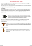
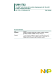
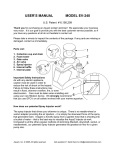
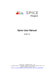
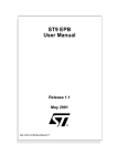
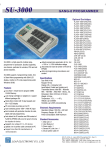
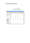
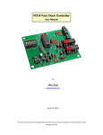
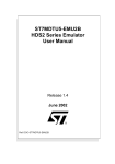
PCB Printing Sheet User Manual
PCB Printing Sheet User Manual
Figure 1: PCB Printing Sheet and fully assembled board in the background
Introduction:
PCB Printing Sheet 28cm x 21.6 is used for quick PCB prototyping. To make the PCB all
you have to do is take printout of the PCB layout on this paper using laser printer, transfer the
print on the PCB using household iron and itch the board using Ferrous Chloride (Fe2Cl3)
solution. With bit of experience you can also make a double sided PCB using this paper. We
have tested this prototyping sheet up to 0.3mm track thickness.
PCB Printing Sheets are available in 3 sizes:
1. PCB Printing Sheet 28cm x 21.6 (A4 size)
2. PCB Printing Sheet 14cm x 21.6 (A4/2 size)
3. PCB Printing Sheet 14cm x 10.3 (A4/4 size)
NEX Robotics Pvt. Ltd.
www.nex-robotics.com
1
PCB Printing Sheet User Manual
Steps involved in making prototype PCB using PCB Printing
Sheet
PCB Printing sheet is made up of Plastic material with loosely coupled polymer coating on
the sheet. When PCB artwork is printed using laser printer, black ink of the toner gets
strongly bonded with the loosely coupled polymers. This process produces thick transfer
material. When PCB Printing Sheet is ironed using household iron on the freshly cleaned
copper clad PCB board, Toner ink sticks on the copper layer of the PCB. After ironing, PCB
Printing Sheet is gently pealed off using force of the slowly flowing cold tap water. Toner ink
from the laser printer containing the artwork which is further reinforced by the bonded
polymer gets transferred on the copper clad PCB. Now PCB can be itched in Ferrous
Chloride (Fe2Cl3) solution. Fe2Cl3 eats away any free copper and only PCB artwork remains
on the PCB. Now PCB is ready for prototyping after cleaning, drilling and cutting.
Step1: PCB artwork designing and print settings
Design PCB artwork using any PCB software. Here we are using Eagle PCB software which
can be downloaded from www.cadsoftusa.com. You can also use any open source free to use
PCB such as “Free PCB” which can be downloaded from http://www.freepcb.com.
Here we have designed PCB for the ATMEGA128 AVR microcontroller having TQFP64
package.
Figure 2: PCB artwork for ATMEGA128 microcontroller socket designed in Eagle
NEX Robotics Pvt. Ltd.
www.nex-robotics.com
2
PCB Printing Sheet User Manual
Note:
• If you are using this process for the first time then do not use track thinner than 1mm.
• If you are going to use simple PCB drill machine then use hole drill diameter 0.4 to
0.6mm irrespective of actual drill size you require. Keep pad diameter greater than
required drill diameter by at least 0.8mm to 1mm. Small drill diameter guides the drill
bit to the centre.
As you gain expertise in using PCB Printing sheet you can push these ratings to the limit. We
use PCB Printing sheet for designing PCBs with track width of 0.3mm, Pads or Vias with
diameter of 0.8mm with drill diameter of 0.4mm. This requires skill and good quality PCB
drill machine.
Before printing the artwork, do the following settings in the PCB software. You will find
these settings at different locations depending on the PCB software that you are using. These
settings make sure that print is of proper quality with 1:1 scaling.
Figure 3: Print settings part I
Layout print settings
1. Keep only those layer active which you want to print
2. Since we are printing the top layer you have to select “Print mirror image” option
3. If you are printing bottom layer then uncheck the “Print mirror image” option
4. Select print option as black and solid; else printer will print the artwork in half tone
pattern.
5. Use scale factor as 1.
6. In the printer settings select paper size as A4 and remove any scale to fit options.
Browse all the tabs of the printer’s print settings. Sometime even if you select A4 in
one of the tab other tab can have “letter” as the option and it will create scaling size
issues in the printing.
7. Select the print location at the centre of the page
NEX Robotics Pvt. Ltd.
www.nex-robotics.com
3
PCB Printing Sheet User Manual
8. After printing keep any component with large pin count on the artwork or use scale to
make sure that artwork is printed in exact 1:1 ratio
Figure 4: Print settings part II
Step 2: Printing the artwork on the PCB Printing Sheet
Print the artwork on any A4 size paper.
Figure 5: Artwork printed on the A4 sized white paper
Cut the PCB Printing Paper with at least 8 to 10mm margin from all the side and stick it just
above the printed artwork on the A4 sheet. Use 10mm or lesser size cello tape. Stick tape
only on the one side as shown in the figure 6. Tape is stuck towards the direction of the entry
of the paper in to the printer. If it is applied in the opposite direct then paper will get jammed
in the printer.
NEX Robotics Pvt. Ltd.
www.nex-robotics.com
4
PCB Printing Sheet User Manual
Important:
• Print the artwork on the rough side of the PCB Printing Sheet.
• Make sure that there is no sticky area on the paper because of cello tape. Sticky area
will damage the laser printer cartridge.
• Keep paper free from dirt or any dust particles. It will damage the toner of the laser
printer.
Figure 6: Stick piece of the PCB Printing Paper just above the artwork with rough
surface on top
Figure 7: PCB Printing Paper after toner ink is transferred
NEX Robotics Pvt. Ltd.
www.nex-robotics.com
5
PCB Printing Sheet User Manual
Step 3: Transferring the print on the PCB board
Take piece of single side copper clad Glass Epoxy PCB having at least 8 to 10mm margins
from all sides. Clean it thoroughly with the fine grade polish paper. Wipe-out fine dust with
clean, dry oil free cloth.
Figure 8: Cleaned copper clad glass epoxy single sided PCB
Put the PCB printing paper on the copper board. Iron it using household iron with
temperature setting set between Nylon and Silk. While ironing put the PCB board on the hard
corrugated cardboard sheet. This will insure that iron applies uniform pressure on all the
surface. When artwork forms good bond with the PCB you can see that the tracks gets darker.
If you apply iron for more time then tracks will get smudged. This is a trial and error process
and you will need few iterations before learning the perfect timings. Iron temperature settings
vary depending on the model. You need to identify optimal settings for your iron.
Figure 9: Transferring artwork on the PCB using household iron
After PCB is cooled, peal off the PCB printing sheet gently under slowly flowing cold tap
water. Use force of the water to separate PCB Printing Sheet form the PCB. In the figure 10
you can see that on the PCB Printing Sheet there are some black patches remaining. Best
quality artwork transfer should not have remaining black patches on the PCB Printing Sheets.
In this case artwork is not transferred properly in the black areas. Look carefully and correct
the faults using permanent marker pen if required. After the artwork is transferred, PCB
Printing Sheet should have least amount of black spots. If artwork transfer process is failed
then you can use the same PCB again after cleaning it with the polish paper. Before and after
cleaning make sure that PCB is dry.
NEX Robotics Pvt. Ltd.
www.nex-robotics.com
6
PCB Printing Sheet User Manual
Figure 10: PCB artwork transferred on the PCB board
Step 4: PCB itching
Put the Ferrous Chloride (Fe2Cl3) powder in the water. Make sure that you use hand gloves
and safety goggles while doing this. Ferrous Chloride is a highly corrosive chemical. It
causes permanent stains on the cloths, flooring etc. Avoid skin contact with the chemical.
Upon accidental contact with the chemical wash immediately. When it dissolves in water it
produces heat with bubbles and sometimes fine particles of Ferrous Chloride gets airborne
which can get accidentally inhaled or go in the eyes. Be very very careful while handling
Ferrous Chloride. Mix the Ferrous Chloride in good plastic container. We have noticed that
when low grade plastic container is used, sometimes small amount of oil appears on the
surface. It forms thin protective layer on the PCB and itching process goes haywire. Ferrous
Chloride (Fe2Cl3) has strong affinity towards water. Make sure that you keep the powder in
tightly closed pack. Discard the Ferrous Chloride if its colour changes to brown. After itching
you can store the solution in air tight good quality plastic bottle.
Figure 11: Ferrous Chloride (Fe2Cl3)
Put the PCB in vertical position. Check the PCB itching status in periodic intervals. If
solution is hot (about 600C), concentrated and chemical is fresh then it can itch the board in
as little as 20 minutes. At room temperature with weaker solution can take even 2 hours. You
can store the solution in air tight good quality plastic bottle for later use.
NEX Robotics Pvt. Ltd.
www.nex-robotics.com
7
PCB Printing Sheet User Manual
Figure 12: PCB itching in Ferrous Chloride (Fe2Cl3)
Figure 13: Itched PCB
Clean the PCB with fine grade polish paper to expose copper artwork.
Figure 14: Itched PCB after cleaning with the polish paper
Cut PCB, drill holes and solder the components. Figure 15 shows the fully assembled board.
In this case we have covered all the copper tracks with the solder to protect copper from
oxidation.
NEX Robotics Pvt. Ltd.
www.nex-robotics.com
8
PCB Printing Sheet User Manual
Figure 15: Fully assembled board
NEX Robotics Pvt. Ltd.
www.nex-robotics.com
9
PCB Printing Sheet User Manual
Written By:
Sachitanand Malewar
NEX Robotics Pvt. Ltd.
Version 1, 2010-10-11
Notice
The contents of this manual are subject to change without notice. All efforts have been made to ensure the
accuracy of contents in this manual. However, should any errors be detected, NEX Robotics welcomes your
corrections. You can send us your queries / suggestions at
[email protected]
Content of this manual is released under the Creative Commence cc by-nc-sa license. For legal information
refer to: http://creativecommons.org/licenses/by-nc-sa/3.0/legalcode
Recycling:
Almost all the part of this product are recyclable. Please send this product to the recycling plant after its
operational life. By recycling we can contribute to cleaner and healthier environment for the future generations.
NEX Robotics Pvt. Ltd.
www.nex-robotics.com
10