1
1. FUNCTIONS
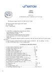
1.1 The SPD-3.2 optical smoke detector is designed to detect smoky fires indoors and to
transmit alarm signal to fire alarm control panels.
1.2 The SPD-3.2 detector is counted on the continuous 24-hours operating in connection with
fire alarm control panels in 4-wire 12 V fire alarm loops.
1.3 The output alarm signal is issued by relay contact breaking.
1.4 The detectors have functions:
- Indication of the standby mode (LED periodical flashing);
- Indication of the alarm mode (LED steady light).
The detector complies with EN 54-7.
2. TECHNICAL SPECIFICATIONS
2.1 Supply voltage range, V..……………………….........….. 12±1,8
2.2 Standby current consumption, mA……..…….. …....≤0,095
2.3 Maximum trigger current, mA ….………..……......… ≤22
2.4 Maximum switching voltage, V…………..……....…...≤36
2.5 Maximum switching current, mA…………..…......…≤100
2.6 N.O. relay contact resistance……………………….....specified by R lim
2.7. N.C. relay contact resistance, Ohm……………...…...≤5
2.8 Dimensions, mm. …….………..…………..............…..….Ø100х48
2.9 Weight, g ……….………………….…..………...................150
2.10 Operating temperature range, °С …...................from - 10 to + 55
2.11 Average lifespan, years. ……….................………....≥10
3. ITEMS SUPPLIED WITH THE DETECTOR
Name
Quantity
Note
SPD-3.2 optical smoke detector
up to 25 pcs
including B103-03 base
Manual
1 pc.
per a package
Package
1 pc.
per 25 pcs.
For installation of the detectors on suspended ceilings you can separately order the K-4
mounting rings.
4. DESIGN AND PRINCIPLES OF OPERATION
4.1 The principle of detector’s operation is based on the control of optical medium
density.
4.2 The detector consists of the detector itself and the base. The optical system, the
signal processing electronic unit and LED control circuit are placed in the plastic housing of the
detector. The detector is connected to a base by a 4-contact joint.
4.3 If there is no smoke in the sensitive zone of the optical system, the detector
connected to the control panel will be in the standby mode, the red LED periodical flashing
indicates about.
4.4 When smoke appears in the sensitive zone of the optical system, the electronic
circuit issues the alarm signal by relay contact breaking that changes AL status. The red LED
switches on in alarm mode.
4.5 The reset f detectors to the standby mode (reset) occurs when the mains supply
switches off for not less than 3 s with the following energizing.
4.6 The contacts “6” and “3” fitted on the base comprise a NC contact if the detector is
installed. When the detector is detached from the base the contact breaks and the ‘fault’ signal
is issued.