1
GDI Target Interface
Revised 09/01/2003
Metrowerks, the Metrowerks logo, and CodeWarrior are registered trademarks of Metrowerks Corp. in the US and/or
other countries. All other tradenames and trademarks are the property of their respective owners.
Copyright © Metrowerks Corporation. 2003. ALL RIGHTS RESERVED.
The reproduction and use of this document and related materials are governed by a license agreement media,
it may be printed for non-commercial personal use only, in accordance with the license agreement related to the
product associated with the documentation. Consult that license agreement before use or reproduction of any
portion of this document. If you do not have a copy of the license agreement, contact your Metrowerks representative or call 800-377-5416 (if outside the US call +1-512-996-5300). Subject to the foregoing non-commercial
personal use, no portion of this documentation may be reproduced or transmitted in any form or by any means,
electronic or mechanical, without prior written permission from Metrowerks.
Metrowerks reserves the right to make changes to any product described or referred to in this document without further
notice. Metrowerks makes no warranty, representation or guarantee regarding the merchantability or fitness of its products for any particular purpose, nor does Metrowerks assume any liability arising out of the application or use of any
product described herein and specifically disclaims any and all liability. Metrowerks software is not authorized for
and has not been designed, tested, manufactured, or intended for use in developing applications where the failure, malfunction, or any inaccuracy of the application carries a risk of death, serious bodily injury, or damage
to tangible property, including, but not limited to, use in factory control systems, medical devices or facilities,
nuclear facilities, aircraft navigation or communication, emergency systems, or other applications with a similar degree of potential hazard.
USE OF ALL SOFTWARE, DOCUMENTATION AND RELATED MATERIALS ARE SUBJECT TO THE
METROWERKS END USER LICENSE AGREEMENT FOR SUCH PRODUCT.
How to Contact Metrowerks
Corporate Headquarters
Metrowerks Corporation
7700 West Parmer Lane
Austin, TX 78729
U.S.A.
World Wide Web
http://www.metrowerks.com
Sales
Voice: 800-377-5416
Fax: 512-996-4910
E-mail: [email protected]
Technical Support
Voice: 800-377-5416
E-mail: [email protected]
Table of Contents
1 Overview
5
About this guide . . . . . . . . . . . . . . . . . . . . . . . . . . . 5
Highlights . . . . . . . . . . . . . . . . . . . . . . . . . . . . . . 6
Requirements . . . . . . . . . . . . . . . . . . . . . . . . . . . . 6
2 Getting Started with CodeWarrior and the HCS12 Serial Monitor,
and more...
7
Technical Considerations about GDI Target Interface . . . . . . . . . . . . . 7
First Steps with CodeWarrior and the HCS12 Serial Monitor via GDI Target Interface
using the Stationery Wizard . . . . . . . . . . . . . . . . . . . . . . 8
First Steps with CodeWarrior and setting HCS12 Serial Monitor via GDI Target
Interface within an existing project . . . . . . . . . . . . . . . . . . 10
3 Getting Started with CodeWarrior and the SofTec InDART-HCS12,
and more...
13
Technical Considerations about GDI Target Interface . . . . . . . . . . . . 13
First Steps with CodeWarrior and the SofTec inDART-HCS12 via GDI Target
Interface using the Stationery Wizard . . . . . . . . . . . . . . . . . 14
First Steps with CodeWarrior and setting SofTec inDART-HCS12 via GDI Target
Interface within an existing project . . . . . . . . . . . . . . . . . . 15
4 GDI Target Interface Manual
Introduction . . . . . . . . . . .
Interfacing Your System with the Target
Hardware Connection . . . . . .
Loading the GDI Target Interface .
GDI Target Interface Menu Entries . .
Load... . . . . . . . . . . . .
Reset . . . . . . . . . . . . .
Connect... . . . . . . . . . . .
19
.
.
.
.
.
.
.
.
.
.
.
.
.
.
.
.
.
.
.
.
.
.
.
.
.
.
.
.
.
.
.
.
.
.
.
.
.
.
.
.
.
.
.
.
.
.
.
.
.
.
.
.
.
.
.
.
.
.
.
.
.
.
.
.
.
.
.
.
.
.
.
.
.
.
.
.
.
.
.
.
.
.
.
.
.
.
.
.
.
.
.
.
.
.
.
.
.
.
.
.
.
.
.
.
.
.
.
.
.
.
.
.
.
.
.
.
.
.
.
.
.
.
.
.
.
.
.
.
.
.
.
.
.
.
.
.
19
20
20
20
22
22
22
22
Command Files . . . . . . . . . . . . . . . . . . . . . . . . . 22
Set Hardware BP... . . . . . . . . . . . . . . . . . . . . . . . . 22
Set Bank... . . . . . . . . . . . . . . . . . . . . . . . . . . . 23
GDI Target Manual
1
Table of Contents
GDI Target Interface Dialogs . . . . . . . . .
GDI Setup. . . . . . . . . . . . . . . .
Status Bar Information for the GDI Target Interface
Status Messages . . . . . . . . . . . . .
Stepping and Breakpoint Messages . . . . . .
GDI Target Interface Default Environment . . . .
Default Target Setup. . . . . . . . . . . .
GDI Target Interface Environment Variables . .
GDI Target Interface Command Line commands. .
.
.
.
.
.
.
.
.
.
.
.
.
.
.
.
.
.
.
.
.
.
.
.
.
.
.
.
.
.
.
.
.
.
.
.
.
.
.
.
.
.
.
.
.
.
.
.
.
.
.
.
.
.
.
.
.
.
.
.
.
.
.
.
.
.
.
.
.
.
.
.
.
.
.
.
.
.
.
.
.
.
.
.
.
.
.
.
.
.
.
.
.
.
.
.
.
.
.
.
.
.
.
.
.
.
.
.
.
5 Supported GDI DLLs
HCS12 Serial Monitor . . . . .
Menu Entries . . . . . . .
Monitor Communication... . .
Load Options... . . . . . . .
Erase Flash . . . . . . . .
Trigger Module Settings . . .
Bus Trace . . . . . . . . .
Monitor Setup Dialog . . . .
SofTec inDART-HCS12 . . . .
Menu Entries . . . . . . .
MCU Configuration . . . . .
About . . . . . . . . . .
Trigger Module Settings . . .
Bus Trace . . . . . . . . .
MCU Configuration dialog . .
Communication Settings dialog
About dialog. . . . . . . .
23
23
25
25
26
27
27
27
29
33
.
.
.
.
.
.
.
.
.
.
.
.
.
.
.
.
.
.
.
.
.
.
.
.
.
.
.
.
.
.
.
.
.
.
.
.
.
.
.
.
.
.
.
.
.
.
.
.
.
.
.
.
.
.
.
.
.
.
.
.
.
.
.
.
.
.
.
.
.
.
.
.
.
.
.
.
.
.
.
.
.
.
.
.
.
.
.
.
.
.
.
.
.
.
.
.
.
.
.
.
.
.
.
.
.
.
.
.
.
.
.
.
.
.
.
.
.
.
.
6 HC12 and HCS12 Banked Memory support
.
.
.
.
.
.
.
.
.
.
.
.
.
.
.
.
.
.
.
.
.
.
.
.
.
.
.
.
.
.
.
.
.
.
.
.
.
.
.
.
.
.
.
.
.
.
.
.
.
.
.
.
.
.
.
.
.
.
.
.
.
.
.
.
.
.
.
.
.
.
.
.
.
.
.
.
.
.
.
.
.
.
.
.
.
.
.
.
.
.
.
.
.
.
.
.
.
.
.
.
.
.
.
.
.
.
.
.
.
.
.
.
.
.
.
.
.
.
.
.
.
.
.
.
.
.
.
.
.
.
.
.
.
.
.
.
.
.
.
.
.
.
.
.
.
.
.
.
.
.
.
.
.
.
.
.
.
.
.
.
.
.
.
.
.
.
.
.
.
.
.
.
.
.
.
.
.
.
.
.
.
.
.
.
.
.
.
.
.
.
.
.
.
.
.
.
.
.
.
.
.
.
.
.
33
33
34
34
34
34
34
35
37
37
38
38
38
38
39
40
42
43
Banked Memory Location Dialog Box. . . . . . . . . . . . . . . . . . 43
PPAGE index tab . . . . . . . . . . . . . . . . . . . . . . . . . 44
DPAGE index tab . . . . . . . . . . . . . . . . . . . . . . . . . 45
2
GDI Target Manual
Table of Contents
EPAGE index tab . . . . . . . . . . .
Various index tab (not all Target Interfaces)
Associated Commands . . . . . . . . . .
Associated Environment Variables . . . . .
.
.
.
.
.
.
.
.
.
.
.
.
.
.
.
.
.
.
.
.
.
.
.
.
.
.
.
.
.
.
.
.
.
.
.
.
.
.
.
.
.
.
.
.
.
.
.
.
.
.
.
.
.
.
.
.
7 Target Interface Commands Files
Target Interface Associated Command Files
Startup Command File . . . . . . . .
Reset Command File . . . . . . . .
Preload Command File. . . . . . . .
Postload Command File . . . . . . .
Vppon Command File . . . . . . . .
Vppoff Command File . . . . . . . .
Command Files dialog . . . . . . . . .
Associated Commands . . . . . . . . .
Associated Environment Variables . . . .
55
.
.
.
.
.
.
.
.
.
.
.
.
.
.
.
.
.
.
.
.
.
.
.
.
.
.
.
.
.
.
.
.
.
.
.
.
.
.
.
.
.
.
.
.
.
.
.
.
.
.
.
.
.
.
.
.
.
.
.
.
.
.
.
.
.
.
.
.
.
.
.
.
.
.
.
.
.
.
.
.
.
.
.
.
.
.
.
.
.
.
.
.
.
.
.
.
.
.
.
.
.
.
.
.
.
.
.
.
.
.
.
.
.
.
.
.
.
.
.
.
.
.
.
.
.
.
.
.
.
.
.
.
.
.
.
.
.
.
.
.
.
.
.
.
.
.
.
.
.
.
8 On-Chip Hardware Breakpoint Module
Hardware Breakpoint Configuration dialog .
Disabled mode . . . . . . . . . . .
Automatic (controlled by debugger) mode
User Controlled mode . . . . . . . .
Associated Commands . . . . . . . . .
Associated Environment Variables . . . .
45
46
47
51
55
56
56
56
57
57
57
58
59
61
65
.
.
.
.
.
.
.
.
.
.
.
.
.
.
.
.
.
.
.
.
.
.
.
.
.
.
.
.
.
.
.
.
.
.
.
.
.
.
.
.
.
.
.
.
.
.
.
.
.
.
.
.
.
.
.
.
.
.
.
.
.
.
.
.
.
.
.
.
.
.
.
.
.
.
.
.
.
.
.
.
.
.
.
.
.
.
.
.
.
.
65
67
67
68
71
75
Index
1
GDI Target Manual
3
Table of Contents
4
GDI Target Manual
1
Overview
About this guide
This document includes information to become familiar with the GDI Target Interface
and to help you understand how to use this Target Interface. This document is divided
into following sections:
• The Introduction section introduces the GDI Target Interface concept.
• The Getting Started with CodeWarrior and the HCS12 Serial Monitor, and
more... section gives answers for common questions and describes how to use
advanced features of the HCS12 Serial Monitor via GDI Target Interface.
• The Getting Started with CodeWarrior and the SofTec InDART-HCS12, and
more... section gives answers for common questions and describes how to use
advanced features of the SofTec inDART-HCS12 via GDI Target Interface.
• The Interfacing Your System with the Target section contains information about
the connection between the 3rd party debugging hardware and the debugger.
• The GDI Target Interface Menu Entries section gives a description of the GDI
Target Interface specific menu entries.
• The GDI Target Interface Dialogs section gives a description of the GDI Target
Interface specific dialog boxes.
• The Status Bar Information for the GDI Target Interface section describes the
status bar messages for the GDI Target Interface.
• The GDI Target Interface Default Environment section lists all the variables used
by this Target Interface to store the configuration.
• The GDI Target Interface Command Line commands section lists all the
commands specific to this Target Interface.
• The Supported GDI DLLs section introduces current GDI DLLs, i.e. the HCS12
Serial Monitor and the SofTec inDART-HCS12.
• The HC12 and HCS12 Banked Memory support section explains who to set/
change code and data banks for HC12 and HCS12 derivatives.
GDI Target Manual
5
Overview
Highlights
• The Target Interface Commands Files section gives a description of the debugger
command private files.
• The On-Chip Hardware Breakpoint Module section explains how to use the
Hardware Breakpoint Configuration dialog to set hardware breakpoints and
watchpoints.
• The Index contains all keywords of the GDI Target Interface.
Highlights
• The GDI Target Interface allows you to debug with a 3rd party GDI DLL driver
interface: The Metrowerks 8/16 bits debugger (and then the Metrowerks
CodeWarrior IDE) might be connected to HC12 and HCS12 hardware using the
Generic Debug Instrument Interface (Revision 1.2.6). A GDI DLL can be loaded
via the GDI.TGT Target Interface. The GDI DLL must be compliant to the
“Metrowerks 8/16 bits debugger Connection to Debug Instrument Using GDI
interface protocol“ specification. For more information on GDI DLL
implementation and connection to the Metrowerks 8/16 bits debugger, please
contact Metrowerks.
•
Requirements
In order to use the GDI Target Interface, please make sure that the 3rd Party GDI DLL
driver has been installed. The GDI Target Interface can then be setup to open the 3rd
Party GDI DLL. Note that this DLL can have a different name than GDI.DLL. For
more information, please see section Interfacing Your System with the Target.
6
GDI Target Manual
2
Getting Started with
CodeWarrior and the
HCS12 Serial Monitor, and
more...
Thanks for choosing CodeWarrior. This section guides you through installation,
licensing/registration and first steps with CodeWarrior and the HCS12 Serial Monitor
via GDI Target Interface. It does not replace all the documentation provided, but gives
you a good starting point.
Technical Considerations about GDI
Target Interface
The Metrowerks 8/16 bits debugger (and then the Metrowerks CodeWarrior IDE)
might be connected to HCS12 hardware using the Generic Debug Instrument Interface
(Revision 1.2.6). A GDI DLL can be loaded via the GDI.TGT Target Interface. The
GDI DLL must be compliant to the “Metrowerks 8/16 bits debugger Connection to
Debug Instrument Using GDI interface protocol“ specification. For more information
on GDI DLL implementation and connection to the Metrowerks 8/16 bits debugger,
please contact Metrowerks.
The HCS12 Serial Monitor hcs12serialmon.dll is a GDI DLL compliant and loadable
via the GDI Target Interface in CodeWarrior. This GDI DLL implements
communication specifications described in the HCS12 Serial Monitor Application
Note from Motorola, Inc.
When the debugger runs the hcs12serialmon.dll within the GDI Target Interface, it
can communicate and debug hardware running the HCS12 Serial Monitor in full
compliancy to the Motorola HCS12 Serial Monitor Application Note specifications.
GDI Target Manual
7
Getting Started with CodeWarrior and the HCS12 Serial Monitor, and more...
First Steps with CodeWarrior and the HCS12 Serial Monitor via GDI Target Interface using the Stationery
Please refer to this Application Note for communication hardware requirements.
For more detail about the HCS12 Serial Monitor GDI dll, please see HCS12 Serial
Monitor section.
First Steps with CodeWarrior and the
HCS12 Serial Monitor via GDI Target
Interface using the Stationery Wizard
1. Run the CodeWarrior IDE with the shortcut created in the program group.
2. Choose the menu File > New to create a new project from a stationery.
3. Select HC(S)12 New Project Wizard, type in a project name and specify the
project location. Press OK.
4. Please follow all wizard steps and make sure to select the Motorola Serial
Monitor Hardware Debugging as connection.
8
GDI Target Manual
Getting Started with CodeWarrior and the HCS12 Serial Monitor, and more...
First Steps with CodeWarrior and the HCS12 Serial Monitor via GDI Target Interface using the Stationery
Figure 2.1 Wizard Connection Selection
5. Choose the menu Project > Debug to start the debugger.
6. Now in the Monitor Setup dialog, choose the correct Host serial communication
port if necessary. In the Load Options panel, you can specify not to program
automatically your application (by default, mass erasing and flashing of target
processor).
Figure 2.2 Monitor Setup Dialog
GDI Target Manual
9
Getting Started with CodeWarrior and the HCS12 Serial Monitor, and more...
First Steps with CodeWarrior and setting HCS12 Serial Monitor via GDI Target Interface within an existing
7. Press the OK button to start debugging.
First Steps with CodeWarrior and setting
HCS12 Serial Monitor via GDI Target
Interface within an existing project
1. Run the CodeWarrior IDE with the shortcut created in the program group.
2. Open the project.
3. Choose the menu Project > Debug to start the debugger.
4. Choose in the debugger menu Component > Set Target... to select another
target interface.
Figure 2.3 GDI Target Interface Selection
10
GDI Target Manual
Getting Started with CodeWarrior and the HCS12 Serial Monitor, and more...
First Steps with CodeWarrior and setting HCS12 Serial Monitor via GDI Target Interface within an existing
5. Now in the GDI Setup dialog, press the browse button and browse for the
hcs12serialmon dll file.
Figure 2.4 Browse for HCS12SerialMon GDI DLL
6. Now in the Monitor Setup dialog, choose the correct Host serial communication
port if necessary. In the Load Options panel, you can specify not to mass erase
automatically the target processor before flashing (by default, mass erasing is
performed).
Figure 2.5 Monitor Setup Dialog
GDI Target Manual
11
Getting Started with CodeWarrior and the HCS12 Serial Monitor, and more...
First Steps with CodeWarrior and setting HCS12 Serial Monitor via GDI Target Interface within an existing
7. Press the OK button to start debugging.
12
GDI Target Manual
3
Getting Started with
CodeWarrior and the
SofTec InDART-HCS12,
and more...
Thanks for choosing CodeWarrior. This section guides you through installation,
licensing/registration and first steps with CodeWarrior and the SofTec inDART-HCS12
via GDI Target Interface. It does not replace all the documentation provided, but gives
you a good starting point.
Technical Considerations about GDI
Target Interface
The Metrowerks 8/16 bits debugger (and then the Metrowerks CodeWarrior IDE)
might be connected to HCS12 hardware using the Generic Debug Instrument Interface
(Revision 1.2.6). A GDI DLL can be loaded via the GDI.TGT Target Interface. The
GDI DLL must be compliant to the “Metrowerks 8/16 bits debugger Connection to
Debug Instrument Using GDI interface protocol” specification. For more information
on GDI DLL implementation and connection to the Metrowerks 8/16 bits debugger,
please contact Metrowerks.
The SofTec_BDM12.dll is a GDI DLL compliant and loadable via the GDI Target
Interface in CodeWarrior. This GDI DLL is the driver for SofTec inDART_HCS12 incircuit debugger/programmer unit.
When the debugger runs the SofTec_BDM12.dll within the GDI Target Interface, it
can communicate and debug hardware connected through the SofTec in-circuit
debugger/programmer unit.
GDI Target Manual
13
Getting Started with CodeWarrior and the SofTec InDART-HCS12, and more...
First Steps with CodeWarrior and the SofTec inDART-HCS12 via GDI Target Interface using the
Please refer to “inDART®-HCS12In-Circuit Debugger/Programmer for Motorola
HCS12 Family FLASH Devices User’s Manual” from SofTec for communication
hardware requirements and SofTec product installation.
For more detail about the HCS12 Serial Monitor GDI dll, please see SofTec inDARTHCS12 section.
First Steps with CodeWarrior and the
SofTec inDART-HCS12 via GDI Target
Interface using the Stationery Wizard
1. Run the CodeWarrior IDE with the shortcut created in the program group.
2. Choose the menu File > New to create a new project from a stationery.
3. Select HC(S)12 New Project Wizard, type in a project name and specify the
project location. Press OK.
4. Please follow all wizard steps and make sure to select the inDART-HCS12
Hardware Debugging as connection.
14
GDI Target Manual
Getting Started with CodeWarrior and the SofTec InDART-HCS12, and more...
First Steps with CodeWarrior and setting SofTec inDART-HCS12 via GDI Target Interface within an
Figure 3.1 Wizard Connection Selection
5. Choose the menu Project > Debug to start the debugger.
First Steps with CodeWarrior and setting
SofTec inDART-HCS12 via GDI Target
Interface within an existing project
1. Run the CodeWarrior IDE with the shortcut created in the program group.
2. Open the project.
3. Choose the menu Project > Debug to start the debugger.
4. Choose in the debugger menu Component > Set Target... to select another
target interface.
Figure 3.2 GDI Target Interface Selection
GDI Target Manual
15
Getting Started with CodeWarrior and the SofTec InDART-HCS12, and more...
First Steps with CodeWarrior and setting SofTec inDART-HCS12 via GDI Target Interface within an
5. Now in the GDI Setup dialog, press the browse button and browse for the
SofTec_BDM12 dll file. Search for the SofTec_BDM12 dll where SofTec
applications and drivers are installed.
Figure 3.3 Browse for SofTec_BDM12.dll GDI DLL
6. When the SofTec_BDM12 dll is found, press OK. Please choose in the MCU
Configuration dialog the correct target processor.
Figure 3.4 MCU Configuration
16
GDI Target Manual
Getting Started with CodeWarrior and the SofTec InDART-HCS12, and more...
First Steps with CodeWarrior and setting SofTec inDART-HCS12 via GDI Target Interface within an
7. Press the OK button to start debugging.
GDI Target Manual
17
Getting Started with CodeWarrior and the SofTec InDART-HCS12, and more...
First Steps with CodeWarrior and setting SofTec inDART-HCS12 via GDI Target Interface within an
18
GDI Target Manual
4
GDI Target Interface
Manual
Introduction
An advanced feature of Metrowerks debugger for the embedded systems development
world is the ability to load different Target Interfaces, which implements the interface
with target systems. In this document, the specific features of the GDI Target Interface
are described.
The Metrowerks 8/16 bits debugger (and then the Metrowerks CodeWarrior IDE)
might be connected to HC12 and HCS12 hardware using the Generic Debug
Instrument Interface (Revision 1.2.6). A GDI DLL can be loaded via the GDI.TGT
Target Interface. The GDI DLL must be compliant to the “Metrowerks 8/16 bits
debugger Connection to Debug Instrument Using GDI interface protocol”
specification. For more information on GDI DLL implementation and connection to
the Metrowerks 8/16 bits debugger, please contact Metrowerks.
With this interface, you can download an executable program from the Metrowerks
CodeWarrior HC12 Studio, to an external target system based on a Motorola HC12 or
HCS12, which will execute the program. You will also have the feedback of the real
target system behavior to Metrowerks debugger.
The debugger will fully supervise and monitor the MCU of the target system i.e.
control the CPU execution. You can read and write in internal/external memory when
the MCU is in Background Mode. You have full control over the CPU state with the
possibility to stop execution, to proceed in single step mode and to set breakpoints in
the code.
GDI Target Manual
19
GDI Target Interface Manual
Interfacing Your System with the Target
Interfacing Your System with the Target
Hardware Connection
The GDI Target Interface is by definition a Generic Debug Instrument interface. There
is no specific hardware cable or else for this interface. Indeed, the debugging hardware
is entirely bound to the GDI DLL loaded by the GDI target. Please refer to the GDI
DLL designer/provider/3rd party to get details about hardware connections and setup.
Loading the GDI Target Interface
Usually the target is set in the [HI-WAVE] section of the PROJECT file, through the
statement Target=GDI.
In this way, the GDI Target Interface detects automatically that the target is connected
to your system.
If no target is set in the PROJECT file or if a different target is set, you can load the
GDI Target Interface.
Select in the main menu Component > Set Target..., as shown in Figure 3.3.
Figure 4.1 Set Target dialog
The Set Target dialog is displayed. Choose GDI Target Interface in the list of
proposed targets and click OK.
20
GDI Target Manual
GDI Target Interface Manual
Interfacing Your System with the Target
Figure 4.2 List of available targets interfaces
Once the GDI Target interface is loaded, the GDI Setup dialog is opened. A GDI DLL
must be specified in the “Path and name of the GDI DLL” edit box. Pressing the
Browse button opens a typical Windows file browser.
Figure 4.3 GDI Setup dialog
Once the GDI DLL is specified press OK, then follow specific setup requirements of
the loaded GDI DLL.
GDI Target Manual
21
GDI Target Interface Manual
GDI Target Interface Menu Entries
GDI Target Interface Menu Entries
After loading the GDI Target Interface, the Target menu item is replaced by GDI. The
different entries of the GDI menu are described below:
Figure 4.4 GDI Menu entries.
Load...
Choose GDI > Load... to load the application to debug, i.e. e.g. a .abs file. Note that
this operation is only possible when a GDI DLL has been loaded. Also, in this case,
the “GDI” menu entry gets the name of the GDI DLL loaded.
Reset
The menu entry GDI > Reset executes the Reset Command File and resets the target
system processor.
Connect...
Select entry GDI > Connect... to display the GDI Setup dialog.
Command Files
Select entry GDI > Command Files to display the GDI Target Interface Command
Files dialog.
Set Hardware BP...
This is a generic menu entry is only displayed and only accessible after a GDI DLL
has been successfully loaded. Also this menu entry is available only if the connection
with the target system has been established.
22
GDI Target Manual
GDI Target Interface Manual
GDI Target Interface Dialogs
Choose GDI > Set Hardware BP... to open the Hardware Breakpoint Configuration
dialog.
Set Bank...
This is a generic menu entry is only displayed and only accessible after a GDI DLL
has been successfully loaded. Also this menu entry is available only if the connection
with the target system has been established.
Choose GDI > Set Bank... to open the Banked Memory Location Dialog Box.
GDI Target Interface Dialogs
This section describes the dialogs which are specific to the GDI Target Interface.
Those dialogs are:
• the GDI Setup dialog,
• the GDI Target Interface Command Files dialog,
• the Hardware Breakpoint Configuration dialog,
• the Banked Memory Location Dialog Box,
GDI Setup
Select entry GDI > Connect... to display the GDI Setup dialog.
GDI Target Manual
23
GDI Target Interface Manual
GDI Target Interface Dialogs
Figure 4.5 GDI Setup dialog.
A GDI DLL must be specified in the “Path and name of the GDI DLL” edit box.
Pressing the Browse button opens a typical Windows file browser.
Figure 4.6 GDI DLL browser.
24
GDI Target Manual
GDI Target Interface Manual
Status Bar Information for the GDI Target Interface
Status Bar Information for the GDI Target
Interface
When a GDI DLL has been loaded, specific information belonging to the GDI dll are
displayed in the debugger’s status bar. If no GDI dll is loaded, “No link to Target”
default message is displayed.
Figure 4.7 Status bar GDI default message
Status Messages
GDI ready
Metrowerks debugger is ready and waits until a new target or application is loaded.
This message is generated once the Metrowerks debugger has been started and the
connection to target system has been established.
No Link To Target
No GDI dll is currently loaded or currently loaded GDI dll connection to the target
system has failed.
RUNNING
The application is currently executing on the target.
HALTED
Execution of the application has been stopped on user request. The menu entry Run >
Halt or the Halt icon in the tool bar has been selected.
RESET
This message is generated when the Metrowerks debugger has been reset on user
request. The menu entry GDI > Reset or the Reset icon in the tool bar has been
selected, or the command Reset has been used.
GDI Target Manual
25
GDI Target Interface Manual
Status Bar Information for the GDI Target Interface
Stepping and Breakpoint Messages
STEPPED
Execution of the application has been stopped after a single step on source level. The
menu entry Run> Single Step or the Single Step icon in the tool bar has been
selected.
STEPPED OVER
Execution of the application has been stopped after a step over a function call. The
menu entry Run > Step Over or the Step Over icon in the tool bar has been selected.
STOPPED
Execution of the application has been stopped after a step out from function call. The
menu entry Run> Step Out or the Step Out icon in the tool bar has been selected.
TRACED
Execution of the application has been stopped after an single step on assembler level.
The menu entry Run > Assembly Step or the Assembly Step icon in the tool bar has
been selected.
BREAKPOINT
Execution of the application has been stopped because a breakpoint has been reached.
WATCHPOINT
Execution of the application has been stopped because a watchpoint has been reached.
26
GDI Target Manual
GDI Target Interface Manual
GDI Target Interface Default Environment
GDI Target Interface Default Environment
Default Target Setup
As any other target, the GDI Target Interface can be loaded from the Target menu or
can be set as a default target in the PROJECT file which should be located in the
working directory.
Typically the target is set in the [HI-WAVE] section from the PROJECT file as shown
above. However, if the target is not defined, yo can load the GDI Target Interface
interactively. Please refer to section Loading the GDI Target Interface of this manual.
Listing 4.1 Example of [HI-WAVE] section from PROJECT file:
[HI-WAVE]
Window0=Source
Window1=Assembly
Window2=Procedur
Window3=Register
Window4=Memory
Window5=Data
Window6=Data
Target=GDI
NOTE
0
60
0
60
60
0
0
0
0
30
30
60
55
78
60
40
60
40
40
60
60
30
30
25
30
40
23
22
Please see the Manual Engine HC12.pdf for further information
about the PROJECT file.
GDI Target Interface Environment Variables
This section describes the environment variables which are used by the GDI Target
Interface.
The GDI Target Interface specific environment variables are:
• COMSETTINGS
Some other common GDI dlls features are using variables. Those variables are:
• BNKA_MCUIDnnnn_BANKWINDOWn
• CMDFILEn
• HWBPD_MCUIDnnn_BKPT_REMAPn
GDI Target Manual
27
GDI Target Interface Manual
GDI Target Interface Default Environment
• HWBPD_MCUIDnnnn_HBPMn
These variables are stored in the [GDI]section from the PROJECT file.
Listing 4.2 Example of [GDI] section from PROJECT file:
[GDI]
COMSETTINGS=SETCOMM DRIVER NOPROTOCOL NOPERIODICAL "hcs12serialmon.dll"
COMSETTINGS
Short Description
Communication device settings
Syntax
COMSETTINGS==SETCOMM DRIVER <PROTOCOL|NOPROTOCOL>
<PERIODICAL|NOPERIODICAL> "<GDI DLL file (and path)>"
Alias
None
File
PROJECT file
Section
[GDI]
Components
GDI Target Interface.
Description
The communication port to be used on the host computer can be specified using the
variable COMSETTINGS.
If PROTOCOL is specified, all the commands and responses sent and received are
reported in the Command Line component of the debugger. If NOPROTOCOL is
specified, no protocol is reported.
28
GDI Target Manual
GDI Target Interface Manual
GDI Target Interface Command Line commands
If PERIODICAL and NOPERIODICAL are not used in the GDI target interface.
All parameters are set according to the setup in the GDI Setup dialog.
For example,
COMSETTINGS=SETCOMM DRIVER NOPROTOCOL NOPERIODICAL
"hcs12serialmon.dll"
GDI Target Interface Command Line
commands
This section describes the GDI Target Interface specific commands which can be used
when the GDI Target Interface is set.
The GDI Target Interface specific commands are:
• PROTOCOL
• RESET
Some other common Target Interface features are using commands. Those commands
are:
• BANKWINDOW
• HWBPM
• CMDFILE
Those commands can be entered in the file or in the Command Line component of the
debugger.
PROTOCOL
Short Description
switch on/off the Show Protocol functionality
Syntax
PROTOCOL ON|OFF
GDI Target Manual
29
GDI Target Interface Manual
GDI Target Interface Command Line commands
Alias
None
Components
GDI Target Interface.
Description
If this command is used, all the messages sent to and received from the GDI interface
are reported in the Command Line window of the debugger.
For Example
PROTOCOL ON
TIP
The Show Protocol is a useful debugging feature if there is a
communication problem.
RESET
Short Description
reset of the target board
Syntax
RESET
Alias
None
Components
GDI Target Interface.
30
GDI Target Manual
GDI Target Interface Manual
GDI Target Interface Command Line commands
Description
With this command it is possible to reset the target from the Command Line
component of the debugger.
For example,
RESET
GDI Target Manual
31
GDI Target Interface Manual
GDI Target Interface Command Line commands
32
GDI Target Manual
5
Supported GDI DLLs
HCS12 Serial Monitor
The HCS12 Serial Monitor hcs12serialmon.dll is a GDI DLL compliant and loadable
via the GDI Target Interface in CodeWarrior. This GDI DLL implements
communication specifications described in the HCS12 Serial Monitor Application
Note from Motorola, Inc.
When the debugger runs the hcs12serialmon.dll within the GDI Target Interface, it
can communicate and debug hardware running the HCS12 Serial Monitor in full
compliancy to the Motorola HCS12 Serial Monitor Application Note specifications.
Please refer to this Application Note for communication hardware requirements.
Menu Entries
Once the hcs12serialmon.dll is loaded in the GDI target interface, the “GDI” menu
entry is replaced by “MONITOR-HCS12”.
Figure 5.1 Menu Entries
Only specific HCS12 Serial Monitor entries are commented here. Regular menu
entries are introduce in GDI Target Interface Menu Entries. As shown above, menu
GDI Target Manual
33
Supported GDI DLLs
HCS12 Serial Monitor
entries are not always identical. The left hand side menu is displayed when the target
processor does not include the onchip DBG module and features. The right hand side
menu is displayed when the target processor includes the onchip DBG module and
features. Please refer to the “Debugger HCS12 Onchip DBG Module User Interface”
manual to get find all related information.
Monitor Communication...
Select entry MONITOR-HCS12> Communications... to display the Monitor Setup
Dialog on Monitor Communication tab.
Load Options...
Select entry MONITOR-HCS12> Load Options... to display the Monitor Setup
Dialog on Load Options tab.
Erase Flash
Select entry MONITOR-HCS12> Erase Flash to force immediate mass erase of the
target processor flash.
Trigger Module Settings
Select entry MONITOR-HCS12> Trigger Module Settings... to force immediate
mass erase of the target processor flash. Please refer to the “Debugger HCS12 Onchip
DBG Module User Interface” manual to get find all related information.
Bus Trace
Select entry MONITOR-HCS12> Bus Trace to open the Trace window component.
Please refer to the “Debugger HCS12 Onchip DBG Module User Interface” manual
to get find all related information.
34
GDI Target Manual
Supported GDI DLLs
HCS12 Serial Monitor
Monitor Setup Dialog
The Monitor Setup dialog has two tabs, has shown below.
Figure 5.2 Monitor Communication tab
Within this tab, it is possible to set or modify the current serial communication port
when opening the “HOST Serial Communication Port” drop down list. Checking
“Show Monitor TX/RX” reports in the debugger Command Line window all low level
communication frames between the host computer and the HCS12 Serial Monitor.
Figure 5.3 Load Options tab
GDI Target Manual
35
Supported GDI DLLs
HCS12 Serial Monitor
Within this tab, unchecking “Enable Automatic Erase Flash on Load” avoids mass
erasing the target processor before flashing the application, operation which is
performed by default. It is therefore possible to flash several applications. However, it
is the user responsibility to avoid flash/code overwriting.
36
GDI Target Manual
Supported GDI DLLs
SofTec inDART-HCS12
SofTec inDART-HCS12
The SofTec_BDM12.dll is a GDI DLL compliant and loadable via the GDI Target
Interface in CodeWarrior. This GDI DLL is the driver for SofTec inDART_HCS12 incircuit debugger/programmer unit.
When the debugger runs the SofTec_BDM12.dll within the GDI Target Interface, it
can communicate and debug hardware connected through the SofTec in-circuit
debugger/programmer unit.
Please refer to “inDART®-HCS12 In-Circuit Debugger/Programmer for Motorola
HC12 and HCS12 Family FLASH Devices User’s Manual” from SofTec for
communication hardware requirements and SofTec product installation.
Menu Entries
Once the SofTec_BDM12.dll is loaded in the GDI target interface, the “GDI” menu
entry is replaced by “inDART-HCS12”.
Figure 5.4 Menu Entries
Only specific inDART-HCS12 entries are commented here. Regular menu entries are
introduce in GDI Target Interface Menu Entries. As shown above, menu entries are
not always identical. The left hand side menu is displayed when the target processor
does not include the onchip DBG module and features. The right hand side menu is
displayed when the target processor includes the onchip DBG module and features.
Please refer to the “Debugger HCS12 Onchip DBG Module User Interface” manual
to get find all related information.
GDI Target Manual
37
Supported GDI DLLs
SofTec inDART-HCS12
MCU Configuration
Select entry inDART-HCS12> MCU Configuration to display the MCU
Configuration dialog.
About
Select entry inDART-HCS12> About... to display the About dialog.
Trigger Module Settings
Select entry inDART-HCS12> Trigger Module Settings... to force immediate
mass erase of the target processor flash. Please refer to the “Debugger HCS12 Onchip
DBG Module User Interface” manual to get find all related information.
Bus Trace
Select entry inDART-HCS12> Bus Trace to open the Trace window component.
Please refer to the “Debugger HCS12 Onchip DBG Module User Interface” manual
to get find all related information.
38
GDI Target Manual
Supported GDI DLLs
SofTec inDART-HCS12
MCU Configuration dialog
The Hardware Model drop down list can be expanded to select another type of BDM
debug interface than the inDART-HCS12. Note that at this document release time,
only the inDART-HCS12 is available.
The Device Code drop down list can be expanded to select another HCS12 derivative.
Pressing the Communication Settings button opens the Communication Settings
dialog.
Figure 5.5 MCU Configuration dialog
GDI Target Manual
39
Supported GDI DLLs
SofTec inDART-HCS12
Communication Settings dialog
The Bus Clock Selection group is intended to setup the best BDM synchronization
between the inDART-HCS12 interface and the target processor. If the target hardware
provides a BDM synchronization clock signal, the inDART-HCS12 ECLK line should
be used and connected to this line to get the most precise synchronization.
In other cases, the Automatic Detection option can be specified. The user can also
specify manually a BDM frequency (usually (external oscillator frequency/2)).
pressing the Find button makes the inDART-HCS12 driver search and display the
current BDM frequency.
Note that the manual frequency option is not compatible with application changing the
target processor bus speed via the onchip PLL. Indeed, the BDM communication
clock is derived from the device bus clock. Please use Automatic Detection or ECLK
signal options for this purpose.
The BDM Clock group and radio button options are rather bound to derivatives having
synchronization problems. Please check the target processor errata sheet if BDM
communication problems occur when the application changes the target processor bus
speed via the onchip PLL.
Please refer to “inDART®-HCS12 In-Circuit Debugger/Programmer for Motorola
HC12 and HCS12 Family FLASH Devices User’s Manual” from SofTec for further
details.
40
GDI Target Manual
Supported GDI DLLs
SofTec inDART-HCS12
Figure 5.6 Communication Settings dialog
GDI Target Manual
41
Supported GDI DLLs
SofTec inDART-HCS12
About dialog
This dialog belongs to the SofTec GDI dll and provides information about the
SofTec_BDM12.dll release and version.
Figure 5.7 About dialog
42
GDI Target Manual
6
HC12 and HCS12 Banked
Memory support
The PPAGE, DPAGE and the EPAGE banked memory location are supported by the
Metrowerks debugger Target Interfaces, depending on the debugged application and
on the debugged HC12/HCS12 derivative.
Banked Memory Location Dialog Box
The Banked Memory Location dialog box is available only if the connected derivative
is a Motorola HC12 (CPU12) or HCS12.
The Banked Memory Location dialog box can be opened by selecting the menu entry
“TargetName” > Set Bank.... (In this section, TargetName is the name of the
Target Interface, like SDI, Hitex, BDIK, GDI, Noral-BDM, etc.) Using some Target
Interfaces, the Banked Memory Location dialog box automatically pops up when the
Target Interface is used with a Motorola HC12 or HCS12 derivative that supports
banking. In this case, it also pops up when the banked memory area locations are not
defined in the project file of the current project directory.
In this dialog box you can define which banked memory you want to use and its
location. The PPAGE, DPAGE and the EPAGE indexes are supported, if they are
available on the currently connected HC12 or HCS12 derivative.
The Banked Memory Location dialog box can have up to four index tabs:
• The PPAGE index tab,
• The DPAGE index tab,
• The EPAGE index tab,
• The Various index tab (not all Target Interfaces).
GDI Target Manual
43
HC12 and HCS12 Banked Memory support
Banked Memory Location Dialog Box
PPAGE index tab
The PPAGE index tab of the Banked Memory Location dialog box lets you set up the
PPAGE banked memory area.
Figure 6.1 Banked Memory Location dialog (PPAGE index tab)
Once you have enabled PPAGE memory banking by checking the Enable Banked
Memory Area check box, you must set the start address and the end address of this
memory range.
The PPAGE register address must be specified in hexadecimal (e.g. 0x35 for
HC812A4, 0xFF for HC912DG128, 0x30 for MC9S12/HCS12 devices).
The first page number must be specified in hexadecimal. (e.g. 0x30 for devices with
S12FTS256K flash, 0x38 for devices with S12FTS128K flash, 0x3C for devices with
S12FTS64K flash, 0x0 for HC912DG128).
The number of pages must be specified in decimal (e.g. 0 to 256 for HC812A4, 8 for
HC912DG128, 16 for devices with S12FTS256K flash, 8 for devices with
S12FTS128K flash, 4 for devices with S12FTS64K flash).
NOTE
44
For the Hitex Target Interface, the PPAGE index tab does not appear
in this dialog box if the PPAGE register is not available on the
currently connected Motorola HC12 derivative. For this Target
Interface it is not needed to enter the PPAGE register address.
GDI Target Manual
HC12 and HCS12 Banked Memory support
Banked Memory Location Dialog Box
DPAGE index tab
The DPAGE index tab of the Banked Memory Location dialog box lets you set up the
DPAGE banked memory area.
Figure 6.2 Banked Memory Location dialog (DPAGE index tab)
Once you have enabled DPAGE memory banking by checking the Enable Banked
Memory Area check box, you must set the start address and the end address of this
memory range.
The first page number must be specified in hexadecimal (e.g. 0 for HC812A4).
The number of pages must be specified in decimal (e.g. 0 to 256 for HC812A4).
The DPAGE register address must be specified in hexadecimal (e.g. 0x34 for
HC812A4).
NOTE
For the Hitex Target Interface, the DPAGE index tab does not appear
in this dialog box if the DPAGE register is not available on the
currently connected Motorola HC12 derivative. For this Target
Interface it is not needed to enter the DPAGE register address.
EPAGE index tab
The EPAGE index tab of the Banked Memory Location dialog box lets you set up the
EPAGE banked memory area.
GDI Target Manual
45
HC12 and HCS12 Banked Memory support
Banked Memory Location Dialog Box
Figure 6.3 Banked Memory Location dialog (EPAGE index tab)
Once you have enabled EPAGE memory banking by checking the Enable Banked
Memory Area check box, you must set the start address and the end address of this
memory range.
The first page number must be specified in hexadecimal (e.g. 0 for HC812A4).
The number of pages must be specified in decimal (e.g. 0 to 256 for HC812A4).
The EPAGE register address must be specified in hexadecimal (e.g. 0x36 for
HC812A4).
NOTE
For the Hitex Target Interface, the EPAGE index tab does not appear
in this dialog box if the EPAGE register is not available on the
currently connected Motorola HC12 derivative. For this Target
Interface it is not needed to enter the EPAGE register address.
Various index tab (not all Target Interfaces)
The Various index tab of the Banked Memory Location dialog box is not available for
all Target Interfaces.
46
GDI Target Manual
HC12 and HCS12 Banked Memory support
Associated Commands
Figure 6.4
If you are using an HC12 derivative which supports banking and you don’t want to
enable this mechanism, or if you want to use only one bank out of three, you can
suppress the automatic display of the Banked Memory Location dialog by checking the
Display dialog at connection if banked memory locations not defined check box.
NOTE
The settings entered in this dialog box are stored for a later
debugging session in the ["targetName"] section of the project file.
NOTE
When using the Hitex Target Interface and the M68HC12DG128
DProbeHC12-DG, at least one page must be defined from 0x8000 to
0xBFFF. Otherwise, some display problems might be encountered in
the Memory component of the Metrowerks debugger.
Associated Commands
The following sections describe the Banked Memory Location Command Line
commands which are used by the Target Interface. These variables are:
BANKWINDOW
Those commands can be entered in the Target Interface associated command files or
in the Command Line component of the debugger.
GDI Target Manual
47
HC12 and HCS12 Banked Memory support
Associated Commands
The Banked Memory Location commands which are used by the Target Interface are
described as shown in the following table.
Topic
Description
Short Description
Provides a short description of the command.
Syntax
Specifies the syntax of the command in a EBNF format.
Description
Provides a detailed description of the command and how to use
it.
Example
Small example of how to use the command.
The following sections describe each command related to the Banked Memory
Location available for the Target Interface. The variables are listed in alphabetical
order.
BANKWINDOW
Short Description
Specify a banked memory area and its status (enable/disable).
Syntax
BANKWINDOW [bank] [OFF|ON] [<range> <reg address> <num of pages> <first
page>]
with
bank = PPAGE | DPAGE | EPAGE
or
BANKWINDOW VARIOUS [DLGATCONNECT|NODLGATCONNECT]
Description
The command BANKWINDOW allows to set up the debugger to work in banked
memory model.
Three different Banked Memory Area can be defined: DPAGE, EPAGE and PPAGE.
Each banked memory area has an associated bank register, which is displayed in the
Register component of the Metrowerks debugger.
48
GDI Target Manual
HC12 and HCS12 Banked Memory support
Associated Commands
Using BANWINDOW PPAGE... command will have the same effect than using the
PPAGE index tab in the Banked Memory Location Dialog Box.
Using BANWINDOW DPAGE... command will have the same effect than using the
DPAGE index tab in the Banked Memory Location Dialog Box.
Using BANWINDOW EPAGE... command will have the same effect than using the
EPAGE index tab in the Banked Memory Location Dialog Box.
Using BANWINDOW VARIOUS... command will have the same effect than using
the Various index tab in the Banked Memory Location Dialog Box.
A banked memory area is defined by its start address, end address and the address of
the Bank register.
The first page number and number of pages parameters allows to see in the memory
component only the available pages.
The status of the banking mechanism in the debugger is also monitored through this
command: a command can be defined, but the debugger banking mechanism can be
disabled.
Consider the command:
BANKWINDOW PPAGE ON 0x8000..0xBFFF 0x30 16 0x30
This command allows to use the banked memory model in the debugger using the
MC9S12DP256B.
This commands means the PPAGE register located at address 0x30 must be used to
build the PC address when the code is located in banked memory area, from 0x8000 to
0xBFFF. The 16 pages starting from page 0x30 in the memory map are visible (page
0x3F is the last one). Previous pages (0 to 0x2F) are not visible.
The PPAGE register (located at address 0x30) will be displayed in the register
component.
The bank settings are stored in the ["targetName"] section of the PROJECT file using
variable BNKA_MCUIDnnnn_BANKWINDOWn.
Example
The bank memory area status can be get typing BANKWINDOW without any
parameters in the Command Line component.
GDI Target Manual
49
HC12 and HCS12 Banked Memory support
Associated Commands
in>bankwindow
PPAGE Settings:
Status: enabled
Reg. Adr: 0x30
Range: 0x8000 to 0xbfff
First Page: 0x30
Number of Pages: 16
DPAGE Settings:
Status: disabled
Reg. Adr: 0x34
Range: 0x7000 to 0x7fff
First Page: 0x0
Number of Pages: 256
EPAGE Settings:
Status: disabled
Reg. Adr: 0x36
Range: 0x400 to 0x7ff
First Page: 0x0
Number of Pages: 256
in>
The status of the PPAGE Banked Memory area can be changed:
50
GDI Target Manual
HC12 and HCS12 Banked Memory support
Associated Environment Variables
in>BANKWINDOW PPAGE OFF
in>BANKWINDOW
PPAGE Settings:
Status: disabled
Reg. Adr: 0x30
Range: 0x8000 to 0xbfff
First Page: 0x30
Number of Pages: 16
DPAGE Settings:
Status: disabled
Reg. Adr: 0x34
Range: 0x7000 to 0x7fff
First Page: 0x0
Number of Pages: 256
EPAGE Settings:
Status: disabled
Reg. Adr: 0x36
Range: 0x400 to 0x7ff
First Page: 0x0
Number of Pages: 256
in>
Associated Environment Variables
The following sections describe the Banked Memory Location environment variables
which are used by the Target Interface. These variables are:
BNKA_MCUIDnnnn_BANKWINDOWn
These variables are stored in the ["targetName"] section from the project file.
Example of the [BDIK] target section from a project file:
[BDIK]
GDI Target Manual
51
HC12 and HCS12 Banked Memory support
Associated Environment Variables
BNKA_MCUID03C6_BANKWINDOW0=BANKWINDOW PPAGE OFF 0x8000..0xBFFF 0x30 16
0x30
BNKA_MCUID03C6_BANKWINDOW1=BANKWINDOW DPAGE OFF 0x7000..0x7FFF 0x34 256
0x0
BNKA_MCUID03C6_BANKWINDOW2=BANKWINDOW EPAGE OFF 0x400..0x7FF 0x36 256
0x0
The Banked Memory Location environment variables which are used by the Target
Interface are described as shown in the following table.
Topic
Description
Short Description
Provides a short description of the variable.
Syntax
Specifies the syntax of the variable in a EBNF format.
Default
Shows the default setting for the variable.
Description
Provides a detailed description of the variable and how to use it.
Example
Small example of how to use the variable.
The following sections describe each variable available for the Target Interface. The
variables are listed in alphabetical order.
BNKA_MCUIDnnnn_BANKWINDOWn
Short Description
Contains a BANKWINDOW Command Line command to be used to set up the
Banked Memory support.
Syntax
BNKA_MCUIDnnnn_BANKWINDOWn=<one BANKWINDOW Command Line command>
52
GDI Target Manual
HC12 and HCS12 Banked Memory support
Associated Environment Variables
with nnnn specifying the current processor target mcuid. Therefore, note that
BANKWINDOW commands are clearly isolated for each current processor target/
derivative mcuid, rather than being generic for the current target interface.
Default
The banked memory area will be automatically setup by default, according to the
selected processor target/derivative.
The default settings for the VARIOUS page is that the Banked Memory Location
dialog is displayed automatically when connecting when settings are not done (do only
apply to the Hitex Target Interface).
Description
The BNKA_MCUIDnnnn_BANKWINDOWn variable specifies a command file
definition using BANKWINDOW Command Line command. Three or four of those
entries should be present in the PROJECT file, depending on the Target Interface.
Those variables are used to store the Banked Memory Location definition (range,
address, number of pages) and status (enable/disable) specified either with the
BANKWINDOW Command Line command or through the Banked Memory Location
Dialog Box.
Example
BNKA_MCUID03C6_BANKWINDOW0=BANKWINDOW PPAGE OFF 0x8000..0xBFFF
0x30 16 0x30
BNKA_MCUID03C6_BANKWINDOW1=BANKWINDOW DPAGE OFF 0x7000..0x7FFF
0x34 256 0x0
BNKA_MCUID03C6_BANKWINDOW2=BANKWINDOW EPAGE OFF 0x400..0x7FF
0x36 256 0x0
BNKA_MCUID03C6_BANKWINDOW3=BANKWINDOW VARIOUS DLGATCONNECT
GDI Target Manual
53
HC12 and HCS12 Banked Memory support
Associated Environment Variables
54
GDI Target Manual
7
Target Interface
Commands Files
Target Interface Associated Command
Files
The Target Interfaces offer the possibility to play a specific command file on different
events:
• at connection: Startup Command File,
• at reset: Reset Command File,
• right before a file is loaded: Preload Command File,
• right after a file has been loaded: Postload Command File.
• right before a “Non Volatile Memory” is erased or right before a file is
programmed in “Non Volatile Memory”: Vppon Command File. This command
file can be used for example to enable a programming voltage by software. This
command file is not available for all Target Interfaces.
• right after a “Non Volatile Memory” has been erased or right after a file has been
programmed in “Non Volatile Memory”: Vppoff Command File. This command
file can be used for example to disable a programming voltage by software. This
command file is not available for all Target Interfaces.
The command files full name and status (enable/disable) can be specified either with
the CMDFILE Command Line command or using the Command Files dialog.
You can use any Metrowerks debugger command in those files and take advantage of
the wide set of commands introduced in the Metrowerks debugger manual to setup the
target hardware on one of those events.
Listing 7.1 Example of a command file content
WB 0x0035 0x00
GDI Target Manual
55
Target Interface Commands Files
Target Interface Associated Command Files
WB 0x0012 0x11
PROTOCOL OFF
The WB 0x0035 0x00 command sets memory location 0x35 to 0.
The WB 0x0012 0x11 command sets memory location 0x12 to 0x11.
The command PROTOCOL OFF switch of the Show Protocol.
Startup Command File
The Startup command file is executed by the Metrowerks debugger straight after the
Target Interface has been loaded.
The Startup command file full name and status (enable/disable) can be specified either
with the CMDFILE STARTUP Command Line command or using the Startup index of
the Command Files dialog.
By default the STARTUP.CMD file located in the current project directory is enabled as
the current Startup command file.
Reset Command File
The Reset command file is executed by the Metrowerks debugger straight after the
reset button, menu entry or Command Line command has been selected.
The Reset command file full name and status (enable/disable) can be specified either
with the CMDFILE RESET Command Line command or using the Reset index of the
the Command Files dialog.
By default the RESET.CMD file located in the current project directory is enabled as
the current Reset command file.
Preload Command File
The Preload command file is executed by the Metrowerks debugger right before an
application is loaded to the target system through the Target Interface.
The Preload command file full name and status (enable/disable) can be specified either
with the CMDFILE PRELOAD Command Line command or using the Preload index of
the Command Files dialog
By default the PRELOAD.CMD file located in the current project directory is enabled as
the current Preload command file.
56
GDI Target Manual
Target Interface Commands Files
Target Interface Associated Command Files
Postload Command File
The Postload command file is executed by the Metrowerks debugger right after an
application has been loaded to the target system through the Target Interface.
The Postload command file full name and status (enable/disable) can be specified
either with the CMDFILE POSTLOAD Command Line command or using the Postload
index of the Command Files dialog.
By default the POSTLOAD.CMD file located in the current project directory is enabled
as the current Postload command file.
Vppon Command File
The Vppon command file is executed by the Metrowerks debugger right before a
“Non Volatile Memory” is erased or right before a file is programmed in “Non
Volatile Memory” to the target system through the Target Interface Non Volatile
Memory Control dialog (Flash... menu entry) or FLASH PROGRAM/ERASE commands
from Flash Programming utilities.
The Vppon command file full name and status (enable/disable) can be specified either
with the CMDFILE VPPON Command Line command or using the Vppon index of the
Command Files dialog.
By default the VPPON.CMD file located in the current project directory is enabled as
the current Vppon command file.
This command file can be used for example to enable a programming voltage by
software.
WARNING!
This command file is not available for all Target Interfaces.
Vppoff Command File
The Vppoff command file is executed by the Metrowerks debugger right after a “Non
Volatile Memory” has been erased or right after a file has been programmed in “Non
Volatile Memory” to the target system through the Target Interface Non Volatile
Memory Control dialog (Flash... menu entry) or FLASH PROGRAM/ERASE commands
from Flash Programming utilities.
The Vppoff command file full name and status (enable/disable) can be specified either
with the CMDFILE VPPOFF Command Line command or using the Vppoff index of
the Command Files dialog.
GDI Target Manual
57
Target Interface Commands Files
Command Files dialog
By default the VPPOFF.CMD file located in the current project directory is enabled as
the current Vppoff command file.
This command file can be used for example to disable a programming voltage by
software.
WARNING!
This command file is not available for all Target Interfaces.
Command Files dialog
The Target Interface Command Files dialog can be opened selecting menu entry
“TargetName” > Command Files. (In this section, TargetName is the name of the
target, like SDI, Hitex, BDIK, ICD-12, Noral-BDM, etc.)
Figure 7.1 Target Interface Command Files dialog
Each index of this dialog corresponds to an event on which Target Interface
Commands Files can be automatically run from the Metrowerks debugger: Startup
Command File, Reset Command File, Preload Command File, Vppon Command File,
(not available for all targets), Vppoff Command File (not available for all targets), or
any other Target Interface specific command file.
The command file in the edit box is executed when the corresponding event occurred.
Using the Browse button, you can set up the path and name of the command file.
The Enable Command File check box allows to enable/disable a command file on a
event. By default, all command files are enabled:
58
GDI Target Manual
Target Interface Commands Files
Associated Commands
• the default Startup command file is STARTUP.CMD,
• the default Reset command file is RESET.CMD,
• the default Preload command file is PRELOAD.CMD,
• the default Postload command file is POSTLOAD.CMD.
• the default Vppon command file is VPPON.CMD.
• the default Vppoff command file is VPPOFF.CMD.
NOTE
The settings performed in this dialog are stored for a later debugging
session in the [“targetName”] section of the PROJECT file using
variables CMDFILE0, CMDFILE1,... CMDFILEn.
Associated Commands
This section describes the Command Files command which can be used when the
Target Interface is set.
The Target Interface specific commands are:
CMDFILE
Those commands can be entered in the command files or in the Command Line
component of the Metrowerks debugger.
This section describes each command available for the Target Interface. The
commands are listed in alphabetical order.
Topic
Description
Short Description
Provides a short description of the command.
Syntax
Specifies the syntax of the command in a EBNF format.
Description
Provides a detailed description of the command and how to use
it.
Example
Small example of how to use the command.
GDI Target Manual
59
Target Interface Commands Files
Associated Commands
CMDFILE
Short Description
Defines a command file path, name and status (enable/disable).
Syntax
CMDFILE <file kind> ON|OFF ["<file name and path>"]
and
file kind = STARTUP|RESET|PRELOAD|POSTLOAD|VPPON|VPPOFF
Description
The CMDFILE command is to be used set up a command file full name and status
(disabled/enabled).
This command allows to perform the same settings than using the Command Files
dialog through the Command Line component.
The settings of a command file are stored in the [“targetName”] section of the
PROJECT file using variable CMDFILEn.
Example
The list of available command files (and their status) can be get typing CMDFILE
without any parameters in the Command Line component.
in>CMDFILE
Hitex Target Interface Command Files:
STARTUP ON startup.cmd
RESET ON reset.cmd
PRELOAD ON preload.cmd
POSTLOAD ON postload.cmd
The status of the Startup command file can be changed:
60
GDI Target Manual
Target Interface Commands Files
Associated Environment Variables
in>CMDFILE STARTUP OFF "my own startup.cmd"
in>CMDFILE
Hitex Target Interface Command Files:
STARTUP OFF my own startup.cmd
RESET ON reset.cmd
PRELOAD ON preload.cmd
POSTLOAD ON postload.cmd
Associated Environment Variables
This section describes the Command Files dialog environment variables which are
used by the Target Interface.
CMDFILEn
These variables are stored in the [“targetName”] section from the project file.
Listing 7.2 Example of the [NORAL FLEX BDM] target section from the project file:
[NORAL FLEX BDM]
CMDFILE0=CMDFILE
CMDFILE1=CMDFILE
CMDFILE2=CMDFILE
CMDFILE3=CMDFILE
CMDFILE4=CMDFILE
CMDFILE5=CMDFILE
STARTUP ON "startup.cmd"
RESET ON "reset.cmd"
PRELOAD ON "preload.cmd"
POSTLOAD ON "postload.cmd"
VPPON ON "vppon.cmd"
VPPOFF ON "vppoff.cmd"
The following section describes each variable available for the Target Interface. The
variables are listed in alphabetical order.
Topic
Description
Short Description
Provides a short description of the variable.
Syntax
Specifies the syntax of the variable in a EBNF format.
Default
Shows the default setting for the variable.
Description
Provides a detailed description of the variable and how to use it.
Example
Small example of how to use the variable.
GDI Target Manual
61
Target Interface Commands Files
Associated Environment Variables
CMDFILEn
Short Description
Contains a CMDFILE Command Line command to be used to define a command file
on a event.
Syntax
CMDFILEn=<command file specified using CMDFILE Command Line command>
Default
All command files are enabled by default.
The default Startup command file is STARTUP.CMD,
The default Reset command file is RESET.CMD,
The default Preload command file is PRELOAD.CMD,
The default Postload command file is POSTLOAD.CMD.
The default Vppon command file is VPPON.CMD.
The default Vppoff command file is VPPOFF.CMD.
Description
The CMDFILEn variable specifies a command file definition using CMDFILE
Command Line command.If there are four Target Interface Commands Files for the
Target Interface, four of those entries should be present.
Those variables are used to store the command files status (enable/disable) and full
name specified either with the CMDFILE Command Line command or using the
Command Files dialog.
62
GDI Target Manual
Target Interface Commands Files
Associated Environment Variables
Example
CMDFILE0=CMDFILE STARTUP ON "startup.cmd"
CMDFILE1=CMDFILE RESET ON "reset.cmd"
CMDFILE2=CMDFILE PRELOAD ON "preload.cmd"
CMDFILE3=CMDFILE POSTLOAD ON "postload.cmd"
CMDFILE4=CMDFILE VPPON OFF "vppon.cmd"
CMDFILE5=CMDFILE VPPOFF OFF "vppoff.cmd"
GDI Target Manual
63
Target Interface Commands Files
Associated Environment Variables
64
GDI Target Manual
8
On-Chip Hardware
Breakpoint Module
On some HC12 and HCS12 derivatives, an on-chip hardware breakpoint module can
be used to set triggers. The Metrowerks debugger takes advantage of this embedded
hardware breakpoint module to set hardware breakpoints and watchpoint.
To invoke this module, it is necessary to set up the debugger to use this on-chip
hardware breakpoint module.
During the first connection, the hardware breakpoints module settings are resolved
according to the specified derivative.
Afterwards, if the user change the derivative, it is the user responsibility to setup
correctly the hardware breakpoints mechanism for the project.
This can be done using the Hardware Breakpoint Configuration dialog.
Hardware Breakpoint Configuration
dialog
Choose “TargetName” > Set Hardware BP... menu command. The Hardware
Breakpoint Configuration dialog, Break Module Settings index tab is displayed, as
shown in Figure 7.1.
GDI Target Manual
65
On-Chip Hardware Breakpoint Module
Hardware Breakpoint Configuration dialog
Figure 8.1 Hardware Breakpoint Configuration dialog
Breakpoint Module Mode: The Mode combo box allows to select between three
different modes: Disabled, Automatic (controlled by debugger) and User controlled
(See Figure 7.2).
This dialog allows to set up the hardware breakpoint module of the used Motorola
HC12 or HCS12 derivative.
Figure 8.2 Hardware Breakpoint Configuration Breakpoint Module mode
66
GDI Target Manual
On-Chip Hardware Breakpoint Module
Hardware Breakpoint Configuration dialog
Disabled mode
When the hardware breakpoint module is disabled, it is not possible to set breakpoint
in Flash or in EEPROM. It is also not possible to set any watchpoint, even if the
application is loaded in RAM.
NOTE
Some actions like “stepping over” or “stepping out” use one internal
breakpoint and therefore can not be used when debugging in non
volatile memory if the hardware breakpoint module is disabled.
Automatic (controlled by debugger) mode
This is the default mode for the debugger.
If the Automatic (controlled by debugger) mode is selected, you have the possibility to
set up to two breakpoints in Non Volatile Memory (or one watchpoint), as shown in
Figure 7.3.
Figure 8.3 Module base address edit box
Breakpoint Module kind: select here the hardware breakpoint module supported by
the derivative currently connected: “use 16-Bits Break Module” for a Motorola HC12
derivative and “use 22-Bits Break Module” for a Motorola HCS12 derivative.
GDI Target Manual
67
On-Chip Hardware Breakpoint Module
Hardware Breakpoint Configuration dialog
Breakpoint Module base address (hex): in order to set the debugger correctly, the
address of the hardware breakpoint module must be set in the Module base address
edit box. The Module base address is typically 0x20 for the Motorola HC12
derivatives M68HC912B32, M68HC912D60 and M68HC912DG128. The Module
base address is typically 0x28 for the Motorola HCS12 derivatives.
Continue on illegal break: this feature allows, when using the 16 Bits-break module
to debug in banked memory model. The 16 bits break module does not allow to set a
breakpoint in bank. To solve this problem, when the debugger stops on a hardware
breakpoint, the address if compared to an internal breakpoint list. If the low 16 bits
part of the address compare to the low 16 bits part of the address of a set breakpoint,
the breakpoint is located in an alternate bank. The debugger then automatically restarts
the target.
When those settings are done, any breakpoint which is set in Non Volatile Memory is
considered by the debugger as an Hardware Breakpoint.
If your application is loaded in RAM, breakpoints are software breakpoints. In this
case the Hardware Breakpoint module gives you the possibility to debug with
breakpoints and watchpoint (only one watchpoint is available).
NOTE
In Automatic mode, the Motorola HC12 or Motorola HCS12
hardware breakpoint modules allow only two breakpoints (or one
watchpoint) at the same time. If you are debugging your code in
FLASH, you can not set more than two breakpoints or one
watchpoint.
Some actions like “stepping over” or “stepping out” use one internal
breakpoint and therefore reduce your amount of hardware breakpoint
to one. The M68HC812A4 does not have any Hardware Breakpoint
module.
User Controlled mode
This mode allows you to fully set up the breakpoint module according to Motorola’s
documentation.
According to the selected breakpoint module kind selected through the Breakpoint
Module Description combo box in the Break Module Setup index tab, the 16-bits
Break Module (User Mode) or 22-bits Break Module (User Mode) must be selected
(the control are grayed in the User Mode index tab if the correct Mode (User
Controlled and correct breakpoint module kind is not selected).
68
GDI Target Manual
On-Chip Hardware Breakpoint Module
Hardware Breakpoint Configuration dialog
16-bits Break Module (User Mode)
The 16-bits Break Module (User Mode) index tab allows to set up the hardware
breakpoint module of the connected Motorola HC12 derivative when the Breakpoint
Module mode is set to “User controlled” and the Breakpoint Module Kind is set to use
“16-Bits Break Module”.
Figure 8.4 16-bits Break Module (User Mode) index tab
The following registers can be modified:
• BRKCT0: Breakpoint Control Register 0
• BRKCT1: Breakpoint Control Register 1
• BRKA: Breakpoint Address Register
• BRKD: Breakpoint Data Register
For more information about those registers, please refers to your MCU reference
manual section Breakpoints of the Background Debug Mode (Development Support
part of the manual).
CAUTION
GDI Target Manual
When a hardware breakpoint or watchpoint is set in User controlled
mode, the message displayed in the status bar when the breakpoint or
watchpoint is reached is ILLEGAL_BP.
If the control point set is a breakpoint, it is needed to perform a single
69
On-Chip Hardware Breakpoint Module
Hardware Breakpoint Configuration dialog
step before running again the target otherwise the target will
endlessly break on the same address bus access.
22-bits Break Module (User Mode)
The 22-bits Break Module (User Mode) index tab allows to set up the hardware
breakpoint module of the connected Motorola HCS12 derivative when the Breakpoint
Module mode is set to “User controlled” and the Breakpoint Module Kind is set to use
“22-Bits Break Module”.
Figure 8.5 22-bits Break Module (User Mode) index tab
The following registers can be modified:
• BKPCT0: Breakpoint Control Register 0
• BKPCT1: Breakpoint Control Register 1
• BKP0: Breakpoint Address Register
• BKP1: Breakpoint Data Register
For more information about those registers, please refers to your MCU reference
manual section Breakpoints of the Background Debug Mode (Development Support
part of the manual).
70
GDI Target Manual
On-Chip Hardware Breakpoint Module
Associated Commands
CAUTION
When a hardware breakpoint or watchpoint is set in User controlled
mode, the message displayed in the status bar when the breakpoint or
watchpoint is reached is ILLEGAL_BP.
If the control point set is a breakpoint, it is needed to perform a single
step before running again the target otherwise the target will
endlessly break on the same address bus access.
Associated Commands
The following sections describe the Hardware Breakpoint Settings Command Line
commands which are used by the Target Interface. These variables are:
HWBPM
Those commands can be entered in the Target Interface associated command files or
in the Command Line component of the debugger.
The Hardware Breakpoint Settings commands which are used by the Target Interface
are described as shown in the following table.
Topic
Description
Short Description
Provides a short description of the command.
Syntax
Specifies the syntax of the command in a EBNF format.
Description
Provides a detailed description of the command and how to use
it.
Example
Small example of how to use the command.
The following sections describe each command related to the Banked Memory
Location available for the Target Interface. The variables are listed in alphabetical
order.
GDI Target Manual
71
On-Chip Hardware Breakpoint Module
Associated Commands
HWBPM
Short Description
Hardware Breakpoints module usage settings.
Syntax
HWBPM
HWBPM MODE <MODE> BPM16BITS|BPM22BITS <module adr.> [SKIP_OFF|SKIP_ON]
with MODE = DISABLED|AUTOMATIC|USER
HWBPM
HWBPM
HWBPM
HWBPM
HWBPM
HWBPM
SET16BITS <BRKCT0 value> <BRKCT1 value> <BRKA value> <BRKD value>
SET22BITS <BKPCT0 value> <BKPCT1 value> <BKP0 value> <BKP1 value>
REMAP_22BITS RANGE <start address> <end address> <mask>
REMAP_22BITS DISPLAY
REMAP_22BITS MCUID_DEFAULT
REMAP_22BITS DELETE <range number>
Description
The command HWBPM allows to set up the debugger to work with the on chip hardware
breakpoints dialog.
Use HWBPM with no parameters to get the current breakpoints settings.
Using HWBPM MODE..., you can set up which module to use, the usage the debugger
will do of the on-chip hardware breakpoint module, the on-chip module address, etc.
This command will have the same effect than using the Break Modules Settings index
tab in the Hardware Breakpoint Configuration dialog.
Using HWBPM SET16BITS... command will have the same effect than using the 16bits Break Module (User Mode) index tab in the Hardware Breakpoint Configuration
dialog. Parameters set up through this command are only relevant when the User
controlled mode is active and the 16 bits break module is used.
Using HWBPM SET22BITS... command will have the same effect than using the 22bits Break Module (User Mode) index tab in the Hardware Breakpoint Configuration
dialog. Parameters set up through this command are only relevant when the User
controlled mode is active and the 22 bits break module is used.
72
GDI Target Manual
On-Chip Hardware Breakpoint Module
Associated Commands
NOTE
The hardware breakpoints settings are stored in the [“targetName”]
section of the PROJECT file using variable
HWBPD_MCUIDnnnn_HBPMn.
The HWBPM REMAP_22BITS commands are used, for the 22-bits module, to
perform remapping of pages, in order to be able to set breakpoints in non banked
memory areas when using this on-chip break module. When selecting a derivative, this
command is used by the debugger to set up the corresponding remapping needed for
the specified derivative.
• HWBPM REMAP_22BITS DISPLAY display all the currently set remapping,
for the currently set derivative.
• HWBPM REMAP_22BITS RANGE allows to specify that the prefix <mask>
must be used to set a hardware breakpoint in range <start address> <end address>
• HWBPM REMAP_22BITS MCUID_DEFAULT allows to retrieve the derivative
default setting (in case it has been modified using HWBPM REMAP_22BITS
RANGE... or HWBPM REMAP_22BITS DELETE)
• HWBPM REMAP_22BITS DELETE <range number> allows to delete a specific
range. The range number is displayed when using HWBPM REMAP22BITS
DISPLAY.
NOTE
The range remapping are stored in the [“targetName”] section of the
PROJECT file using variable
HWBPD_MCUIDnnn_BKPT_REMAPn.
Example
The Hardware Breakpoints mechanism settings can be get typing HWBPM without
any parameters in the Command Line component.
GDI Target Manual
73
On-Chip Hardware Breakpoint Module
Associated Commands
in>HWBPM
Hardware Breakpoints Module Settings:
Module kind:
22BITS
Module mode:
Automatic
Module address: 0x28
Skip illegal BP (16bits only): off
HWBPM 16 bits: BRKCT0: 0x0 BRKCT1: 0x0 BRKA: 0x0 BRKD: 0x0
HWBPM 22 bits: BKPCT0: 0x0 BKPCT1: 0x0 BKP0: 0x0 BKP1: 0x0
The current Module mode can be modified to User controlled and the used on-chip
hardware breakpoint module to the 16-bits one (relevant only if present on the
hardware):
in>HWBPM MODE USER BPM16BITS 0x20 SKIP_OFF
in>HWBPM
Hardware Breakpoints Module Settings:
Module kind:
16BITS
Module mode:
User Defined
Module address: 0x20
Skip illegal BP (16bits only): off
HWBPM 16 bits: BRKCT0: 0x0 BRKCT1: 0x0 BRKA: 0x0 BRKD: 0x0
HWBPM 22 bits: BKPCT0: 0x0 BKPCT1: 0x0 BKP0: 0x0 BKP1: 0x0
Enter values in the on-chip breakpoint module registers:
in>HWBPM SET16BITS 0xa4 0x0 0xc004 0x0
in>HWBPM
Hardware Breakpoints Module Settings:
Module kind:
16BITS
Module mode:
User Defined
Module address: 0x20
Skip illegal BP (16bits only): off
HWBPM 16 bits: BRKCT0: 0xa4 BRKCT1: 0x0 BRKA: 0xc004 BRKD: 0x0
HWBPM 22 bits: BKPCT0: 0x0 BKPCT1: 0x0 BKP0: 0x0 BKP1: 0x0
Display the currently set remapping:
74
GDI Target Manual
On-Chip Hardware Breakpoint Module
Associated Environment Variables
in>HWBPM REMAP_22BITS DISPLAY
HWBPM Remappings for 0x3CA:
Range0:
0x4000..0x7FFF mask: 0x3e
Range1:
0xC000..0xFFFF mask: 0x3f
Add a new remapping:
in>HWBPM REMAP_22BITS RANGE 0x8000 0xbfff 0x47
in>HWBPM REMAP_22BITS DISPLAY
HWBPM Remappings for 0x3CA:
Range0:
0x4000..0x7FFF mask: 0x3e
Range1:
0xC000..0xFFFF mask: 0x3f
Range2:
0x8000..0xBFFF mask: 0x47
Delete a remapping:
in>HWBPM REMAP_22BITS DELETE 1
in>HWBPM REMAP_22BITS DISPLAY
HWBPM Remappings for 0x3CA:
Range0:
0x4000..0x7FFF mask: 0x3e
Range1:
0x8000..0xBFFF mask: 0x47
Retrieve the default remapping for the currently set derivative:
in>HWBPM REMAP_22BITS MCUID_DEFAULT
in>HWBPM REMAP_22BITS DISPLAY
HWBPM Remappings for 0x3CA:
Range0:
0x4000..0x7FFF mask: 0x3e
Range1:
0xC000..0xFFFF mask: 0x3f
Associated Environment Variables
The following sections describe the Hardware Breakpoint Settings environment
variables which are used by the Target Interface. These variables are:
HWBPD_MCUIDnnn_BKPT_REMAPn
HWBPD_MCUIDnnnn_HBPMn
These variables are stored in the [“targetName”] section from the project file.
Example of the [GDI] target section from a project file:
GDI Target Manual
75
On-Chip Hardware Breakpoint Module
Associated Environment Variables
[GDI]
HWBPD_MCUID03C6_HWBPM0=HWBPM MODE AUTOMATIC BPM16BITS 0x28
HWBPD_MCUID03C6_HWBPM1=HWBPM SET16BITS 0x0 0x0 0x0 0x0
HWBPD_MCUID03C6_HWBPM2=HWBPM SET22BITS 0x0 0x0 0x0 0x0
HWBPD_MCUID3C6_BKPT_REMAP0=HWBPM REMAP_22BITS RANGE 0x4000
HWBPD_MCUID3C6_BKPT_REMAP1=HWBPM REMAP_22BITS RANGE 0xC000
HWBPD_MCUID3C7_BKPT_REMAP0=HWBPM REMAP_22BITS RANGE 0x4000
HWBPD_MCUID3C7_BKPT_REMAP1=HWBPM REMAP_22BITS RANGE 0xC000
HWBPD_MCUID3CA_BKPT_REMAP0=HWBPM REMAP_22BITS RANGE 0x4000
HWBPD_MCUID3CA_BKPT_REMAP1=HWBPM REMAP_22BITS RANGE 0xC000
SKIP_OFF
0x7FFF
0xFFFF
0x7FFF
0xFFFF
0x7FFF
0xFFFF
0x3E
0x3F
0x3E
0x3F
0x3E
0x3F
The Hardware Breakpoint Settings variables which are used by the Target Interface
are described as shown in the following table.
Topic
Description
Short Description
Provides a short description of the variable.
Syntax
Specifies the syntax of the variable in a EBNF format.
Default
Shows the default setting for the variable.
Description
Provides a detailed description of the variable and how to use it.
Example
Small example of how to use the variable.
The following sections describe each variable available for the Target Interface. The
variables are listed in alphabetical order.
HWBPD_MCUIDnnn_BKPT_REMAPn
Short Description
Contains a HWBPM Command Line command to be used to set up the Hardware
Breakpoint Remapping.
Syntax
HWBPD_MCUIDnnnn_BKPT_REMAPn=<one HWBPM REMAP22BITS Command Line
command>
76
GDI Target Manual
On-Chip Hardware Breakpoint Module
Associated Environment Variables
with nnnn specifying the current processor target mcuid. Therefore, note that
HWBPD_MCUIDnnn_BKPT_REMAPn commands are clearly isolated for each
current processor target/derivative mcuid, rather than being generic for the current
target interface.
Default
Defaults settings are retrieved according to the derivative from a common ini file.
Description
The HWBPD_MCUIDnnn_BKPT_REMAPn variable specifies a command file definition
using HWBPM REMAP22BITS Command Line command.
The variable name depends on the derivative MCU-ID and on the remapping range
number.
Those variables are used to store the current Hardware Breakpoints Module
remapping settings specified with the HWBPM REMAP22BITS Command Line
command.
Example
HWBPD_MCUID3C6_BKPT_REMAP0=
HWBPM REMAP_22BITS RANGE 0x4000 0x7FFF 0x3E
HWBPD_MCUIDnnnn_HBPMn
Short Description
Contains a HWBPM Command Line command to be used to set up the Hardware
Breakpoint Settings support.
Syntax
HWBPD_MCUIDnnnn_HBPMn=<one HWBPM Command Line command>
with nnnn specifying the current processor target mcuid. Therefore, note that
HWBPD_MCUIDnnnn_HBPMn commands are clearly isolated for each current
processor target/derivative mcuid, rather than being generic for the current target
interface.
GDI Target Manual
77
On-Chip Hardware Breakpoint Module
Associated Environment Variables
Default
Defaults settings are retrieved according to the derivative from a common ini file.
Description
The HWBPMn variable specifies the configuration of the Hardware Breakpoints
module using HWBPM Command Line command. Three entries should be present in
the project file.
Those variables are used to store the current Hardware Breakpoints Module settings
specified either with the HWBPM Command Line command or through the Hardware
Breakpoint Configuration dialog.
Example
HWBPD_MCUID03C6_HWBPM0=HWBPM MODE AUTOMATIC BPM22BITS 0x28
SKIP_OFF
HWBPD_MCUID03C6_HWBPM1=HWBPM SET16BITS 0x0 0x0 0x0 0x0
HWBPD_MCUID03C6_HWBPM2=HWBPM SET22BITS 0x0 0x0 0x0 0x0
78
GDI Target Manual
Index
Symbols
G
.abs 22
GDI
Numerics
16-bits Break Module (User Mode) 69
22-bits Break Module (User Mode) 70
B
Banked Memory Location dialog 43
Banked Memory Location Target commands 47
BREAKPOINT 26
Breakpoint 67, 68
BREAKPOINT 26
Message 26
Bus Trace 34, 38
Default target 27
Menus 27
GDI > Command Files 22
GDI > Connect... 22
GDI > Load... 22
GDI > Reset 22
GDI > Set Bank... 23
GDI > Set Hardware BP... 23
gdi.tgt 27
H
Display Bank Memory Location dialog at
connection 47
DPAGE 45
DPAGE Banked Memory Area 45
HALTED 25
Hardware Breakpoint 65
Hardware Breakpoint module
Automatic (controlled by debugger mode) mode 67
Disabled mode 67
User controlled mode 68
Hardware Breakpoints SettingTarget commands 71
Hardware Connection 20
Highlights 6
HWBPM 72
HWBPM MODE 72
HWBPM REMAP_22BITS 73
HWBPM REMAP_22BITS DELETE 73
HWBPM REMAP_22BITS DISPLAY 73
HWBPM REMAP_22BITS MCUID_DEFAULT 73
HWBPM REMAP_22BITS RANGE 73
HWBPM SET16BITS 72
HWBPM SET22BITS 72
E
I
Environment variables 27
EPAGE 45
EPAGE Banked Memory Area 45
Erase Flash 34, 38
inDART-HCS12 > About 38
inDART-HCS12 > Erase Flash 38
inDART-HCS12 > MCU Configuration 38
C
CMDFILE 60
CMDFILEn 62
Command Files 22, 55
Commands 47, 59, 71
COMSETTINGS 28
Connect 22
Connection 20
D
F
Flash programming 57
GDI Target Manual
L
Load Options 34
Load... 22
Loading an application 22
1
M
MCU Communication 38
Metrowerks Debugger
Status Bar 25
Module base address 68
Monitor Communication 34
MONITOR-HCS12 > Communications... 34
MONITOR-HCS12 > Erase Flash 34
MONITOR-HCS12 > Load Options... 34
N
Non Volatile Memory 57
O
Stepping Message 26
STEPPED 26
STOPPED 26
TRACED 26
STOPPED 26
T
Target Command Files 55
Target commands 59
Target Interface Associated Command Files 55
Target Interface Command Files dialog 58
Target Interface Dialogs 43
Target Interface Command Files dialog 58
TRACED 26
Trigger Module Settings 34, 38
Overview 5
P
Postload command file 57
PPAGE 44
PPAGE Banked Memory Area 44
Preload command file 56
PROJECT File 27
PROJECT.INI 20
PROTOCOL 29
R
V
Variable 27
Various index tab 46
Vppoff command file 57
Vppon command file 57
W
WATCHPOINT 26
Watchpoint
WATCHPOINT 26
READY 25
Requirements 6
RESET 30
Reset 22
Reset command file 56
RUNNING 25
S
Set Bank... 23
Set Hardware BP... 22
Startup command file 56
Status Message 25
HALTED 25
READY 25
Reset 25
RUNNING 25
STEPPED 26
STEPPED OVER 26
2
GDI Target Manual


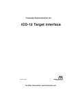


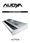

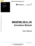

![[DRAFT] DEMO908JL16 User`s Manual](http://vs1.manualzilla.com/store/data/005639706_1-2a84cd2ce2f0b318fdb7aae7896f2a79-150x150.png)