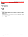
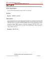
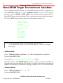
1
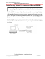
Freescale Semiconductor, Inc.
HI-WAVE
NORAL BDM
Target Interface
© Copyright 1987-1999 HIWARE
For More Information: www.freescale.com
HIWAVE
Freescale Semiconductor, Inc.
Product Manual
Manual Date
HI-WAVE - NORAL BDM
11/99
© Copyright 1987-1999 HIWARE
For More Information: www.freescale.com
HIWAVE
3
Freescale Semiconductor, Inc.
Contents
HC12 NORAL BDM Target Interface. . . . . . . . . . . . . . 5
Overview . . . . . . . . . . . . . . . . . . . . . . . . . . . . . . . . . . . . . . . . . . . . . 5
Introduction . . . . . . . . . . . . . . . . . . . . . . . . . . . . . . . . . . . . . . . . . . . 6
Interfacing Your System and Noral-BDM . . . . . . . . . . . . . . . . . . . . 7
Loading the Noral-BDM Target Component . . . . . . . . . . . . . . . . . . 8
The HI-WAVE Status Bar for the Noral-BDM . . . . . . . . . . . . . . . . . . . . . . . . . . 11
Noral-BDM Target Component Menu Entries. . . . . . . . . . . . . . . . 13
Loading an application . . . . . . . . . . . . . . . . . . . . . . . . . . . . . . . . . . . . . . . . . . . . . 13
Reset . . . . . . . . . . . . . . . . . . . . . . . . . . . . . . . . . . . . . . . . . . . . . . . . . . . . . . . . . . . 13
Communication Specification. . . . . . . . . . . . . . . . . . . . . . . . . . . . . . . . . . . . . . . . 13
MCU Selection . . . . . . . . . . . . . . . . . . . . . . . . . . . . . . . . . . . . . . . . . . . . . . . . . . . 14
MCU Clock Frequency . . . . . . . . . . . . . . . . . . . . . . . . . . . . . . . . . . . . . . . . . . . . . 15
Hardware Breakpoint Configuration. . . . . . . . . . . . . . . . . . . . . . . . . . . . . . . . . . . 16
On-Chip Hardware Breakpoint . . . . . . . . . . . . . . . . . . . . . . . . . . . 17
Disabled mode. . . . . . . . . . . . . . . . . . . . . . . . . . . . . . . . . . . . . . . . . . . . . . . . . . . . 17
Automatic (controlled by debugger) mode . . . . . . . . . . . . . . . . . . . . . . . . . . . . . . 18
User Controlled mode . . . . . . . . . . . . . . . . . . . . . . . . . . . . . . . . . . . . . . . . . . . . . . 19
HOTPLUG Connection . . . . . . . . . . . . . . . . . . . . . . . . . . . . . . . . . 27
Who to "Hotplug" with the Noral-BDM Target Interface? . . . . . . . . . . . . . . . . . 27
Noral-BDM Target Component Commands . . . . . . . . . . . . . . . . . 29
Noral-BDM Target Environment Variables. . . . . . . . . . . . . . . . . . 34
Index . . . . . . . . . . . . . . . . . . . . . . . . . . . . . . . . . . . . . . . . 39
For More Information: www.freescale.com
© Copyright 1987-1999 HIWARE
HIWAVE
4
Freescale Semiconductor, Inc.
For More Information: www.freescale.com
© Copyright 1987-1999 HIWARE
HIWAVE
HC12 NORAL BDM Target Interface
5
Freescale Semiconductor, Inc.
HC12 NORAL BDM Target
Interface
Overview
• The Introduction section introduces the Noral-BDM Target Interface concept.
• The Interfacing Your System and Noral-BDM section gives a small overview on
communication between your host, the Flex BDM interface and supported hardware.
• The Loading the Noral-BDM Target Component section explain how to set the
Noral-BDM target interface within HI-WAVE.
• The Noral-BDM Target Component Menu Entries section describes the different
entries of the Noral-BDM menu.
• The On-Chip Hardware Breakpoint section explains how to use the Hardware
Breakpoint Configuration dialog to set hardware breakpoints and watchpoints.
• The HOTPLUG Connection section explains you how to proceed to hotplug a
stand alone running hardware.
• The Noral-BDM Target Component Commands section lists all Command Line
commands bound to Noral-BDM Target Interface.
• The Noral-BDM Target Environment Variables section lists all PROJECT.INI
and DEFAULT.ENV environment variables bound to the Noral-BDM Target Interface.
For More Information: www.freescale.com
© Copyright 1987-1999 HIWARE
HI-WAVE
6
Freescale Semiconductor, Inc.
Introduction
Introduction
Another advanced feature of HI-WAVE for the embedded system development
world is the ability to load different Framework targets. The Noral-BDM Background Debug Interface is introduced in this document.
The Noral-BDM is an interface developed by Noral and used by HI-WAVE to communicate with an external system also called target system.
With this interface, you can download an executable program from the HI-WAVE
environment to an external target system based on a Motorola MCU which will execute it. You will also have the feedback of the real target system behaviour to HIWAVE.
HI-WAVE will fully supervise and monitor the MCU of the target system i.e. control the CPU execution. You can read and write in internal/external memory (even
when the CPU is running), single-step/run/stop the CPU, set breakpoints in the
code.
Note:
Unconcerned Components As the code is executed by an
external MCU, memory statistics are not available with the Noral-BDM target component. Therefore, Profiling, Coverage analysing and I/O simulation will not work with the Noral-BDM.
For More Information: www.freescale.com
© Copyright 1987-1999 HIWARE
HI-WAVE
HC12 NORAL BDM Target Interface
7
Freescale Semiconductor, Inc.
Interfacing Your System and Noral-BDM
Note: Noral-BDM Structure, Configuration, Connection to the Host, Connection
to the Target, Working Modes are described in Flex Tools User Manual from
Noral.
The Noral-BDM interface is designed around a parallel communication link. It is
supported by any available communication device of your system (PC or SUN).
The communication protocol between the Noral-BDM and your system is fully handled by the BDM Target driver automatically loaded with the Noral-BDM Target
Component. However you can adapt your target system to the Noral-BDM interface.
The Noral-BDM - target system communication is serial. The parallel communication port will be used to communicate between your computer and the Noral-BDM
device box.
For More Information: www.freescale.com
© Copyright 1987-1999 HIWARE
HI-WAVE
8
Loading the Noral-BDM Target Component
Freescale Semiconductor, Inc.
Loading the Noral-BDM Target
Component
Usually the target is set in the PROJECT.INI file, where Target=Noralbdm. If
no target is set in the PROJECT.INI file or if a different target is set, you can load
the BDM driver selecting in the main menu Component | Set Target... as shown
below and choose Noralbdm in the list of proposed targets.
The Noral-BDM target .DLL file is not included in the HI-WAVE base installation.
After a successful target loading, the Target menu item is replaced by Noral-BDM.
The startup command file STARTUP.CMD is executed by HI-WAVE straight after
the Noral-BDM Target Interface has been loaded. This file must be located in the
current project directory and might contain any HI-WAVE or Noral-BDM Target
command to setup the hardware target before loading an application.
Configuration of the MCU Name
In order to initialize the Noral-BDM and to perform some operations, the MCU
type connected to the Noral-BDM must be set correctly.
If no MCU-Id was specified (Please see section Noral-BDM Default Environment)
or the MCU name does not correspond with the expected name, an error-message
pops up and the following dialog appears:
For More Information: www.freescale.com
© Copyright 1987-1999 HIWARE
HI-WAVE
HC12 NORAL BDM Target Interface
9
Freescale Semiconductor, Inc.
Make sure that the MCU name corresponds exact with the name expected from the
Noral-BDM interface, otherwise connection to the Noral-BDM is impossible. MCU
names which are accepted from Noral are:
68HC12B32, 68HC12A4, 68HC12D60, 68HC12DG128, 68HC12DA128
If the expected MCU name is not contained in the MCU-list, press the New... button, to open the following dialog:
Through this dialog, the MCU name can be adapted in such a way that the NoralBDM interface can recognize the used MCU type correctly. If the specified MCU
Id does not exist, a new entry is done in the Mdsemcu.ini file.
Communication Device
In case the MCU name was correct specified an no connection can be established,
an error-message pops up and the following dialog appears:
For More Information: www.freescale.com
© Copyright 1987-1999 HIWARE
HI-WAVE
10
Loading the Noral-BDM Target Component
Freescale Semiconductor, Inc.
Through this dialog, the used communications DLL file (from NORAL) can be
specified. For the standard DLL it is PICLPT.DLL which is also used as default
DLL. By using an alternative DLL it is possible to support remote network interfaces whereby the Noral-BDM unit is connected to a remote PC which is in turn
connected via TCP/IP to the PC running the HI-WAVE.
The LPT port number which the Noral-BDM is connected to must be configured.
The default port used is LPT1. E.g the standard DLL is used and the BDM unit is
connected to LPT1:
PICLPT.DLL,Port=1
For NT installation, the default communication DLL is: PICLPTNT.DLL
Show Protocol
If the Show Protocol box is checked, the communication functions delivered from
Noral Micrologics which are called from the Noral-BDM target component are
reported in the Command Line window. The default state is unchecked.
Note: This feature is used by support personnel from HIWARE.
Clock Configuration
For communication between the Noral-BDM unit and the target system, the clock
For More Information: www.freescale.com
© Copyright 1987-1999 HIWARE
HI-WAVE
HC12 NORAL BDM Target Interface
11
Freescale Semiconductor, Inc.
type of the BDM unit must be set correctly. This is the clock the BDM unit uses to
synchronize with the target BDM. There are different modes possible:
Asynchronous clock: In this mode, the Noral-BDM unit uses its own internal
clock thus running asynchronously with the target. The optional ECLK signal is not
needed. The internal clock must be configured with the BDM baudrate of the target.
ECKL: The Noral-BDM unit uses the ECKL signal of the target, which allows
changes of the BDM clock on the target. In this mode the flying lead ECKL of the
Noral-BDM unit must be connected to the ECKL of the target.
Oscillator: The Noral-BDM unit uses the target oscillator. The target oscillator
must be double the ECLK frequency. The flying lead ECKL of the Noral-BDM unit
must be connected to the oscillator clock of the target.
The BDM clock (for asynchronous mode) and the BDM clock mode can be set
through the environment variables MCUCLOCKSPEED and MCUCLOCKTYPE
and through menu command Noral-BDM | Set MCU speed...
(Please see section Noral-BDM Default Environment and Noral-BDM Target Component Menu Entries). The asynchronous clock is set as default mode and the
default BDM baud rate is set to 6 MHz.
The flying leads MODA and MODB are needed to control the processor’s start-up
mode. This prevents that the MCU begin normal execution until it is brought under
control by entering BDM mode.
Flash Programming
The HI-WAVE Noral-BDM interface has a build-in FLASH Programming interface to program onchip FLASH EEPROM modules, that you can open when choosing the Flash... entry in the Noral-BDM menu. This FLASH Programming utility
must be licensed to work without size limitation. Please see the HI-WAVE Flash
Programming manual to know more about the usage of this interface.
Note: It is necessary to switch the Flash Programming voltage on with the
SETVPP command before loading an application in Flash.
The HI-WAVE Status Bar for the Noral-BDM
For More Information: www.freescale.com
© Copyright 1987-1999 HIWARE
HI-WAVE
12
Loading the Noral-BDM Target Component
Freescale Semiconductor, Inc.
When the Noral-BDM Target Component has been loaded, specific information are
given in the HI-WAVE status bar. From the left to the right are displayed the BDM
clock speed in case the asynchronous clock is used, the voltage of the target, the
target CPU and the Noral-BDM status.
For More Information: www.freescale.com
© Copyright 1987-1999 HIWARE
HI-WAVE
HC12 NORAL BDM Target Interface
13
Freescale Semiconductor, Inc.
Noral-BDM Target Component Menu
Entries
Loading an application
Choose Noral-BDM | Load... to load the application to debug, i.e. a .ABS file.
Reset
The Command Noral-BDM | Reset executes the reset command file RESET.CMD
file and resets the target system processor.
Communication Specification
Select entry Noral-BDM | Connect... to display the dialog box shown below.
If the connection to Noral-BDM unit is ok, the menu entry Connect... changes to
Communication... and only the Show Protocol box can be modified.
Communication Device Through this box, the used communications DLL file
and the communication port can be specified. For the standard DLL it is
PICLPT.DLL and for the LPT1 port of the host computer it is PORT=1.
For More Information: www.freescale.com
© Copyright 1987-1999 HIWARE
HI-WAVE
14
Noral-BDM Target Component Menu Entries
Freescale Semiconductor, Inc.
Show Protocol If the Show Protocol box is checked, the communication functions delivered from Noral Micrologics which are called from the Noral-BDM target component are reported in the Command Line window.
Note: This feature is used by support personnel from HIWARE.
For more details please see section Communication Device of chapter Loading the
Noral-BDM target component.
Note: The communication device and the baud rate saved through this dialog
override environment variables SHOWPROT and COMDEV of the
DEFAULT.ENV file.
HotPlug connection If the HotPlug connection is checked, the debugger enters
the HotPlug connection procedure described at section HOTPLUG Connection.
This checkbox can be checked only checked at Noralbdm target component loading.
MCU Selection
Choose Noral-BDM | Set MCU Type... to open this dialog.
This dialog allows you to select the MCU currently used. There are two drop list
For More Information: www.freescale.com
© Copyright 1987-1999 HIWARE
HI-WAVE
HC12 NORAL BDM Target Interface
15
Freescale Semiconductor, Inc.
Combo controls. They show the currently selected MCU name and MCU-ID.
The information will be taken from the file MDSEMCU.INI. If a specific MCU is
not found in this file or the MCU name corresponds not exact with the name
expected from the Noral-BDM interface, use the New button to open the dialog
shown below:
Through this dialog the MCU name and the MCU-Id can be changed.
For details please see section Configuration of the MCU Name.
Note: The MCU-Id saved through this dialog overrides the environment variable
MCUID of the DEFAULT.ENV file.
MCU Clock Frequency
Choose Noral-BDM | Set MCU Speed... to open this dialog. Sets the Noral-BDM
unit clock type. This is the clock the BDM unit uses to synchronize with the target
BDM.
For communication between the Noral-BDM unit and the target system, the BDM
clock must be set correctly. There are different modes possible:
Asynchronous clock: In this mode, the Noral-BDM unit uses its own internal
For More Information: www.freescale.com
© Copyright 1987-1999 HIWARE
HI-WAVE
16
Noral-BDM Target Component Menu Entries
Freescale Semiconductor, Inc.
clock thus running asynchronously with the target. The optional ECLK signal is not
needed. The internal clock must be configured with the BDM baudrate of the target.
ECKL: The Noral-BDM unit uses the ECKL signal of the target, which allows
changes of the BDM clock on the target. In this mode the flying lead ECKL of the
Noral-BDM unit must be connected to the ECKL of the target.
Oscillator: The Noral-BDM unit uses the target oscillator. The target oscillator
must be double the ECLK frequency. The flying lead ECKL of the Noral-BDM unit
must be connected to the oscillator clock of the target.
Note: The BDM Clock and the BDM Clock Mode saved through this dialog overrides the environment variable MCUCLOCKSPEED and MCUCLOCKTYPE of the DEFAULT.ENV file.
Hardware Breakpoint Configuration
Choose Noral-BDM | Set Hardware BP... to open this dialog.
This dialog allows to set up the hardware breakpoint module of the used HC12
derivative.
For details about Hardware Breakpoint Configuration dialog please see section Onchip Hardware Breakpoint.
.
Note: This feature is available only if the HC12 derivative connected to the debugger through the Noral-BDM has an hardware breakpoint module. Check
your MCU documentation.
For More Information: www.freescale.com
© Copyright 1987-1999 HIWARE
HI-WAVE
HC12 NORAL BDM Target Interface
17
Freescale Semiconductor, Inc.
On-Chip Hardware Breakpoint
On some HC12 derivatives, an on-chip hardware breakpoint module can be used to
set breakpoints and watchpoint. To invoke this module, it is necessary to set up the
debugger to use this on-chip hardware breakpoint module.
This can be done using the Hardware Breakpoint Configuration dialog.
Select Noral-BDM | Set Hardware BP... menu entry. The Hardware Breakpoint
Configuration dialog is displayed.
The Mode combo box allows to select between three different modes: Disabled,
Automatic (controlled by debugger) and User Controlled.
Disabled mode
This is the default mode for HI-WAVE. When the hardware breakpoint module is
disabled, it is not possible to set breakpoint in Flash or in EEPROM. It is also not
For More Information: www.freescale.com
© Copyright 1987-1999 HIWARE
HI-WAVE
18
On-Chip Hardware Breakpoint
Freescale Semiconductor, Inc.
possible to set any watchpoint, even if the application is loaded in RAM.
Note: Some actions like “stepping over” or “stepping out” use one internal
breakpoint and therefore can not be used when debugging in non volatile
memory if the hardware breakpoint module is disabled.
Automatic (controlled by debugger) mode
If the Automatic (controlled by debugger) mode is selected, you have the possibility
to set up to two breakpoints in Non Volatile Memory (or one watchpoint).
In order to set the debugger correctly, the address of the hardware breakpoint module must be set in the Module base address edit box.
The Module base address is typically 0x20 for the M68HC912B32,
M68HC912D60 and M68HC912DG128.
For other derivatives, please refers to Motorola’s documentation.
When those settings are done, any breakpoint which is set in Non Volatile Memory
is considered by the debugger as an Hardware Breakpoint.
If your application is loaded in RAM, breakpoints are software breakpoints. In this
case the Hardware Breakpoint module gives you the possibility to debug with
breakpoints and watchpoint (only one watchpoint is available).
For More Information: www.freescale.com
© Copyright 1987-1999 HIWARE
HI-WAVE
HC12 NORAL BDM Target Interface
19
Freescale Semiconductor, Inc.
.
Note: In Automatic mode, the HC12 hardware breakpoint module allows only two
breakpoints (or one watchpoint) at the same time. If you are debugging your
code in FLASH, you can not set more than two breakpoints or one watchpoint.
Note: Some actions like “stepping over” or “stepping out” use one internal
breakpoint and therefore reduce your amount of hardware breakpoint to
one.
Note: The M68HC812A4 does not have any Hardware Breakpoint module.
Note: The M68HC912DG128 hardware breakpoint module is not always able to
handle correctly breakpoints on banked code, as address matching is only
done on 2 bytes, regardless the PPAGE.
User Controlled mode
This mode allows you to fully set up the breakpoint module according to
Motorola’s documentation.
The following registers can be modified:
1. BRKCT0: Breakpoint Control Register 0
2. BRKCT1: Breakpoint Control Register 1
3. BRKA: Breakpoint Address Register
4. BRKD: Breakpoint Data Register
For more information about those registers, please refers to your MCU reference
manual section Breakpoints of the Background Debug Mode (Development Support
part of the manual).
.
Note: When a hardware breakpoint or watchpoint is set in User controlled mode,
the message displayed in the status bar when the breakpoint or watchpoint
is reached is ILLEGAL_BP.
Note: If the control point set is a breakpoint, it is needed to perform a single step
before running again the target otherwise the target will endlessly break on
the same address bus access.
For More Information: www.freescale.com
© Copyright 1987-1999 HIWARE
HI-WAVE
20
On-Chip Hardware Breakpoint
Freescale Semiconductor, Inc.
Setting hardware breakpoints in user controlled mode (BDM
- Dual Address Mode)
Setting one hardware breakpoint in user controlled mode (BDM - Dual
Address Mode)
To set an hardware breakpoint in user controlled mode, perform the following
steps:
1. Open the Hardware Breakpoint Configuration dialog.
2. Select the User Controlled mode in the Mode list box.
3. Specify the address of the breakpoint module in Module base address edit box.
4. Set the address of the breakpoint in the BRKA register.
5. In the BRKCT0 group, select the BDM - Dual address Mode for the breakpoint
module.
6. The BKPM bit must be set so that the breakpoint module breaks if the match is on
an instruction that will be executed.
7. The BK0ALE bit is set so that the full 16-bit value in BRKA is used to compare
the address bus.
In the following bitmap, one hardware breakpoint is set at address 0xC080:
8. Click Ok to close the Hardware Breakpoint Configuration dialog.
9. Run the target. If the breakpoint can be reached, the debugger is stopped and
ILLEGAL_BP is displayed in the status bar.
10.To run the target again, it is needed to first perform an assembly or single step
otherwise the same breakpoint is reached again and again.
For More Information: www.freescale.com
© Copyright 1987-1999 HIWARE
HI-WAVE
HC12 NORAL BDM Target Interface
21
Freescale Semiconductor, Inc.
Setting one second hardware breakpoint in user controlled mode
(BDM - Dual Address Mode)
To set one second hardware breakpoint in User Controlled mode, perform the following steps:
1. Set the address of the second breakpoint in the BRKD register.
2. In BRKCT0, the BK1ALE bit is set so that the full 16-bit value in BRKD is used to
compare the address bus.
3. In BRKCT1, the BKDBE bit is set to enable the comparison of BRKD with the
address bus.
In the following bitmap, two hardware breakpoint are set at address 0xC080 and
0xC08F:
4. Click Ok to close the Hardware Breakpoint Configuration dialog.
5. Run the target. If the breakpoints can be reached, the debugger is stopped and
ILLEGAL_BP is displayed in the status bar. Do not forget to perform a single
step before running the target otherwise the target will stop again on the same
breakpoint.
Setting watchpoints in user controlled mode (BDM - Dual
Address Mode)
Setting one watchpoint in user controlled mode (BDM - Dual Address
Mode)
To set a watchpoint in User Controlled mode, perform the following steps:
1. Open the Hardware Breakpoint Configuration dialog.
For More Information: www.freescale.com
© Copyright 1987-1999 HIWARE
HI-WAVE
22
On-Chip Hardware Breakpoint
Freescale Semiconductor, Inc.
2. Select the User Controlled mode in the Mode list box.
3. Specify the address of the breakpoint module in Module base address edit box.
4. Set the address of the watchpoint in the BRKA register.
5. In the BRKCT0 group, select the BDM - Dual address Mode for the breakpoint
module.
6. The BK0ALE bit is set so that the full 16-bit value in BRKA is used to compare
the address bus.
In the following bitmap, one read/write access watchpoint is set at address 0x2000
(the access size for this watchpoints is 1 byte):
7. Click Ok to close the Hardware Breakpoint Configuration dialog.
8. Run the target. If the watchpoint can be reached, the debugger is stopped and
ILLEGAL_BP is displayed in the status bar.
Note: A two bytes access size watchpoint can be set up by using two contiguous
one byte access size watchpoint.
Setting one second watchpoint in user controlled mode (BDM - Dual
Address Mode)
To set a second watchpoint in User Controlled mode, perform the following steps:
1. Set the address of the second watchpoint in the BRKD register.
2. In BRKCT0, the BK1ALE bit is set so that the full 16-bit value in BRKD is used to
compare the address bus.
3. In BRKCT1, the BKDBE bit is set to enable the comparison of BRKD with the
address bus.
In the following bitmap, two read/write access watchpoints are set at address
For More Information: www.freescale.com
© Copyright 1987-1999 HIWARE
HI-WAVE
HC12 NORAL BDM Target Interface
23
Freescale Semiconductor, Inc.
0x2000 and 0x2002 (the access size for those watchpoints is 1 byte):
4. Click Ok to close the Hardware Breakpoint Configuration dialog.
5. Run the target. If the watchpoints can be reached, the debugger is stopped and
ILLEGAL_BP is displayed in the status bar.
Note: A two bytes access size watchpoint can be set up by using two contiguous
one byte access size watchpoint.
Controlling the kind of access of the two watchpoints in user controlled mode (BDM - Dual Address Mode)
The breakpoint module can be set up so that a break occurs on a read, a write or a
read/write data access.
For each watchpoint, two bytes are defined in the BRKCT1 register to set up the
kind of access:
• BK0RWE and BK0RW are use to set up the kind of access on the address specified in the BRKA register.
• BK1RWE and BK1RW are use to set up the kind of access on the address specified in the BRKD register.
The following table shows how to define the values in those registers to select the
correct access kind:
READ/WRITE
WRITE
READ
BKxRWE
BKxRW
0
1
1
0
0
1
For More Information: www.freescale.com
© Copyright 1987-1999 HIWARE
HI-WAVE
24
On-Chip Hardware Breakpoint
Freescale Semiconductor, Inc.
The following example show how to set up the READ/WRITE (default) watchpoints
set in the previous section to be READ or WRITE watchpoints.
1. The BKxRWE bit of BRKCT1 register must be set for both watchpoints so that the
access kind is checked.
2. Leave the BK0RW bits reset in BRKCT1. The hardware breakpoint modules will
break on a WRITE access for the address in BRKA.
3. Set the BK1RW bits in BRKCT1. The hardware breakpoint modules will break on
a READ access for the address in BRKD.
In the following bitmap, a write access watchpoint is set at address 0x2000 and a
read access watchpoint is set at address 0x2002 (the access size for those watchpoint is 1 byte):
4. Click Ok to close the Hardware Breakpoint Configuration dialog.
5. Run the target. If the watchpoints can be reached, the debugger is stopped and
ILLEGAL_BP is displayed in the status bar. The debugger stops on read access at
the address in BRKA and on write access at the address in BRKD.
.
Note: If a two bytes access size watchpoint has been set up by using two contiguous one byte access size watchpoint, the settings for the access kind should
be the same for the registers BRKA and BRKD.
Setting one conditional watchpoint in user controlled mode
(BDM - Full Breakpoint Mode)
To set a conditional watchpoint in User Controlled mode, perform the following
steps:
For More Information: www.freescale.com
© Copyright 1987-1999 HIWARE
HI-WAVE
HC12 NORAL BDM Target Interface
25
Freescale Semiconductor, Inc.
1. Open the Hardware Breakpoint Configuration dialog.
2. Select the User Controlled mode in the Mode list box.
3. Specify the address of the breakpoint module in Module base address edit box.
4. Set the address of the watchpoint in the BRKA register.
5. Set the value to match on break in the BRKD register. This value is an hexadecimal value.
6. In the BRKCT0 group, select the BDM - Full Breakpoint Mode for the breakpoint
module.
7. The BK0ALE bit is set so that the full 16-bit value in BRKA is used to compare
the address bus.
8. In the BRKCT1 group, the BKDBE bit is set to enable the BRKD register.
In the following bitmap, a conditional read/write access watchpoint is set at address
0x2002, the debugger will stop when the 16-bit value at address 0x2002 is equal
to 0x0005:
The access kind can also be specified using the BK0RWE and BK0RW bit of the
BRKCT1 group:
READ/WRITE
WRITE
READ
BK0RWE
BK0RW
0
1
1
0
0
1
In the following bitmap, a conditional write access watchpoint is set at address
0x2002, the debugger will stop when the 16-bit value at address 0x2002 is equal
to 0x0005 and is read:
For More Information: www.freescale.com
© Copyright 1987-1999 HIWARE
HI-WAVE
26
On-Chip Hardware Breakpoint
Freescale Semiconductor, Inc.
In the following bitmap, a conditional write access watchpoint is set at address
0x2002, the debugger will stop when 0x0005 is written at address 0x2002 (16bit value):
For More Information: www.freescale.com
© Copyright 1987-1999 HIWARE
HI-WAVE
HC12 NORAL BDM Target Interface
27
Freescale Semiconductor, Inc.
HOTPLUG Connection
The Flex BDM interface HOTPLUG feature gives you the possibility to connect to
a stand alone running hardware equipped with a BDM connector and therefore to
trace the current running code.
Who to "Hotplug" with the Noral-BDM Target Interface?
1. IMPORTANT: Your STARTUP.CMD and RESET.CMD should not execute any
hardware access command, like WB (write byte) commands. If this kind of command exists, put these commands into comments with "//".
2. Power supply your Flex BDM interface. Do NOT connect the BDM connect
now!
3. Start the HI-WAVE debugger and load the Noralbdm target. After a short while,
the dialog below is displayed:
4. After checking the HotPlug connection checkbox, click the Connect button. The
HOTPLUG Connection message informs you that you are about to hotplug.
From this point, you can cancel the operation clicking No or go on clicking Yes.
5. When clicking Yes, the Flex BDM interface connector is "de-activated", like if
each wire was in high impedance level. The dialog below is displayed.
For More Information: www.freescale.com
© Copyright 1987-1999 HIWARE
HI-WAVE
28
Freescale Semiconductor, Inc.
HOTPLUG Connection
6. Now you can connect the Flex BDM connector to your hardware BDM connector. Once done, click the Ok button.
7. The debugger turns to Running status automatically. To found out where is currently the running program, you need stop the debugger.
8. Then choosing Noral-BDM | Load... menu, you can load with "Load Symbols
only" Load option the running program in the debugger as show below to display
and trace the original Source code.
Note: Do NOT load the program Code otherwise the PC will be modified. Load
with "Load Symbols only" Load option.
For More Information: www.freescale.com
© Copyright 1987-1999 HIWARE
HI-WAVE
HC12 NORAL BDM Target Interface
29
Freescale Semiconductor, Inc.
Noral-BDM Target Component Commands
The following commands can be used in any command file, e.g. STARTUP.CMD
file, or typed in the Command Line component. The startup command file STARTUP.CMD is executed by HI-WAVE straight after the Noral-BDM Target Interface
has been loaded. This file must be located in the current project directory. You can
use any HI-WAVE command in this file and take advantage of the wide set of commands introduced in the HI-WAVE manual to setup the target hardware before loading any application.
The ICD-12 Target Interface specific commands are:
BANKWINDOW
PROTOCOL
RESET
SETVPP
Those commands can be entered in the STARTUP.CMD file or in the Command
Line component of HI-WAVE.
BANKWINDOW
–––––––––––––––––––––––––
Short Description
specify a banked memory area
Syntax
BANKWINDOW (PPAGE|DPAGE|EPAGE) <range> <reg. address>
Description
With the command Bankwindow, it is possible to set up the debugger to work in
banked memory model.
To define a banked memory area, the range of memory in the page and the address
of the corresponding page register must be defined. Three different page registers
can be specified: DPAGE, EPAGE and PPAGE. These registers are displayed in the
register component.
For More Information: www.freescale.com
© Copyright 1987-1999 HIWARE
HI-WAVE
30
Noral-BDM Target Component Commands
Freescale Semiconductor, Inc.
Example BANKWINDOW PPAGE 0x8000..0xBFFF 0xFF
This command allows to use the banked memory model in HI-WAVE using the
M68HC12DG128.
This commands means the PPAGE register located at address 0xFF must be used to
build the PC address when the code is located in banked memory area, from
0x8000 to 0xBFFF.
The PPAGE register (located at address 0xFF) will be displayed in the register
component.
Example
BANKWINDOW PPAGE 0x8000..0xBFFF 0x35
BANKWINDOW DPAGE 0x7000..0x7FFF 0x34
BANKWINDOW EPAGE 0x0400..0x07FF 0x36
These 3 consecutive commands set the Noral-BDM interface to use the banked
memory model with an HC12A4 derivative wired with codepage, datapage and
extrapage.
For More Information: www.freescale.com
© Copyright 1987-1999 HIWARE
HI-WAVE
HC12 NORAL BDM Target Interface
31
Freescale Semiconductor, Inc.
PROTOCOL
–––––––––––––––––––––––––
Short Description
switches on/off the Show Protocol functionality
Syntax
PROTOCOL ON|OFF
Description
If this command is used, all the messages sent to and received from the ICD-12
interface are reported in the Command Line window of HI-WAVE.
Example PROTOCOL ON
Note: The Show Protocol is a useful debugging feature if there is a communication
problem.
For More Information: www.freescale.com
© Copyright 1987-1999 HIWARE
HI-WAVE
32
Noral-BDM Target Component Commands
Freescale Semiconductor, Inc.
RESET
–––––––––––––––––––––––––
Short Description
resets of the target board
Syntax
RESET
Description
With this command it is possible to reset the target from the Command Line component of HI-WAVE.
The target board is reset and the reset vector is read in the target memory from the
vector table (address 0xFFFE).
Example RESET
For More Information: www.freescale.com
© Copyright 1987-1999 HIWARE
HI-WAVE
HC12 NORAL BDM Target Interface
33
Freescale Semiconductor, Inc.
SETVPP
–––––––––––––––––––––––––
Short Description
sets on/off the programming voltage of the Flex interface.
Syntax
Syntax: SETVPP ON|OFF
Description
This command let your set the programming voltage on to program onchip FLASH
EEPROMs with the FLASH programming (NVMC) interface. When the command
“SETVPP ON” is executed, the FLEX module delivers the programming voltage
through its “Berg” BDM connector. When the command “SETVPP OFF” is executed, the FLEX module delivers no more the programming voltage through its
“Berg” BDM connector.
Example SETVPP ON
For More Information: www.freescale.com
© Copyright 1987-1999 HIWARE
HI-WAVE
34
Noral-BDM Target Environment Variables
Freescale Semiconductor, Inc.
Noral-BDM Target Environment Variables
All environment variables used by the Noral-BDM Target Interface component are
in the PROJECT.INI file or in the DEFAULT.ENV file of your current project
directory, section [NORAL FLEX BDM]. All variables match settings from the
Noral-BDM Target Interface dialogs. They usually must be set within these dialogs.
The Noral-BDM Target Interface specific environment variables are:
BPModuleAdr
BPModuleMode
COMDEV
MCUClockSpeed
MCUClockType
MCUId
REG_BRKA
REG_BRKB
REG_BRKCT0
REG_BRKCT1
SHOWPROT
Note: Please see the HI-WAVE Flash Programming manual for
NV_PARAMETER_FILE, NV_SAVE_WSP and NV_AUTO_ID variables
description.
• BPModuleAdr
Syntax: BPModuleAdr=<address of the breakpoint module>
Location: PROJECT.INI
Associated to: Hardware Breakpoint Configuration dialog
Short Description: The BPModuleAdr variable is used to specify the address of
the hardware breakpoint module. This address is needed if the hardware breakpoint
module is in Automatic (controlled by debugger) mode or in User Controlled mode.
• BPModuleMode
Syntax: BPModuleMode= 0 | 1 | 2
Location: PROJECT.INI
For More Information: www.freescale.com
© Copyright 1987-1999 HIWARE
HI-WAVE
HC12 NORAL BDM Target Interface
35
Freescale Semiconductor, Inc.
Associated to: Hardware Breakpoint Configuration dialog
Short Description: The BPModuleMode variable is used to specify the hardware
breakpoint module mode:
• BPModuleMode=0 the hardware breakpoint module is disabled.
• BPModuleMode=1 the hardware breakpoint module is in Automatic (controlled by debugger) mode. In this case, variable BPModuleAdr is used to
specify the address of the breakpoint module.
• BPModuleMode=2 the hardware breakpoint module is in User Controlled
mode. In this case, the variable BPModuleAdr is used to specify the address of
the breakpoint module, REG_BRKCT0, REG_BRKCT1, REG_BRKA and
REG_BRKB are used to store the values set in registers BRKA, BRKB, BRKCT0
and BRKCT1 of the hardware breakpoint module.
• COMDEV
Syntax: COMDEV=<Noral parallel port communication DLL filename>,
PORT=<LPT port number>
Example COMDEV=PICLPT.DLL,PORT=1
Location: PROJECT.INI
Associated to: Communication Device Specification dialog
Short Description: The communication DLL file and port to be used on the host
computer can be specified using the variable COMDEV.
• MCUClockSpeed
Syntax: MCUClockSpeed=< X-tal value(Hz)/2 >
Location: PROJECT.INI
Associated to: Set MCU Speed dialog
Short Description: The target MCU X-tal frequency / 2.
• MCUClockType
Syntax: MCUCLOCKTYPE=ASYNC|ECLK|OSC/2
Location: PROJECT.INI
Associated to: Set MCU Speed dialog
Short Description: The BDM clock mode can be set up through this environment
variable. For details please see section Clock Configuration. The asynchronous
For More Information: www.freescale.com
© Copyright 1987-1999 HIWARE
HI-WAVE
36
Noral-BDM Target Environment Variables
Freescale Semiconductor, Inc.
mode is set as default mode. This environment variable will be overwritten if the
BDM clock mode is changed in a later debug session.
• MCUID
Syntax: MCUID=<MCU-ID of the connected derivative>
Location: PROJECT.INI
Associated to: MCU Selection dialog
Short Description: The MCUID variable is used to store the MCU-ID of the derivative connected to the Flex interface.
Each MCU has its own MCU-ID which is assigned by Motorola.
• REG_BRKA
Syntax: REG_BRKA=<value in the BRKA register>
Location: PROJECT.INI
Associated to: Hardware Breakpoint Configuration dialog
Short Description: The REG_BRKA variable is used to store the value of the BRKA
register of the breakpoint module when it is used in User Controlled mode.
For more details about the BRKA (Breakpoint Address Register) register, please
check your MCU documentation from Motorola.
• REG_BRKB
Syntax: REG_BRKB=<value in the BRKB register>
Location: PROJECT.INI
Associated to: Hardware Breakpoint Configuration dialog
Short Description: The REG_BRKB variable is used to store the value of the BRKB
register of the breakpoint module when it is used in User Controlled mode.
For more details about the BRKB (Breakpoint Data Register) register, please check
your MCU documentation from Motorola.
• REG_BRKCT0
Syntax: REG_BRKCT0=<value in the BRKCT0 register>
Location: PROJECT.INI
Associated to: Hardware Breakpoint Configuration dialog
For More Information: www.freescale.com
© Copyright 1987-1999 HIWARE
HI-WAVE
HC12 NORAL BDM Target Interface
37
Freescale Semiconductor, Inc.
Short Description: The REG_BRKCT0 variable is used to store the value of the
BRKCT0 register of the breakpoint module when it is used in User Controlled
mode.
For more details about the BRKCT0 (Breakpoint Control Register 0) register, please
check your MCU documentation from Motorola.
• REG_BRKCT1
Syntax: REG_BRKCT1=<value in the BRKCT1 register>
Location: PROJECT.INI
Associated to: Hardware Breakpoint Configuration dialog
Short Description: The REG_BRKCT1 variable is used to store the value of the
BRKCT1 register of the breakpoint module when it is used in User Controlled
mode.
For more details about the BRKCT1 (Breakpoint Control Register 1) register, please
check your MCU documentation from Motorola.
• SHOWPROT
Syntax: SHOWPROT=1|0
Location: PROJECT.INI
Associated to: Communication Device Specification dialog
Short Description: If the Show Protocol is used, all the commands and responses
sent and received are reported in the Command Line component of HI-WAVE.
If the variable is set to 1, Show Protocol is activated.
For More Information: www.freescale.com
© Copyright 1987-1999 HIWARE
HI-WAVE
38
Noral-BDM Target Environment Variables
Freescale Semiconductor, Inc.
For More Information: www.freescale.com
© Copyright 1987-1999 HIWARE
HI-WAVE
Index
39
Freescale Semiconductor, Inc.
Index
D
DEFAULT.ENV 14, 15, 16, 34
Dual Address Mode 22
E
Numerics
ECKL 16
ECKL signal 11
Environment Variables 34
68HC12A4 9
68HC12B32 9
68HC12D60 9
68HC12DA128 9
68HC12DG128 9
F
FLASH 11
FLASH Programming 11
A
Asynchronous 15
Asynchronous clock 11
Automatic Hardware Breakpoint 18
B
BANKWINDOW 29
BDM connector 33
Berg BDM connector 33
BK0ALE 20, 22
BK0RW 23
BK0RWE 23
BK1ALE 21, 22
BK1RW 23
BK1RWE 23
BKDBE 21, 22
BKPM 20
BPModuleAdr 34
BPModuleMode 34
Breakpoint 16, 18, 19
Breakpoints 17
BRKA 19, 20
BRKCT0 19, 20, 21, 22, 22
BRKCT1 19, 21, 22
BRKD 19, 21, 22, 22
H
Hardware Breakpoint 16, 17
Hardware Breakpoint Configuration 17
Hardware breakpoint configuration 16
Hardware Breakpoint module
Automatic (controlled by debugger mode)
mode 18
Disabled mode 17
User controlled mode 19
Hardware Breakpoints
conditional watchpoint in user controlled
mode 24
hardware breakpoints in user controlled
mode 20
watchpoints in user controlled mode 21
HotPlug 14
HotPlug connection 14
Hotplug Connection 27
L
Loading an application 13
LPT port 10
M
C
Clock 15
COMDEV 14, 35
Communication 7, 13
Communication port 10
M68HC812A4 19
M68HC912B32 18
M68HC912D60 18
M68HC912DG128 18, 19
MCU Clock Frequency 15
MCU Name 8
For More Information: www.freescale.com
© Copyright 1987-1999 HIWARE
HIWAVE
40
MCU selection 14, 15
MCU Speed 15
MCU Type 14
MCUCLOCKSPEED 16
MCUClockSpeed 35
MCUCLOCKTYPE 16
MCUClockType 35
MCUID 15, 36
MCUId 8
MCUid 15
MDSEMCU.INI 15
Mdsemcu.ini file 9
Module base address 18
Freescale Semiconductor, Inc.
S
Serial communication 7
SETVPP 11, 33
Show Protocol 10
SHOWPROT 14, 37
STARTUP.CMD 8, 27, 29, 29, 29
Statistics 6
Status bar 12
V
Variables 34
Voltage 33
Voltage for flash programming 11
N
NORAL FLEX BDM section 34
Noral-BDM 7
Interface 7
Interfacing 7
Noralbdm 8
W
Watchpoint 17, 21, 22
O
Oscillator 16
Oscillator clock 11
P
Parallel port 10
PICLPT.DLL 10, 13
PICLPTNT.DLL 10
PORT 13
Port 10
Programming voltage 11, 33
PROJECT.INI 8, 34
PROTOCOL 31
Protocol 10, 14
R
REG_BRKA 36
REG_BRKB 36
REG_BRKCT0 36
REG_BRKCT1 37
RESET 32
RESET.CMD 27
For More Information: www.freescale.com
© Copyright 1987-1999 HIWARE
HIWAVE