1
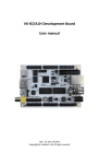
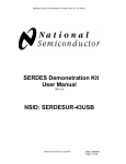
DS90CR485/486 Evaluation Kit User Manual
Rev. 1.01
DS90CR485/486
48-bit, 66 – 133 MHz
Channel Link SerDes Chipset
Evaluation Kit User Manual
Part Number: CLINK3V48BT-133
January 2005
PC and Networking Group
National Semiconductor Corporation
Document Revision 1.01
1 of 32
DS90CR485/486 Evaluation Kit User Manual
Rev. 1.01
Table of Contents
Introduction......................................................................................... 3
Introduction...................................................................................... 4
Evaluation Board Features.............................................................. 4
Contents of the Evaluation Kit ......................................................... 4
Applications ........................................................................................ 5
Getting Started ................................................................................... 7
Setup ............................................................................................... 8
Board Configuration ........................................................................... 9
CLINK3V48BT-133 Evaluation Board Layout Silkscreen .............. 10
Power Connection ......................................................................... 11
Transmitter CLKIN Input Clock...................................................... 12
Default Switch & Jumper Configuration......................................... 13
Alternative Switch & Jumper Configurations ................................. 15
Power Down mode ........................................................................ 15
Cable Deskew ............................................................................... 16
DS_OPT ........................................................................................ 17
Transmitter PRBS Generator Mode .............................................. 19
LVDS Cable Sense (TSEN) Status Flag ....................................... 19
Pin & Signal Assignments ................................................................ 20
IDC Connector............................................................................... 21
MDR Connector............................................................................. 22
Probing LVDS Signals................................................................... 22
Switches ........................................................................................ 23
Jumpers......................................................................................... 23
On-Board Termination Resistors ...................................................... 24
Transmitter LVCMOS/LVTTL Data Input Termination Resistors... 25
Receiver LVDS Input Termination ................................................. 26
Optional Receiver LVCMOS/LVTTL Output Termination Resistors
(Unpopulated)................................................................................ 27
Troubleshooting................................................................................ 28
Troubleshooting............................................................................. 29
Trouble shooting chart:.................................................................. 29
Additional Information....................................................................... 30
Other Resources .............................................................................. 32
2 of 32
DS90CR485/486 Evaluation Kit User Manual
Rev. 1.01
Introduction
3 of 32
DS90CR485/486 Evaluation Kit User Manual
Rev. 1.01
Introduction
The National Semiconductor CLINK3V48BT-133 evaluation kit demonstrates the
performance of the DS90CR485/485 48-bit, 66 – 133 MHz Channel Link SerDes
chipset.
The printed circuit board (PCB) is optimized for the high-speed operation. The
LVCMOS/LVTTL parallel bus trace impedance is 50 Ohms and LVDS differential
impedance is 100 Ohms. Both LVCMOS/LVTTL and LVDS buses have matched
trace lengths for low signal-to-signal skew.
The transmitter serializes 24 LVCMOS/LVTTL double edge inputs (48 bits data
latched in per clock cycle) onto 8 Low Voltage Differential Signaling (LVDS)
streams. A phase-locked clock is also transmitted in parallel with the data
streams over a 9th LVDS pair. The receiver converts the 8 LVDS data streams
plus clock back to 48 LVCMOS/LVTTL data bits plus clock.
This evaluation kit can be used to test and verify the following:
▪ Data serialization and deserialization over backplanes or cable
▪ Bit error rate testing (BERT)
▪ Eye pattern signal quality
▪ Transmitter adjustable LVDS output pre-emphasis
▪ DC balance mode
▪ Transmitter cable detector
▪ Cable deskew function
▪ Interoperability with National’s 112 MHz DS90CR481/482/482/484 chips
(112 MHz CLINK3V48BT-112 evaluation kit required)
Evaluation Board Features
▪
▪
▪
▪
▪
National Semiconductor’s 48-bit, 66 – 133 MHz DS90CR485/486 Channel
Link serializer/deserializer
On-board selectable 66MHz and 133MHz oscillators
Provision for external clock source
Configuration controls for pre-emphasis, DC balance, cable deskew,
power-down, internal pattern generator and pattern select
3M MDR cable and connectors
Contents of the Evaluation Kit
▪
▪
▪
▪
CLINK3V485/486 PCB with the DS90CR485VS Transmitter and the
DS90CR486VS Receiver
One 2-meter 3M MDR LVDS cable interface
Evaluation Kit Documentation (this manual)
DS90CR485/486 Datasheet
4 of 32
DS90CR485/486 Evaluation Kit User Manual
Rev. 1.01
Applications
5 of 32
DS90CR485/486 Evaluation Kit User Manual
Rev. 1.01
8
/
8
/
8
/
8
6.384Gbps
5.38Gbps
/
CLOCK IN
IN
CLOCK
(66 – 133MHz)
(33 - 112MHz)
PLL
8
LVDSCLOCK
CLOCK
LVDS
(66 – 133MHz)
(33
to 112MHz)
POWERDOWN
/
8
/
8
/
8
/
8
/
8
/
PLL
CMOS/TTL Outputs
/
DC BALANCE
8
TTL PARALLEL - TO - LVDS
/
DS90CR486
DS90CR484
LVDS - TO - TTL PARALLEL
CMOS/TTL Inputs
8
LVDS
LVDS
DATA
DATA
396
– 798
198
- 672
Mbps
Mbps
per channel
per channel
DC BALANCE DECODE & DESKEW
DS90CR485
DS90CR483
CLOCK OUT
OUT
CLOCK
(66- –112MHz)
133MHz)
(33
POWERDOWN
Channel Link Application
The diagram above illustrates the use of the Chipset (Tx/Rx). This chipset is able
to transmit 48 bits of TTL/CMOS data using eight LVDS channels at the speed of
6.384Gbps.
Please refer to datasheet for information on Chipsets
6 of 32
DS90CR485/486 Evaluation Kit User Manual
Rev. 1.01
Getting Started
7 of 32
DS90CR485/486 Evaluation Kit User Manual
Rev. 1.01
Setup
The CLINK3V48BT-133 evaluation board is delivered ready to run with
configuration switches and jumpers set to their default positions. To start using
the evaluation kit, follow these steps:
1) Connect one end of the D26-1 MDR cable to the transmitter output
connector (J4) and the other end to the receiver input connector (J5). If a
longer cable is desired, please contact 3M for more information (3M
contacts are included at the end of this document). Cables from other
manufacturers (e.g. Amphenol SKEWCLEAR) can be used and/or the
board can be modified to interface to custom cable or backplane
interconnect.
2) Jumpers and switches have been configured at the factory for default
operation. Please refer to Default Configuration on page 13 & 14 of this
manual for more detail. For alternative configurations, please refer to
Alternative Switch & Jumper Configurations on page 15 to 19 of this
manual for information.
3) Connect the appropriate IDC cable from the incoming data and clock to
the transmitter input section (J1) and connect two 50-pin IDC cables from
the receiver output section (J2 & J3) to the receiver load.
4) Power and ground for the board must be supplied externally through J13
(2.5V Vcc), J15 (3.3V Vcc), J14 and J16 (GND). See Power Connections
on page 11 of this manual for details.
8 of 32
DS90CR485/486 Evaluation Kit User Manual
Rev. 1.01
Board Configuration
9 of 32
DS90CR485/486 Evaluation Kit User Manual
Rev. 1.01
CLINK3V48BT-133 Evaluation Board Layout Silkscreen
10 of 32
DS90CR485/486 Evaluation Kit User Manual
Rev. 1.01
Overview
The CLINK3V48BT-133 evaluation kit is configured using switches SW1 – SW3
and jumpers J6 – J12.
The DS90CR485 Transmitter and DS90CR485 Receiver parallel
LVCMOS/LVTTL data buses and clocks are accessed through the 50-pin IDC
connectors, J1 – J3. The transmitter clock can be applied through the 50-pin IDC
connector or one of the two on-board oscillators can be selected. The high
speed, serialized LVDS data plus the LVDS clock is transmitted and received
through 3M D26-1 MDR connectors, J4 and J5.
The evaluation board has two power planes, 2.5V for the Transmitter and 3.3V
for the Receiver. Power and ground are supplied through connectors J13 – J16.
The Transmitter inputs can be made 3V input tolerant using jumper J12.
Power Connection
The CLINK348BT-133 evaluation board has two power plane layers: one for the
transmitter’s 2.5V supply and the other layer for the receiver’s 3.3V supply. The
power and ground connections for the evaluation board must be applied through
power spade connectors J13 (2.5V_Vcc), J15 (3.3V_Vcc), J14 and J16 (GND).
See datasheets for recommended operating conditions.
2.5V Vcc
GND
3.3V Vcc
GND
J13
J14
J15
J16
Tantalum 10uF capacitors (C38 and C39) placed near each power connection
provide bulk energy storage. In addition to excellent bypassing provided by the
closely sandwiched power and ground planes, a network of 0.1uF (C1 – C19),
0.01uF (C26 – C31), and 10uF (C32 – C37) bypass capacitors is placed between
each Vcc and ground group to provide additional bypassing near each device.
When using any high speed SerDes, it is recommended that power supply noise
measured at device power and ground pins (especially PLL Vcc and PLL GND)
be less than 100 mV peak-to-peak.
11 of 32
DS90CR485/486 Evaluation Kit User Manual
Rev. 1.01
Transmitter CLKIN Input Clock
An external low jitter clock may be supplied at pin 2 of jumper J1 or alternatively,
one of two convenient on-board oscillators (66 MHz or 133 MHz) may be
selected instead. Jumper J10 selects the clock source, while jumpers J7 and J8
enable either the 66 MHz or 133 MHz on-board oscillators, respectively.
Designator
J10
Settings
66MHz
Note
133MHz
Use external clock source
(Default setting. No Jumper)
J7
66 MHz oscillator disabled
(default setting)
J8
133 MHz oscillator disabled
(default setting)
J10
Use on-board 66 MHz oscillator
66MHz
133MHz
J7
66 MHz oscillator ENABLED
(no jumper)
J8
133 MHz oscillator disabled
(default setting)
J10
Use on-board 133 MHz oscillator
66MHz
133MHz
J7
66 MHz oscillator disabled
(default setting)
J8
133 MHz oscillator ENABLED
(no jumper)
Pletronics 2.5V CMOS crystal oscillators. See Appendix for information.
12 of 32
DS90CR485/486 Evaluation Kit User Manual
Rev. 1.01
Default Switch & Jumper Configuration
The following default settings are for normal data transmission operation.
Designator
SW1
SW2
Settings
CON1
CON2
CON3
CON4
CON5
CON6
CON7
CON8
PLLSEL
DC BAL OFF
PRBS DISABLE
PRBS_15
TEST1
TEST2
PWR DOWN
SW3
RE-START DESKEW
PLLSEL
DC BAL OFF
CON1
PWR DOWN
Note
HIGH
HIGH
HIGH
HIGH
HIGH
HIGH
HIGH
HIGH
HIGH
DC BAL ON
PRBS ENABLE
PRBS_23
HIGH
HIGH
DEVICE ENABLE
DEFAULT
HIGH
DC BAL ON
HIGH
DEVICE ENABLE
DS OPT
J6
Vcc
GND
J7
66MHz Oscillator disabled
J8
133MHz Oscillator disabled
13 of 32
DS90CR485/486 Evaluation Kit User Manual
Rev. 1.01
J10
66MHz
133MHz
J11
Manual
Adjust
J12
2.5V_Vcc
External clock used
(No Jumper)
0% pre-emphasis
(R42 potentiometer is ignored)
0%
Transmitter inputs are 3V-tolerant
3.3V_Vcc
14 of 32
DS90CR485/486 Evaluation Kit User Manual
Rev. 1.01
Alternative Switch & Jumper Configurations
Power Down mode
Both the transmitter and receiver have power down control pins. Power down
mode shuts down the internal PLL and other circuitry to minimize power
consumption. Power down control is accessed using switches SW2 and SW3 on
the evaluation board as shown on below figure. Please see datasheet for detail
on power down operation and timing.
Designator
SW2
Settings
PLLSEL
DC BAL OFF
PRBS DISABLE
PRBS_15
TEST1
TEST2
PWR DOWN
SW3
RE-START DESKEW
PLLSEL
DC BAL OFF
CON1
PWR DOWN
Note
HIGH
DC BAL ON
PRBS ENABLE
PRBS_23
HIGH
HIGH
Transmitter powered down
DEVICE ENABLE
DEFAULT
HIGH
DC BAL ON
HIGH
DEVICE ENABLE
15 of 32
Receiver powered down
DS90CR485/486 Evaluation Kit User Manual
Rev. 1.01
DC Balance mode
DC balance mode helps minimize the short-and-long-term DC bias on the LVDS
lines to facilitate driving long cables. To use this function, both transmitter and
receiver DC balance (BAL) pins must be switched ON.
Designator
SW2
Settings
PLLSEL
DC BAL OFF
PRBS DISABLE
PRBS_15
TEST1
TEST2
PWR DOWN
SW3
RE-START DESKEW
PLLSEL
DC BAL OFF
CON1
PWR DOWN
Note
HIGH
DC BAL ON
PRBS ENABLE
PRBS_23
HIGH
HIGH
Transmit DC balance ON
DEVICE ENABLE
DEFAULT
HIGH
DC BAL ON
HIGH
Receive DC balance ON
DEVICE ENABLE
Cable Deskew
The receiver DESKEW function removes fixed pair-to-pair skew between the
LVDS clock and data. The receiver performs deskew calibration automatically on
power up provided that sufficient transitions appear on its LVDS data inputs
during this time (4096 clock cycles). Automatic deskew on power up is enabled
by setting pin CON1 (SW3) to HIGH and the DESKEW pin (SW3) to DEFAULT.
In addition, deskew calibration can be initiated any time by toggling the DESKEW
pin (SW3) for more than one clock cycle. Once deskew is initiated, the LVDS
data inputs must have edge transitions for the receiver to perform the deskew
operation. Unlike older chipsets, the DS90CR486 receiver deskew operates in
either DC balance or non-DC-balance mode (transmitter and receiver must be in
the same DC balance mode).
NOTE: DESKEW pin must set to “DEFAULT” for normal operation. Setting
the pin to “RE-START DESKEW” will continuously recalibrate the sampling
strobes. Data outputs are LOW during this period.
16 of 32
DS90CR485/486 Evaluation Kit User Manual
Rev. 1.01
Designator
SW3
Settings
RE-START DESKEW
PLLSEL
DC BAL OFF
CON1
DEFAULT
HIGH
DC BAL ON
HIGH
PWR DOWN
DEVICE ENABLE
DS_OPT
The DS90CR485 transmitter DS_OPT pin (J6) automatically generates an LVDS
switching pattern at the LVDS outputs. This pattern instructs DS90CR482/484
receivers to initiate deskew calibration. This switching pattern is also suitable for
DS90CR486 deskew, however, the DS90CR486 deskew operation is not initiated
by this DS_OPT pattern but instead is initiated automatically on power up or on
command by toggling its DESKEW pin. For optimal deskew calibration, it is
recommended the DS_OPT pin be pulled HIGH for at least 4096 clock cycles
(plus 20 ms if the transmitter and receiver are not yet powered up and
synchronized). Please see datasheet for deskew more details regarding
DS_OPT and deskew operation. NOTE: DC_BAL pin of SW2 must set to “DC
BAL ON” for the transmitter to output switching pattern. DS_OPT will be
ignored if DC_BAL pin of SW2 set to “DC BAL OFF”
Designator
SW2
Settings
PLLSEL
DC BAL OFF
PRBS DISABLE
PRBS_15
TEST1
TEST2
Note
HIGH
DC BAL ON
PRBS ENABLE
PRBS_23
HIGH
HIGH
Transmit DC balance ON
DEVICE ENABLE
PWR DOWN
DS OPT
J6
Vcc
GND
LVDS clock – 1111100/1100000
LVDS data – 1111000/1110000
DS OPT
J6
LVDS clock – 1111000/1110000
LVDS data – 1111111/0000000
Vcc
GND
17 of 32
DS90CR485/486 Evaluation Kit User Manual
Rev. 1.01
Transmitter Input Voltage Tolerance Setting
The DS90CR485 transmitter inputs are configurable as either 2.5V or 3.3V
tolerant. This can be achieved by connecting input voltage jumper (J12) to 2.5V
or 3.3V. Typically, the inputs should be set for 3V tolerance.
J12
2.5V
J12
2.5V input tolerance
3.3V
3.3V input tolerance
2.5V
3.3V
Transmitter Pre-Emphasis
Transmitter pre-emphasis boosts LVDS drive current during each LVDS logic
transition to reduce cable-loading effects. The jumper (J11) either disables preemphasis or allows the manual adjustment of pre-emphasis level using
potentiometer R42.
Designator
Settings
Note
J11
Manual
Adjust
0%
J11
Pre-emphasis disabled (i.e. 0%)
(Default setting. R42 is ignored.)
R42 adjusts pre-emphasis level
Manual
Adjust
0%
When the jumper J11 is set to MANUAL ADJUST, a 2K-Ohm potentiometer
(R42) can be adjusted using a jeweler’s screwdriver to increase or decrease preemphasis. Turning clockwise increases pre-emphasis; turning counterclockwise
decreases pre-emphasis.
18 of 32
DS90CR485/486 Evaluation Kit User Manual
Rev. 1.01
Transmitter PRBS Generator Mode
The DS90CR485 transmitter is equipped with an internal test pattern generator
that can be used to check signal quality (eye-patterns) on the link. To enable this
test mode, select PRBS ENABLE from the switch block SW2 and choose either
the PRBS_15 or the PRBS_23 pattern.
Designator
SW2
Settings
PLLSEL
DC BAL OFF
PRBS DISABLE
PRBS_15
TEST1
TEST2
PWR DOWN
HIGH
DC BAL ON
PRBS ENABLE
PRBS_23
HIGH
HIGH
DEVICE ENABLE
LVDS Cable Sense (TSEN) Status Flag
The TSEN pin reports the presence of a remote termination resistor on the LVDS
clock line. The user may monitor the status of the TSEN pin through jumper (J9).
When TSEN is HIGH, a termination resistor of approximately 100 Ohms has
been detected. When TSEN is LOW, no termination has been detected. The
TSEN status flag provides a “gross detect function,” meaning it is meant check
whether a cable or other interconnect is present between the transmitter and
receiver. A high signal on the TSEN line does not guarantee the termination is
correct or the link is capable of carrying data without bit errors. See the
DS90CR485 datasheet for more detail on the TSEN pin.
19 of 32
DS90CR485/486 Evaluation Kit User Manual
Rev. 1.01
Pin & Signal
Assignments
20 of 32
DS90CR485/486 Evaluation Kit User Manual
Rev. 1.01
The following tables show signal mapping for IDC connectors, MDR connectors,
switches and jumpers.
IDC Connector
Note: All odd number pins in the IDC connectors are grounded (GND).
Transmitter Parallel Inputs
Receiver Parallel Outputs
Receiver Parallel Outputs
Pin #
NAME
Pin #
NAME
Pin #
NAME
Pin 2
CLKIN
Pin 2
RxCLKOUT
Pin 2
RXOUT23
Pin 4
D23
Pin 4
RXOUT47
Pin 4
RXOUT22
Pin 6
D22
Pin 6
RXOUT46
Pin 6
RXOUT21
Pin 8
D21
Pin 8
RXOUT45
Pin 8
RXOUT20
Pin 10
D20
Pin 10
RXOUT44
Pin 10
RXOUT19
Pin 12
D19
Pin 12
RXOUT43
Pin 12
RXOUT18
Pin 14
D18
Pin 14
RXOUT42
Pin 14
RXOUT17
Pin 16
D17
Pin 16
RXOUT41
Pin 16
RXOUT16
Pin 18
D16
Pin 18
RXOUT40
Pin 18
RXOUT15
Pin 20
D15
Pin 20
RXOUT39
Pin 20
RXOUT14
Pin 22
D14
Pin 22
RXOUT38
Pin 22
RXOUT13
Pin 24
D13
Pin 24
RXOUT37
Pin 24
RXOUT12
Pin 26
D12
Pin 26
RXOUT36
Pin 26
RXOUT11
Pin 28
D11
Pin 28
RXOUT35
Pin 28
RXOUT10
Pin 30
D10
Pin 30
RXOUT34
Pin 30
RXOUT9
Pin 32
D9
Pin 32
RXOUT33
Pin 32
RXOUT8
Pin 34
D8
Pin 34
RXOUT32
Pin 34
RXOUT7
Pin 36
D7
Pin 36
RXOUT31
Pin 36
RXOUT6
Pin 38
D6
Pin 38
RXOUT30
Pin 38
RXOUT5
Pin 40
D5
Pin 40
RXOUT29
Pin 40
RXOUT4
Pin 42
D4
Pin 42
RXOUT28
Pin 42
RXOUT3
Pin 44
D3
Pin 44
RXOUT27
Pin 44
RXOUT2
Pin 46
D2
Pin 46
RXOUT26
Pin 46
RXOUT1
Pin 48
D1
Pin 48
RXOUT25
Pin 48
RXOUT0
Pin 50
D0
Pin 50
RXOUT24
Pin 50
GND
J1
J2
21 of 32
J3
DS90CR485/486 Evaluation Kit User Manual
Rev. 1.01
MDR Connector
Transmitter LVDS Output
Pin #
Receiver LVDS Input
NAME
Pin #
NAME
Pin 1
NC
Pin 1
NC
Pin 2
GND
Pin 2
GND
Pin 3
TxOUT0P
Pin 3
RxOUT0P
Pin 4
TxOUT1P
Pin 4
RxOUT1P
Pin 5
TxOUT2P
Pin 5
RxOUT2P
Pin 6
CLK1P
Pin 6
RxCLK1P
Pin 7
GND
Pin 7
GND
Pin 8
GND
Pin 8
GND
Pin 9
TxOUT3P
Pin 9
RxOUT3P
Pin 10
TxOUT4P
Pin 10
RxOUT4P
Pin 11
TxOUT5P
Pin 11
RxOUT5P
Pin 12
TxOUT6P
Pin 12
RxOUT6P
Pin 13
TxOUT7P
Pin 13
RxOUT7P
Pin 14
NC
Pin 14
NC
Pin 15
TxOUT0M
Pin 15
RxOUT0M
Pin 16
TxOUT1M
Pin 16
RxOUT1M
Pin 17
TxOUT2M
Pin 17
RxOUT2M
Pin 18
CLK1M
Pin 18
RxCLK1M
Pin 19
GND
Pin 19
GND
Pin 20
GND
Pin 20
GND
Pin 21
TxOUT3M
Pin 21
RxOUT3M
Pin 22
TxOUT4M
Pin 22
RxOUT4M
Pin 23
TxOUT5M
Pin 23
RxOUT5M
Pin 24
TxOUT6M
Pin 24
RxOUT6M
Pin 25
TxOUT7M
Pin 25
RxOUT7M
Pin 26
GND
Pin 26
GND
J5
J4
Probing LVDS Signals
LVDS signals are high speed, low swing signals. Improper probing can result in
deceiving results since the probe and/or scope can filter high-speed components
of the signal. Using a >1 GHz bandwidth scope (such as the Agilent 86100 or
Tektronix 694C) and a high-speed differential probe (such as the Tektronix
P6247/8 or P6330) is highly recommended. LVDS drivers are not compatible with
50-Ohm probes.
22 of 32
DS90CR485/486 Evaluation Kit User Manual
Rev. 1.01
Switches
Transmitter
Configuration Control
Transmitter
Configuration Control
Receiver
Configuration Control
SIGNAL
NAME
Pin #
BOARD LABEL
SIGNAL
NAME
Pin #
BOARD LABEL
CON1 / HIGH
CON1
Pin 1
PLLSEL / HIGH
PLL_SEL
Pin 1
RE-START
DESKEW /
DEFAULT
DESKEW
Pin 2
CON2 / HIGH
CON2
Pin 2
BAL
Pin 2
PLLSEL / HIGH
PLL_SEL
Pin 3
CON3 / HIGH
CON3
Pin 3
PRBS_EN
Pin 3
CON4 / HIGH
CON4
Pin 4
PAT_SEL
Pin 4
DC_BAL OFF /
DC_BAL ON
CON1 / HIGH
BAL
Pin 4
Pin 5
CON5 / HIGH
CON5
Pin 5
DC_BAL OFF /
DC_BAL ON
PRBS DISABLED /
PRBS ENABLED
PRBS-15 / PRBS23
TEST1 / HIGH
TEST1
Pin 5
Pin 6
CON6 / HIGH
CON6
Pin 6
TEST2 / HIGH
TEST2
Pin 6
Pin 7
CON7 / HIGH
CON7
Pin 7
Pin 8
CON8 / HIGH
CON8
Pin 8
Pin #
BOARD LABEL
Pin 1
SW1
PD
Pin 8
PWR DOWN /
DEVICE ENABLED
SW3
Jumpers
Signal Name
J6
DS_OPT
Purpose
Type
Cable Deskew Option
Transmitter's
Configuration Input
J7
TURN-OFF 66MHz
OSCILLATOR
Oscillator Control
J8
TURN-OFF 133MHz
OSCILLATOR
Oscillator Control
J9
TSEN
J10
J11
PRE
J12
Vcc3v
CON1
Pin 7
PWR DOWN /
DEVICE ENABLED
SW2
Jumper
Number
SIGNAL
NAME
LVDS Clock Termination Receiver's Configuration
Detect
Output
Selection of CLKIN source
Transmitter's Clock
Select
Pre-Emphasis Select
Transmitter's
Configuration Input
Transmitter's Input Tolerant Transmitter's Power Pin
Select
23 of 32
PD
DS90CR485/486 Evaluation Kit User Manual
Rev. 1.01
On-Board Termination
Resistors
24 of 32
DS90CR485/486 Evaluation Kit User Manual
Rev. 1.01
Transmitter LVCMOS/LVTTL Data Input Termination Resistors
An on-board 50-Ohm termination resistor to ground is provided at each
transmitter LVCMOS/LVTTL clock and data input to match standard 50-Ohm test
environments. In a real application, these series termination resistors are
optional.
Parallel Data /
Clock source
DS90CR485
50ohm
On-board transmitter LVCMOS/LVTTL input termination resistors (R1 – R25)
Connector J1
Pin #
Device Pin #
Termination
Resistor
NAME
Pin 2
87
CLKIN
R1
Pin 4
81
D23
R2
Pin 6
82
D22
R3
Pin 8
83
D21
R4
Pin 10
84
D20
R5
Pin 12
85
D19
R6
Pin 14
86
D18
R7
Pin 16
89
D17
R8
Pin 18
90
D16
R9
Pin 20
91
D15
R10
Pin 22
92
D14
R11
Pin 24
93
D13
R12
Pin 26
94
D12
R13
Pin 28
97
D11
R14
Pin 30
98
D10
R15
Pin 32
99
D9
R16
Pin 34
100
D8
R17
Pin 36
1
D7
R18
Pin 38
2
D6
R19
Pin 40
3
D5
R20
Pin 42
4
D4
R21
Pin 44
5
D3
R22
Pin 46
6
D2
R23
Pin 48
7
D1
R24
Pin 50
8
D0
R25
25 of 32
DS90CR485/486 Evaluation Kit User Manual
Rev. 1.01
Receiver LVDS Input Termination
The DS90CR486 Receiver has nine total LVDS input pairs (eight pairs of data
and one pair of clock). Impedance and lengths are matched on all nine pairs and
between each pair to reduce reflection and board skew. See MDR Connector
under Connector Mapping Tables on page 22 for detail on receiver’s inputs
signal mapping.
A 100-Ohm differential termination resistor is provided on each input pair (R92 –
R100) near the receiver’s device pins to generate proper differential voltage and
minimize stub length. See below figure for simply circuit schematic and mapping
for resistor and its corresponding signal. LVDS termination is required in all
applications.
100ohm
Device Pin #
Parallel Output
Load
DS90CR486
NAME
Termination
Resistor
99
RxINM0
98
RxINP0
R92
R92
97
RxINM1
R93
96
RxINP1
R93
95
RxINM2
R94
94
RxINP2
R94
92
RxCLKM
R95
91
RxCLKP
R95
90
RxINM3
R96
89
RxINP3
R96
87
RxINM4
R97
86
RxINP4
R97
85
RxINM5
R98
84
RxINP5
R98
83
RxINM6
R99
82
RxINP6
R99
80
RxINM7
R100
79
RxINP7
R100
26 of 32
DS90CR485/486 Evaluation Kit User Manual
Rev. 1.01
Optional Receiver LVCMOS/LVTTL Output Termination Resistors
(Unpopulated)
0402-size resistor pads are provided on each receiver output trace (R43 – R91).
These pads are unpopulated from the factory. Note: The user must cut the metal
trace between the pads before mounting a series termination resistor.
Connector pin number, device pin and name number, and resistor placement are
mapped below:
Connector J2
Pin #
Device Pin #
Pin 2
42
NAME
RxCLKOUT
Termination
Resistor
R43
Pin 4
68
RxOUT47
R44
Pin 6
67
RxOUT46
R45
Pin 8
65
RxOUT45
R46
Pin 10
64
RxOUT44
R47
Pin 12
62
RxOUT43
R48
Pin 14
61
RxOUT42
R49
Pin 16
60
RxOUT41
R50
Pin 18
59
RxOUT40
R51
Pin 20
58
RxOUT39
R52
Pin 22
57
RxOUT38
R53
Pin 24
55
RxOUT37
R54
Pin 26
53
RxOUT36
R55
Pin 28
52
RxOUT35
R56
Pin 30
51
RxOUT34
R57
Pin 32
50
RxOUT33
R58
Pin 34
49
RxOUT32
R59
Pin 36
48
RxOUT31
R60
Pin 38
47
RxOUT30
R61
Pin 40
46
RxOUT29
R62
Pin 42
43
RxOUT28
R63
Pin 44
41
RxOUT27
R64
Pin 46
40
RxOUT26
R65
Pin 48
39
RxOUT25
R66
Pin 50
38
RxOUT24
R67
Connector J3
Pin #
Device Pin #
NAME
Pin 2
37
RxOUT23
R68
Pin 4
36
RxOUT22
R69
Pin 6
34
RxOUT21
R70
Pin 8
32
RxOUT20
R71
Pin 10
31
RxOUT19
R72
Pin 12
30
RxOUT18
R73
Pin 14
29
RxOUT17
R74
Pin 16
28
RxOUT16
R75
Pin 18
27
RxOUT15
R76
Pin 20
26
RxOUT14
R77
Pin 22
24
RxOUT13
R78
Pin 24
22
RxOUT12
R79
Pin 26
21
RxOUT11
R80
Pin 28
20
RxOUT10
R81
Pin 30
19
RxOUT9
R82
Pin 32
18
RxOUT8
R83
Pin 34
17
RxOUT7
R84
Pin 36
15
RxOUT6
R85
Pin 38
14
RxOUT5
R86
Pin 40
12
RxOUT4
R87
Pin 42
11
RxOUT3
R88
Pin 44
10
RxOUT2
R89
Pin 46
9
RxOUT1
R90
Pin 48
8
RxOUT0
R91
Pin 50
GND
GND
27 of 32
Termination
Resistor
DS90CR485/486 Evaluation Kit User Manual
Rev. 1.01
Troubleshooting
28 of 32
DS90CR485/486 Evaluation Kit User Manual
Rev. 1.01
Troubleshooting
If the demo boards are not performing properly, use the following as a guide for
quick solutions to common problems. If the problem persists, contact the hotline
number listed under Additional Information section of this document.
Check the following:
1. Power and Ground are connected to both power connections of the board.
2. Supply voltage (2.5V and 3.3V) and current (It's around 130mA for the
2.5V supply and 90mA for the 3.3V supply with clock and one data bit at
66MHz.) are correct.
3. Input clock and input data (It's best to start with one data bit.) to the Tx
input connector.
4. Switches and Jumpers are set correctly or to default settings.
5. The 2 meter cable is connecting the Tx portion and Rx portion.
6. Make sure all of the connections are good.
7. Start with a low clock frequency (66 MHz) and work from there.
Trouble shooting chart:
Problem…
There is only the output clock.
There is no output data.
Solution…
Make sure the data scramble/mapping is correct.
Make sure there is data input.
No output data and clock.
Power, ground, input data and
input clock are connected
correctly, but no outputs.
Make sure Power is on. Input data and clock are active
and connected correctly.
Make sure that the 2 meter cable is secured to both demo
boards.
Check the Power Down pins of both boards and make sure
the devices are enabled (/PD=ON) for operation.
The devices are pulling more than
1A of current.
Check for shorts on the demo boards.
After powering up the demo
boards, the power supply reads
less than 3V when it is set to
3.3V.
Use a larger power supply that will provide enough current
for the demo boards.
29 of 32
DS90CR485/486 Evaluation Kit User Manual
Rev. 1.01
Additional Information
30 of 32
DS90CR485/486 Evaluation Kit User Manual
Rev. 1.01
PCB Schematic
Document number: CLINK3V485/486 PCB
Rev: 1.01
PCB Bill of Material
Document number: CLINK3V485/486 BOM
Rev: 1.02
PCB Layouts
Rev: 1
Cable & Connector Info
Crystal Oscillator Info
31 of 32
DS90CR485/486 Evaluation Kit User Manual
Rev. 1.01
Other Resources
For more information on Channel Link devices, refer to the National’s LVDS
website at:
LVDS.national.com
Interface Application Hotline:
+1 (408) 721-8500 (California, USA)
© National Semiconductor, 2003. National Semiconductor and the “N” logo are
registered trademarks of National Semiconductor Corporation. All other brand or
product names are trademarks of their respective owners.
All rights reserved.
32 of 32
IMPORTANT NOTICE
Texas Instruments Incorporated and its subsidiaries (TI) reserve the right to make corrections, modifications, enhancements, improvements,
and other changes to its products and services at any time and to discontinue any product or service without notice. Customers should
obtain the latest relevant information before placing orders and should verify that such information is current and complete. All products are
sold subject to TI’s terms and conditions of sale supplied at the time of order acknowledgment.
TI warrants performance of its hardware products to the specifications applicable at the time of sale in accordance with TI’s standard
warranty. Testing and other quality control techniques are used to the extent TI deems necessary to support this warranty. Except where
mandated by government requirements, testing of all parameters of each product is not necessarily performed.
TI assumes no liability for applications assistance or customer product design. Customers are responsible for their products and
applications using TI components. To minimize the risks associated with customer products and applications, customers should provide
adequate design and operating safeguards.
TI does not warrant or represent that any license, either express or implied, is granted under any TI patent right, copyright, mask work right,
or other TI intellectual property right relating to any combination, machine, or process in which TI products or services are used. Information
published by TI regarding third-party products or services does not constitute a license from TI to use such products or services or a
warranty or endorsement thereof. Use of such information may require a license from a third party under the patents or other intellectual
property of the third party, or a license from TI under the patents or other intellectual property of TI.
Reproduction of TI information in TI data books or data sheets is permissible only if reproduction is without alteration and is accompanied
by all associated warranties, conditions, limitations, and notices. Reproduction of this information with alteration is an unfair and deceptive
business practice. TI is not responsible or liable for such altered documentation. Information of third parties may be subject to additional
restrictions.
Resale of TI products or services with statements different from or beyond the parameters stated by TI for that product or service voids all
express and any implied warranties for the associated TI product or service and is an unfair and deceptive business practice. TI is not
responsible or liable for any such statements.
TI products are not authorized for use in safety-critical applications (such as life support) where a failure of the TI product would reasonably
be expected to cause severe personal injury or death, unless officers of the parties have executed an agreement specifically governing
such use. Buyers represent that they have all necessary expertise in the safety and regulatory ramifications of their applications, and
acknowledge and agree that they are solely responsible for all legal, regulatory and safety-related requirements concerning their products
and any use of TI products in such safety-critical applications, notwithstanding any applications-related information or support that may be
provided by TI. Further, Buyers must fully indemnify TI and its representatives against any damages arising out of the use of TI products in
such safety-critical applications.
TI products are neither designed nor intended for use in military/aerospace applications or environments unless the TI products are
specifically designated by TI as military-grade or "enhanced plastic." Only products designated by TI as military-grade meet military
specifications. Buyers acknowledge and agree that any such use of TI products which TI has not designated as military-grade is solely at
the Buyer's risk, and that they are solely responsible for compliance with all legal and regulatory requirements in connection with such use.
TI products are neither designed nor intended for use in automotive applications or environments unless the specific TI products are
designated by TI as compliant with ISO/TS 16949 requirements. Buyers acknowledge and agree that, if they use any non-designated
products in automotive applications, TI will not be responsible for any failure to meet such requirements.
Following are URLs where you can obtain information on other Texas Instruments products and application solutions:
Products
Applications
Audio
www.ti.com/audio
Automotive and Transportation www.ti.com/automotive
Amplifiers
amplifier.ti.com
Communications and Telecom www.ti.com/communications
Data Converters
dataconverter.ti.com
Computers and Peripherals
www.ti.com/computers
DLP® Products
www.dlp.com
Consumer Electronics
www.ti.com/consumer-apps
DSP
dsp.ti.com
Energy and Lighting
www.ti.com/energy
Clocks and Timers
www.ti.com/clocks
Industrial
www.ti.com/industrial
Interface
interface.ti.com
Medical
www.ti.com/medical
Logic
logic.ti.com
Security
www.ti.com/security
Power Mgmt
power.ti.com
Space, Avionics and Defense
www.ti.com/space-avionics-defense
Microcontrollers
microcontroller.ti.com
Video and Imaging
www.ti.com/video
RFID
www.ti-rfid.com
OMAP Mobile Processors
www.ti.com/omap
Wireless Connectivity
www.ti.com/wirelessconnectivity
TI E2E Community Home Page
e2e.ti.com
Mailing Address: Texas Instruments, Post Office Box 655303, Dallas, Texas 75265
Copyright © 2012, Texas Instruments Incorporated