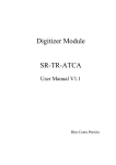
1
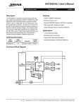
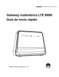
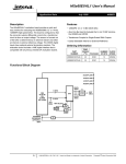
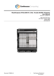
DS91D176
Multipoint-LVDS (M-LVDS) Transceiver
Evaluation Kit User Manual
April 2006
Rev 0.2
DS91D176 Evaluation Board User Manual
Overview
The purpose of this document is to familiarize you with the DS91D176 evaluation board, suggest the test setup
procedures and instrumentation, and to guide you through some typical measurements that will demonstrate the
performance of the device.
The primary function of the board is to assist a system designer in development and analysis of an M-LVDS
clock distribution network in an ATCA backplane. The board also enables the user to examine performance and
all functions of the DS91D176 as a standalone device. As a side feature, one can utilize the board to access
switch fabric interface of an ATCA backplane.
The DS91D176 is a high-speed M-LVDS differential transceiver designed for multipoint applications with
multiple drivers or receivers. The device conforms to TIA/EIA-899 standard. It utilizes M-LVDS technology for
low power, high-speed and superior noise immunity.
Description
Figure 1 below represents the top layer drawing of the board with the silkscreen annotations. It is a 6 x 4 inch
10 layer printed circuit board (PCB) that features seven DS91D176 (U1-U7) devices.
Figure 1: DS91D176 Evaluation Board - Top View
Devices U1 through U6 can serve as building blocks for M-LVDS clock distribution networks in ATCA
backplanes. Their M-LVDS I/O pins directly connect to the first two row pins of J4, which is an ADF (Advanced
Differential Fabric) connector. When J4 is inserted into any ATCA backplane slot (location J20/P20 for those of
you familiar with ATCA backplanes), the M-LVDS I/O pins of each device electrically connect to one of the clock
busses (there are six clock busses in an ATCA backplane – See Figure 3). The PCB traces that connect device
M-LVDS pins with the J4 connector pins have different characteristics for each device. These traces are also
2
DS91D176 Evaluation Board User Manual
called stubs. Table 1 provides characteristic of each stub, M-LVDS pins to J4 pin mapping and LVCMOS pins
to J2 pins mapping.
Device
U1
U2
U3
U4
U5
U6
M-LVDS Pins
A1
B1
A2
B2
A3
B3
A4
B4
A5
B5
A6
B6
J4 Pins
B1
A1
D1
C1
F1
E1
H1
G1
D2
C2
B2
A2
Stub Length
0.25”
ZSTUB
100 Ω
0.50”
100 Ω
1.00”
130 Ω
1.00”
100 Ω
1.00”
80 Ω
2.00”
100 Ω
LVCMOS Pins
R1
D1
R1
D1
R1
D1
R1
D1
R1
D1
R1
D1
J2 Pins
2
4
6
8
10
12
14
16
18
20
22
24
Table 1: U1-U6 Stub Characteristics and Pin Mapping
J1 configures U1 through U6 as either driver or receiver.
J7 and J8 are power and ground banana plug receptacles. J5 and J6 are redundant power and ground
connections.
U7 is for a standalone evaluation. Its I/O pins (both, M-LVDS and LVCMOS) connect to SMA connectors
(SMA5-SMA8) for easy interface with instrumentation. J3 configures U7 as either driver or receiver. There is a
provision to terminate M-LVDS inputs of the U7 with a SM0603 sized resistor.
Connectors, SMA1, SMA2, SMA3 and SMA4 connect to J4 pins H2, G2, F2 and E2 respectively. If the board is
plugged in an ATCA backplane, locations J21/P21, J22/P22, J23/P23 and J24/P24 in any slot, fabric interface is
accessed with these connectors.
Figure 2 provides a simplified block diagram view of the signal paths between the connecters and IC’s.
3
DS91D176 Evaluation Board User Manual
Figure 2. Simplified Signal Path Block Diagram
4
DS91D176 Evaluation Board User Manual
Building an Evaluation M-LVDS Clock Distribution Network in an
ATCA Backplane
The following is a recommended procedure for building an evaluation M-LVDS clock distribution network with
DS91D176 evaluation boards. The assumption is that the user already has an ATCA backplane. Figure 3
depicts configuration of a generic M-LVDS clock network in an ATCA backplane.
1. Use two or more DS91D176 evaluation boards and install them at backplane location J20/P20, in the
desired slots.
2. Apply the power to the boards (3.3 V typical) between J7 and J8 banana plug receptacles, observe the
value of ICC, and compare it with the expected value (refer to the datasheet) to ensure that the devices
are functional.
3. Select the board you want to configure as a clock driver/distributor. This is accomplished by setting DE
and RE* pins to VDD (J1). Connect a clock generator to one of the driver inputs (J2).
4. Configure the remaining boards as clock receivers. This is accomplished by setting DE and RE* pins to
GND (J1).
5. Observe clock waveforms by either connecting receiver LVCMOS output pins (J1) directly to an
oscilloscope or by probing receiver M-LVDS input pins with a differential probe.
Figure 3. M-LVDS Clock Distribution Network in an ATCA Backplane
The above block diagram details the clock channels. They are all 130-ohm differential and doubly terminated
with 80 ohms at either end of the backplane. The parallel combination of 80-ohm resistors means that the
MLVDS devices will be driving a 40-ohm load termination. The maximum stub length from the backplane is
defined in the ATCA standard as 1 inch or 2.5 cm.
5
DS91D176 Evaluation Board User Manual
Figure 4 shows a picture of a 14-slot ATCA backplane fully populated with DS91D176 evaluation boards.
Figure 4. DS91D176 Evaluation Boards in an ATCA Backplane
Figure 5 shows 19.44 MHz clock waveforms obtained with a differential probe, Tektronix P6330, on the M-LVDS
input pins of U1, U2, U4 and U6 devices of the receiver board in slot #8. The14-Slot backplane was fully
populated. The clock driver/distributor board was in slot #7.
Figure 5. 19.44 MHz Clock Waveforms Show Stub Length Effects on Signal Integrity
6
DS91D176 Evaluation Board User Manual
Building an Evaluation Point-Point Link with DS91D176
Evaluation Boards
The following is a recommended procedure for building an evaluation M-LVDS point-point network with
DS91D176 evaluation boards. Figure 6 depicts a typical setup and instrumentation used for evaluation of a
point-to-point link.
1. Use two DS91D176 evaluation boards
2. Apply the power to the boards (3.3 V typical) between J7 and J8 banana plug receptacles, observe the
value of ICC, and compare it with the expected value (refer to the datasheet) to ensure that the devices
are functional.
3. Configure U7 on one board as a driver. This is accomplished by setting DE and RE* pins to VDD (J3).
Connect a signal generator to the driver inputs (SMA6).
4. Configure U7 on the other board as a receiver. This is accomplished by setting DE and RE* pins to
GND (J3).
5. Select a differential interconnect with balanced 100-ohm differential impedance (i.e. UTP cable) and
connect the M-LVDS pins of both devices with it.
6. Terminate the interconnect with a matching resistor on the inputs of U7 on the receiver board (R1).
7. Observe waveforms by either connecting the receiver LVCMOS output pins (SMA5) directly to an
oscilloscope or by probing receiver M-LVDS input pins with a differential probe.
Figure 6. M-LVDS Point to Point Link with DS91D176 Boards and UTP Cable
7
DS91D176 Evaluation Board User Manual
Figure 7 shows eye diagrams acquired at the output of the DS91D176 driver loaded with a 100-ohm resistor and
after 50 m Cat5e cable terminated with a 100-ohm resistor. The generator connected to the driver input
simulated a 100 Mb/s PRBS-7 NRZ.
Figure 7: Eye Diagram Before and After 50 m of Cat5e
8
DS91D176 Evaluation Board User Manual
Microstrip and Stripline Geometries Used
Figures 8 to 12 show trace geometries used in the board design. Table 2 provides trace type to electrical
net cross-reference.
Trace Type / Figure
50-ohm Single-ended Microstrip / Figure 8
100-ohm Differential Microstrip / Figure 9
100-ohm Differential Stripline / Figure 10
130-ohm Differential Stripline / Figure 11
80-ohm Differential Stripline / Figure 12
DS91D176 Evaluation Board Nets
All LVCMOS nets
U7 M-LVDS nets, SMA1-SMA4 nets
U1, U2, U4, U6 M-LVDS nets
U3 M-LVDS nets
U5 M-LVDS nets
Table 2: Trace Type to Electrical Net Cross-reference.
Figure 8. 50-ohm Single-ended Microstrip
9
DS91D176 Evaluation Board User Manual
Figure 9. 100-ohm Differential Microstrip
Figure 10. 100-ohm Differential Stripline
10
DS91D176 Evaluation Board User Manual
Figure 11. 130-ohm Differential Stripline
Figure 12. 80-ohm Differential Stripline
11
DS91D176 Evaluation Board User Manual
Layer Stack Up:
1/2 oz. ------------------- SIG1
10 mills
1/2 oz. --------------------GND
15 mills
1/2 oz. ------------------- SIG2
15 mills
1/2 oz. --------------------GND
3 mills
1/2 oz. --------------------PWR
3 mills
1/2 oz. ------------------- PWR
3 mills
1/2 oz. --------------------GND
15 mills
1/2 oz. ------------------- SIG3
15 mills
1/2 oz. ------------------- GND
10 mills
1/2 oz. ------------------- SIG4
Bill Of Materials
Item
Quantity
Reference
Part
_____________________________________________________
1
2
2
9
3
9
4
5
6
7
8
9
10
11
11
12
2
1
1
2
1
1
4
4
7
1
C18, C1
C2, C4, C5, C6, C7, C8, C9, C10,
C19
C3, C11, C12, C13, C14, C15,
C16, C17, C20
J3, J1
J2
J4
J5, J6
J7
J8
SMA1, SMA2, SMA3, SMA4,
SMA5, SMA6, SMA7, SMA8
U1, U2, U3, U4, U5, U6, U7
R1
22u; SM7343; C1 Not Installed;
0.1u; SM0603; C2 Not Installed;
0.01u; SM0603; C3 Not Installed;
Molex 90131-0123
Molex 90130-3124
Tyco HM-ZD 1469001-1
Pomona 3267; Not Installed;
Johnson Components 108-0902-001
Johnson Components 108-0903-001
Not Installed;
Johnson Components 142-0701-231
DS91D176TMA
50; SM0603; Not Installed;
12
DS91D176 Evaluation Board User Manual
Schematic
J3
VCC_3V
DE1
GND
U2
R2
RE1*
DE1
D2
SMA1
4
5
GND
GND
SIG
1
TX+
GND
GND
SIG
1
TX-
GND
GND
SMA3
2
3
4
5
GND
GND
SIG
1
RX+
1
3
5
7
9
11
13
15
17
19
21
23
1
3
5
7
9
11
13
15
17
19
21
23
2
4
6
8
10
12
14
16
18
20
22
24
2
4
6
8
10
12
14
16
18
20
22
24
U3
R3
RE1*
DE1
D3
4
5
A1
B1
BG1
C1
D1
DG1
E1
F1
FG1
G1
H1
HG1
B2
A2
GND
1
2
3
4
R VCC
RE*
B
DE
A
D GND
VCC_3V
8
7
6
5
U4
R4
RE1*
DE1
D4
1
2
3
4
R5
RE1*
DE1
D5
1
2
3
4
Molex 90130-3124
R VCC
RE*
B
DE
A
D GND
8
7
6
5
U5
SIG
TX+
TXGND
RX+
RXGND
VCC_3V
B4
A4
GND
DS91D176TMA
GND
GND
GND
GND
B3
A3
GND
DS91D176TMA
SMA4
2
3
8
7
6
5
J2
GND
4
5
R VCC
RE*
B
DE
A
D GND
DS91D176TMA
GND
GND
SMA2
2
3
1
2
3
4
1
RX-
R VCC
RE*
B
DE
A
D GND
VCC_3V
8
7
6
5
A2
B2
BG2
C2
D2
DG2
E2
F2
FG2
G2
H2
HG2
B5
A5
GND
U6
GND
1
2
3
4
R VCC
RE*
B
DE
A
D GND
SIG
1
U7
R7
RE2*
DE2
D7
GND
GND
GND
SMA7
4
5
1
2
3
4
R VCC
RE*
B
DE
A
D GND
VCC_3V
8
7
6
5
1
B7
A7
GND
GND
SIG
GND
GND
R1
50
GND
GND
1
SIG
1
Not Installed
GND
GND
5
4
J5
3
2
1
1
VCC_3V
SMA8
DS91D176TMA
SMA6
2
3
A6
B6
BG6
C6
D6
DG6
E6
F6
FG6
G6
H6
HG6
B6
A6
GND
DS91D176TMA
4
5
A6
B6
GND
C6
D6
GND
E6
F6
GND
G6
H6
GND
A7
B7
BG7
C7
D7
DG7
E7
F7
FG7
G7
H7
HG7
VCC_3V
8
7
6
5
SMA5
GND
GND
Tyco HM-ZD 1469001-1
A2
B2
GND
C2
D2
GND
E2
F2
GND
G2
H2
GND
A7
B7
GND
C7
D7
GND
E7
F7
GND
G7
H7
GND
DS91D176TMA
GND
GND
R6
RE1*
DE1
D6
2
3
A1
B1
GND
C1
D1
GND
E1
F1
GND
G1
H1
GND
A3
B3
BG3
C3
D3
DG3
E3
F3
FG3
G3
H3
HG3
2
3
J4
VCC_3V
A5
B5
GND
C5
D5
GND
E5
F5
GND
G5
H5
GND
DS91D176TMA
A8
B8
GND
C8
D8
GND
E8
F8
GND
G8
H8
GND
B1
A1
GND
A8
B8
BG8
C8
D8
DG8
E8
F8
FG8
G8
H8
HG8
VCC_3V
8
7
6
5
A5
B5
BG5
C5
D5
DG5
E5
F5
FG5
G5
H5
HG5
R VCC
RE*
B
DE
A
D GND
A9
B9
BG9
C9
D9
DG9
E9
F9
FG9
G9
H9
HG9
1
2
3
4
A9
B9
GND
C9
D9
GND
E9
F9
GND
G9
H9
GND
U1
R1
RE1*
DE1
D1
Molex 90131-0123
A4
B4
GND
C4
D4
GND
E4
F4
GND
G4
H4
GND
2
4
6
A4
B4
BG4
C4
D4
DG4
E4
F4
FG4
G4
H4
HG4
2
4
6
A10
B10
BG10
C10
D10
DG10
E10
F10
FG10
G10
H10
HG10
1
3
5
A10
B10
GND
C10
D10
GND
E10
F10
GND
G10
H10
GND
1
3
5
A3
B3
GND
C3
D3
GND
E3
F3
GND
G3
H3
GND
VCC_3V
RE1*
GND
Pomona 3267
GND
GND
SIG
GND
GND
5
4
C3
0.01u
C2
0.1u
+
C1
22u
J6
GND
3
2
1
GND
1
Pomona 3267
J7
1
VCC_3V
1
VCC_3V
J1
VCC_3V
RE2*
GND
1
3
5
1
3
5
2
4
6
2
4
6
VCC_3V
DE2
GND
Molex 90131-0123
GND
C10
0.1u
C9
0.1u
C8
0.1u
C7
0.1u
C6
0.1u
C5
0.1u
C4
0.1u
Johnson Components 108-0902-001
C20
0.01u
C19
0.1u
+
C18
22u
J8
GND
Place one 0.1uF and one 0.01uF cap close to VDD pin of each DS91D176
1
1
VCC_3V
Johnson Components 108-0903-001
GND
C17
0.01u
C16
0.01u
C15
0.01u
C14
0.01u
C13
0.01u
C12
0.01u
C11
0.01u
Title
ATCA Line Card
Size
B
Date:
13
Document Number
M-LVDS
Wednesday, January 18, 2006
Rev
0.2
Sheet
1
of
1
DS91D176 Evaluation Board User Manual
Revision History
Revision 0.1: Initial draft – dglisic 12Apr2006
Revision 0.2: Minor edits, added simplified block diagram – bstearns 14 April2006
15