1
Chapter 7: Sending Messages From a PLC to ViewMarq
1
2
3
4
5
6
7
8
9
10
11
12
13
14
A
B
C
D
7–80
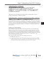
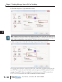
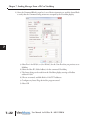
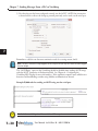
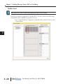
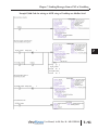
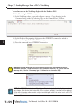
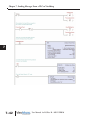
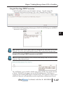
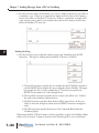
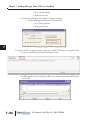
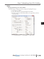
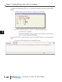
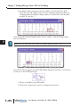
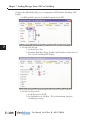
2) Now that we know where the remainder is, we can do a simple comparison to see if there is
a remainder or not. If there is no remainder we simply move the count to the V-memory
location that will be our Modbus TCP write size. If there is a remainder, we simply add 1
to the original count to make it even and place the result in the V-memory location that
will be our Modbus TCP write size.
Sending the String
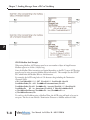
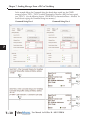
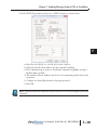
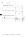
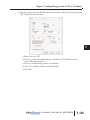
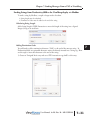
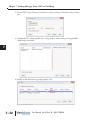
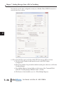
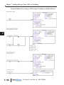
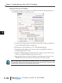
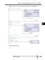
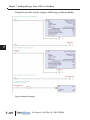
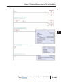
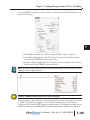
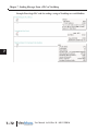
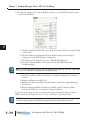
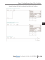
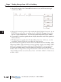
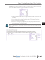
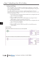
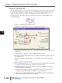
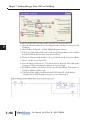
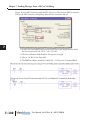
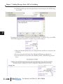
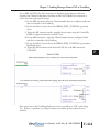
1) Now that the byte count is adjusted, send the string to the ViewMarq using the WX
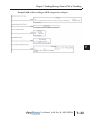
instruction. The logic for sending the first Modbus TCP write is as follows:
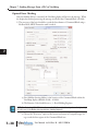
a) The first LD instruction specifies the slot number that the ECOM100 is located in
and the RX/WX Device number that was configured earlier in NetEdit. The upper
byte specifies the Slot (2 in the example above). The lower byte specifies the
RX/WX Device number (01 in the example above).
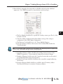
b) The second LD instruction specifies the size, in bytes, that will be sent. V3000 is
the result of the calculation explained above.
c) The LDA instruction specifies where the data will be written from. In this case,
V2001 is where the String data resides from the VPRINT instruction configured
earlier.
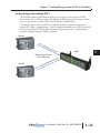
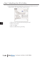
d) The WX instruction specifies the location of the Command Block within the
ViewMarq display.
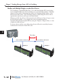
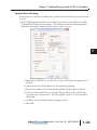
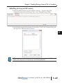
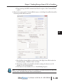
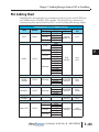
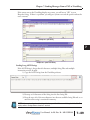
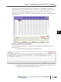
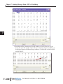
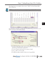
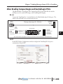
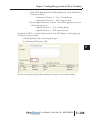
When doing Modbus TCP, the V-memory location specified is an alias of the Modbus address
and has to be converted. V-memory locations in the DirectLogic PLCs are in octal format.
User Manual, 1st Ed. Rev. B – MD-USER-M