1
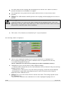
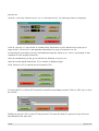
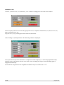
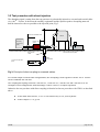
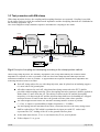
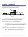
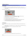
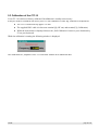
USER MANUAL
CIT-10
CIT-10/75
RF - GENERATOR / AMPLIFIER
HF-VOLTMETER
Available from Credence Technologies, Inc. Tel 831.459.7488, Fax 831.427.3513,http://www.credencetech.com
Software-Version 1.13
13.10.2000
Contents
1.0 Introduction................................................................................................................................3
Safety Summary................................................................................................................................3
Accessories supplied with CIT-10:....................................................................................................3
Introduction......................................................................................................................................4
2.0 Installation and Configuration.....................................................................................................5
Hardware- and Software Requirements and Installation....................................................................5
Installation of NI-DAQ driver software and DAQ hardware..............................................................5
Installation of CIT-10 application software.......................................................................................5
Front Panel Features.........................................................................................................................6
Rear Panel Features..........................................................................................................................7
Installation of CIT-10.......................................................................................................................8
Operation..........................................................................................................................................8
3.0 Making Tests..............................................................................................................................9
3.1 Test procedure with coupling/decoupling networks.....................................................................9
Complete Test................................................................................................................................11
Selective Test.................................................................................................................................13
3.2 Test procedure with direct injection..........................................................................................14
3.3 Test procedure with EM-clamp.................................................................................................15
4.0 Calibration of Coupling Devices................................................................................................16
5.0 Miscellaneous...........................................................................................................................18
5.1 Generator..................................................................................................................................18
5.2 Voltmeter..................................................................................................................................18
5.3 Calibration of the CIT-10..........................................................................................................19
5.4 Accessory.................................................................................................................................20
5.5 Specifications............................................................................................................................21
5.6 Factory Calibration of the CIT-10.............................................................................................22
CIT-10
page 2 of 22
1.0 Introduction
Safety Summary
The following general safety precautions must be observed during all phases of operation, service, and
repair of this instrument. Failure to comply with these precautions or with specific warnings elsewhere in
this manual violates safety standards of design, manufacture, and intended use of this instrument.
We assume no liability for the customer´s failure to comply with these requirements.
Before applying power:
Verify that the product is set to match the available line voltage and that the correct fuse is
installed.
Ground the instrument:
This product is a Safety Class 1 Product (provided with a protective earthing ground incorporated
in the power cord). The mains plug shall only be inserted in a socket outlet provided with a
protective earth contact. Any interruption of the protective conductor inside or outside of the
product is likely to make the product dangerous. Intentional interruption is prohibited.
Do not remove instrument covers:
Operating personnel must not remove instrument covers. There are no user serviceable parts
inside. Refer servicing to qualified personnel.
The CIT-10 shall only be operated by qualified personnel.
Extensive knowledge of the Basic Standard is mandatory.
The CIT-10 generates electromagnetic disturbances if operated as intended.
In case of doubt the test setup shall be in a shielded room.
Accessories supplied with CIT-10:
PCI-6503, I/O-Card (ISA-Card on request)
Power cord
BNC cable, 1,5m
Earth cable, 0,75m
Attennuator
Control cable, 3m; with PC-Interface
Software WIN95/98, WIN NT, WIN 2000
CIT-10
page 3 of 22
Introduction
Your CIT-10 is a fully automated system to perform immunity tests to conducted disturbances induced by
radio frequency fields according to EN 61000-4-6/IEC 1000-4-6.
The integrated broadband power amplifier (Class A) is capable of driving coupling/decoupling networks
(CDN) as well as the EM-Clamp up to the highest test levels (U0=10V, Level 3) with exellent signal
quality.
Network
Network
Internet
Intranet
Equipment
under Test
PC-based CIT-10
Data Akquisition Card
Fig.1: Principle of computer-based instrument
Your CIT-10 is a computer-based instrument. A computer-based system can perform the same tasks as
traditionel instruments with the added benefits of flexibility and efficiency.
Once the driver and application software are installed you immediately start testing. The results are
printed, saved or distributed over your companies intranet or the world wide web.
The calibration for all coupling/decoupling devices is performed automatically, with the software creating a
specific calibration file for any individual CDN or EM-clamp. No calibration at all is needed for our CDNs
or EM-clamp - they are delivered factory calibrated with a calibration file.
Our software is programmed in LabVIEW, the industry´s most popular instrumentation software. This
makes it easy to integrate our application software into measurement and automation systems.
Every analog or digital signal of the EUT may be monitored with a separate DAQ-card or with
ANA_1020, signal acquisition module (only analog signals). So it´s easy to display the EUT´s output
signal as a function of the disturbing frequency.
The CIT-10 is composed by three function blocks, which can all be driven separately: RF-generator, broad
band power amplifier and RF-voltmeter.
CIT-10
page 4 of 22
2.0 Installation and Configuration
Hardware- and Software Requirements and Installation
You should have the following hardware and software to work with your CIT-10:
PC with Windows 95/98 or Windows NT operating system, compatible mouse and VGA graphics
(min. 800 x 600 pts.).
Follow the next four steps:
Step 1 : Install your NI-DAQ driver software
Step 2 : Install your DAQ hardware device
Step 3 : Install your CIT-10 application software
Step 4 : Connect your CIT-10 and start operation
Installation of NI-DAQ driver software and DAQ hardware
All running applications on your PC must be closed.
Insert your NI-DAQ driver CD and click on setup.exe. Follow the installation wizard and
choose the default values at „Select components“.
After installing your driver software, you are ready to install the DAQ board into your
computer.
In all cases, install your NI-DAQ software prior to installing your DAQ hardware!
Reboot your computer.
Configure your device using the NI-DAQ Configuration Utility.
Enter „device number“ 2.
Installation of CIT-10 application software
Insert the application software CD and click on setup.exe
Follow the instructions on your screen.
The installer creates a directory named „CDG_E“, where you can doubleclick on
„61000-4-6.exe“ to start the application.
Copy the calibration files of your coupling/decoupling devices into the directory CDG_E/Data.
CIT-10
page 5 of 22
Front Panel Features
3
2
1
4
5
[1]: Earth Terminal
For connection of the supplied earth cable to the ground reference plane.
[2]: HF in
Input of the RF-Voltmeter
[3]: Thermal Protection
Indicates thermal overload of the power amplifier. Cooling down resets the amplifier
automatically.
[4]: HF out
Output of the broadband power amplifier
[5]: Power
Line switch turns the CIT-10 on and off
CIT-10
page 6 of 22
Rear Panel Features
14
Amplifier
in
Generator
out
6
7
8
Centronics-Buchse
EUT
fail
9
AM
extern
12
10
13
11
Artificial
Hand
[6]: Centronics-Connector, 36-pol
Connect to Centronics cable. Connect the PC-Interface between Centronics cable and your
computer´s DAQ card.
[7]: EUT fail
TTL/CMOS compatible input. Stops running application or sets a frequency mark.
[8]: Generator out
Drives the built in broadband power amplifier. Connected to [10] (default). May be split up for
use with external power amplifiers.
[9]: AM extern
Input for external modulation signal, for generation of non-standard amplitude modulated test
signals.
[10]: Amplifier in
Input of broadband power amplifier. Connected to [8] (default).
[11]: Artificial Hand
Input for artificial hand in accordance with IEC CISPR 16-1 (200pF and 500
series to ground).
connected in
[12]: Power input
Input for the line power source.
Line Fuse: Replace only with a fuse of the same rating. See the label on the rear panel.
[13]: Earth Terminal
Same as [1] on front panel.
[14]: Voltage selector - verify that the product is set to match the available line voltage
CIT-10
page 7 of 22
Installation of CIT-10
Connect the supplied power cable to terminal [12] on the back panel.
Connect the PC-Interface to the DAQ card in your computer.
Connect the Centronics cable between PC-Interface and your CIT-10.
The test set up for table-top and floor-standing equipment is according to chapter 7 of
EN 61000-4-6.
CIT-10: Connect the supplied BNC cable between amplifier out [4] and the supplied 6 dBattenuator. The 6 dB-attenuator should be placed to the coupling device as near as possible.
Operation
After installing the CIT-10 and arranging the test set up, you are ready to
Double-click on „61000-4-6.exe“ (Directory „CDG_E/61000-4-6.exe“).
The following window is displayed.
Press the „Generator“ button to operate the RF-Generator as a „stand alone“-device. For more
information see chapter 5.1.
Press the „RF-Voltmeter“ button to operate the RF-Voltmeter as a „stand alone“-device. For
more information see chapter 5.2.
Press the „Test“ button to perform immunity tests according to EN 61000-4-6. For more
information see chapter 3.
Press the „CDN-Calibration“ button to comfortably calibrate any coupling/decoupling device.
A calibration file is generated automatically. For more information see chapter 4.
Press the „Self-Calibration“ button, to generate a new CIT-10 calibration file. For more
information see chapter 5.3.
CIT-10
page 8 of 22
3.0 Making Tests
Tests with different injection methods are described in the following pages. If suitable CDNs are available
they shall be used. For coupling of supply lines CDNs are mandatory! For screened cables direct injection
shall be used. For multi-conductor cables and bundles of cables the EM-clamp shall be selected.
3.1 Test procedure with coupling/decoupling networks
The test set up for a single safety class 2 product is shown in Fig.2.
50
CDN-T2
0,5 m
To AE or
telecomm. lines
Balanced pair
50
Mains
CDN-M2
Mains
EUT
Unscreened
unbalanced
two-wire
CDN-AF2
Insulating support
h = 0,1 m
AE
6 dB
Attenuator
Reference ground plane
Conducted Disturbances
Test generator
Fig.2: Test setup for a single safety class 2 product
All instructions of the basic standard should be noticed.
The EUT shall be placed on an insulating support, 0,1 metre above the ground reference plane.
For table-top equipment, the ground reference plane may be placed on a table.
On all cables to be tested, coupling and decoupling devices shall be inserted.
The coupling and decoupling devices shall be placed on the ground reference plane, making
direct contact with it at about 0,1 - 0,3 metre from the EUT.
CIT-10
page 9 of 22
The cables between the coupling and decoupling devices and the EUT shall be as short as
possible and shall never be bundled or wrapped.
Their height above the ground reference plane shall be between 30 and 50 mm (where
possible).
CIT-10: The 6 dB attenuator shall be placed to the coupling and decoupling device as near as
possible.
Warning!
Capacitors bridge to live parts in the mains coupling and decoupling networks. Due to the
high leakage currents, mains CDNs shall have a earth terminal which shall remain connected to
the protective earth (PE) under all test conditions.
Click on the „Test“ button or use function key F1 on your keyboard.
The following window is displayed:
Choose your coupling/decoupling device from the selector box „Coupling device“.
Each coupling/decoupling device whose calibration files are copied into the directory
CIT10\Data is displayed in this box.
Choose calibration level and test level identical to achieve maximum accuracy!
„Standard test“ gives you the choice of three different settings:
- „Calibration fixed“ means that test level and calibration level are identical. Only start and stop
frequency may be varied.
- „Calibration free“ allows you to vary start and stop frequency, dwell time and modulation.
- „Extrapolation“ means that each parameter may be varied. Even the test level may be
different from the calibration level.
CIT-10
CIT-10: Enter your test level into the box with the same name. This setting depends on the
box „Standard test“:
- the test level is identical to the calibration level of the coupling/decoupling device if
page 10 of 22
FRANKONIA
EMV-Mess-Systeme GmbH
„Calibration fixed“ or „Calibration free“ is displayed in the box „Standard test“
- enter values between 1 V and 10 V if „Extrapolation“ is displayed. Enter values between
10 V and 15 V if the coupling/decoupling device was calibrated without the 6dB attenuator
(Precompliance)
CIT-10/75: Enter your test level into the box with the same name. This setting depends on the
box „Standard test“:
- the test level is identical to the calibration level of the coupling/decoupling device if
„Calibration fixed“ or „Calibration free“ is displayed in the box „Standard test“
- enter values between 1 V and 25 V if „Extrapolation“ is displayed.
Minimum value of start frequency is 0,15 MHz
Maximum value of stop frequency is 230 MHz
Frequency steps may vary between 0,1% and 100% (except standard levels)
Dwell time may vary between 0,2 s and 100 s (except standard levels)
The box „Modulation“ may be switched between internal and external modulation. If you need
non-standard test signals choose „external“. The external modulation signal shall be connected
to terminal [9] on the instruments back panel.
„EUT fail signal“ indicates how the programm shall react if a high level is connected to
terminal [7] on the instruments back panel.
„Test Stop“ means, the programm stops if a high-level is recognized
„No Test Stop“ sets a frequency mark which may be edited after test stop
The directory for the calibration files is displayed at the bottom of the window. It may be
altered on request. Each coupling/decoupling device whose calibration file is copied into this
directory is displayed in the box „Coupling device“.
Now you have to choose wether a complete test (sweep from start frequency to stop frequency) or a
selective test (choose a single frequency) is performed.
Complete Test
Click on „Complete Test“ or press function key F1.The following window is displayed:
Frequency and generator level are displayed while the test is running.
If the EUT shows any reaction to the injected disturbing frequencies, you may set a frequency mark by
pressing function key F10. After test stop you may edit this list of frequency marks, add comments, save or
CIT-10
page 11 of 22
print the list.
Click the „Test Stop“ button or press „esc“ to interrupt the test. The following window is displayed:
Click on „Step up“ or „Step down“ to examin nearby frequencies or press function keys (Page up) or
(Page down). Test level (F1) and amplitude modulation (F2) may be switched on or off.
Even during the interruption you may add additional frequency marks (F10). There is a possibility to add
comments to each frequency mark too.
After the examination you may go on with the test (Return) or stop it (esc).
After the test has finally finished the „Test“-window is displayed again.
Click „Protocol“ (F3) to edit the list of frequencies (F4).
You may add (F1) or delete (F2) frequencies and add corresponding remarks. Click on „OK“ (esc) to close
the window.
Finally you may save (F2) or print (F3) the protocol. You may also load (F1) protocols of previous test
and edit them in the same way.
CIT-10
page 12 of 22
Selective Test
Click on „Selective test“ (F2) while the „Test“-window is displayed to show the next window:
Enter frequency and test level into the appropriate boxes. Amplitude modulation (F2) and test level (F1)
may be switched on or off.
Stop the test (esc) by clicking the button with the same name.
After clicking on „Ramp function“ the following window is displayed:
Now you can sweep from a startlevel to a stoplevel at fixed frequency. To start the programmed ramp
function click on the button with the same name. After reaching the stoplevel the disturbing signal is
stopped automatically.
Even with the ramp function the amplitude modulation may be switched on or off.
CIT-10
page 13 of 22
3.2 Test procedure with direct injection
The disturbing signal, coming from the test generator is galvanically injected to screened and coaxial cables
via a 100
resistor. In between the auxiliary equipment and the injection point a decoupling network
shall be inserted as close as possible to the injection point, Fig.3.
0,1 m < L < 0,3 m
W all of shielded room
EUT
*)
Auxiliary
equipm ent
(AE)
Ferrite ring
cores
50
CDN-M3
30m m
100
Short earth
cable
0,1 m
Ground reference plane
6dB
Attenuator
*) Close to injection
point
50
Test generator
Fig.3: Principle of direct coupling to screened cables.
For certain simple screened cable configurations, the decoupling circuit together with the 100
can be combined into one box.
resistor
The coupling/decoupling networks CDN 801-S1, CDN 801-S2, CDN 801-S9 and CDN 801-S25 are
examples of this configuration. Main advantage of these CDN´s is a simpler operation.
Otherwise the test pocedure with direct coupling is identical to the test procedure with CDN´s as described
above.
At the main menu choose „Test“ or use function key F1 on your keyboard.
CIT-10
Follow chapter 3.1 to go on.
page 14 of 22
3.3 Test procedure with EM-clamp
With clamp injection devices, the coupling and decoupling functions are separated. Coupling is provided
by the clamp-on device while the common-mode impedance and the decoupling functions are established at
the auxiliary equipment, Fig.4.
The electromagnetic clamp combines capacitive and inductive coupling to the cables.
L < 0,3 m where possible
0,1 m < L < 0,3 m
Ferrite
Auxiliary
equipm ent
(AE)
50
EUT
Clam p
injection
device
50
Z ce
CDN-M 3
CDN-M 3
30m m
Short connection
to earth
50
6dB
Attenuator
0,1 m
Ground reference plane
Test generator
Fig.4: Principle of coupling and decoupling according to the clamp injection method
When using clamp injection, the Auxiliary Equipment (AE) setup shall embody the common-mode
impedance as required as close as possible. Each AE used with clamp injection shall represent the
functional conditions as close as possible. To approximate the required common-mode impedance the
following measures need to be taken:
Each AE, being subject for use with clamp injection, must be placed on an insulating support
0,1 metre above the ground plane.
All cables connected to each AE, other than those being connected to the EUT, shall be
provided with decoupling networks. These decoupling networks (measures) shall be applied no
further than 0,3 metre from the AE. The cable(s) in between the AE and the decoupling
network(s) or in between the AE and the injection clamp shall never be bundled nor wrapped
and kept between 30 and 50 mm above the ground reference plane where possible.
The cable length in between the AE and the EM clamp shall be as short as possible
(≤ 0,3m), to improve reproducibility at higher frequencies (> 30 MHz).
The decoupling network installed on the cable, electrically closest to the one(s) being tested
shall be replaced by a CDN which is terminated at its input port with 50Ω and as such
represents the 150Ω loading of the AE to the ground reference plane.
At the main menu choose „Test“ or use function key F1 on your keyboard.
CIT-10
Follow chapter 3.1 to go on.
page 15 of 22
4.0 Calibration of Coupling Devices
Coupling devices shall be calibrated before first use (except CDN´s from our company because these are
supplied with corresponding calibration files). (Re-) calibration is recommended if the test setup is different
from the calibration setup (e.g. different cables, different cable lengths etc.).
6 dB
Attenuator
30mm
150
Test generator
IN
*)
150
50
AE
EUT
to 50
adaptor
100
HF-Voltmeter
Coupling/decoupling
device
Ground reference plane
Common-mode
points
*) The 150 loading (e.g. a 150 to 50
adaptor terminated with a 50 load) at the AE-port shall
only be applied to unscreened cables (screened cables will have their screen connected to the ground
reference plane at the AE-side).
Fig.5: Setup for level setting at the EUT-port of coupling and decoupling devices
The setup for level setting is given in Fig.5 for all coupling and decoupling devices.
CIT-10: The test generator (HF-out) shall be connected to the RF-input port of the coupling
device via the 6dB-attenuator.
The EUT port of the coupling device shall be connected in common-mode through the 150
to 50 adaptor to the HF-Voltmeters (Calibration).
The AE-port shall be loaded in common-mode with a 150
50
to 50
adaptor, terminated with
Suitable calibration adaptors are available from our company for all coupling and decoupling devices.
CIT-10
Choose the „CDN-Calibration“ button or press function key F2 on your keyboard. The
following window is displayed:
page 16 of 22
Click on „Calibration Start“ Button (F1) to start the calibration.
You can choose the frequency range of calibration between 0.15 MHz to 80 MHz or
0.15 MHz to 230 MHz.
CIT-10: Enter test levels (calibration level) between 1V and 15V.
Maximum accuracy is achieved if test level and calibration level are identical.
CIT-10: For precompliance tests levels between 10V and 15V may be generated. Remove the
6dB attenuator at calibration levels above 10V.
CIT-10/75: Enter test levels (calibration level) between 1V and 25V.
Maximum accuracy is achieved if test level and calibration level are identical.
CIT-10/75: Connect attenuator (20 dB / 0,5 W) in between „Generator out“ [8] and
„ Amplifier in“ [10] on the back panel for small calibration levels (approx. < 2V).
Attention: Test setup and calibration setup must be identical – don´t forget the attenuator!
Frequency steps may vary between 0,1% and 100%.
Return to the main menue by clicking the button of the same name (esc).
CIT-10
page 17 of 22
5.0 Miscellaneous
5.1 Generator
The output signal of the RF generator is provided at terminal [8] on the rear panel of your CIT-10.
While the main menue is displayed choose the „Generator“ button or press function key F4 on
your keyboard.
The following window is displayed:
Type frequency and level in to the corresponding boxes. Displayed is always the nonmodulated signal level. Choose level units dBm, dB V or dBmV.
The signal level may be switched off or on.
The amplitude modulation (AM) may be switched off or on.
The amplitude modulation may be switched from internal to external. The input for the
external modulation signal is terminal [9] on the rear panel of your CIT-10.
Return to the main menue by clicking the button of the same name (esc).
5.2 Voltmeter
The signal input for the RF voltmeter is provided at terminal [2] (Calibration) on the front panel of your
CIT-10.
While the main menue is displayed choose the „Voltmeter“ button or press function key F5 on
your keyboard.
The following window is displayed. The value is displayed in dBm, dB V or dBmV.
Refresh time is 0.5 sec.
Return to the main menue by clicking the button of the same name (esc).
CIT-10
page 18 of 22
5.3 Calibration of the CIT-10
Your CIT-10 is delivered factory calibrated. Recalibration is usually not necessary.
It may be useful to recalibrate the device prior to CDN calibration or after big variations of temperature.
The CIT-10 shall warm up approx. 30 min.
The supplied BNC cable is in between terminal [4] (HF out) and terminal [2] (Calibration).
While the main menue is displayed choose the „Self-Calibration“ button or press function key
F3 on your keyboard.
While the calibration is running the following window is displayed.
The calibration file „Amplifier.CDG“ is overwritten with the new calibration data.
CIT-10
page 19 of 22
5.4 Accessory
The accessory listed below may be ordered by our company either with the CIT-10 or separately.
Coupling/decoupling networks
Typ
Application
AEConnector
EUTConnector
CDN 801-M1
unscreened supply (mains) lines
4mm MC-Sockets
4mm MC-Sockets
CDN 801-M2
unscreened supply (mains) lines
4mm MC-Sockets
4mm MC-Sockets
CDN 801-M3
unscreened supply (mains) lines
4mm MC-Sockets
4mm MC-Sockets
CDN 801-M5
unscreened supply (mains) lines
4mm MC-Sockets
4mm MC-Sockets
CDN 801-M2+M3
unscreened supply (mains) lines
4mm MC-Sockets
4mm MC-Sockets
CDN 801-S1
screened cables
BNC
BNC
CDN 801-S2
screened cables
XLR/Female
XLR/Male
CDN 801-S9
screened cables
SubD 9pin female
SubD 9pin male
CDN 801-S25
screened cables
SubD 25pin female
SubD 25pin male
CDN 801-AF2
unscreened nonbalanced lines
Terminal block
Terminal block
CDN 801-AF4
unscreened nonbalanced lines
Terminal block
Terminal block
CDN 801-AF6
unscreened nonbalanced lines
Terminal block
Terminal block
CDN 801-AF8
unscreened nonbalanced lines
Terminal block
Terminal block
CDN 801-T2
unscreened balanced pairs
Terminal block
Terminal block
CDN 801-T4
unscreened balanced pairs
Terminal block
Terminal block
CDN 801-T8
unscreened balanced pairs
Terminal block
Terminal block
CDN 801-RJ11
unscreened data lines
RJ11 Socket
RJ11 Socket
CDN 801-RJ45
screened data lines
RJ45 Socket
RJ45 Socket
CDN 801-USB-C
USB devices
USB-A
USB-B
CDN 801-USB-P
USB devices
USB-B
USB-A
Calibration adaptors for all coupling devices
ANA_1020, signal acquisition module for analog signals
EMC-testtable with ground plane (stainless steel); metalfree construction
Other accessories are available on request.
CIT-10
page 20 of 22
5.5 Specifications
RF Voltmeter
Frequency range
100 kHz to 266 MHz
Measuring range
+37 dBm to – 40 dBm
Accuracy
0,5 dB (+30 dBm to – 30 dBm)
1,0 dB (+37 dBm to – 40 dBm)
Resolution
0,1 dB
VSWR
< 1,1 : 1
Generator
Frequency range
100 kHz to 266 MHz
Resolution 1 Hz
Accuracy (frequency)
10 ppm
20 ppm
35 ppm
55 ppm
< 40 MHz
< 80 MHz
< 160 MHz
> 160 MHz
Output level
-40 dBm to 0 dBm
Resolution 0,1 dB
Linearity 0,5 dB ( 1 dB max)
Distortions
Harmonics < 30 dBc
Non-harmonics < 35 dBc
Amplitude modulation
1 kHz 3%, 80% 5% (internal)
10 Hz to 100 kHz, 0 to 90% (external)
Input impedance > 100 k
VSWR
< 1,3 : 1
Power amplifier
CIT-10
CIT-10/75
Frequency range
100 kHz to 266 MHz
100 kHz to 230 MHz
Gain
41 dBm
51 dBm
Output power
> 13 W
75 W
Distortion
< 20 dBc at nominal power
< 25 dBc at 40 W
< 2,0 : 1
< 1,2 : 1 (with 6 dB-attenuator)
< 1,5 : 1
VSWR
EUT-fail input
Input
Output
1,5 dB
1,0 dB
TTL/CMOS compatible
General data
Temperature range
0 to 40 ° C
Warm-up time
15 min
Housing
19“ Subrack or desktop case
Width / height / depth
84 TE / 3 HE / 365mm
Volume of delivery
CIT-10 (basic equipment), PCI digital I/O-Card, cabling,
attenuator, system software
CIT-10
page 21 of 22
5.6 Factory Calibration of the CIT-10
To ensure accuracy the CIT-10 shall be factory calibrated every year.
Available from Credence Technologies, Inc. Tel 831.459.7488, Fax 831.427.3513,http://www.credencetech.com
CIT-10
page 22 of 22