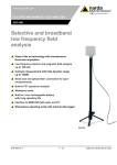
1
NARDA Safety Test Solutions S.r.l. Socio Unico Sales & Support: Via Leonardo da Vinci, 21/23 20090 Segrate (MI) - ITALY Tel.: +39 02 2699871 Fax: +39 02 26998700 Manufacturing Plant: Via Benessea, 29/B 17035 Cisano sul Neva (SV) Tel.: +39 0182 58641 Fax: +39 0182 586400 http://www.narda-sts.it User’s Manual PMM RA01 PMM RA01-HV ROD ANTENNA SYSTEM SERIAL NUMBER OF THE INSTRUMENT You can find the Serial Number in a side of the box. Serial Number is in the form : 0000X00000. The first four digits and the letter are the Serial Number prefix, the last five digits are the Serial Number suffix. The prefix is the same for identical instruments, it changes only when a configuration change is made to the instrument. The suffix is different for each instrument. Document RA01EN-01109 – Copyright © NARDA 2007 NOTE: ® Names and Logo are registered trademarks of Narda Safety Test Solutions GmbH and L3 Communications Holdings, Inc. – Trade names are trademarks of the owners. If the instrument is used in any other way than as described in this Users Manual, it may become unsafe Before using this product, the related documentation must be read with great care and fully understood to familiarize with all the safety prescriptions. To ensure the correct use and the maximum safety level, the User shall know all the instructions and recommendations contained in this document. This product is a Safety Class III instrument according to IEC classification and has been designed to meet the requirements of EN61010-1 (Safety Requirements for Electrical Equipment for Measurement, Control and Laboratory Use). In accordance with the IEC classification, the battery charger of this product meets requirements Safety Class II and Installation Category II (having double insulation and able to carry out mono-phase power supply operations). This product has a Pollution Degree II normally only non-conductive pollution occurs. Occasionally, however, a temporary conductivity caused by condensation must be expected. The information contained in this document is subject to change without notice. KEY TO THE ELECTRIC AND SAFETY SYMBOLS: You now own a high-quality instrument that will give you many years of reliable service. Nevertheless, even this product will eventually become obsolete. When that time comes, please remember that electronic equipment must be disposed of in accordance with local regulations. This product conforms to the WEEE Directive of the European Union (2002/96/EC) and belongs to Category 9 (Monitoring and Control Instruments). You can return the instrument to us free of charge for proper environment friendly disposal. You can obtain further information from your local NARDA Sales Partner or by visiting our website at www.narda-sts.it . Warning, danger of electric shock Earth Read carefully the Operating Manual and its instructions, pay attention to the safety symbols. Unit Earth Connection Earth Protection Equipotential KEY TO THE SYMBOLS USED IN THIS DOCUMENT: The DANGER sign draws attention to a potential risk to a person’s DANGER safety. All the precautions must be fully understood and applied before proceeding. WARNING The WARNING sign draws attention to a potential risk of damage to the apparatus or loss of data. All the precautions must be fully understood and applied before proceeding. CAUTION The CAUTION sign draws attention against unsafe practices for the apparatus functionality. NOTE: II The NOTE draw attention to important information. Note and symbols Contents Safety recommendations and instructions.………...... EC Conformity Certificate……....................................... Page V VI 1 General Information 1.1 Introduction…......................................................…... 1.2 Documentation…….…………………………………… 1.3 Introduction to PMM RA01……………………........... 1.4 Calibration of PMM RA01................................……... 1.5 The Antenna System..................................…............ 1.6 PMM RA01 Components.........................…...…........ Page 1-1 1-1 1-1 1-1 1-1 1-3 2 Mounting Instructions 2.1 Introduction………………………………………………. 2.2 Initial inspection…………………………………………. 2.3 Environment……………………………………………… 2.4 Return for service……………………………………….. 2.5 Equipment cleaning…………………………………….. 2.6 PMM RA01 mounting instructions…………………….. Page 2-1 2-1 2-1 2-1 2-1 2-2 3 Using PMM RA01 3.1 How it works……………………………………………… 3.2 Power Switch……………………………………………. 3.3 Battery Charging………………………………………… 3.4 ESD Risks………………………………………………... 3.5 Principles of operation………………………………….. 3.6 Antenna Factor………………………………………….. 3.7 Procedure of calibration………………………………… 3.8 Optional Accessories……………………………………. Page 3-1 3-1 3-1 3-1 3-1 3-2 3-2 3-2 Contents III Figures Figure 1-1 1-2 1-3 1-4 2-1 3-1 3-2 Page PMM RA01 Antenna System.…….……………………. Box Pre-Amplifier (part 1).…….……………………….. Monopole antenna (part 3 and part 4)……...…………. Antenna base (part 2)……….................…………....... Shot of montage of the PMM RA01 Antenna System.. PMM TR01 Wooden Tripod......................................... Mounting head with center column…………………….. 1-1 1-3 1-3 1-3 2-2 3-1 3-1 Tables Table Page Technical Specification………………….……………… Main features…………………………………………..… PMM TR01 Wooden Tripod…………………………..... 1-1 1-2 3-1 IV Contents 1-2 1-2 3-3 SAFETY RECOMMENDATIONS AND INSTRUCTIONS This product has been designed, produced and tested in Italy, and it left the factory in conditions fully complying with the current safety standards. To maintain it in safe conditions and ensure correct use, these general instructions must be fully understood and applied before the product is used. • When the device must be connected permanently, first provide effective grounding; • If the device must be connected to other equipment or accessories, make sure they are all safely grounded; • In case of devices permanently connected to the power supply, and lacking any fuses or other devices of mains protection, the power line must be equipped with adequate protection commensurate to the consumption of all the devices connected to it; • In case of connection of the device to the power mains, make sure before connection that the voltage selected on the voltage switch and the fuses are adequate for the voltage of the actual mains; • Devices in Safety Class I, equipped with connection to the power mains by means of cord and plug, can only be plugged into a socket equipped with a ground wire; • Any interruption or loosening of the ground wire or of a connecting power cable, inside or outside the device, will cause a potential risk for the safety of the personnel; • Ground connections must not be interrupted intentionally; • To prevent the possible danger of electrocution, do not remove any covers, panels or guards installed on the device, and refer only to NARDA Service Centers if maintenance should be necessary; • To maintain adequate protection from fire hazards, replace fuses only with others of the same type and rating; • Follow the safety regulations and any additional instructions in this manual to prevent accidents and damages. Safety consideration V EC Conformity Certificate (in accordance with the directives: EMC 89/336/EEC and low voltage 73/23/EEC) This is to certify that the product: PMM RA01 Antenna System Produced by: NARDA S.r.l. Safety Test Solution Via Benessea 29/B 17035 Cisano sul Neva (SV) - ITALY complies with the following European Standards Safety: EN 61010-1:1993 + A2:1995: EMC: EN 55011 - EN 50082-1; IEC: EN 1000-3-3 Standard This product complies with the requirements of the Low Voltage Directive 73/23/EEC, amended by 93/68/EEC, and the EMC Directive 89/336/EEC amended by 92/31/EEC, 93/68/EEC, 93/97/EEC. NARDA S.r.l. VI EC Conformity 1 – General Information 1.1 Introduction This manual is a guide to the installation and use of the PMM RA01 Antenna System. Main information about the radiated emission and immunity testing are also explained. 1.2 Documentation Enclosed with this manual are: • a service questionnaire to send back to NARDA if equipment service is required. • an accessories check list to verify all accessories enclosed in the packaging. 1.3 Introduction to the PMM RA01 Antenna System The PMM RA01 is designed to provide a good solution to measure low level fields from 9 kHz to 30 MHz (RA-01) and 150kHz to 30MHz (RA-01HV It is a good companion of all receivers or spectrum analyzers to cover lower bandwidth application. 1.4 Calibration of the PMM RA01 Antenna System Each antenna is individually calibrated. By knowing the actual antenna factors and performance characteristics of an antenna instead of typical data, you can more accurately calculate the field strength in your tests. Annual recalibration is recommended for rod antennas. 1.5 The Antenna System The Antenna System includes the following: • PMM RA-01 Box or RA-01-HV Box • PMM RA-01 monopole • Antenna Base plate • Battery Charger • Intern. AC plug adapter (Australia, UK,USA) • Italian AC Plug adapter • Carrying Case • Antenna certificate • Operating manual • Return for Repair Form Fig. 1-1 PMM RA01 Antenna System Document RA01EN-01109 - © NARDA 2007 General Information 1-1 TABLE 1-1 Technical specification Frequency range 9 kHz – 30 MHz (RA-01) 150kHz – 30 MHz (RA-01-HV) Impedance 50Ω Connector BNC female Battery 7.2V Operating time > 24 hours Recharging time < 6 hours Box size 150x135x120 (it can be mounted on the PMM TR-01 tripod via ¼ inch x 20 threads) Antenna size 1m (diam. 16mm) Weight 1.5 Kg 720mA TABLE 1-2 Main features • Low cost • Good flatness • Tripod mounting • Individual calibration • Easy to operate 1-2 General Information 1.6 PMM RA01 Components Legend: A= ON/OFF Switch B= Power LED C= Battery Charger cable D= BNC female connector Fig. 1-2 Box Pre-Amplifier and Adapting Impedance (part 1) Fig. 1-3 Monopole antenna part 3 and part 4 Fig. 1-4 Antenna base (part 2) General Information 1-3 This page has been intentionally left blank 1-4 General Information 2 – Mounting Instructions 2.1 Introduction This section provides the information needed to install and use your PMM RA01 Antenna System. Included are information pertinent to initial inspection, interconnection, environment, mechanical mounting, cleaning, storage and shipment. 2.2 Initial inspection Inspect the shipping container for damage. If the shipping container or cushion material is damaged, it should be kept until the contents of the shipment have been checked for completeness and the antennas have been checked mechanically and electrically. Verify the accessories availability in the shipping referring to the accessories check list enclosed. Notify any damage to the carrier personnel as well as the NARDA Representative. 2.3 Environment The PMM RA01 Antennas are constructed of lightweight corrosionresistant aluminum providing years of indoor and outdoor service. 2.4 Return for service If the Antenna System should be returned to NARDA for service, please complete the service questionnaire enclosed with the Users Manual and attach it to the instrument. To minimize the repair time, be as specific as possible when describing the failure. If possible, reuse of the original packaging to ship the equipment is preferable. In case other package should be used, ensure to wrap the instrument in heavy paper or plastic. Use a strong shipping container and use enough shock absorbing material around all sides of the equipment to provide a firm cushion and prevent movement in the container. Seal the shipping container securely. Mark the shipping container FRAGILE to encourage careful handling. 2.5 Equipment cleaning Use a clean, dry, non abrasive cloth for equipment cleaning. To clean the wooden tripod do not use any solvent, thinner, turpentine, acid, acetone or similar matter to avoid damage to it. Document RA01EN-01109 - © NARDA 2007 Mounting Instructions 2-1 2.6 PMM RA01 Mounting Instructions Before to start the installation, remove two screws from the box. Install the Antenna base (2) fixing it to the preamplifier box (1) with the two screws removed. Screw the monopole part (3) onto the monopole part (4) of the PMM RA01 and then screw the antenna to the preamplifier box. Fig. 2-1 Shots of montage of the PMM RA01 Antenna System 2-2 Mounting Instructions 3 – Using PMM RA01 3.1 How it works PMM RA01 is an active, high sensitivity Electric field receiving antenna. It has a built in preamplifier. It works as a short monopole over a ground plane. Its intrinsically high impedance within the covered frequency band is transformed and normalized by the internal preamplifier. 3.2 Power switch To turn the unit on and off push the black switch located on the side panel of the box. 3.3 Battery charging When the unit is on, the light from the green led placed inside the power switch indicates the remaining charge of the internal battery. So the light becomes weak when the battery voltage goes down. In this case the battery needs to be recharged. To charge the internal battery: switch the unit off, then plug the supplied AC battery charger in the supply mains and connect the apposite connector to the ROD box. A WARNING In order to safeguard the features of the batteries, it is recommended to fully recharge it before using the antenna. Do not charger for more than 6 hours. It is warmly suggested to recharge the batteries at least every 4 months even though the device has not been used. 3.4 ESD risks A WARNING 3.5 Principles of operation Since the monopole terminal is directly connected to the high sensitive preamplifier, built using a delicate Field Effect Transistor, it is important not to touch it before proper grounding and being sure to avoid ESD effects. The static charge carried by test personnel can damage the FET. The most important assumption to be done concerns the length of the monopole. If it is short enough, and it means less then 1/8 wavelength at the higher frequency of the covered band, the current distribution over the antenna can be approximated to be linear. The 1m length makes easy to calculate the field strength that is usually measured as Volts per meter. It is only necessary to take in count of the effective length of the antenna that is a half of its physical length. This means that a +6dB must be added to antenna factor when electric field strength is measured. In the meantime this length corresponds to a 1/8 wavelength at the frequency of about 37MHz, so it is possible to use it up to more then 30MHz. The ideal situation to use a rod antenna is when it operates in reference to an infinite ground plane. The small box containing the preamplifier should be connected to the real ground. If the case is not well grounded important reading differences can appear. The RA-01-HV model is protected from low-frequency disturbance signals by internal 150 kHz High Pass Filter (for example: Main Power 50/60 Hz) A WARNING A WARNING If radiated by electromagnetic fields higher than 5kV/m 50/60 Hz, the antenna can be damaged Please do not touch the Display of 9010 while using RA-01, in order to prevent measured E-field from being affected by wrong contribution through human body radiation 1 Document RA01EN-01109 - © NARDA 2007 Using PMM RA01 3-1 3.6 Antenna factor PMM RA01 is furnished together with its individual antenna factor calibration data. The antenna factor is the ratio of the field strength in which the antenna is immersed to the voltage coming out of the unit. A typical value for Rod antenna factor is about +10dB. If, for example, the output of the antenna is +44dBµV, and the antenna factor is +10dB at the radiated frequency, the electric field magnitude is: +44 +10 = +54 dBµV/m corresponding to 0.0005 V/m. 3.7 Procedure of Calibration PMM RA01 is calibrated in accordance with the equivalent capacitive substitution method, using equipment which certifications traceability to national and international standards are reported on the antenna certificate itself. 3.8 Optional accessories The possible options are: • • • • • • • • • • 3-2 Using PMM RA01 AS-03 : Antenna set (BC-01 Biconical Antenna, LP-02 Log-Periodic, LP-03 Log-Periodic, TR-01 Tripod, 5 m. cable, CC-01 Soft Carrying Case and CC-03 Soft Carrying Case) AS-02 : Antenna set (BC-01 Biconical Antenna, LP-02 Log-Periodic, TR-01 Tripod, 5 m. cable, CC-01 Soft Carrying Case) CTK-01 : Set of active Near Probes Credence Tecn. GTEM Cells RF-300 : Van Veen Loop TRF-1 : Balanced to unbalanced transformer 7000 Emission precompliance system 150kHz-1000MHz 9010/9030 EMI Receivers 10Hz-3GHz 8053 System for the measurement of electromagnetic fields TR01 Wooden tripod. TABLE 1-3 PMM TR01 Wooden tripod with extension and adjustable joint Specifications • legs 3 legs x 3 sections extensible • transportation width 76 x 12 x 12 cm • minimum height 60 cm • maximum height 180 cm • weight 2,8 kg • load capacity 10 kg Fig. 3-1 PMM TR01 Wooden Tripod It is possible to adjust legs spread at tree different angles, the adjustment is made rotating the knurled locking adjuster by selecting the corresponding marker on the knurled locking adjuster: • 20° spread : knurled locking adjuster white mark; • 45° spread : knurled locking adjuster red mark; • variable spread : knurled locking adjuster unmarked. Fig. 3-2 Mounting head with center column The central mast can be adjusted and fixed with the clamping lever. • Height: 7 cm • Weight: 180 g • Load capacity: 10 kg Using PMM RA01 3-3 This page has been intentionally left blank 3-4 Using PMM RA01 NARDA Safety Test Solutions S.r.l. Socio Unico Sales & Support: Via Leonardo da Vinci, 21/23 20090 Segrate (MI) - ITALY Tel.: +39 02 2699871 Fax: +39 02 26998700 Manufacturing Plant: Via Benessea, 29/B 17035 Cisano sul Neva (SV) Tel.: +39 0182 58641 Fax: +39 0182 586400 http://www.narda-sts.it Mod. 18-1 Caro cliente grazie per aver acquistato un prodotto NARDA! Sei in possesso di uno strumento che per molti anni ti garantirà un’alta qualità di servizio. NARDA riconosce l'importanza del Cliente come ragione di esistenza; ciascun commento e suggerimento, sottoposto all'attenzione della nostra organizzazione, è tenuto in grande considerazione. La nostra qualità è alla ricerca del miglioramento continuo. Se uno dei Suoi strumenti NARDA necessita di riparazione o calibrazione, può aiutarci a servirla più efficacemente compilando questa scheda e accludendola all’apparecchio. Tuttavia, anche questo prodotto diventerà obsoleto. In questo caso, ti ricordiamo che lo smaltimento dell'apparecchiatura deve essere fatto in conformità con i regolamenti locali. Questo prodotto è conforme alle direttive WEEE dell’Unione Europea (2002/96/EC) ed appartiene alla categoria 9 (strumenti di controllo). Lo smaltimento, in un ambiente adeguato, può avvenire anche attraverso la restituzione del prodotto alla NARDA senza sostenere alcuna spesa. Può ottenere ulteriori informazioni contattando i venditori NARDA o visitando il nostro sito Web www.narda-sts.it. Dear Customer thank you for purchasing a NARDA product! You now own a high-quality instrument that will give you many years of reliable service. NARDA recognizes the importance of the Customer as reason of existence; in this view, any comment and suggestion you would like to submit to the attention of our service organization is kept in great consideration. Moreover, we are continuously improving our quality, but we know this is a never ending process. We would be glad if our present efforts are pleasing you. Should one of your pieces of NARDA equipment need servicing you can help us serve you more effectively filling out this card and enclosing it with the product. Nevertheless, even this product will eventually become obsolete. When that time comes, please remember that electronic equipment must be disposed of in accordance with local regulations. This product conforms to the WEEE Directive of the European Union (2002/96/EC) and belongs to Category 9 (Monitoring and Control Instruments). You can return the instrument to us free of charge for proper environment friendly disposal. You can obtain further information from your local NARDA Sales Partner or by visiting our website at www.narda-sts.it. 5 Servizio richiesto: 5 Service needed: Solo taratura Calibration only Riparazione Repair Riparazione & Taratura Repair & Calibration Taratura SIT Certified Calibration Altro: Other: Ditta: Company: Indirizzo: Address: Persona da contattare: Technical contact person: Telefono: Phone n. Modello: Equipment model: Numero di serie: Serial n. 5 Accessori ritornati con l’apparecchiatura: Nessuno Cavo(i) Cavo di alimentazione 5 Accessories returned with unit: None Cable(s) Power cable Altro: Other: 5 Sintomi o problemi osservati: 5 Observed symptoms / problems: 5 Guasto: Fisso Intermittente 5 Failure: Continuous Intermittent Sensibile a : Freddo Sensitive to: Cold Caldo Heat Descrizione del guasto/condizioni di funzionamento: Failure symptoms/special control settings description: Se l’unità è parte di un sistema descriverne la configurazione: If unit is part of system please list other interconnected equipment and system set up: Vibrazioni Altro Vibration Other Suggerimenti / Commenti / Note: Suggestions / Comments / Note: