1
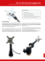
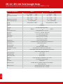
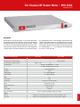
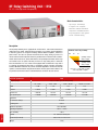
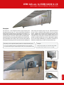
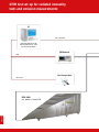
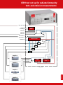
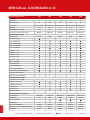
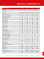
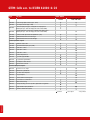
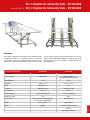
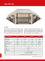
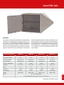
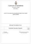
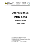
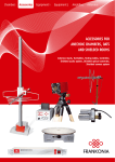
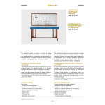
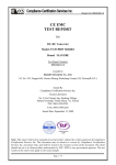
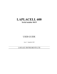
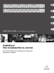
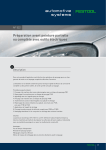
Chambers
Accessories
Equipment 1
Equipment 2
Amplifiers
Antennas
EMC TEST EQUIPMENT
PART 2
RF-Relay Switching Unit, Electric Field Strength Meter,
RF-Power Meter, Striplines, GTEM-Cells, TEM-Cells
Content / Index
PAGE // 2
EMC TEST INSTRUMENTS:
Electric Field Strength Meter, 10 kHz - 9.25 kHz EFS-10 / EFS-100
3-4
RF-Power Meter, 10 kHz - 6 GHz PMS-1084
5
RF-Relay Switching Unit, DC - 12.4 GHz optional: DC - 18 GHz, DC - 40 GHz
RSU
6
GTEM-Cells, 100 kHz - 18 GHz GTEM 250 - GTEM 2000
7-12
Striplines, 50 Ω / 90 Ω SR 50/1000, SR 90/1000
13
Open TEM-Cells TEM 220 – TEM 3000
14
Closed TEM-Cells TEMF 200 – TEMF 3000
15
EFS-10 / EFS-100 Field Strength Meter
for field strength measurements during radiated immunity tests acc. to IEC/EN 61000-4-3 / -20
Special features
·
·
·
·
·
·
Extreme small size
PC connection via fibre optic link
Excellent isotropy (0.3 dB typical)
Frequency range: 10 kHz to 9.25 GHz
Field strength measurements from 0.14 V/m to 500 V/m
Up to 80 hours operating time before recharging
General description:
The Frankonia EFS field strength meters especially have been designed
for field strength measurements / field homogeneity measurements
during radiated immunity tests according to IEC/EN 61000-4-3 / -20.
But it could also be used to measure the radiation exposure of the
environment, for example at workplaces or flats.
The EFS is an isotropic miniature E-field sensor to ensure that the
E-field will not be influenced by the size of the sensor itself. It even
does not need any metering unit (which could also influence the field
strength), because of its direct fibre optic output which allows direct
connection of the sensor to the USB-interface of the control PC or
laptop. The measuring values may be displayed via the individual
IEC/EN 61000-4-3 / -20 control software or via a Windows software
included in the delivery.
The EFS-10 / EFS-100 cover the frequency range from 10 kHz up to
9.25 GHz and are able to detect electrical field strength in the range
from 0.14 V/m to 500 V/m (depending on type).
The sensors are battery operated by Li-Mn batteries, which allow a
maximum operation time of 80 hours before recharging.
3 // PAGE
EFS-10 / EFS-100 Field Strength Meter
for field strength measurements during radiated immunity tests acc. IEC/EN 61000-4-3 / -20
Technical specifications
Frequency range
EFS-10
EFS-100
10 kHz - 9.25 GHz
100 kHz - 9.25 GHz
Flatness
0.1 – 150 MHz:
0.4 dB
1 – 150 MHz:
0.8 dB
With frequency correction OFF
0.05 – 6 GHz:
1.6 dB
0.5 – 6 GHz:
1.6 dB
0.03 – 7.5 GHz:
3.2 dB
0.3 – 7.5 GHz:
3.2 dB
0.05 – 7.5 GHz:
0.4 dB
0.3 – 7.5 GHz:
0.4 dB
With frequency correction ON
Dynamic range (single range)
Linearity
0.5 – 500 V/m (60 dB)
0.14 – 140 V/m (60 dB)
0.4 dB @ 50 MHz / 1-500 V/m
0.4 dB @ 50 MHz / 0.3 – 100 V/m
0.01 V/m
Resolution
6 monopoles
Sensors
Isotropicity
Overload
Measured data X-Y-Z axis
Sampling rate
Digital filter
0.5 dB (0.3 dB typical) (@ 50 MHz)
1000 V/m
300 V/m
sampling simultaneous on X-Y-Z axis
22 S/s to 0.03 S/s, depending on filter setting
2.3 to 28 Hz, low-pass, pre-settable
Internal battery
3 V - 5 mAh, rechargeable Li-Mn
Operation time
80 hours @ 0.4 S/sec., 28 Hz filter
60 hours @ 5 S/sec., 28 Hz filter
Recharging time
Internal data memory
Communication
Fibre optic connector
Fibre optic length
Fibre optic to PC connection
PC Software
48 hours for full operation time
serial number, calibration date, calibration factors, firmware version
bidirectional fibre optic link
HFBR-0500
10 m standard (20/40 m optional)
fibre optic to RS232 converter, RS232 to USB converter
included (display of field, temperature and battery voltage measurements,
setting of filters, sampling rate, frequency)
Operating temperature
-10 °C ÷ +50 °C
Temperature reading
0.1 °C resolution
Battery voltage reading
10 mV resolution
Dimensions
Weight
Probe mount
Included accessories
53 mm overall, (body: 17 mm diameter, sensor: 17 mm)
25 g, including 1 m fibre optic pigtail
20 UNC female
10 m fibre optic cable, optical/RS232 adapter + RS232/USB adapter,
software, battery charger
Optional accessories
20 m fibre optic cable, order-no.: EFS-OF20
PAGE // 4
40 m fibre optic cable, order-no.: EFS-OF40
2/4-Channel RF-Power Meter – PMS 1084
10 kHz to 6 GHz
Description
The PMS 1084 is in the standard version a 2-channel RF-Power Meter
for the frequency range from 100 kHz up to 6 GHz or from 10 kHz to
500 MHz (PMS 1084 B). The measuring range reaches from –60 dBm
to +20 dBm. It is possible to upgrade the PMS 1084 up to max. 4 measuring channels at any time. The measured values can be displayed via
a software which is included in the delivery or via the control software
Technical specifications
of an automated test system. For the integration of the PMS 1084 into
a remote-controlled test system it is equipped with serial and USB
interface. Hence the PMS 1084 is very good suitable for the automated
measurement of forward and reverse power in immunity test systems
acc. to IEC/EN 61000-4-3 / -6. It is available for the installation into
19”-rack or as stand-alone unit.
PMS 1084
Number of channels
PMS 1084B
2 (standard); up to 4 (option)
Frequency range 2 x Input-Module LF
Frequency range 2 x Input-Module HF
Measuring range
10 kHz - 500 MHz
100 kHz - 6 GHz
-60 dBm to +20 dBm (10 kHz ≤ f ≤ 4 GHz)
-45 dBm to +20 dBm (4 GHz < f ≤ 6 GHz)
Accuracy
Resolution
± 1 dB (0.5 dB typical)
0.1 dB
Integration time
0.5 – 200 ms (firmware)
Max. input level
+27 dBm (= 500 mW)
VSWR
1.15
RF-Impedance
50 Ω
Interface (PC)
USB, RS232 (9-pol Sub D. female)
Input
N-type female connector
Dimensions (D x W x H)
172 x 482.6 x 44.3 mm
Weight
Power supply
Accessories included
approx. 2.5 kg
115/230 V
Power cord, USB cable, application software, user manual
Options
Expansion of 1 measuring channel (max. up to 4 channels); 100 kHz to 6 GHz
PMS-CHAB
Expansion of 1 measuring channel (max. up to 4 channels); 10 kHz to 500 MHz
5 // PAGE
PMS-CHA
RF-Relay Switching Unit - RSU
DC…12.4 GHz (up to 40 GHz optional)
Main characteristics:
·
·
·
·
·
·
Up to 4 pcs. Coax-Relays
1 input to 2 or 3 outputs
Manual or remote-controlled
USB, RS232 and GPIB interface
Easy integration in test systems
For RF- and EMC testing
Description
The RSU Relay Switching Unit is applicable for all fields of RF- and EMC measurements to
switch (manual or remote-controlled) from one input to 2 or 3 outputs. Typical applications
in measuring systems are changeover switching between different amplifiers, antennas or
power meters. This does also prevent circuit faults due to wrong cabling. By means of a
selector switch on the front panel of the RSU it is possible to work in manual mode or remotecontrol mode via the RS232, USB or GPIB interface. The input/output connectors of the relays
are installed on the rear panel of the RSU, this allows an easy cabling when or where the
RSU is mounted into a 19”-rack. A RSU can be equipped with a maximum of 4 relays with 2
or 3 outputs. The quantity of relays with 2 or respectively 3 outputs is variable. The delivery
includes a Windows software for easy remote-controlled applications. However for extensive
systems it is recommended to integrate the RSU driver into the system control software. The
easy to follow commands for RS232 and GPIB interfaces are listed in the user manual.
RSU
X2
X3
Quantity of relays
with 2 outputs
Quantity of relays
with 3 outputs
RSU 2223 = 2 relays with 2 outputs
and 2 relays with 3 outputs
RSU
Technical specifications
Frequency range
DC to 12.4 GHz (up to 40 GHz optional)
DC...1 GHz
1 GHz...5 GHz
5 GHz...10 GHz
10 GHz...12.4 GHz
VSWR
≤ 1.04
≤ 1.14
≤ 1.3
≤ 1.5
Isolation
≥ 90 dB
≥ 80 dB
≥ 70 dB
≥70 dB
Insertion loss
≤ 0.05 dB
≤ 0.1 dB
≤ 0.2 dB
≤ 0.3 dB
Max. power input
≤ 1.00 kW
≤ 0.44 kW
≤ 0.31 kW
≤ 0.28 kW
Impedance
50 Ω
RF-connectors / Relays
N-female
Switching time
≤ 60 ms
Number of operations
Max. 10/Minute
Operating temperature
+10 ºC ... +40 ºC
Max. humidity
PAGE // 6
Definition of the relay assambly:
< 90 %
Cabinet
19”-subrack or desktop case
Dimensions (D x W x H)
435.5 x 448.9 x 132.55 mm
Weight
7.6 kg
GTEM-Cells acc. to IEC/EN 61000-4-20
Septum-height: 250 mm to 2000 mm / 0.1 MHz to 18 GHz
Description
The GTEM-cell is a TEM waveguide with the upper frequency limit
extended to the GHz range. It is a low-cost alternative measurement
facility for both radiated emission and immunity measurements. It is
included in the published standard IEC/EN 61000-4-20 “Emission and
Immunity Testing in Transverse Electromagnetic (TEM) Waveguides”.
Compared to other measuring methods like EMC test in anechoic chambers or OATS (Open Area Test Sites), GTEM-cells offer some significant
advantages for the testing of small and medium sized EUT´s (Equipment
Under Test) up to a frequency range of 18 GHz. Quick turnarounds of
the EUT as well as numerous testing variations are easy and fast to
handle. Switching from emission to immunity testing requires only
simple adjustments from receiver input to amplifier output. You are
irrespective of long waiting times associated with off-site test labs or
weather and ambient delays that can occur at OATS facilities. Whether
you are at the design qualification, pre-compliance, compliance, or
production sampling stage, the GTEM is the right choice for you.
Calculation of the required forward power for radiated immunity tests:
Example:
P = (E x h)2 /R x flatness factor (2) x modulation factor (3.24 for 80 %AM)
E= required field strength; h=septum height in meter; R= input impedance 50 Ω
Field strength 10 V/m, 80 %AM with GTEM 1000:
P= (10 x 1.0 m)2 /50 x 2 x 3.24 = 12.96 W
7 // PAGE
GTEM test set-up for radiated immunity
tests and emission measurements:
PC
USB / LAN / GPIB
Immunity Software CR-LAB
Emission Software incl. cable
kit and rack installation
EMI Receiver
GPIB
Field Strength Meter
USB / RS232
EFS
PAGE // 8
GTEM 1000
incl. options + camera FMC
GTEM test set-up for radiated immunity
tests and emission measurements:
USB / LAN / GPIB
Controller
Board
SP3T
Antenna 3
Antenna 2
Antenna 1
SP3T
2x EUT fail
2x Analog in
EMI Receiver 1
EMI Receiver 2
RF-Power Meter
DC
1
DC
2
DC
3
DC
4
SP4T
Voltmeter IN
Amplifier 1
Amplifier 2
FLL/FLH/FLG
SP4T
FLL/FLH/FLG
Signal
Generator
3 GHz / 6 GHz
Relay-Switching
Unit
ECU-3/-6
Amplifier 3
FLL/FLH/FLG
FLL/FLH/FLG
9 // PAGE
Amplifier 4
GTEM-Cells acc. to IEC/EN 61000-4-20
Technical specifications
250
400
500
750
1000
Input connector
N
N
N
N
N
Nominal impedance
50
50
50
50
50
0.01 MHz-18 GHz*
0.01 MHz-18 GHz*
0.01 MHz-18 GHz*
0.01 MHz-18 GHz*
0.01 MHz-18 GHz*
Electrical Data
Frequency range
Typical VSWR
Typical VSWR at critical frequency
Max. input power, W continuous*/pulsed
1:1.2
1:1.2
1:1.2
1:1.2
1:1.2
≤ 1:1.6
≤ 1:1.6
≤ 1:1.6
≤ 1:1.6
≤ 1:1.6
500*/1 Kw
500*/1 Kw
500*/1 Kw
700*/1.5 Kw
700*/1.5 Kw
Fix/CEE
Fix/CEE
Fix/CEE
Fix/CEE
Fix/CEE
-
-
-
-
Electrical Equipment / Options
Mains connectors
Input socket plug 10Aac
Input socket plug 16Aac
Output socket tape 16Aac
Additional sockets for EUT
Ground connection M6
AC filter 6 A / 3 wires
AC filter 10 A / 3 wires
AC filter 16 A / 5 wires
AC filter 30 A / 5 wires
AC filter 64 A / 5 wires
Electrical safety interlock
Indoor lighting 50 W
9-poles signal filter (DB9)
25-poles signal filter (DB25)
Channel for fibre optic leads (3 couple)
RF feed-thru connectors N Type
1
1
1
1
1
RF feed-thru connectors SMA Type
2
2
2
2
2
-
-
-
Mechanical Equipment / Options
Second small door close to input
Window in door, 20 cm Ø
Gas / Water feed-thru plates
Honeycomb panel
Fans N.4 12x12 cm
-
Empty technical panels
-
-
1
3
3
115x64x44
220x122x83
300x168x115
400x220x150
500x271x188
30x23
40x40
40x40
61x61
80x90**
Mechanical Dimensions / Max. EUT size
Outer (LxWxH), cm
PAGE // 10
Door (WxH), cm
Wheeled undercarriage
-
Weight kg approx.
24
60
200
400
600
Max. test volume (LxWxH), cm
20x20x15
35x40x25
40x40x30
60x60x50
75x75x70
Defined test vol. ± 3 dB < 1000 MHz (LxWxH), cm
15x15x10
25x30x13
30x35x17
45x45x25
60x60x30
250 mm
400 mm
500 mm
750 mm
1000 mm
Septum height
** Other sizes are available on request
*6 GHz standard, 18 GHz optional
Standard
Costed option
- Not provided
GTEM-Cells acc. to IEC/EN 61000-4-20
Technical specifications
1250
1500
1750
2000
Input connector
N
N
N
N
Nominal impedance
50
50
50
50
0.01 MHz-18 GHz*
0.01 MHz-18 GHz*
0.01 MHz-18 GHz*
0.01 MHz-18 GHz*
Electrical Data
Frequency range
Typical VSWR
1:1.2
1:1.2
1:1.2
1:1.2
≤ 1:1.6
≤ 1:1.6
≤ 1:1.6
≤ 1:1.6
500/1000*
600/1200*
800/1400*
1000/1600*
Fix/CEE
Fix/CEE
Fix/CEE
Fix/CEE
RF feed-thru connectors N Type
1
1
1
1
RF feed-thru connectors SMA Type
2
2
2
2
-
1
3
3
600x306x252
700x358x255
800x410x290
900x462x324
80x110**
80x120**
80x130**
80x140**
850
1000
1300
1650
Max. test volume (LxWxH), cm
95x95x85
120x120x100
140x140x60
175x175x70
Defined test vol. ± 3 dB < 1000 MHz, LxWxH, cm
75x75x42
100x100x50
125x125x58
150x150x65
Septum height
1250 mm
1500 mm
1750 mm
2000 mm
Typical VSWR at critical frequency
Max. input power, W continuous/pulsed*
Electrical Equipment / Options
Mains connectors
Input socket plug 16Aac
Output socket tape 16Aac
Additional sockets for EUT
Ground connection M6
AC filter 10 A / 3 wires
AC filter 16 A / 5 wires
AC filter 30 A / 5 wires
AC filter 64 A / 5 wires
Electrical safety interlock
Indoor lighting 50W
9-pole signal filter (DB9)
25-pole signal filter (DB25)
Channels for fibre optic leads (3 couple)
Mechanical Equipment / Options
Second small door close to input
Window in door, 20 cm Ø
-
Gas / Water feed-thru plates
Honeycomb panel
Fans N.4 12x12 cm
Empty technical panels
High power termination
Mechanical Dimensions / Max. EUT size
Outer (LxWxH), cm
Door (WxH), cm
Wheeled undercarriage
Weight kg approx.
*6 GHz standard, 18 GHz optional
Standard
Costed option
- Not provided
11 // PAGE
** Other sizes are available on request
GTEM-Cells acc. to IEC/EN 61000-4-20
Type
I/0 ports
GTEMs MODEL
250-400
GTEM-B01
EIA 7/8" Flange input connector (up to 3 GHz)
GTEM-B02
7/16" Input connector (up to 3 GHz)
GTEM-B03
1 Kw max. input power, (up to 3 GHz) (the max. input power is
limited by the spec. of the max input power of the selected GTEM)
GTEM-B04
Upgrade input power 1.6 Kw, (up to 3 GHz) (the max. input power is
limited by the spec. of the max input power of the selected GTEM)
GTEM-B05
Channels for fibre optical feed-thru (additional 3 pairs)
GTEM-B06
Additional RF feed-thru connectors N type
GTEM-B07
Additional RF feed-thru connectors SMA type
500-750-1000-1250
1500-1750-2000
-
Electrical Equipment / Options
GTEM-B08
Additional socket for EUT
GTEM-B09
Internal illumination (halogene, 50 W)
GTEM-B10
AC filter 16 A / 5 wires
GTEM-B11
AC filter 30 A / 5 wires
-
GTEM-B12
AC filter 64 A / 5 wires
-
GTEM-B13
Electrical safety interlock
GTEM-B25
9-pole DB9 signal EMI filter
GTEM-B14
25-pole DB25 signal EMI filter
GTEM-B26
RJ11 (RJ9) feed-thru connector
GTEM-B32
RJ45 feed-thru connector
Mechanical Equipment / Options
GTEM-B15
Second door close to input
-
GTEM-B16
Window in door, Ø 200 mm
GTEM-B17
Gas / water-feed-thru plates
GTEM-B18
Honeycomb panel
-
GTEM-B19
Fan kit for GTEM on technical panel
-
GTEM-B20
Door for tests acc. to SAE J1752/3
GTEM-B21
Wheeled undercarriage
GTEM-B23
Vertical positioning, turn of door position, plastic table over pyramids
GTEM-B27
Empty installation panel, Ø 200 mm
GTEM-B28
Fan kit incl. channel for heat sink
-
PAGE // 12
Standard
Costed option
- Not provided
acc. to ISO 11452-5
50 Ω Stripline for Immunity Tests - SR 50/1000
90 Ω Stripline for Immunity Tests - SR 90/1000
Description
This stripline is designed for immunity tests on automotive devices
according to ISO 11452-5. The stripline is fixed on a table and
easy to move. The table can be sloped vertically in order to reduce
the width. It is also possible to divide the stripline very easy in two
Technical specifications
parts for storage or during transport (50 Ω version). It is the only
stripline on the market with the ability to carry out test up to 1 GHz
with excellent return loss. The stripline is available with 50 Ω or
90 Ω impedance.
SR 90/1000
Frequency range
0 to 1 GHz
0 to 1 GHz
Max. input power
1 kW continuous
>200 W continuous
(>100 W with impdedance adapter)
Wave impedance
377 Ω
377 Ω
50 Ω ± < 5 Ω
90 Ω ± < 6 Ω
VSWR
better than 1.22
<1.92
Return loss
better than 20 dB
>10 dB up to 1 GHz
N 50 Ω
N 75 Ω
Height of the plate
15 cm over ground plane
15 cm over ground plane
Height of the table
95 cm
80 cm
430 x 150 x 105 cm (service position)
2 * 215 x 85 x 165 cm (storage)
350 x 90 x 95 cm
Weight
approx. 140 kg
approx. 100 kg
Options
Filter box
Impedance adapter 50-90 Ω
Impedance
Connector type
Size (L x W x H)
Filter box
Other height under plate
13 // PAGE
SR 50/1000
Open TEM-Cells
Description
These open TEM-cells are well suited for immunity testing of small
objects according to European (CE) and automotive standards
(SAE J1113-25) or for biological experiments. The advantage of these
TEM-cells is that they are open and it is very easy to control the functions of the EUT (Equipment Under Test). The applications are for
instance the immunity testing of watches, pagers, telephones or PCB’s.
Technical specifications
TEM 220
TEM 500
TEM 1000 *
TEM 3000 *
DC - 220 MHz
DC - 500 MHz
DC - 1 GHz
DC - 3 GHz
Height under plate
33.3 cm
14.7 cm
7.3 cm
2.5 cm
Max. input power
1.5 kW
1 kW
750 W
400 W
Maximum field
800 V/m
1.5 kV/m
2.6 kV/m
5.6 kV/m
Field for a 25 W amplifier
105 V/m
215 V/m
480 V/m
1400 V/m
180 x 160 x 73 cm
97 x 81 x 32cm
54 x 45 x 16.8 cm
44 x 18 x 8 cm
55 kg
12 kg
3.5 kg
1.1 kg
Frequency range
Dimensions (LxWxH)
Weight
Field precision
Connector
PAGE // 14
In comparison with other closed TEM-cells, the price is low. The
field decreases rapidly outside the open TEM-cells (approx. 33 dB at
1 meter) and it is therefore possible to use an open TEM-cell in ordinary
facilities. Another interesting application is the calibration of field
probes as the generated field inside the TEM-cell is very exact.
TEM-cells are the most precise structures for field calibrations.
±5%
type N 50 Ω
Cell impedance
50 Ω
Wave impedance
377 Ω
VSWR
< 1.2 (<1.9 for the TEM3000)
Options
Signal and power supply filters
* Can be equipped with a test setup for IC or PCB acc. to SAE J1752-3
Other models are available on request
Closed TEM-Cells
Description
The closed TEM-cells TEMF 200 and TEMF 500 are specially designed for
immunity tests on automotive devices according to ISO 11452-3 and
to SAE J1113-24. The TEMF 1000 and TEMF 3000 allow immunity tests
on small devices and require a low power amplifier. Therefore the test
installation is much cheaper compared to an absorber room with antennas. The TEM (Transverse Electro-Magnetic) mode is the only mode
produced in the cell below the cut-off frequency. The electric field is
Technical specifications
vertical, the magnetic field horizontal and the wave impedance 377 Ω.
The field conditions inside the cell are similar to far field conditions.
An optional filter box can be placed behind the cell for power and
signal line connections. For automotive tests the recommended minimum amplifier power is 100 W (TEMF 200) and 50 W (TEMF 500).
It is also possible to use the cell for radiation measurements under
certain conditions.
TEMF 200
TEMF 500
TEMF 1000 *
TEMF 3000 *
DC - 200 MHz
DC - 500 MHz
DC - 1 GHz
DC - 3 GHz
30 cm
10 cm
7.3 cm
2.35 cm
Dimensions (LxWxH)
130 x 70 x 62 cm
60 x 30 x 22 cm
54 x 45 x 18 cm
15 x 8 x 6 cm
Max. input power
1.6 kW long term
1 kW long term
750 W long term
400 W long term
118 V/m
350 V/m
475 V/m
1.4 kV/m
50 Ω ± 5 Ω
50 Ω ± 5 Ω
50 Ω ± 7 Ω
50 Ω ± 7 Ω
< 1.1
< 1.1
< 1.2
< 1.2
Return loss
> 25 dB
> 25 dB
> 20 dB
> 20 dB
Connector type
N 50 Ω
N 50 Ω
N 50 Ω
N or SMA 50 Ω
approx. 29 kg
approx. 20 kg
approx. 4.8 kg
approx. 1.6 kg
Frequency range
Height under the plate
Field for a 25 W amplifier
Impedance
VSWR
Weight
Signal and power supply filters
* Can be equipped with a test setup for IC or PCB acc. to SAE J1752-3
Other models are available on request
15 // PAGE
Options
Copyright © by Frankonia EMC Test-Systems GmbH, 10-2011 / English Version 2.0
Frankonia EMC Test-Systems GmbH
Daimlerstraße 17, 91301 Forchheim
Germany
Frankonia GmbH
Industriestraße 16, 91180 Heideck
Germany
Web. www.frankonia-emv.com
Mail. [email protected]
Web. www.frankoniagroup.com
Tel.
Fax.
+49 (0) 91 91 / 73 666 - 0
+49 (0) 91 91 / 73 666 - 20