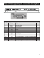
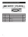
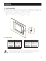
1
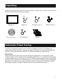
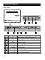
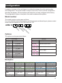
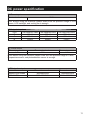
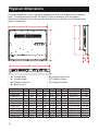
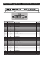
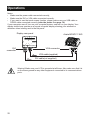
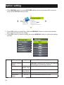
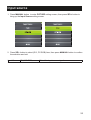
Talk to us. We listen.
Industrial Panel Mount LCD Display
Thank you for purchasing the ADM 1800 series Industrial Panel Mount
LCD Display. We are confident that you will be pleased with the
performance and reliability of your new display. The display was designed
to meet the screen performance requirements of today's demanding
industrial applications. While complying with a wide variety of industrial
video formats, it delivers a larger screen area, higher resolutions, and
greater color accuracy than many displays in its price range.
uSER mANUAL
ADM-1800 Series
Version 1.3
contents
Product safety precautions .......................................................................................... 4
FCC declaration of conformity ..................................................................................... 5
Copyright 2001 ........................................................................................................ 5
Features.......................................................................................................................... 6
Applications ................................................................................................................... 6
Unpacking ...................................................................................................................... 7
Automatic Power Saving .............................................................................................. 7
Product Overview .......................................................................................................... 8
Rear panel............................................................................................................... 8
Configuration ................................................................................................................. 9
Model number ......................................................................................................... 9
Options .................................................................................................................... 9
Panel spectifications ..................................................................................................... 10
Ratings ........................................................................................................................... 10
Optional Touch screen ................................................................................................. 10
DC power specification ................................................................................................. 11
Physical dimensions .................................................................................................... 12
Connectors ................................................................................................................... 13
LCD Terminals ............................................................................................................... 13
Pins in DVI signal input connector description .......................................................... 14
Pins in VGA signal input connector description ........................................................ 15
Pins in touch connector description ........................................................................... 16
Installing ......................................................................................................................... 17
1. Panel mounting ................................................................................................. 17
2. Cutout size ......................................................................................................... 17
Connecting the display ................................................................................................. 18
1.Connect the display via VGA or DVI .................................................................... 18
2.Connect the display via USB cable or RS 232 cable ........................................... 19
3.Connect power adapter and cable ....................................................................... 19
Installing calibration software ...................................................................................... 20
Video alignment or calibration ..................................................................................... 21
Operations ..................................................................................................................... 22
Picture setting................................................................................................................ 23
Option setting ................................................................................................................ 24
Input source ................................................................................................................... 25
Maintenance and troubleshooting ............................................................................... 26
1. Maintenance........................................................................................................ 26
2. Troubleshooting................................................................................................... 26
3. Product Limited Warranty .................................................................................... 27
4. Technical Support................................................................................................ 27
5. RMA Procedures ................................................................................................. 28
6. RMA Credit Policy ............................................................................................... 28
7. RMA Transportation Policy .................................................................................. 29
8. RMA Shipping Instruction .................................................................................... 29
9. Arista’s Limited Liability ....................................................................................... 30
10.Disclaimer .......................................................................................................... 30
Frequently asked questions ......................................................................................... 31
3
Product safety precautions
Read all of these instructions and save this manual for later use. Follow all warnings and
instructions on the product.
• Relative humidity: 25%~80%
• Storage temperature: -20oC to 60oC(-4F to 140F)
• Operation temperature: 0~50oC(32F to 122F)
• Do not cover or block the ventilation holes in the enclosure.
• Do not insert sharp objects or spill liquid into the display through the cabinet slots. This
may cause accidental fire, electric shock or failure.
• Unplug the unit when not in use for an extended period of time.
• Consult a service technician if the display does not operate normally when you have
followed the instructions in this manual.
• Do not attempt to repair this product yourself, always get a qualified service agent carry
out adjustments or repairs.
• Do not place heavy objects on the unit.
• Use only the power cord supplied with the unit. In case you use another power cord,
make sure that it is certified by the applicable national standards if not being provided
by the supplier. If the power cable is faulty in any way, please contact the manufacturer
or the nearest authorized repair service provider for a replacement.
• The power supply cord is used as the main disconnect device. Ensure that the socket
outlet is easily accessible after installation.
• Overloaded AC outlets and extension cords are dangerous. So are frayed power
cords and broken plugs. They may result in a shock or fire hazard. Call your service
technician for replacement.
• Hands must be dry when holding the power plug to avoid an electric shock. Do not
damage the power cord by disassembling, bending, pulling or heating up. It can cause
fire or electric shock.
• Make sure to completely insert the power plug. Insecure connections can cause fire.
• Unplug the display if you need to clean it with a slightly damp cloth. The screen may be
wiped with a dry cloth when the power is off. However, never use alcohol, solvents or
ammonia-based liquids.
• Remove any object that could fall into the vents or prevent proper cooling of the
display’s electronics.
• Do not subject the LCD display to severe vibration or high impact conditions.
• Do not place the LCD display in the trunk of a car.
This mark is applied to show the equipment conforms to European safety and
electro-magnetic compatibility standards.
4
FCC declaration of conformity
Note: This equipment has been tested and found to comply with the limits for a Class B
digital device, pursuant to Part 15 of the FCC Rules. These limits are designed
to provide reasonable protection against harmful interference in a residential
installation. This equipment generates,uses, and can radiate radio frequency
energy and, if not installed and used in accordance with the instructions, may cause
harmful interference to radio communications. However, there is no guarantee that
interference will not occur in a particular installation. If this equipment does cause
harmful interference to radio or television reception, which can be determined by
turning the equipment off and on the user is encouraged to try and correct the
interference by one or more of the following measures:
- Reorient or locate the receiving antenna.
- Increase the separation between the equipment and receiver
- Connect the equipment into an outlet on a circuit different from that to which the receiver
is connected
- Consult the dealer or an experienced radio/TV technician for help
DECLARATION OF CONFORMITY
We (Arista Corporation),
40675 Encyclopedia Circle,
Fremont, CA 94538 U.S.A.
510-226-1800
declare under our sole responsibility that the product(s)
(ADM-1815BP)
complies(y) with Part 15 of FCC Rules.
Operation is subject to the following two conditions: (1) this device may not cause
harmful interference, and (2) this device mustaccept any interference received, including interference that may cause undesired operation.
© Copyright 2001
The information contained in this user’s manual and all accompanying documentation
is copyrighted and all rights are reserved. This publication may not, in whole or in part,
be reproduced, transcribed, stored in a retrieval system, translated into any language or
computer language, or transmitted in any form whatsoever without the prior written consent
from the manufacturer, except for copies retained by the purchasers for their personal
archival purposes. The manufacturer reserves the right to revise this user’s manual and
all accompanying documentation and to make changes in the content without obligation to
notify any person or organization of the revision or change.
IN NO EVENT WILL THE VENDOR BE LIABLE FOR DIRECT, INDI-RECT, SPECIAL,
INCIDENTAL, OR CONSEQUENTIAL DAMAGES ARIS-ING OUT OF THE USE OR
INABILITY TO USE THIS PRODUCT OR DOCUMENTATION, EVEN IF ADVISED OF
THE POSSIBILITY OF SUCH DAM-AGES. IN PARTICULAR, THE VENDOR SHALL NOT
HAVE LIABILITY FOR ANY HARDWARE, SOFTWARE, OR DATA STORED OR USED
WITH THE PRODUCT, INCLUDING THE COSTS OF REPAIRING, REPLACING,OR
RECOVERING SUCH HARDWARE, SOFTWARE, OR DATA.
All trademarks mentioned in this document are acknowledged. The specifications in this
manual are subject to change without notice.
5
Features
• 6”, 8”,10”, 12“, 15”, 17”, 18”, 19”, 20”, 21”, or 24” XGA color TFT LCD display.
• Support Vertical refresh rate up to 75Hz for VGA, SVGA and XGA of VESA standard
specification.
• The Best Productivity Solution
• True XGA with expansion support from DOS, VGA, SVGA.
• Analog RGB signal direct input offers multiscan function.
• Color supports up to 8 bits per color, total 16.7 million colors.
• D-SUB15 Analog RGB connector.
• Strengthen Anti-Reflective Protective Faceplate Optional
• Sun Light Readable Option
• High Brightness and Contrast
• Wide Viewing Angle
• Strengthened glass protects LCD panel from shock damage.
• Single control operated and transparent On-Screen-Display (OSD) user interface. Full
control of all relevant display and interface parameters via OSD.
• OSD (On Screen Display) buttons on the rear panel.
• Touch Screen: Resistive, Capacitive and SAW Option
• Easy plug and play DVI ensures true digital experience
• Embedded power supply eliminates external power adapters
Applications
The product covered herein are designed and manufactured for following application areas.
• Office electronics
• Instrumentation and measuring equipment
• Machine tools
• Audiovisual equipment
• Home appliances
• Communication equipment other than trunk lines
• Do not use the products covered herein for the following equipment that demands
extremely high performance in terms of functionality, reliability, or accuracy.
• Aerospace equipment
• Communication equipment for trunk lines
• The board is not user serviceable or repairable. Warranty does not cover user error in
connecting up to the controller and is invalidated by unauthorized modification or repairs.
6
Unpacking
Unpack the package and inspect the items closely to make sure no item is damaged and
all items listed are present in your package:
Display x1
Adaptor x1
AC power cord x1
Drive CD rom x1
VGA cables x1
Screws
RS232 cable x1
Automatic Power Saving
If you have compliance display card or software installed in your PC, the display can
automatically reduce its power consumption when not in use. If an input from a keyboard,
mouse or other input device is detected, the display will 'wake up' automatically.
IMPORTANT:
Always activate a screen saver program during your application. If a still image in high
contrast remains on the screen for an extended period of time, it may leave an ‘after-image’
or ‘ghost image’ on front of the screen. This is a well-known phenomenon that is caused by
the shortcomings inherent in LCD technology. In most cases, the after-image will disappear
gradually over a period of time after the power has been switched off. Be aware, that the
after-image symptom cannot be repaired and is not covered under warranty.
7
Product Overview
Rear panel
1
5
No.
6
9
3
4
10
Function
Use for selecting options or decrease the data
MENU
Use for setup OSD settings or confirm some operations.
Use for selecting options or increase the data
3
8
8
Button
1
2
7
2
4
POWER
Power On/Off control
5
24V DC jack
24V DC power input
6
DVI jack
DVI source input
7
VGA jack
VGA source input
8
12V DC Input
12V DC power input
9
Touch connector RS232 Touch screen connector
10
Touch connector USB touch screen connector
Configuration
Located on the back of the unit chassis is a sticker that shows the unit’s serial number
and configuration. The serial number is unique to the unit of course, but the configuration
describes the display, CPU and options with which the unit was configured at the factory.
The configuration is given in two parts: the model number and the options.
Model number
The model number can be parse as follow:
For more detailed technical information, including jumpers and board layout, please contact
Arista customer support at (510) 226-1800, ext. 137
ADM-18
pu
ns
io
e
pt
m
O
he
Sc
g
in
u t al
o o ign
tS
M
In
D
LC
ze
Si
Options
The options can be parsed as follows:
6
8
10
12
15
17
18
19
20
21
24
LCD Size
6.5 Inch
8.4 Inch
10.4 Inch
12.1 Inch
15 Inch
17 Inch
18.5 Inch
19 Inch
20.1 Inch
21.5 Inch
24 Inch
xxx
Z xx
xx4, xx5,
or Zx4, Zx5
xx0, xx1,
or Zx0, Zx1
xx0, xx4,
or Zx0, Zx4
xx1, xx5
or Zx1, Zx5
Options
5-wire resistive touch screen
No touch
Stainless steel bezel
Black color bezel
24VDC input
110/220VAC input
Examples:
Panel Mount
Touch Screen
Bezel
Power Supply
Panel Mount
Touch Screen
Bezel
ADM-1817AP-000
5-Wire Resistive
Black Color Bezel
24VDC Input
ADM-1817AP-004
5-Wire Resistive
Stainless Steel
Bezel
Power Supply 24VDC Input
ADM-1817AP-001
5-Wire Resistive
Black Color Bezel
110/220VAC Input
ADM-1817AP-005
5-Wire Resistive
Stainless Steel
Bezel
110/220VAC Input
ADM-1817AP-Z00
No Touch
Black Color Bezel
24VDC Input
ADM-1817AP-Z04
No Touch
Stainless Steel
Bezel
24VDC Input
ADM-1817AP-Z01
No Touch
Black Color Bezel
110/220VAC Input
ADM-1817AP-Z05
No Touch
Stainless Steel
Bezel
110/220VAC Input
9
Panel spectifications
Model
Number
ADM-1806
ADM-1808
ADM-1810
ADM-1812
Display Type
Resolution
Colors Dot Size (mm)
6.5 Inch TFT
8.0 Inch TFT
10.4 Inch TFT
12.1 Inch TFT
16.7M
16.7M
16.7M
16.7M
ADM-1815
ADM-1817
ADM-1818
ADM-1819
ADM-1820
ADM-1821
ADM-1824
15.0 Inch TFT
17.0 Inch TFT
18.5 Inch TFT
19.0 Inch TFT
20.1 Inch TFT
21.5 Inch TFT
24 Inch TFT
640 x 480
800 x 600
800 x 600
800 x 600
(1024x768)
1024x768
1820x1024
1366 x 768
1280 x 1024
1600 x1200
1920 X 1080
1920 x 1080
Luminance Contrast Viewing
Angle (V/H)
0.207 X 0.207 500
700
1400/1600
0.213 X 0.213 450
600
1500/1500
0.264 x 0.264 400
700
1200/1600
0.3075 x 0.3075 450
700
1300/1600
16.7M
16.7M
16.7M
16.7M
16.7M
16.7M
16.7M
0.297 x 0.297
0.264 x 0.264
0.3 X 0.3
0.294 x 0.294
0.255 x 0.255
0.3075 x 0.3075
0.277 x 0.277
400
350
250
400
300
250
250
700
1000
1000
1000
800
3000
5000
1200/1600
1600/1700
1700/1600
1600/1700
1780/1780
1600/1700
1780/1780
Ratings
Front Bezel Color
NEMA Rating
Mounting
Display Control
Operation
Temperature
Storage
Temperature
Storage
Humidity
Altitude
Vibration
Shock
Enclosure rating
Black color Powder
Front bezel meets NEMA 4/4X requirements
Panel/VESA Mount/Rack mount
Rear or Front OSD Control Buttons
32 to 122 F (0 to 50 C)
-4 to 140 F (-20 to 60 C)
10 to 95% @ 104 F (40 C), non-condensing
10,000ft (3000 meters)
5Hz to 500Hz, 1G without rotating media
10G peak acceleration, 11 m sec without rotating media
NEMA 4 and IP65 compliant, when properly installed in a rated enclosure
Optional Touch screen
Type: 5-wire, analog resistive
Response Time: <10ms
Accuracy: ± 2.03 mm
Resolution: 4096 x 4096
Light transmission: Up to 78%
Lifetime: Over 35 million touches
MTBF: 490,000 hours
Operating pressure: Less than 4 ounces
Chemical Resistance: Tested with acetone, ethylene, isopropy1 alcohol and ammonia
Controller: RS-232 or USB interface
Scratch Resistance: 3H
10
DC power specification
DC Power input
The standard value
12.0V
Note: Before using the machine, please make sure the pressure range in LCD
screen, LCD backlight, and cooling fan is enough.
VGA signals input
VGA
The minimum value The standard value
R
600mV
650mV
G
600mV
650mV
B
600mV
650mV
The maximum value
700mV
700mV
700mV
DC Power output
The minimum value
The standard value
The maximum value
4.8V
5.0V
5.5V
Note: Before using the machine, please make sure the pressure range of U disk,
temperature sensor, and photosensitive sensor is enough.
LVDS signals output
single LVDS screen
Dual LVDS screen
The minimum value
800x480/60Hz
1280x1024/60Hz
The maximum value
1440x900/60Hz
1920x1080/60Hz
11
Physical dimensions
Physical dimensions for the eight basic chasses are given in the table on the following
page. The diagram below shows the ADM-1815 as an example, with the generic
dimensions indicated. To find the specific dimensions for a chassis, cross-reference the
generic dimensions
W
HD
HC
H
D0
D1
WD
*
*
*
*
w:
H:
H D:
H C:
Model Number
ADM-1806
ADM-1808
ADM-1810
ADM-1812
ADM-1815
ADM-1817
ADM-1818
ADM-1819
ADM-1820
ADM-1821
ADM-1824
12
* WD: Display Chassis W
* D1: Depth w/ Bezel
* D0: Depth w/o Bezel
Overall width
Overall height
Display chassis H
Back cover H
W
8.5”
9.7”
11.5”
12.6”
14.51”
15.88”
19.0”
17.8”
19.00”
20.98”
23.91”
H
6.2”
7.5”
8.8”
10.03”
11.8”
13.34”
12.21”
14.6”
15.7”
12.99”
14.5”
HD
5.17”
6.6”
7.9”
9.18”
10.93”
12.31”
10.82”
13.61”
14.6”
12.15”
13.61”
HC
4.58”
6.01”
6.72”
7.80”
9.08”
9.87”
8.97”
11.76”
12.75”
10.02”
11.76”
WD
7.49”
8.75”
10.55”
11.76”
13.56”
14.85”
17.21”
16.81”
17.3”
19.72”
23.02”
D1
1.98”
2.0”
2.1”
2.06”
1.89”
2.08”
2.17”
2.39”
2.41”
1.86”
2.01”
D0
1.73”
1.73”
1.83”
1.79”
1.59”
1.81”
1.93”
2.12”
2.14”
1.57”
1.70”
Cutout WD x HD
7.49”x5.68”
8.75”x6.6”
10.55”x7.9”
11.76”x9.18”
13.56”x10.93”
14.85”x12.31”
17.21”x10.82”
16.81”x13.61”
17.3”x14.6”
19.72”x12.15”
23.02”x13.61”
Weight
4.4 Lbs
6.6 Lbs
7.0 Lbs
8.8 Lbs
11.1 Lbs
14 Lbs
17.6 Lbs
17 Lbs
20 Lbs
20 Lbs
20 Lbs
Connectors
This section describes the components and connectors of your ADM-1800 series industrial
panel mount LCD display.
Warning! Make sure your display is grounded at all times. Also make sure
that it is on the same ground as any other equipment connected to its
communications ports.
LCD Terminals
The figure below illustrates the LCD connectors’ plate which contains power port, VGA port,
DVI port and Touch screen interface port. There ports are described in further detail later.
ector Plate
LCD Conn
Connectors located on the bottom of the chassis
13
Pins in DVI signal input connector description
1 2 3 4 5 6 7 8 25 26
9 10 111213 141516
1718 1920 212223 24 27 28
29
DVI signal input connector
Pin NO. Pin Assignment
1
RXD22
RXD2+
3
GND
4
NC
5
NC
6
SCL
7
SDA
8
NC
9
RXD110
RXD1+
11
GND
12
NC
13
NC
14
DVIVCC
15
GND
16
HPD
17
RXD018
RXD0+
19
GND
20
NC
21
NC
22
GND
23
RXDC+
24
RXDC25
NC
26
NC
27
NC
28
NC
29
NC
14
Pin Description
T.M.D.S Data 2T.M.D.S Data 2+
T.M.D.S Data 2 Shield
No connection
No connection
DDC clock
DDC data
No connection
T.M.D.S Data 1T.M.D.S Data 1+
T.M.D.S Data 1 Shield
No connection
No connection
+ 5V power input
Ground
Hot plug detect
T.M.D.S Data 0T.M.D.S Data 0+
T.M.D.S Data 0 Shield
No connection
No connection
T.M.D.S Clock Shield
T.M.D.S Clock +
T.M.D.S Clock No connection
No connection
No connection
No connection
No connection
Remark
Pins in VGA signal input connector description
5 4 3 2 1
10 9 8 7 6
15 14 13 12 11
VGA signal input connector
Pin NO. Pin Assignment
1
VGA R
2
VGA G
3
VGA B
4
NC
5
GND
6
GND
7
GND
8
GND
9
NC
10
GND
11
NC
12
TXD
13
VGA HS
14
VGA VS
15
RXD
Pin Description
Remark
VGA Red signal
VGA Green signal
VGA Blue signal
No connection
Ground
Ground
Ground
Ground
No connection
Ground
No connection
ISP program upgrade TXD signal serial transmit data
VGA H-Sync signal
VGA V-Sync signal
ISP program upgrade RXD signal Serial receive data
15
Pins in touch connector description
5 4 3 2 1
9 8 7 6
RS232 signal input connector
Pin NO. Pin Assignment Pin Description
Remark
1
NC
No connection
2
TX
ISP program upgrade TXD signal serial transmit data
3
RX
ISP program upgrade RXD signal Serial receive data
4
NC
No connection
5
GND
Ground
6
NC
No connection
7
NC
No connection
8
NC
No connection
9
NC
No connection
16
Installing
1. Panel mounting
This display panels can be placed on a shelf or table, or mounted onto a control panel. To
mount them onto a control panel you need a kind of mounting kits, which you will find in the
accessory box. Take the mounting steps described here below:
•
Set the display panel within the aperture in your control panel
•
Slide the mounting kits into the slots on the chassis cover
•
Tighten the bolt in the kits until the display panel is firmly secured to the control
2. Cutout size
Model Number Cutout WD x HD
ADM-1806
7.49”x5.68”
ADM-1808
8.75”x6.6”
ADM-1810
10.55”x7.9”
ADM-1812
11.76”x9.18”
ADM-1815
13.56”x10.93”
ADM-1817
14.85”x12.31”
Model Number
ADM-1818
ADM-1819
ADM-1820
ADM-1821
ADM-1824
Cutout WD x HD
17.21”x10.82”
16.81”x13.61”
17.3”x14.6”
19.72”x12.15”
23.02”x13.61”
It is very important to locate the unit in a suitable environment. Make sure
the place has good ventilation, is out of direct sunlight, away from sources
of excessive dust, dirt, heat, water, moisture and vibration.
17
Connecting the display
No tools are required to connect the LCD display. Simply follow the instructions outlined in
the next few steps. Connectors for the signal and power are located on the back panel.
1. Connect the display via VGA or DVI
•
•
Connect Signal Cable (VGA): Attached the VGA cable connector with the ferrite bead
closest to it to the graphics card adaptor on your computer system and attached
the other end to the display. Be cautious in inserting the cable properly into both
connectors. If the cable does not fit it may be facing the wrong direction. Turn the cable
over and try to match the shape of the connector with that of the graphics adapter.
Connect DVI (Digital Video Interface) Cable (Optional): If you have a DVI digital
graphics card adapter and a DVI cable, connect it to the DVI (IN) connector of the
display. The optional DVI graphics adapter and the DVI cable can be ordered by
contacting Aydin Displays.
Display rear panel
DVI
connector
Arista BOXPC 138G
VGA connector
VGA cable(supplied)
DVI cable(not supplied)
: Signal flow
Note: If for any reason the display goes blank and gives an “out of Range” or “No Input
Signal”, your system source is putting out a signal that is out of range or non
compatible with the LCD’s video A/D board. If this happens, make sure you are
inputting the correct signal. If the display doesn’t work properly, it may be because:
• The resolution is to high or low for the LCD.
• The power source is incorrect.
18
2. Connect the display via USB cable or RS 232 cable
•
Connect Touch Screen Cable (Optional): Connect the optional USB or RS 232 serial
touch screen connection to the driver card or system driving the touch screen controller.
Display rear panel
Arista BOXPC 138G
RS232 cable(supplied)
USB cable(not supplied)
3. Connect power adapter and cable
•
Connect Power Adapter and Cable: Connect the round shape plug end of the AC/DC
adapter to the DC Power input connector of the LCD display. Connect the female end
of the power cable to the AC power input receptacle on the AC/DC adapter. Then plug
the male end of the power cable into an AC outlet.
Display rear panel
DC Power cable
(supplied)
Notes:
•
•
If you are using supplied cables & accessories, ensure they are correct for the model of
panel and controller.
If you are making your own cables & connectors refer carefully to both the panel &
inverter specifications and the section in this manual, “Connectors, Pinouts & Jumpers”
to ensure the correct pin to pin wiring.
19
Installing calibration software
Install the calibration software follow the
several steps as below:
3. Restart the computer to finish the
installing.
1. Double click the “setup” to start to install
the calibration software.
2. Click “next” to continue, and go ahead
following the dialog window.
20
4. Now the shortcuts of “USB Controller”
can be found on the desktop.
Video alignment or calibration
1. If the mouse cursor doesn’t appear at
the position of touch, double click the
“USB Controller“ on the desktop to open
the USB controller window as below:
3. Use the point of something such as the
pen to calibrate the four points of the
display.
2. Select the “Tools“ of the “eGalaxTouch“
screen, and click the “4 Points
Calibration“, then click “OK” for video
calibration.
4. Once calibrated, the touchscreen
will be ready to use automatically
each time the system is restarted.
21
Operations
Notes:
• Make sure the power cable connected correctly,
• Make sure the DVI or VGA cable connected correctly.
• If you want to use the touch screen function, please make sure your USB cable or
RS232 cable connected correctly (refer the points 2 on page 19).
If your computer was off, turn on your computer/system, and turn on your display. Your
display should now operate as a normal computer display showing your windows or
whatever video is being sent to the flat panel.
Display rear panel
DVI
connector
Arista BOXPC 138G
VGA connector
VGA cable(supplied)
DVI cable(not supplied)
Warning! Make sure your LCD is grounded at all times. Also make sure that it is
on the same ground as any other equipment connected to its communications
ports.
22
Picture setting
1. Press MANUAL button to enter PICTURE setting screen.
Picture Mode User
Color Temperature
Aspect Ratio
PC Setup
Backlight
2. Press SEL- button to select item, and press MANUAL button to confirm the selection, then enter
the next menu for setting.
3. Press MANUAL button to set Picture Mode (User, Dynamic, Mild, and Standard).
Tint 50
Tint
4. Press SEL- to select the available options up to down, and press MAUAL to enter the next
operation screen.
5. Press SEL-/SEL+ to decrease /increase the number(total:100 steps), then press MANUAL to
confirm the setting and exit.
Main Menu
Picture
Sub-menu
Picture mode
Options
Description
User, Dynamic, Select the picture display mode.
Standard, Mild
Color Temperature User, Cool, Select the color temperature mode.
Medium, Warm
Aspect Ratio
Auto, 4:3, 16:9, Select the aspect ratio of viewing screen.
Zoom1, Zoom
2, Just Scan,
Panorama
Noise Reduction
Middle
PC Setup
Auto Adjust, Select the PC setup.
Horizontal
Pos.50, Vertical
Pos. 50, Size
50, Phase 80
Backlight
Select backlight on or off.
23
Option setting
1. Press MANUAL button to enter PICTURE setting screen, then press SEL+ button to
bring up the OPTION setting screen.
OSD Language English
Restore Factory Default
Blending
OsdDuration
Light Sensor Off
Temperature Sensor Off
2. Press SEL- button to select item, and press MANUAL button to confirm the selection,
then enter the sub-menu for setting.
3. Press SEL- button to select a setting then press MANUAL button to confirm the setting
and exit.
Option
OSD Language
Restore Factory
Default
Blending
Osd Duration
Light Sensor
Temperature
Sensor
24
English
......
Off, Low,
Middle, High
Select the OSD display language.
CAUTION: Choosing this function will reset all
your settings to the factory’s default.
Select the blending mode.
Off, 5 Sec, 10 Select the OSD duration time.
Sec, 15 Sec
Off, On
Select light sensor on or off.
Off, On
Select temperature sensor on or off.
Input source
1. Press MANUAL button to enter PICTURE setting screen, then press SEL+ button to
bring up the Input Source setting screen.
2. Press SEL- button to select (DVI, PC-RGB) item, then press MANUAL button to confirm
the selection and exit.
Input Source
DVI, PC-RGB,
Select the input source signal.
25
Maintenance and troubleshooting
1. Maintenance
Regular maintenance of the ADM 1800 series industrial display can help prevent damage
or downtime.
Warning! Do not operate or service the unit with its chassis open. There are
hazardous voltages inside. Service should only be performed by qualified and
authorized personnel. Make sure your industrial display is powered down and
unplugged before removing the cover or working on internal components.
Replacing the Backlights
LCD backlights are rated at the number of hours of operation until they are at half of their
original brightness. The ADM-1800 series industrial display backlights are rated at 50,000
hours — that equates to six years of continuous service.
Signs that the backlights may need replacing include:
1) The top and/or the bottom of the screen is dim.
2) The image on the screen flickers.
3) The video appears to be blank in normal light, but can be very faintly seen in
strong external light.
Note: The backlights are not user serviceable. If the backlights need to be replaced, you
must return the unit to Arista for service.
2. Troubleshooting
Before calling for service, you can check the following items on symptoms and solutions.
Symptom
Possible Causes
Actions
No LCD display - No power
image
- No video signal
- Verify that the Power On LED is lit.
- Check to see that the video source is on and
operating, perhaps using another display.
Half of the
image is dark
- Verify that the backlight cables are properly
connected.
- Check whether one of the backlights needs
replacing.
- Problem with the
backlights
LCD image is - Adjustments
- Reset the factory default settings.
too bright or too - Unrecognizable sync - Verify the supplied video format (XGA or
white
patterns
SXGA).
LCD image is
not centered
- Adjustments
- Unrecognized video
format
- Adjustments
Configuration
changes not
accepted by the
display
Display jitters or - Adjustments
flickers
26
- Adjust the positioning.
- Verify the supplied video format (XGA or
SXGA).
- When making adjustments, be sure to “back
out” of the adjustment menus up to the main
menu level.
- Adjust Phase and Frequency for best image.
3. Product Limited Warranty
Arista Corp. hardware products purchased in the U.S. or Canada come with a 3-year limited
warranty. The following sections describe the limited warranties and return policy for the U.S.
1) Limited Warranty Coverage
•
•
•
•
If product does not work properly because of a defect in materials or workmanship, Arista
Corp. will, for the length of the period of two years, starting with the date of original purchase
(invoice date), at its option either repair your product with new or refurbished parts, or replace
it with new or a refurbished product.
The decision to repair or replace will be made by Arista Corp. During the “Labor” Limited
Warranty period there will be no charge for labor. During the “Parts” Limited Warranty period,
there will be no charge for parts.
The customer pays the freight for shipping the defective products to Arista Corp. After repair
or replace, Arista Corp. will ship and pay UPS Ground for the products being shipped back to
the customer.
This Limited Warranty only applies to products purchased and serviced in the United States.
Customers outside of the United States will need to pay the freight for shipping to Arista
Corp. and shipping back to the customer after repair or replacement.
2) Limited Warranty Limits and Exclusions
•
•
•
•
•
This Limited Warranty only covers failures due to defects in material or workmanship, and
does not cover normal wear and tear, cosmetic damages .
The Limited Warranty does not cover damages due to external causes including, but not
limited to, failures which are caused by products not supplied by Arista Corporation.
The Limited Warranty does not cover damages and/or failures which result from negligence,
accidents, misuse, abuse, neglect, mishandling, misapplication, alteration, faulty installation,
set-up adjustment, improper maintenance, power surge, problems with electrical stability,
failure to maintain environmental conditions within operating range specified by manufacturer,
relocations or attempts to relocate systems, lighting damage, modification, service by
anyone other than authorized service providers, usage not in accordance with product
instructions, failure to perform required preventive maintenance, problems caused by use of
parts and components not supplied by Arista, and/or adding or altering components without
concurrence of Arista Technical Support.
Any signs that the serial numbers have been altered or tampered will void this warranty.
There is no expressed warranty except as stated under “Limited Warranty Coverage”. Under
no equitable theory shall Arista Corporation be held liable for monetary and/or non-monetary
damages resulting from the normal or abnormal usage of our products. Use, distribution
and/or similar engagement of ourproducts constitute implied agreement to these and similar
Arista Corporation Limited Liability policies.
4.Technical Support
1) Technical Support Availability
•
•
Arista Corporation is dedicated to your satisfaction. Arista’s Technical Support Team will
make every effort to solve the problem over the phone or through e-mail. If we cannot solve
the problem over the phone or through e-mail, an RMA number will be issued.
Information Needed When You Call: Product Serial Number & Details of the Problem.
2) Technical Support Contact Information
•
•
•
Technical Support Hours: Monday through Friday: 8:30am-5:30pm PST
Technical Support Phone Number : Phone: (510) 226-1800 ext. 137, Fax: (510) 226-1890
Technical Support E-mail:[email protected]
27
5. RMA Procedures
Return Material Authorizations
•
•
•
•
All returns require an RMA (Returned Material Authorization) number. Please contact Arista’s
customer service representative or complete the RMA request form to obtain an RMA number
prior to returning product.
Returns will be authorized in accordance with the following policy: If it is deemed that the part
should be returned, Arista’s customer service representative will give the customer a return
authorization number and ship to address to return the product.
Products will not be accepted by Arista Corp. RMA department for return if not accompanied
by a valid RMA number, which must be clearly marked on the outside of the package.
Products must be returned within 30 days after the date of RMA number issued. After a 30-day
period, the RMA number issued will be invalid. Please do not return products with invalid RMA
numbers; Contact Arista’s customer service representative if your RMA number is invalid.
Warranty Returns
•
•
Products to be returned must be within the applicable warranty period. If the warranty period
is over, the original product will be returned to the customer.
The RMA number for Warranty Return will be issued within 24 hours from the time that the
RMA application form is received by Arista.
Non-Warranty Returns
•
•
If the customer wishes to return a product for repair that is no longer within the warranty
period, or for damage not covered by the warranty, an Arista sales representative will advise
the customer of the estimated cost of the repair.
Return of the product will be the authorization to repair and agreement to pay for the cost of
repair, whether or not it exceeds the original estimate.
6. RMA Credit Policy
Returns for Credit & Credit Types
Returns for credit that require Arista’s management approval may take up to 48 hours for
processing/approval. Products can be returned for credit with the following conditions:
Dead on Arrival (DOA): Customer must report DOA units to Arista’s RMA department in 14
calendar days after the product is received. Customer can request either return for credit or
replacement. If replacement is requested, Arista will ship the replacement in 7 calendar days
and invoice customer for the replacement. A credit memo will be issued to the customer after the
DOA product is received and verified.
Evaluation Return: Customer must notify Arista’s RMA department before or at the end of the
evaluation period if customer decides to return the evaluation unit. An RMA number must be
obtained from Arista prior to returning the unit.
Short Shipment: Customer must report for any item received short-shipped or wrong products
received in 7 calendar days after the product is received. Customer can request either shipment
of missing items, replacement of wrong item or return for credit. If shipment of missing items or
replacement of wrong items is requested, Arista will ship the replacement in 7 calendar days. A
credit memo will be issued to the customer after the returned product is received and verified.
Non-Open-Box Return: In a case where a customer places an incorrect order, over stock or
double orders. The customer can request return for credit with the following restocking fee applied.
Restocking Fee: A 15% restocking fee would apply to the non-open-box when returned within 3
months after invoice date. A 30% restocking fee would apply to the non-open-box returned within
6 months. Beyond 6 months after invoice date, a 50% restocking fee would apply to the nonopen-box returned within 12 months. Beyond 12 months after invoice date, Arista will not grant
authorization to return the non-open-box for credit.
Return Condition: All valid return for credit products must be returned in the original packaging
in “as new" condition with all items and accessories originally shipped with the product. Any
damages will be assessed and the cost of repair or refurbishment will be deducted from the
credit issued.
No Credit DOA: No credit will be given to the customer for DOA products received by Arista
beyond 30 calendar days after invoice date. No credit will be given to all non-cancelable, nonreturnable, custom order parts.
28
7. RMA Transportation Policy
Transportation Charges
•
•
•
All customers are responsible for all freight charges involved in shipping the defective
products to Arista Corp. Arista Corp. will cover the cost of returning products that are under
warranty via UPS Ground to customers in the United States after repair or replacement.
International customers are responsible for all transportation, insurance, duties and other
similar charges for all returned products shipped outside of the United States must ensure
that the product is appropriately packaged. Shipping damages resulting from improper
packaging will be the customer’s responsibility.
Arista is not responsible for product lost during shipment. All products being returned for
Limited Warranty repair or replacement must be sent freight prepaid.
Transportation Damages
•
•
•
In cases of transportation damage, customer is responsible for filing any and all claims with
the shipping carrier.
To avoid any potential risk that an RMA product is lost or damaged while in transit to Arista,
it is recommended that the customer insures and declares the full value of the RMA product
since the customer is 100% responsible for the RMA product while in transit to Arista.
We urge customers to pack the RMA product carefully to avoid transit damage.
Refused Shipment Restocking Fees
•
If a customer refuses a shipment, credit will be issued after refused product is received
and verified by Arista. The shipping charge plus 15% restocking fees will be billed to the
customer.
8. RMA Shipping Instruction
Product Non-Acceptance
•
•
Products will not be accepted by Arista Corp. if not accompanied by a valid RMA number,
which must be clearly marked on the outside of the package.
Any products refused by Arista will incur the fees and/or charges applied by the shipping
carrier, and shall be the sole liability of the original shipper.
Sample RMA Shipping Label
ARISTA CORPORATION
Attention: RMA Department
40675 Encyclopedia Circle
Fremont, CA 94538
RMA: # _______________
Package Identification
•
•
•
•
•
Each box must reference the following information: Customer/Contact Name · Return
Address · Phone Number · RMA Number (issued by an authorized ARISTA source).
The RMA number must be written on the outside of the shipping container for identification
purposes.
Shipments not properly identified will be refused.
To avoid any discrepancy of items received, please do not return accessories (manual, driver
CD, OS CD, cable, etc.) with RMA unit for repair.
If available, use the original box/packaging to ship back RMA unit to avoid transit damage.
29
RMA Rejection Policy
Products will not be accepted by Arista Corp. if not accompanied by a valid RMA number, which
must be clearly marked on the outside of the package. Arista reserves the rights to return any
RMA product received that dose not comply with the information given on the original Return
Material Authorization (RMA) request, such as:
• Invalid RMA number
• RMA number not visible and/or not on the box shipping label
• RMA condition described by customer differs from actual product condition
• Expired RMA number
• Unauthorized return (no RMA # was issued)
• No Arista serial number on the product
• Product physically damaged
If you have any questions regarding Arista’s RMA procedures, product returns policies and/or
other similar issues, please call Arista’s Customer Service and RMA Department during office
hours, Monday through Friday (8:30am-5:30pm PST)
• Phone: (510) 226-1800 ext. 400
• Fax: (510) 226-1890
• Email: [email protected]
9. Arista’s Limited Liability
•
•
•
•
Arista Corporation is not liable for incidental or consequential damages resulting from the use
of Arista products or arising out of any breach of Arista's full limited warranty.
Under no equitable theory shall Arista Corporation be held liable for monetary and/or nonmonetary damages resulting from the normal or abnormal usage of our products. Use,
distribution and/or similar engagement of our products constitute implied agreement to these
and similar Arista Corporation Limited Liability policies.
Arista Corporation is not liable for damages or reimbursement for lost time, lost revenue, cost
of having someone remove or re-install an installed unit if applicable, or travel to and from
the service providers.
All expressed and implied warranties, including the limited warranty of Merchantability are
limited to the period of the limited warranty, unless otherwise indicated in writing by Arista
Corporation.
Customer Responsibilities
•
•
•
By requesting service, the eligible customer acknowledges the terms of the limited warranty,
including the disclaimer and limitation of liability provision.
Prior to seeking service, the end user must back-up all data, programs, files and/or similar
digital documents that may become damaged and/or lost due to service.
Arista Corporation, WITHOUT LIMITATION, is not responsible for lost, damaged or otherwise
destroyed data due to service.
10. Disclaimer
ARISTA RESERVES THE RIGHT TO CHANGE ANY OF ITS TERMS OF SERVICE,
WARRANTY POLICIES, SERVICE PROGRAMS, SERVICE METHODS AND/OR SIMILAR
POLICIES AT ANY TIME AND WITHOUTPRIOR OR FORMAL NOTICE TO ITS CUSTOMERS,
VENDORS, RESELLERS, END USERS OR SIMILAR.
30
Frequently asked questions
When I install my display what should I do if the screen shows ‘Cannot display this
video mode’?
Recommended video mode is 1920x1200 @60Hz.
1. Unplug all cables, then connect your PC to the display that you used previously.
2. In the Windows Start Menu, select Settings/Control Panel. In the Control Panel Window, select the
Display icon. Inside the Display Control Panel, select the ‘Settings’ tab. Under the setting tab, in
box labeled ‘desktop area’, move the slidebar to 1920x1200 pixels.
3. Open ‘Advanced Properties’ and set the Refresh Rate to 60Hz, then click OK.
4. Restart your computer and repeat step 2 and 3 to verify that your PC is set at 1920x1200@60Hz.
5. Shut down your computer, disconnect your old display and reconnect your Arista LCD display.
6. Turn on your display and then turn on your PC.
What does ‘refresh rate’ mean in connection with an LCD display?
The refresh rate is of much less relevance for LCD displays. LCD displays display a stable, flicker-free
image at 60Hz. There is no visible difference between 85Hz and 60Hz.
Will the LCD screen be resistant to scratches?
A protective coating is applied to the surface of the LCD, which is durable to a certain extent
(approximately up to the hardness of a 2H pencil). In general, it is recommended that the panel surface
is not subject to any excessive shocks or scratches. An optional protective cover with greater scratch
resistance is also available.
How should I clean the LCD surface?
For normal cleaning, use a clean, soft cloth. For extensive cleaning, please use isopropyl alcohol. Do
not use other solvents such as ethyl alcohol, ethanol, acetone, hexane, etc.
Can I connect my LCD display to any PC, workstation or Mac?
Yes. All LCD displays are fully compatible with standard PCs, Macs and workstations. You may need a
cable adapter to connect the display to your Mac system. Please contact your dealer/retailer for more
information.
Are LCD display Plug-and-Play?
Yes, the displays are Plug-and-Play compatible with WindowsXP, 7,windows 8
What is a Liquid Crystal Display?
A Liquid Crystal Display (LCD) is an optical device that is commonly used to display ASCII characters
and images on digital items such as watches, calculators, portable game consoles, etc. LCD is the
technology used for displays in notebooks and other small computers. Like light-emitting diode and
gas-plasma technologies, LCD allows displays to be much thinner than cathode ray tube (CRT)
technology. LCD consumes much less power than LED and gas-displays because it works on the
principle of blocking light rather than emitting it.
What is polarization ?
Polarization is basically directing light to shine in one direction. Light is electromagnetic waves. Electric
and magnetic fields oscillate in a direction perpendicular to the propagation of the light beam. The
direction of these fields is called the 'polarization direction'. Normal or non-polarized light has fields in
several directions; polarized light has a field in only one direction.
What kind of wide-angle technology is available? How does it work?
The TFT LCD panel is an element that controls/displays the inlet of a backlight using the dualrefraction of a liquid crystal. Using the property that the projection of inlet light refracts toward the major
axis of the liquid element, it controls the direction of inlet light and displays it. Since the refraction ratio
of inlet light on liquid crystal varies with the inlet angle of the light, the viewing angle of a TFT is much
narrower than that of a CDT. Usually, the viewing angle refers to the point where the contrast ration
is 10. Many ways to widen the viewing angle are currently being developed and the most common
approach is to use a wide viewing angle film, which widens the viewing angle by varying the refraction
ratio. IPS (In Plane Switching) or MVA (Multi Vertical Aligned) is also used to give a wider viewing
angle.
31
Arista Corporation
40675 Encyclopedia Circle, Fremont, CA 94538 U.S.A.
Tel: (510) 226-1800 Fax: (510) 226-1890
http://www.goarista.com


![[ENG] – User Manual – S-Line 16GB](http://vs1.manualzilla.com/store/data/005726846_1-dd93c252c4b3c783de466d5414b6679f-150x150.png)