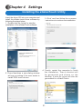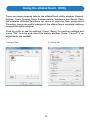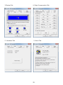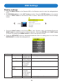
1
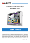
Talk to us. We listen.
42" FHD Industrial Waterproof Touch Screen Display
ADM-5842AX
USER MANUAL
Thank you for purchasing the ADM-5842AX Industrial Waterproof LCD Display. We are confident that
you will be pleased with the performance and reliability of your new display. The display is designed to
be operated in harsh environments, meet the screen performance requirements of today's demanding
industrial applications. While complying with a wide variety of industrial video formats, it delivers a
larger screen area, higher resolutions, and greater color accuracy than many displays in its price
range.
Publication date: 2014/09/02
Version No.: V2.1
Product safety precautions
Read all of these instructions and save this manual for later use. Follow all warnings and
instructions on the product.
•
Relative humidity: 25%~80%
•
Storage temperature: -20oC to 60oC(-4F to 140F)
•
Operation temperature: 0~50oC(32F to 122F)
•
Unplug the unit when not in use for an extended period of time.
•
Consult a service technician if the display does not operate normally when you have
followed the instructions in this manual.
•
Do not attempt to repair this product yourself. Always get a qualified service
technician to carry out adjustments or repairs.
•
Do not place heavy objects on the unit.
•
Use only the power cord supplied with the unit. In the event that another power cord
is used, one that is different than the one provided by the supplier, make sure that it
is certified by the local and applicable national standards.
•
If the power cable is faulty in any way, please contact the manufacturer or the nearest
authorized repair service provider for a replacement.
•
The power supply cord is used as the main disconnect device. Ensure that the socket
outlet is easily accessible after installation.
•
Overloaded AC outlets, extension cords, frayed power cords, and broken plugs are
extremely dangerous. They may, and can, result in an electrical shock or fire hazard.
Call an authorized service technician for any replacements.
•
Hands must be dry when plugging in the power cord into an AC outlet to prevent
electrical shock. Do not damage the power cord by disassembling, bending, pulling
or exposing it to heat as it may cause a fire or electrical shock.
•
Make sure to completely insert the power plug. Insecure connections can cause a
fire.
•
Unplug the display if cleaning is needed. The screen may be wiped with a dry or
slightly damp cloth when the power is off.
Important: Read all the contents of this instruction manual carefully before
you first use the ADM-5842AX Industrial Waterproof display.
2
Contents
Contents
Product safety precautions............................................................................................. . . 2
Contents............................................................................................................................ . . 3
Chapter 1 Welcome .........................................................................................................4
Introduction..................................................................................................................................... 4
Features....................................................................................................................................... . . . 5
Product specifications................................................................................................................ . . . 6
Unpacking.................................................................................................................................... . . . 8
Chapter 2 Basics.................................................................................................................9
Interfaces and remote control.......................................................................................................9
Remote control...............................................................................................................................11
Remote OSD.........................................................................................................13
Configuration.................................................................................................................................14
Physical dimensions ....................................................................................................................15
Chapter 3 Connections ....................................................................................................17
Pins in the VGA port........................................................................................................................18
Pins in the RS-232 touch port.........................................................................................................19
Pins in the Remote OSD connector................................................................................................20
Mounting the Local Host Transmitter.............................................................................................21
Mounting the display.......................................................................................................................24
Connecting the Local Host Transmitter...................................................................................26
Connecting the ADM-5842AX display.......................................................................................27
Checking connectivity for the ADM-5842AX........................................................................29
Adjusting the video quality on the display.....................................................................................30
Chapter 4 Settings...........................................................................................................31
Installing the eGalaxTouch Utility................................................................................................31
Using the eGalaxTouch Utility.....................................................................................................32
OSD Settings.................................................................................................................................34
Chapter 5 Appendix.........................................................................................................37
Maintenance and Troubleshooting..............................................................................................37
Product Limited Warranty............................................................................................................38
Frequently Asked Questions.........................................................................................................42
Disposal and Recycling Information...........................................................................................43
Disclaimer and Copyright Notice.................................................................................................43
3
Chapter 1 Welcome
Introduction
Arista Corporation's 42" industrial waterproof LCD displays are designed to
operate in harsh environments, and are ideally suited for a wide variety of
industrial environments and outdoor use.
This industrial waterproof LCD display consists of a 42", full HD display and a
smart Local Host Transmitter.
The high resolution, full HD display is capable of displaying large amounts of
critical production and process information, and provides floor personnel with
easy-to-see and easy-to-read production targets, cadence, alarms, machine
uptime and downtime measurements, and OEE (overall equipment effectiveness),
thus helping to improve productivity and efficiency in the work place. With just one cost-effective RJ-45 LAN cable, the Local Host Transmitter lets
you extend video signals that cover distances of up to 330m (1,000ft). The Local
Host Transmitter is situated near the signal source, and the ADM-5842AX full
HD display can be placed in your preferred location. With built-in EQ and GAIN
control, the transmission path can be adjusted to adapt to the cable quality
and video bandwidth to attain desired video quality. Due to loss from long
distance transmissions, the VGA RGB delay control (de-skew) function provides
compensation for R, G, B color channel signals over a normal LAN cable.In order
to give the user more control, the Local Host Transmitter also has a built-in RS232 half-duplex long range extender along with the VGA video signals.
4
Features
For the display
•
•
•
•
•
•
•
•
•
•
•
•
•
•
42” industrial waterproof display, full HD 1920 x 1080 resolution
16:9(wide) aspect ratio.
LCD protected by tempered glass.
High quality, waterproof stainless steel bezel
Computer video signals of VGA, SVGA, XGA, SXGA, WXGA, UXGA, WUXGA standard.
Supports vertical refresh rate of up to 75Hz for VGA, SVGA and XGA of VESA standard
specification. True XGA with expansion support from DOS, VGA, SVGA.
Analog RGB signal direct input offers multiscan function.
Color supports up to 8 bits per color, total 16 million colors.
Strengthened protective glass(anti-reflective optional).
Sunlight readable option
High brightness, contrast and wide viewing angles
Single control operation and transparent On-Screen-Display (OSD) user interface. Full
control of all relevant display and interface parameters via OSD.
Meets IP-67 requirements.
For the Local Host Transmitter
•
•
•
•
•
•
•
•
•
•
•
•
•
•
•
Transmission distances of up to 330m/1000 feet
Provides a VGA interface on the transmitter for local use
Supports local and remote VGA monitors.
Can extend signals using a simple RJ-45 LAN cable.
No software is required, easy installation, and supports plug-and-play.
Perfect image quality, strong anti-interference performance, image clarity and
brightness are adjustable
Supports RS-232 half-duplex
Adjustable equalization on remote display
Adjustable gain control on remote display
De-skew compensation available for RGB delay control
Wall mountable case for better stability
Supports a PC, SUN, MAC or ELINX switch with VGA video
Multi-platform support: Windows 2000/XP/Vista/Server 2000/2003/2008, Solaris, Linux,
FreeBSD, and MAC OS 9/10
Built-in lightning & surge protection
Super interference rejection
5
Product specifications
Display
6
Specifications Local Host transmitter
Technical Information
Video bandwidth
350MHz
Transmission
WUXGA [1920x1080] — 330m (1,000ft) [CAT5e]
Audio support
No
RS-232 signal type
Half-duplex & baud rate
Input video signal
1.2 Volts [peak-to-peak]
Equalization
Continuous analog control
RGB delay control
Yes
Loop-out
1 VGA loop-out at TX
ESD protection
[1] Human body model — ±15kV [air-gap discharge] & ±8kV [contact
discharge]
[2] Core chipset — ±8kV
PCB stack-up
Input
4-layer board [impedance control — differential 100Ω; single 50Ω]
1x VGA, 1x RS-232
Output
VGA connector
1x RJ-45, 1x VGA
HD-15 [15-pin D-sub female]
RJ-45 connector
WE/SS 8P8C with 2 LED indicators
RS-232 connector
Physical Informaiton
Mounting
Net Weight
Physical Dimension
Mechanical Informaiton
Mounting
Power supply
Power consumption
Operation temperature
Storage temperature
Relative humidity
DE-9 [9-pin D-sub female]
Wall mounting, Din-Rail mounting
0.530kg
6.19 X 4.04 X 1.35 inch/ 157 X 103 x 34 mm (L X W X H)
Wall mounting or DIN-RAIL mounting
5V/2A DC(Max.)
5 Watts [max]
0~50OC [32~122F]
-20~60OC [-4~140F]
20~90% RH [no condensation]
7
Unpacking
Open the package and inspect the items carefully to make sure no item is damaged and all
items listed are present in your package.
ADM-5842AX Display x1
Remote control x1
AC/DC power supply x1
t ures
Local Host Transmitter x1
6 feet VGA cable x1
6 feet AC power cord x1
Driver CD Rom x1
8
Remote OSD x1
6 feet RS-232 cable x1
RJ-45 LAN Cable x1
Chapter 2 Basics
Interfaces and remote control
Display
Front View
Rear View
1 Display screen
2 Power indicator- green for working mode, red for
standby mode.
3 Remote control IR receiver
4 DC 24V input
5 TX RJ-45 LAN port - for touch screen and video-in
6 EQ knob-Rotary control for equalization of R, G, B
8 De-skew compensation control knob:
0,2,4((0-Blue, 2-Green, 4-Red): De-skew compensation
for delay of respective RGB color channel
1, 3, 5(1-Blue, 3-Green, 5-Red): De-skew compensation
for equalization of respective RGB color channel
7: De-skew compensation for Gain.
color channel
9 Decrease or increase the level of de-skew
compensation or RGB delay control
7 GAIN knob- Rotary control for gain
10 Remote OSD connector
9
Local Host Transmitter
Front View
2
1
Rear View
3
No.
Connection
1
RS-232 IN
2
VGA IN
3
DC IN
4
VGA OUT
5
LOCAL OUT
5
4
Description
RS-232 signal source input(for touch screen use)
VGA signal source input
5V/2A DC input
Local host VGA signal output(connect to display
monitor-optional)
Transmitting signal flow(connect to ADM-5842AX
display via RJ-45 LAN cable)
10
Remote Control
6
1
7
2
3
4
5
Buttons
Description
1
POWER
• Power on or power off.
2
MENU
• Press MENU to bring up the settings menu such as:
Brightness,Contrast, etc.
3
UP
• Move the cursor or increase the data value of settings.
4
▼DOWN
• Move the cursor or decrease the data value of settings.
5
INFO
• Press to display channel information, resolution, color
space, etc.
6
Reset
• Reset settings to factory defaults.
7
Mute
• Press to eliminate or restore playback sound.
11
Using the Remote Control Correctly
Point the remote control unit no more than 5
meters from the sensor and within 60° of the
front of the display.
Remote
Sensor
30°
30°
5M Maximum
distance
Battery Installation for the Remote Control
Push 1 and pull 2 to open the
battery compartment. Insert the
battery and match the (+) and (-) on
the battery to the indicated marks.
CR2025
2
+
1
Note:
• The battery in the Remote Control normally lasts for about one year, although this depends
on how often and for what operations the Remote Control is used for.
• Use a 3V lithium battery (No. CR2025 or equivalent).
• Be careful when you press the slot of the battery compartment. Apply pressure gently with
your fingernails to avoid damages.
• Please take caution in using small button batteries and cell batteries as they are potential
choking hazards for young children. Keep stray and loose batteries away from children.
• Seek medical advice if you believe a cell or button battery has been swallowed.
• The battery must be disposed of properly according to local laws and regulations.
12
Remote OSD
The remote OSD(on screen display) that came with the unit is used for
operating the on screen controls on the display. Users can also affix it onto
a wall or board for ease of use and convenience.
Connecting the Remote OSD
• Follow the steps below to connect the Remote OSD:
• Step1: As shown in the figure below, the Remote OSD can be affixed to a wall, board
or bracket with the use of screws.
• Step2: Use the Remote OSD cable to connect to the connector located at the rear of
the ADM-5842AX display.
Rear panel
Remote OSD
(supplied)
AUTO
Buttons
AUTO
LEFT/Right
LEFT
MENU RIGHT INPUT POWER
Description
Press this button to automatically adjust the display aspect ratio.
Press for selecting, navigating or adjusting values in the menu/option
screen.
MENU
Press to display the options/menu screen
INPUT
Press to confirm selection.
POWER
Power On/Off control.
13
Configuration
There is a label located on the back of the unit that shows the unit’s serial number and
configuration. The serial number is unique to the unit, and the configuration indicates the
options the unit was built with.
The configuration is given in two parts: the model number and the order information. Model number
The model number can be parsed as followed:
For more detailed technical information, including configuration layout, please contact
Arista customer support at (510) 226-1800, ext. 400
ADM-58 4 2
LCD Size
A X
Mounting Scheme
Environmental Protection
Order information
The ordering information for each configuration is defined below.
LCD Display
Touch Screen
Bezel
Power Supply
ADM-5842AX-004
42" Wide Screen
IR
Stainless steel
24VDC Input
ADM-5842AX004-VHB
LCD Display 42" VHB Wide
Screen
Touch Screen IR
Bezel
Stainless steel
Power Supply 24VDC Input
ADM-5842AX-005
42" Wide Screen
IR
Stainless steel
110/220VAC Input
ADM-5842AX-Z04
42" Wide Screen
No Touch
Stainless steel
24VDC Input
ADM-5842AX-Z05
42" Wide Screen
No Touch
Stainless steel
110/220VAC Input
ADM-5842AX005-VHB
42" VHB Wide
Screen
IR
Stainless steel
110/220VAC Input
ADM-5842AXZ04-VHB
42" VHB Wide
Screen
No Touch
Stainless steel
24VDC Input
ADM-5842AXZ05-VHB
42" VHB Wide
Screen
No Touch
Stainless steel
110/220VAC Input
14
Physical dimension
The diagrams below show the physical and specific dimensions of the ADM-5842AX
display and Local Host Transmitter.
ADM-5842AX Display
1089mm
Front view
682mm
1067mm
1089mm
Rear view
150mm
682mm
400mm
400mm
ADM - 5842AX
Display
L(Overall
W(Overall width)
Length)
42.85”/1089mm
26.85”/682mm
15
Height
Weight
3.35”/85mm
81.6 kg
Local Host Transmitter
34mm
1.35 "
130mm
5.12 "
144mm
5.65 "
103mm
4.04 "
70mm
2.76 "
157mm
6.19 "
ADM - 5842AX Local
Host Transmitter
L(Overall
Length)
6.19”/157mm
W(Overall width)
Height
Weight
4.04”/103 mm
1.35”/34mm
0.530kg
16
Chapter 3 Connections
This section describes the connections/connectors available on the ADM-5842AX industrial
LCD display and the Local Host Transmitter.
Warning! Make sure your display is grounded at all times. Also make sure
that it is on the same ground as any other equipment connected to its
communications ports.
Connectors
Connectors are located at the bottom of the ADM-5842AX display
Connectors
Connectors
Connectors are located at the front and rear of the Local Host
17
Pins in the VGA port
5 4 3 2 1
10 9 8 7 6
15 14 13 12 11
VGA signal input connector
Pin NO. Pin Assignment
1
VGA R
2
VGA G
3
VGA B
4
NC
5
GND
6
GND
7
GND
8
GND
9
NC
10
GND
11
NC
12
TXD
13
VGA HS
14
VGA VS
15
RXD
Pin Description
Remark
VGA Red signal
VGA Green signal
VGA Blue signal
No connection
Ground
Ground
Ground
Ground
No connection
Ground
No connection
ISP program upgrade TXD signal serial transmit data
VGA H-Sync signal
VGA V-Sync signal
ISP program upgrade RXD signal Serial receive data
18
Pins in the RS-232 touch port
5 4 3 2 1
9 8 7 6
RS-232 signal input connector
Pin NO. Pin Assignment Pin Description
Remark
1
NC
No connection
2
TX
ISP program upgrade TXD signal serial transmit data
3
RX
ISP program upgrade RXD signal Serial receive data
4
NC
No connection
5
GND
Ground
6
NC
No connection
7
NC
No connection
8
NC
No connection
9
NC
No connection
19
Pins in the Remote OSD connector
5 4 3 2 1
9 8 7 6
Remote OSD connector
Pin NO. Pin Assignment
1
NC
2
INPUT
3
RIGHT
4
MENU
5
POWER
6
LEFT
7
AUTO
8
NC
9
NC
Pin Description
No connection
Input confirmation
OSD cursor control (right)/setting value adjustment
Option menu display control
Power on/off control
OSD Cursor control (left)/setting value adjustment
Display aspect ratio adjustment
No connection
No connection
20
Remark
Mounting the Local Host Transmitter
1. Wall mounting
There are two methods to mount the Local Host Transmitter: Wall mounting and DIN-rail
mounting.
The Local Host Transmitter can be placed on a shelf, table, or mounted onto a control
panel. To mount it onto a control panel, you will require the mounting screws found in the
accessory box.
Please follow the steps shown in the diagram below:
• Situate the Local Host Transmitter on a board or a wall. Firmly secure it by screwing it
in with the four “#8-32UNC” sized screws.
•
Make sure that the Local Host Transmitter is correctly and securely seated onto the
board or wall.
Wall or board
Local Host
Transmitter
Screws
It is very important that the unit is in a suitable environment. Make sure the
area is well ventilated, out of direct sunlight, away from sources of excessive
dust, dirt, heat, water, moisture and vibration.
21
2. DIN-Rail mounting
Please follow the steps as shown below to mount the Local Host Transmitter via DINRail.
• Step 1: Place the metal clasp on the back of the Local Host Transmitter, and screw it
in using “#6-32UNC screws
• Step 2: Place one Din-Rail on the wall or board, and use a screwdriver to tighten the
screws to affix the Din-Rail onto the wall or board. • Step 3: Snap the metal clasp onto the Din-rail to mount the Local Host Transmitter
onto the wall or board.
• Step 4: You can also slide the metal clasp around the Din-rail to move the Local Host
Transmitter to a desired position.
22
In order to correctly install the Local Host Transmitter, the specific dimensions are indicated
in the diagram below.
34mm
1.35 "
130mm
4 X .35
[9]
5.12 "
144mm
5.65 "
103mm
4.04 "
70mm
2.76 "
8 X .18
[5]
157mm
6.19 "
23
Mounting the display
1. Mounting the display using the VESA mounts and wall bracket
“VESA FDMI Standard” stands for Video Electronics Standards Association Flat Display
Mounting Interface Standard. The ADM-5842AX display needs be mounted on a VESAcompliant arm or bracket. And on the ADM-5842AX display, holes have been pre-drilled on
the rear of it.
As shown in the figure below, please follow these steps to mount the display.
• Step 1: Place two VESA mounts on the back of the ADM-5842AX display, and align
the holes on the VESA mounts with the holes on the display.
• Step 2: Use a screwdriver to tighten the eight “M8” size screws to fix the VESA mounts
on the display.
• Step 3: Place one wall bracket on the wall or board, and align the holes on the
bracket with the holes on the wall or board.
• Step 4: Use a screwdriver to tighten the screws to fix the wall bracket on the wall or
board.
• Step 5: Mount the display onto the wall or board through the VESA mount and wall
bracket.
24
2. VESA mounting
Mounting
150 x 400mm/5.92 x 15.75 inch
Warning! The ADM-5842AX display needs be mounted on a VESA-compliant
mount and wall bracket. Failure to properly and securely situate the display can
result in injury to personnel or damage to equipment.
25
Connecting the Local Host Transmitter
Follow the steps below to connect the Local Host Transmitter.
1. Connecting a computer:SConnect one end of the VGA /RS-232 cable to the VGA -IN/
RS-232 port of the Local Host Transmitter. Connect the other end of the VGA/RS-232 cable
to the VGA-Out/RS232 port of a computer.
2. Connecting the ADM-5842AX display: Connect one end of the RJ-45 LAN cable to
the RJ-45 LAN port of the Local Host Transmitter. Connect the other end of the RJ-45 LAN
cable to the TX RJ-45 LAN Port of ADM-5842AX display.
3. Connecting to a Display monitor: Connect one end of the VGA cable to the VGA port of
the Local Host transmitter. Connect the other end of the VGA cable to the display monitor.
4. Connecting the power supply: Connect one end of the AC/DC power adapter to the DC-in
connector of the Local Host transmitter. Connect the other end of the AC/DC power adapter to
an AC outlet.
AC outlet
Display monitor(optional)
ADM-5842AX Display
rear panel
RJ-45 LAN cable
(supplied)
ARISTA BOXPC-138G
(Sold separately)
Power supply
(supplied)
Local Host
Transmitter
VGA cable (supplied)
RS-232 cable (supplied)
26
Connecting the ADM-5842AX display
Follow the steps below to connect the ADM-5842AX display.
1. Connecting the Remote OSD:SAs shown below, the Remote OSD can be affixed to a
wall, board or bracket with the use of screws. Use the Remote OSD cable to connect to the
connector located on the rear of the ADM-5842AX.
2. Connecting the Local Host Transmitter: Connect one end of the RJ-45 LAN cable
to the TX port of the ADM-5842AX LCD display. Connect the other end of the RJ-45 LAN
cable to the RJ-45 LAN port of a computer.
3. Connecting the power supply: Connect one end of the AC/DC power supply to the DCin(24V) connector of the ADM-5842AX display. Connect the other end of AC/DC power supply
to an AC outlet.Connect Power and Cable: Connect one end of the AC/DC power supply to the
AC outlet
Power supply
(supplied)
ADM-5842AX Display
rear panel
Remote OSD(supplied)
Power cable
(supplied)
RJ-45 LAN cable
(supplied)
Local Host
Transmitter
27
The AC to DC 24V power supply provided with the ADM-5842AX does not have
environmental protection. In order to meet a degree of protection, the power supply needs
to be installed in a specific IP rating enclosure. Step1
Step2
Step3
Industrial
Enclosure
screws
In order to correctly install the power supply, the specific dimensions for the power
supply are indicated in the diagram below.
Notes:
If, for any reason, the display goes blank and gives an “Out of Range” or “No Input
Signal”, your system source is outputting a signal that goes beyond or is incompatible
with the LCD’s video A/D board. If this happens, make sure the correct signals are
inputted. If the display doesn’t work properly, it may be because:
• The resolution is too high or too low for the LCD.
• The power supply is incorrect or insufficient.
28
Checking connectivity for the ADM-5842AX
Turning on the ADM-5842AX
• Make sure the Local Host Transmitter connections(see page 26) are done correctly,
• Make sure the connections for the ADM-5842AX display(see page 27) are done
correctly.
• Then, do the following to turn the unit on:
devices.
1. Turn on your computer or other video
2. Press the Power button on the Remote Control or Remote OSD to turn
the ADM-5842AX on. Turning off the ADM-5842AX
• Press the Power button on the Remote Control or Remote OSD to turn off the ADM-5842AX
display.
• If the display is not going to be in use for an extended period of time, press the Power
button to turn off the display and disconnect the power cord from the AC outlet.
Warning! Make sure your display is grounded at all times. Also make sure that it
is on the same ground as any other equipment connected to its communications
ports.
29
Adjusting the video quality on the display
After the ADM-5842AX display has been turned on for the first time, If a blurred
display screen is seen, try to adjust the EQ and Gain rotary knobs to improve
the cable skew. GAIN rotary knobs are designed for gain control, and EQ rotary
knobs are designed for equalizing the wave form of the receiving video signal.
It is suggested to begin with adjusting the EQ rotary knob to get the input video
displayed first, and then the GAIN rotary knob to fine tune the image/video quality.
De-skew offers the flexible functionality of allowing skew compensation when VGA
(R,G,B) signals weaken due to long range transmissions or through low quality
RJ45 LAN cables. Use the (0-7) rotary knob to choose the specific (R,G,B) color
channel then use the (+ or -) rotary knob to adjust the skew.There are a total
of 31 steps and in each step there is a 2(ns) difference for adjusting the delay
between each individual color channel. With this, video quality can be further
assured.
30
Chapter 4 Settings
Installing the eGalaxTouch Utility
Insert the driver CD into your computer and
install the eGalax touch driver software by
following the steps below.
1. Double click the “setup” to start the
installation of the eGalaxTouch software.
2. Press Next,then a new dialog window
will pop up asking if the user wants to
install PS/2 touch drivers.
3. Click “next”and follow the on-screen
instructions to continue the installation.
4. Finally, restart the computer to finish
the installation. Then a shortcut will
be generated and shown on the
desktop. A new file group will also be
generated for eGalaxTouch.
31
Using the eGalaxTouch Utility
There are seven property tabs in the eGalaxTouch utility window: General,
Setting, Tools, Display, Edge Compensation, Hardware and About. Each
tab contains different functions for users to adjust to their preferences
Therefore, users can easily manage all the eGalaxTouch controller settings
through this utility window.
Click on a tab to see its settings. Press "Apply" to confirm settings and
press "OK" to save and close the dialog window. Press "Cancel" if no
adjustments are needed.
1.General Tab
2. Setting Tab
32
3.Display Tab
5. Hardware Tab
4. Edge Compensation Tab
6. About Tab
33
OSD Settings
Display settings
1. Press the MENU button on the Remote OSD or the Remote control to enter the settings/options
menu.
2.the UP/DOWN buttons or the LEFT button to select. Press the ENTER button on the remote
control or INPUT button on the Remote OSD to confirm. Select and enter the Picture Settings
screen.
Picture Mode User
Color Temperature
Aspect Ratio
Noise Reduction Middle
PC Setup
Backlight
3. Press the RIGHT button to set Picture Mode :User, Dynamic, Mild, and Standard(Press the
RIGHT button to select through the available options.), then press ENTER and/or INPUT button
to confirm the setting.Press MENU button to return to the previous screen.
4. Press the LEFT/RIGHT buttons to decrease/increase the value of a setting from 0 to 100. Press
ENTER/INPUT to confirm the setting and exit.
Tint 50
Main Menu
Picture
Sub-menu
Picture mode
Options
User, Dynamic,
Standard, Mild
Color Temperature User, Cool,
Medium, Warm
Aspect Ratio
Auto, 4:3, 16:9,
Zoom1, Zoom
2, Just Scan,
Panorama
Noise Reduction
Middle
PC Setup
Auto Adjust,
Horizontal
Pos.50, Vertical
Pos. 50, Size
50, Phase 4
Backlight
Description
Select display mode.
Select color temperature mode.
Select the aspect ratio of the viewing screen.
Set PC screen adjustments.
Select backlight on or off.
34
System settings
1. Press the MENU button to enter the settings/options screen,then press the Right
button to bring up the system setting screen.
OSD Language English
Restore Factory Default
Blending
OsdDuration 15 Sec
Light Sensor Off
Temperature Sensor Off
2.Press the UP/DOWN buttons on the remote control or the LEFT button on the Remote
OSD to select a setting. Press ENTER and/or INPUT to enter/confirm a setting. Press
the MENU button to return to the previous screen.
3. To exit the settings screen, press the Exit button on the remote control.
Option
OSD Language
Restore Factory
Default
Blending
Osd Duration
Light Sensor
Temperature
Sensor
English
......
Off, Low,
Middle, High
Select the OSD display language.
CAUTION: Choosing this function will reset all
your settings to the factory defaults.
Select the blending mode.
Off, 5 Sec, 10 Select OSD duration time.
Sec, 15 Sec
Off, On
Select to turn light sensor on or off.
Off, On
Select to turn temperature sensor on or off.
35
Input source settings
1. Press the MENU button to enter the settings/options screen, then continuously press
the Right button to bring up the Input Source setting screen.
2. Press the UP/DOWN buttons or the LEFT button to select (DVI, PC-RGB) item, then
press the ENTER or INPUT buttons to confirm the selection and exit.
Input Source
DVI, PC-RGB,
Select the input source signal.
36
Chapter 5 Appendix
Maintenance and troubleshooting
1. Maintenance
Regular maintenance of the ADM-5842AX industrial waterproof display can help prevent
damage or downtime.
Warning! Do not operate or service the unit with its chassis open. There are
hazardous voltages inside. Service should only be performed by qualified and
authorized personnel. Make sure your industrial display is powered down and
unplugged before removing the cover or working on internal components.
Replacing the Backlights
LCD backlights are rated at the number of hours of operation until they are at half of their
original brightness. The ADM-5842AX industrial waterproof display backlights are rated at
50,000 hours — that equates to six years of continuous service.
Signs that the backlights may need replacing include:
1) The top and/or the bottom of the screen is dim.
2) The image on the screen flickers.
3) The video appears to be blank in normal light, but can be very faintly seen in strong external light.
Note: The backlights are not user serviceable. If the backlights need to be replaced, you
must return the unit to Arista for service.
2. Troubleshooting
Before calling for service, you can check the following table on symptoms and solutions.
Symptom
Possible Causes
No LCD display - No power
image
- No video signal
Half of the
image is dark
- Problem with the
backlights
Actions
- Verify that the Power On LED is lit.
- Check to see that the video source is on and
operating, Perhaps the source is outputting to
a different display.
- Contact Arista customer support.
LCD image is - Adjustments
- Reset to factory defaults.
too bright or too - Unrecognizable sync - Verify the supplied video format (XGA or
white
patterns
SXGA).
LCD image is
not centered
- Adjustments
- Unrecognized video
format
- Adjustments
Configuration
changes not
accepted by the
display
Display jitters or - Adjustments
flickers
- Adjust the positioning.
- Verify the supplied video format (XGA or
SXGA).
- When making adjustments, be sure to “back
out” of the adjustment menus up to the main
menu level.
- Adjust Phase and Frequency for best image.
37
3. Product Limited Warranty
Arista Corporation ADM series LCD display purchased in the U.S. and Canada come with a
3-year limited warranty. The following sections describe the limited warranties and return policies
for the North America region.
1) Limited Warranty Coverage
• If a product does not work properly because of a defect in materials or workmanship, Arista
Corporation will, for the length of a period of three years, starting with the date of the original
purchase (invoice date), at its discretion either repair your product with new or refurbished
parts, or replace it with new or a refurbished product.
• The decision to repair or replace will be made by Arista Corporation During the “Labor”
Limited Warranty period, there will be no charge for labor. During the “Parts” Limited Warranty
period, there will be no charge for parts.
• The customer pays the freight for shipping the defective products to Arista Corp. After repairs
or replacement, Arista Corporation will ship and pay UPS Ground for the products being
shipped back to the customer.
• This Limited Warranty only applies to products purchased and serviced in the North America
region. Customers outside of the United States will need to pay the freight for shipping to
Arista Corp. and shipping back to the customer after repairs or replacement.
2) Limited Warranty Limits and Exclusions
• This Limited Warranty only covers failures due to defects in material or workmanship, and
does not cover normal wear and tear, or cosmetic damages .
• The Limited Warranty does not cover damages due to external causes including, but not
limited to, failures which are caused by products not supplied by Arista Corporation.
• The Limited Warranty does not cover damages and/or failures which result from negligence,
accidents, misuse, abuse, mishandling, misapplication, alteration, faulty installation, set-up
adjustment, improper maintenance, power surge, problems with electrical stability, failure
to maintain environmental conditions within operating range specified by the manufacturer,
relocations or attempts to relocate systems, lightning damage, modification, service by
anyone other than authorized service providers, usage not in accordance with product
instructions, failure to perform required preventative maintenance, problems caused by
use of parts and components not supplied by Arista, and/or adding or altering components
without concurrence from Arista Technical Support.
• Any signs showing that the serial numbers have been altered or tampered with will void this
warranty.
• There is no expressed warranty except as stated under “Limited Warranty Coverage”. Under
no equitable theory shall Arista Corporation be held liable for monetary and/or non-monetary
damages resulting from the normal or abnormal usage of our products. Use, distribution and/
or similar engagement of our products constitute implied agreement to these and similar
Arista Corporation Limited Liability policies.
4.Technical Support
1) Technical Support Availability
• Arista Corporation is dedicated to your satisfaction. Arista’s Technical Support Team will
make every effort to solve the problem over the phone or through e-mail. If we cannot solve
the problem over the phone or through e-mail, an RMA number will be issued.
• Information Needed When You Call: Product Serial Number & Details of the Problem.
2) Technical Support Contact Information
• Technical Support Hours: Monday through Friday: 8:30am-5:30pm PST
• Technical Support Phone Number : Phone: (510) 226-1800 ext. 400, Fax: (510) 226-1890
• Technical Support E-mail:[email protected]
38
5. RMA Procedures
Return Material Authorizations
• All returns require an RMA (Returned Material Authorization) number. Please contact Arista’s
customer service representative or complete the RMA request form to obtain an RMA number
prior to returning product.
• Returns will be authorized in accordance with the following policy: If it is deemed that the unit/
part should be returned, Arista’s customer service representative will give the customer a
return authorization number and ship to address to return the product.
• Products will not be accepted by Arista Corp. RMA department for return if not accompanied
by a valid RMA number, which must be clearly marked on the outside of the package.
• Products must be returned within 30 days after the date of when the RMA number was issued.
After the 30-day period, the RMA number issued will be invalid. Please do not return products
with invalid RMA numbers; Contact Arista’s customer service representative if your RMA
number is invalid.
Warranty Returns
• Products to be returned must be within the applicable warranty period. If the warranty period
is over, the original product will be returned to the customer.
• The RMA number for Warranty Return will be issued within 24 hours from the time that the
RMA application form is received by Arista.
Non-Warranty Returns
• If the customer wishes to return a product for repair that is no longer within the warranty
period, or for damage not covered by the warranty, an Arista sales representative will inform
the customer of the estimated cost of the repair.
• Return of the product will count as the authorization to repair and agreement to pay for the
cost of repair, whether or not it exceeds the original estimate.
6. RMA Credit Policy
Returns for Credit & Credit Types
Returns for credit that require Arista’s management approval may take up to 48 hours for
processing/approval. Products can be returned for credit with the following conditions:
Dead on Arrival (DOA): Customer must report DOA units to Arista’s RMA department in 14
calendar days after the product is received. Customer can request either return for credit or
replacement. If replacement is requested, Arista will ship the replacement in 7 calendar days and
invoice the customer for the replacement. A credit memo will be issued to the customer after the
DOA product is received and verified.
Evaluation Return: Customer must notify Arista’s RMA department before or at the end of the
evaluation period if the customer decides to return the evaluation unit. An RMA number must be
obtained from Arista prior to returning the unit.
Short Shipment: The customer must report for any item received short-shipped or wrong
products received in 7 calendar days after the product is received. The customer can request
either: shipment of missing items, replacement of wrong items or return for credit. If shipment
of missing items or replacement of wrong items is requested, Arista will ship the replacement
in 7 calendar days. A credit memo will be issued to the customer after the returned product is
received and verified.
Non-Open-Box Return: In the event, where a customer places an incorrect order, over stock or
double orders. The customer can request return for credit with the following restocking fee applied.
Restocking Fee: A 15% restocking fee would apply to the non-open-box when returned within 3
months after invoice date. A 30% restocking fee would apply to the non-open-box returned within
6 months. Beyond 6 months after invoice date, a 50% restocking fee would apply to the nonopen-box returned within 12 months. Beyond 12 months after invoice date, Arista will not grant
authorization to return the non-open-box for credit.
Return Condition: All valid returns for credit products must be returned in the original packaging
in “as new" condition with all items and accessories originally shipped with the product. Any
damages will be assessed and the cost of repair or refurbishment will be deducted from the
credit issued.
No Credit DOA: No credit will be given to the customer for DOA products received by Arista
beyond 30 calendar days after the invoice date. No credit will be given to all non-cancellable,
non-returnable, custom order parts.
39
7. RMA Transportation Policy
Transportation Charges
• All customers are responsible for all freight charges involved in shipping the defective
products back to Arista Corporation will cover the cost of returning products that are under
warranty via UPS Ground to customers in the United States after repairs or replacement.
• International customers are responsible for all transportation, insurance, duties and other
similar charges for all returned products shipped outside of the United States must ensure
that the product is appropriately packaged. Shipping damages resulting from improper
packaging will be the customer’s responsibility.
• Arista is not responsible for products lost during shipment. All products being returned for
Limited Warranty repair or replacement must be sent freight prepaid.
Transportation Damages
• In cases of transportation damage, the customer is responsible for filing any and all claims
with the shipping carrier.
• To avoid any potential risk that an RMA product is lost or damaged while in transit to Arista,
it is recommended that the customer insures and declares the full value of the RMA product.
The customer is 100% responsible for the RMA product while in transit to Arista.
• We urge customers to pack the RMA product carefully to avoid transit damage.
Refused Shipment Restocking Fees
• If a customer refuses a shipment, credit will be issued after the refused product is received
and verified by Arista. The shipping charge plus 15% restocking fees will be billed to the
customer.
8. RMA Shipping Instruction
Product Non-Acceptance
• Products will not be accepted by Arista Corporation if not accompanied by a valid RMA
number, which must be clearly marked on the outside of the package.
• Any products refused by Arista will incur the fees and/or charges applied by the shipping
carrier, and shall be the sole liability of the original shipper.
Sample RMA Shipping Label
ARISTA CORPORATION
Attention: RMA Department
40675 Encyclopedia Circle
Fremont, CA 94538
RMA: # _______________
Package Identification
• Each box must reference the following information: Customer/Contact Name · Return
Address · Phone Number · RMA Number (issued by an authorized ARISTA source).
• The RMA number must be written on the outside of the shipping container for identification
purposes.
• Shipments not properly identified will be refused. • To avoid any discrepancy of items received, please do not return accessories (manuals,
driver CDs, OS CDs, cables, etc.) with the RMA unit in need of repair.
• If available, use the original box/packaging to ship back RMA unit to avoid transit damage.
40
RMA Rejection Policy
Products will not be accepted by Arista Corporation if not accompanied by a valid RMA number,
which must be clearly marked on the outside of the package. Arista reserves the rights to return
any RMA product received that does not comply with the information given on the original Return
Material Authorization (RMA) request, such as:
• Invalid RMA number
• RMA number not visible and/or not on the box shipping label
• RMA condition described by the customer differs from the actual condition of the product
• Expired RMA number
• Unauthorized return (no RMA # was issued)
• No Arista serial number on the product
• Product is physically damaged
If you have any questions regarding Arista’s RMA procedures, product returns policies and/or
other similar issues, please call Arista’s Customer Service and RMA Department during office
hours, Monday through Friday (8:30am-5:30pm PST)
• Phone: (510) 226-1800 ext. 400
• Fax: (510) 226-1890
• Email: [email protected]
9. Arista’s Limited Liability
• Arista Corporation is not liable for incidental or consequential damages resulting from the use
of Arista products or arising out of any breach of Arista's full limited warranty.
• Under no equitable theory shall Arista Corporation be held liable for monetary and/or nonmonetary damages resulting from the normal or abnormal usage of our products. Use,
distribution and/or similar engagement of our products constitute implied agreement to these
and similar Arista Corporation Limited Liability policies.
• Arista Corporation is not liable for damages or reimbursement for lost time, lost revenue, cost
of having someone remove or re-install an installed unit if applicable, or travel to and from
the service providers.
• All expressed and implied warranties, including the limited warranty of Merchantability are
limited to the period of the limited warranty, unless, otherwise, indicated in writing by Arista
Corporation.
Customer Responsibilities
• By requesting service, the eligible customer acknowledges the terms of the limited warranty,
including the disclaimer and limitation of liability provision.
• Prior to seeking service, customers must back-up all data, programs, files and/or similar
digital documents that may become damaged and/or lost due to service.
• Arista Corporation, WITHOUT LIMITATION, is not responsible for lost, damaged or otherwise
destroyed data due to service.
10. Disclaimer
ARISTA RESERVES THE RIGHT TO CHANGE ANY OF ITS TERMS OF SERVICE,
WARRANTY POLICIES, SERVICE PROGRAMS, SERVICE METHODS AND/OR SIMILAR
POLICIES AT ANY TIME AND WITHOUT PRIOR OR FORMAL NOTICE TO ITS CUSTOMERS,
VENDORS, RESELLERS, END USERS OR SIMILAR.
41
Frequently asked questions
What does ‘refresh rate’ mean in relation to an LCD display?
The refresh rate is of much less relevance for LCD displays. LCD displays stay at a stable, flicker-free
image at 60Hz. There is no visible difference between 85Hz and 60Hz.
Are LCD display Plug-and-Play?
Yes, the displays are Plug-and-Play compatible with Windows XP, 7 and 8
What is a Liquid Crystal Display?
A Liquid Crystal Display (LCD) is an optical device that is commonly used to display ASCII characters
and images on digital items such as watches, calculators, portable game consoles, etc. LCD is the
technology used for displays in notebooks and other small computers. Like light-emitting diode and
gas-plasma technologies, LCD allows displays to be much thinner than cathode ray tube (CRT)
technology. LCD consumes much less power than LED and gas-displays because it works on the
principle of blocking light rather than emitting it.
What is polarization ?
Polarization is basically directing light to shine in one direction.Light comes in the form of
electromagnetic waves. Electric and magnetic fields oscillate in a direction perpendicular to the
propagation of the light beam. The direction of these fields is called the 'polarization direction'. Normal
or non-polarized light has fields in several directions; polarized light has a field in only one direction.
What kind of wide-angle technology is available? How does it work?
The TFT LCD panel is an element that controls/displays the inlet of a backlight using the dualrefraction of a liquid crystal. Using the property that the projection of inlet light refracts toward the major
axis of the liquid element, it controls the direction of inlet light and displays it. Since the refraction ratio
of inlet light on liquid crystal varies with the inlet angle of the light, the viewing angle of a TFT is much
narrower than that of a CDT. Usually, the viewing angle refers to the point where the contrast ratio
is 10. Many ways to widen the viewing angle are currently being developed and the most common
approach is to use a wide viewing angle film, which widens the viewing angle by varying the refraction
ratio. IPS (In Plane Switching) or MVA (Multi Vertical Aligned) is also used to give a wider viewing
angle.
42
Disposal and Recycling Information
Your display and Local Host Transmitter must be disposed of properly according to
local laws and regulations.
Because your remote control contains a battery, it must be disposed of separately
from household waste.
When your display and Local Host Transmitter reach the end of their life cycle,
contact your local authorities to know about recycling options.
This symbol on the product or in the manual means that your electrical
or electric equipment should be disposed at the end of its life
cycle separately from your household waste. There are separate collection
systems for recycling in the EU. For more information, please contact the local
authority or your retailer where you purchased the product.
Disclaimer and Copyright Notice
Disclaimer
All the information, design and specifications contained in this manual were
correct in this publication. However, as the product goes under continuous upgrades,
the final device may have slight differences. The contents of this manual
is subject to changes without prior notice, and we shall not be liable for any
errors contained herein or for incide or consequential damages in
connection with the furnishing, performance, or use of this manual.
contained in this manual were correct in this
© Copyright 2014
The information contained in this user’s manual and all accompanying documentation
is copyrighted and all rights are reserved. This publication may not, in whole or in part,
be reproduced, transcribed, stored in a retrieval system, translated into any language or
computer language, or transmitted in any form whatsoever without the prior written consent
from the manufacturer, except for copies retained by the purchasers for their personal
archival purposes. The manufacturer reserves the right to revise this user’s manual and
all accompanying documentation and to make changes in the content without obligation to
notify any person or organization of the revision or change.
IN NO EVENT WILL THE VENDOR BE LIABLE FOR DIRECT, INDIRECT, SPECIAL,
INCIDENTAL, OR CONSEQUENTIAL DAMAGES ARISING OUT OF THE USE OR
INABILITY TO USE THIS PRODUCT OR DOCUMENTATION; EVEN IF ADVISED OF
THE POSSIBILITY OF SUCH DAMAGES. IN PARTICULAR, THE VENDOR SHALL NOT
HAVE LIABILITY FOR ANY HARDWARE, SOFTWARE, OR DATA STORED OR USED
WITH THE PRODUCT, INCLUDING THE COSTS OF REPAIRING, REPLACING,OR
RECOVERING SUCH HARDWARE, SOFTWARE, OR DATA.
All trademarks mentioned in this document are acknowledged. The specifications in this
manual are subject to change without notice.
43
Talk to us. We listen.
TM
Arista Corporation
40675 Encyclopedia Circle, Fremont, CA 94538 U.S.A.
Tel: (510) 226-1800 Fax: (510) 226-1890
http://www.goarista.com