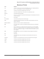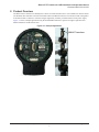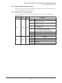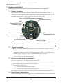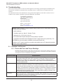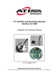
1
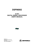
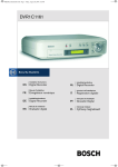
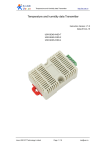
EtherCAT F/T Interface for OEM
Installation and Operation Manual
Document #: 9610-05-1032
August 2014
Engineered Products for Robotic Productivity
Pinnacle Park • 1031 Goodworth Drive • Apex, NC 27539 USA • Tel: 919.772.0115 • Fax: 919.772.8259 • www.ati-ia.com • Email: [email protected]
EtherCAT F/T Interface for OEM Installation and Operation Manual
Document #9610-05-1032-03
Foreword
Information contained in this document is the property of ATI Industrial Automation, Inc. and shall not be reproduced in
whole or in part without prior written approval of ATI Industrial Automation, Inc. The information herein is subject to
change without notice and should not be construed as a commitment of ATI Industrial Automation, Inc. This manual is
periodically revised to reflect and incorporate changes made to the F/T system.
ATI Industrial Automation, Inc. assumes no responsibility for any errors or omissions in this document.
Copyright © by ATI Industrial Automation, Inc., Apex, North Carolina USA. All Rights Reserved. Published in the USA.
In consideration that ATI Industrial Automation, Inc. (ATI) products are intended for use with robotic and/or automated
machines, ATI does not recommend the use of its products for applications wherein failure or malfunction of an ATI
component or system threatens life or makes injury probable. Anyone who uses or incorporates ATI components within
any potentially life-threatening system must obtain ATI’s prior consent based upon assurance to ATI that a malfunction
of ATI’s component does not pose direct or indirect threat of injury or death, and (even if such consent is given) shall
indemnify ATI from any claim, loss, liability, and related expenses arising from any injury or death resulting from use of
ATI components.
All trademarks belong to their respective owners.
Windows™ is a registered trademark of Microsoft Corporation.
Note
Please read the manual before calling customer service. Before calling, have the following
information available:
1. Serial number (e.g., FT01234)
2. Transducer model (e.g., Nano17, Gamma, Theta, etc.)
3. Calibration (e.g., US-15-50, SI-65-6, etc.)
4. Accurate and complete description of the question or problem
5. Computer and software information. Operating system, PC type, drivers, application
software, and other relevant information about your configuration.
If possible, be near the F/T system when calling.
How to Reach Us
Sale, Service and Information about ATI products:
ATI Industrial Automation
1031 Goodworth Drive
Apex, NC 27539 USA
www.ati-ia.com
Tel: 919.772.0115
Fax: 919.772.8259
E-mail: [email protected]
Technical support and questions:
Application Engineering
Tel: 919.772.0115, Option 2, Option 2
Fax: 919.772.8259
E-mail: [email protected]
Pinnacle Park • 1031 Goodworth Drive • Apex, NC 27539 USA • Tel: 919.772.0115 • Fax: 919.772.8259 • www.ati-ia.com • Email: [email protected]
2
EtherCAT F/T Interface for OEM Installation and Operation Manual
Document #9610-05-1032-03
Table of Contents
1.Safety.......................................................................................................................................... 6
1.1
Explanation of Notifications.......................................................................................................... 6
1.2
General Safety Guidelines............................................................................................................. 6
1.3
Safety Precautions......................................................................................................................... 6
2. Product Overview...................................................................................................................... 7
3. Compatible Transducer............................................................................................................ 8
4. ECATOEM Interface Board....................................................................................................... 8
4.1Connectors................................................................................................................................... 10
4.1.1
P900 Connector for Optional 24VDC Power & Monitor Signal Interface........................... 10
4.1.2
P901 Connector for EtherCAT Interfaces.......................................................................... 11
4.1.3
P902 Connector for optional external LEDs...................................................................... 11
4.1.4
P904 Connector for Transducer Strain Gage Signals....................................................... 11
4.2Switch............................................................................................................................................ 12
4.2.1SW1................................................................................................................................... 12
4.3LEDs.............................................................................................................................................. 12
4.3.1
LED900 Link/Activity......................................................................................................... 12
4.3.2
LED901 EtherCAT Status.................................................................................................. 12
4.3.3
LED902 Board status........................................................................................................ 13
5.Operation................................................................................................................................. 14
5.1
Sample Rate.................................................................................................................................. 14
5.2Filtering......................................................................................................................................... 14
5.3
Threshold Monitoring.................................................................................................................. 14
5.4
Discrete output............................................................................................................................. 14
5.5
Tool Transformation..................................................................................................................... 14
6. EtherCAT Bus Interface.......................................................................................................... 15
6.1
PDO Interface................................................................................................................................ 15
6.2
EtherCAT Dictionary Objects (SDO Data) ................................................................................. 15
6.2.1
Object 0x2020: Tool Transformation.................................................................................. 15
6.2.2
Object 0x2040: Calibration................................................................................................ 16
6.2.3
Object 0x2060: Monitor Condition..................................................................................... 18
6.2.4
Object 0x2080: Diagnostic readings.................................................................................. 18
6.2.5
Object 0x2090: Version..................................................................................................... 19
6.2.6
Object 0x6000: Reading Data........................................................................................... 19
6.2.7
Object 0x6010: Status Code............................................................................................. 20
6.2.8
Object 0x6020: Sample Counter....................................................................................... 21
6.2.9
Object 0x7010: Control Codes.......................................................................................... 21
Pinnacle Park • 1031 Goodworth Drive • Apex, NC 27539 USA • Tel: 919.772.0115 • Fax: 919.772.8259 • www.ati-ia.com • Email: [email protected]
3
EtherCAT F/T Interface for OEM Installation and Operation Manual
Document #9610-05-1032-03
7. Hardware Installation.............................................................................................................. 22
7.1
Chassis Grounding...................................................................................................................... 22
7.2
Transducer Handling.................................................................................................................... 22
7.3
Ground and cable shield considerations................................................................................... 22
7.4
Power Supply Considerations.................................................................................................... 22
7.5Installation.................................................................................................................................... 23
8.Troubleshooting...................................................................................................................... 24
8.1
Questions and Answers.............................................................................................................. 24
8.1.1
Errors with Force and Torque Readings............................................................................ 24
9. Specifications.......................................................................................................................... 25
9.1
Storage and Operating Conditions............................................................................................. 25
9.2
Electrical Specifications.............................................................................................................. 25
9.3
Weights and Dimensions............................................................................................................. 25
10.Drawings.................................................................................................................................. 26
11. Terms and Conditions of Sale................................................................................................ 27
Pinnacle Park • 1031 Goodworth Drive • Apex, NC 27539 USA • Tel: 919.772.0115 • Fax: 919.772.8259 • www.ati-ia.com • Email: [email protected]
4
EtherCAT F/T Interface for OEM Installation and Operation Manual
Document #9610-05-1032-03
Glossary of Terms
Term
Definition
CoE
CANopen over EtherCAT, the preferred embedded protocol for configuring EtherCAT
devices. Used within SDO to encode the configuration data.
DINT
A data type representing an unsigned integer with 32 bits.
E-Exit
ATI’s E-Exit transducers have a cable with an over-molded strain relief.
EtherCAT
An industrial automation fieldbus.
FoE
File access over EtherCAT, the preferred embedded protocol for uploading new firmware
to EtherCAT devices.
F/T
Force/Torque.
F/T Transducer
Converts force and torque into an electrical signal.
MAP
The Mounting Adapter Plate (MAP) is the transducer plate that attaches to the fixed
surface or robot arm.
MOLEX PicoBlade
Product series from the connector manufacturer Molex.
PDO
Process Data Object, a protocol for reading and writing real-time process information
cyclically.
PoE
Power-over-Ethernet, is a method of delivering electrical power to a PoE-compatible
Ethernet device through the Ethernet cable. This simplifies installation of the Ethernet
device since a separate power supply is not needed. The EtherCAT OEM F/T system is
PoE compatible.
SDO
Service Data Object, a protocol for reading and writing configuration information
acyclically.
STG
Strain Gage
TAP
Tool Adapter Plate (TAP) is the transducer surface that attaches to the load to be
measured.
Transducer
Transducer is the component that converts the sensed load into electrical signals.
UDINT
A data type representing an unsigned integer with 32 bits.
UINT
A data type representing an unsigned integer with 16 bits.
USINT
A data type representing an unsigned integer with 8 bits.
Pinnacle Park • 1031 Goodworth Drive • Apex, NC 27539 USA • Tel: 919.772.0115 • Fax: 919.772.8259 • www.ati-ia.com • Email: [email protected]
5
EtherCAT F/T Interface for OEM Installation and Operation Manual
Document #9610-05-1032-03
1. Safety
The safety section describes general safety guidelines to be followed with this product, explanation of the
notification found in this manual, and safety precaution that apply to the product. More specific notification are
imbedded within the sections of the manual where they apply.
1.1 Explanation of Notifications
The notifications included here are specific to the product(s) covered by this manual. It is expected that the
user heed all notifications from the robot manufacturer and/or the manufacturers of other components used
in the installation.
DANGER: Notification of information or instructions that if not followed will result in
death or serious injury. The notification provides information about the nature of the
hazardous situation, the consequences of not avoiding the hazard, and the method for
avoiding the situation.
WARNING: Notification of information or instructions that if not followed could result
in death or serious injury. The notification provides information about the nature of the
hazardous situation, the consequences of not avoiding the hazard, and the method for
avoiding the situation.
CAUTION: Notification of information or instructions that if not followed could result
in moderate injury or will cause damage to equipment. The notification provides
information about the nature of the hazardous situation, the consequences of not
avoiding the hazard, and the method for avoiding the situation.
NOTICE: Notification of specific information or instructions about maintaining, operating,
installation, or setup of the product that if not followed could result in damage to equipment. The
notification can emphasize but is not limited to specific grease types, good operating practices,
or maintenance tips.
1.2 General Safety Guidelines
The customer should verify that the transducer selected is rated for maximum loads and moments expected
during operation. Refer to F/T Transducer Manual (9620-05-Transducer Section—Installation and
Operation Manual) found in Net F/T Installation and Operation Manual (9610-05-1022) or contact ATI
Industrial Automation for assistance. Particular attention should be paid to dynamic loads caused by robot
acceleration and deceleration. These forces can be many times the value of static forces in high acceleration
or deceleration situations.
1.3 Safety Precautions
CAUTION: Do not remove any fasteners or disassemble transducers without a
removable mounting adapter plate. These include Nano, Mini, IP-rated, and some
Omega transducers. This will cause irreparable damage to the transducer and void the
warranty. Leave all fasteners in place and do not disassemble the transducer.
CAUTION: Do not probe any openings in the transducer. This will damage the
instrumentation.
CAUTION: Do not exert excessive force on the transducer. The transducer is a
sensitive instrument and can be damaged by applying force exceeding the single-axis
overload values of the transducer and cause irreparable damage. Small Nano and Mini
transducers can easily be overloaded during installation. Refer to the F/T Transducer
manual (9620-05-Transducer Section) for specific transducer overload values.
Pinnacle Park • 1031 Goodworth Drive • Apex, NC 27539 USA • Tel: 919.772.0115 • Fax: 919.772.8259 • www.ati-ia.com • Email: [email protected]
6
EtherCAT F/T Interface for OEM Installation and Operation Manual
Document #9610-05-1032-03
2. Product Overview
The EtherCAT F/T Interface for OEM System consists of an ATI transducer and a F/T-to-EtherCAT interface board
(ECATOEM). The transducer selected will include a Molex PicoBlade connector. The interface board is designed to
be mounted within a customer’s enclosure and gets supplied by customer provided 24VDC or PoE power supply.
Figure 2.1 shows a sample application using the ECATOEM mounted in a segment of a light weight arm and a
Mini45 transducer mounted on the arm.
Figure 2.1—Sample Application
MINI45 Transducer
Pinnacle Park • 1031 Goodworth Drive • Apex, NC 27539 USA • Tel: 919.772.0115 • Fax: 919.772.8259 • www.ati-ia.com • Email: [email protected]
7
EtherCAT F/T Interface for OEM Installation and Operation Manual
Document #9610-05-1032-03
3. Compatible Transducer
Transducers with part numbers ending in EC8 are custom designed for use with ECATOEM. It differs from a
standard Nano or Mini transducers in the following features:
•
MOLEX PicoBlade connector contacts crimped to the eight wires of the transducer cable
Figure 3.1—Transducer with Strain Relieved EC8 Cable
Strain Relief
Molex Picoblade
Connector
Transducer with EC8 Cable
4. ECATOEM Interface Board
The ECATOEM provides an EtherCAT bus interface for ATI’s TW transducers. Equipped with an 8-pin MOLEX
PicoBlade connector (like the 9105-TW-MINI45-AE-0.3-EC8), they can be plugged directly into the ECATOEM
interface board.
Figure 4.1—ECATOEM System
Optional 24VDC
Power and Monitor
Signal
Optional
External
LED's
EtherCAT
Interface Board
Transducer
EtherCAT
with Optional PoE
Pinnacle Park • 1031 Goodworth Drive • Apex, NC 27539 USA • Tel: 919.772.0115 • Fax: 919.772.8259 • www.ati-ia.com • Email: [email protected]
8
EtherCAT F/T Interface for OEM Installation and Operation Manual
Document #9610-05-1032-03
The 9105-ECATOEM interfaces with the transducer’s strain gages via connector P903 and P904. The strain gage
signals get digitized with a 16bit A/D converter, multiplied with the selected calibration matrix and the resulting
force/torque data are then transmitted over an EtherCAT bus interface.
Up to 16 transducer calibrations can be stored in the on-board EEPROM.
The ECATOEM can be supplied with a DC voltage between 20V and 48V or with PoE.
Figure 4.2—ECATOEM Block Diagram
Pinnacle Park • 1031 Goodworth Drive • Apex, NC 27539 USA • Tel: 919.772.0115 • Fax: 919.772.8259 • www.ati-ia.com • Email: [email protected]
9
EtherCAT F/T Interface for OEM Installation and Operation Manual
Document #9610-05-1032-03
Figure 4.3—ECATOEM – Components
Top View
1
(B) Mounting Hole
SW1 Dip Switch
P900
Optional 24VDC Power
and Monitor Signal
1
LED901
EtherCAT Status
LED902
Board Status
1
P902
Optional External LEDs
(A) Chassis Connection
LED900
Activity
P904
Transducer Strain Gage Signals
(C) Chassis Connection
1
Bottom View
P901
EtherCAT Interface
with Optional PoE
P903
Internal Use Only
4.1 Connectors
The following connectors are available on the ECATOEM PCB Assembly:
4.1.1 P900 Connector for Optional 24VDC Power & Monitor Signal Interface
Mating connector housing: Molex 51021-0700
Mating connector contact: Molex 50058-8000
Pin No. Signal Name Description
1
SL_GND
24V Power Supply Ground
2
RS485-
- Serial Interface to NetBox
3
DRAIN
Serial Interface Shield
4
RS485+
+ Serial Interface to NetBox
5
SL_VP
24V Power Supply Positive
6
MONITOR_E Monitor signal: emitter contact of opto isolator
7
MONITOR_C Monitor signal: collector contact of opto isolator
Pinnacle Park • 1031 Goodworth Drive • Apex, NC 27539 USA • Tel: 919.772.0115 • Fax: 919.772.8259 • www.ati-ia.com • Email: [email protected]
10
EtherCAT F/T Interface for OEM Installation and Operation Manual
Document #9610-05-1032-03
4.1.2 P901 Connector for EtherCAT Interfaces
Mating connector housing: Molex 51021-0500
Mating connector contact: Molex 50058-8000
Pin No. Signal Name Description
1
TX+
Ethernet Transmit +
2
TX-
Ethernet Transmit -
3
RX+
Ethernet Receive +
4
RX-
Ethernet Receive -
5
Shield
Ethernet cable shield
4.1.3 P902 Connector for optional external LEDs
Mating connector housing: Molex 51021-0900
Mating connector contact: Molex 50058-8000
Pin No. Signal Name
Description
1
RUN_LED
2
+3.3V
3
ACTIVITY_LED
4
+3.3V
5
Connect to cathode of optional external EtherCAT RUN LED
Connect to anode of optional external LEDs
Connect to cathode of optional external ACTIVITY LED
Connect to anode of optional external LEDs
RED_STATUS_ Connect to cathode of optional external Board Status LED
LED
6
Reserved
For uC programming
7
Reserved
For uC programming
8
Reserved
For uC programming
9
DGND
Ground for +3.3V; used for uC programming
9
8
7
6
5
4
3
2
1
3.3V
Figure 4.4—P902 LED Wiring Diagram
P902 - Optional External LEDs
4.1.4 P904 Connector for Transducer Strain Gage Signals
Mating connector housing: Molex 51021-0800
Mating connector contact: Molex 50058-8000
Pin No. Signal Name Description
1
+VSG
5V, Positive strain gage bridge supply voltage
2
-VSG
0V, Negative strain gage bridge supply voltage
3
G0
Strain gage 0 voltage
4
G1
Strain gage 1 voltage
5
G2
Strain gage 2 voltage
6
G3
Strain gage 3 voltage
7
G4
Strain gage 4 voltage
8
G5
Strain gage 5 voltage
Pinnacle Park • 1031 Goodworth Drive • Apex, NC 27539 USA • Tel: 919.772.0115 • Fax: 919.772.8259 • www.ati-ia.com • Email: [email protected]
11
EtherCAT F/T Interface for OEM Installation and Operation Manual
Document #9610-05-1032-03
4.2 Switch
The following switch is available on the ECATOEM PCB Assembly:
4.2.1 SW1
The two-position DIP switch is currently unused.
Position
ON/OFF
Description
ON
Do Not Use
OFF
Default settings OFF
ON
Do Not Use
OFF
Default settings OFF
1
2
NOTICE: Leave Dip switch in Default state. Changing Dip Switch settings may
adversely affect the EtherCAT board functionality.
4.3 LEDs
The following LEDs are available on the ECATOEM PCB Assembly:
4.3.1 LED900 Link/Activity
One green LED signals activity on the EtherCAT port.
LED State
Link
Activity
Condition
Off
No
No
Port closed
Green
Yes
No
Port open
Flashing Green
Yes
Yes
Port open
4.3.2 LED901 EtherCAT Status
One dual-color LED signals the status of the EtherCAT Network in the following way.
LED State
OFF
RUN State ERROR State Description
INIT
No
Device is in state INIT
GREEN
Blinking
PRE-OP
No
Device is in state PRE-OPERATIONAL
GREEN
Single Flash
SAFE-OP
No
Device is in state SAFE-OPERATIONAL
OP
No
Device is in state OPERATIONAL
GREEN
RED Double
Flash
Process Data
Watchdog
Timeout
RED Single
Flash
Local Error
RED
Blinking
Invalid
Configuration
Error
An application watchdog timeout has
occurred. E.g. Sync Manager Watchdog
timeout
Slave device application has changed the
EtherCAT state autonomously, due to local
error. E.g. device changes its EtherCAT
state from OP to SAFE-OP due to a
synchronization error
General configuration error.
E.g
State change commanded by master is
impossible due to register or object settings,
or invalid hardware configuration (pin
sharing violation detected by ESC)
Pinnacle Park • 1031 Goodworth Drive • Apex, NC 27539 USA • Tel: 919.772.0115 • Fax: 919.772.8259 • www.ati-ia.com • Email: [email protected]
12
EtherCAT F/T Interface for OEM Installation and Operation Manual
Document #9610-05-1032-03
4.3.3 LED902 Board status
One dual-color LED signals the status of the EtherCAT Board in the following way.
LED State
Status
Description
OFF
No Power
The board doesn’t have sufficient power
Green
All OK
Fully Operational, No errors
Orange
(Amber)
Saturation
Transducer input is saturated; one of the strain gage
input voltages is too high; all force and torque data are
invalid; use less sensitive calibration if available;
Red
Diagnostic
voltage error
One of the internal diagnostic voltages is outside the
acceptable range;
Red Blinking
(1Hz)
No calibration
loaded
Active calibration slot is empty or has checksum error;
Red Blinking
(10Hz)
communication No or faulty communication between uC and EtherCAT
error with ECAT ASIC
ASIC
Pinnacle Park • 1031 Goodworth Drive • Apex, NC 27539 USA • Tel: 919.772.0115 • Fax: 919.772.8259 • www.ati-ia.com • Email: [email protected]
13
EtherCAT F/T Interface for OEM Installation and Operation Manual
Document #9610-05-1032-03
5. Operation
5.1 Sample Rate
The firmware samples internally at 3000 Hz.
5.2 Filtering
The “Filter Selection” field in Section 6.2.9—Object 0x7010: Control Codes controls the coefficient used
in the internal IIR filter. The cutoff frequency is dependent on the internal sample rate, which is defined in
Section 5.1—Sample Rate. The relative cutoff frequencies for different values of this coefficient are:
Coefficient
Cutoff Frequency (Percent of Internal Sample Rate) Frequency
0
No filter
N/A
1
11.97%
360 Hz
2
4.66%
140 Hz
3
2.17%
64 Hz
4
1.04%
32 Hz
5
0.51%
16 Hz
6
0.26%
8 Hz
7
0.12%
4 Hz
8
0.07%
2 Hz
5.3 Threshold Monitoring
The EtherCAT OEM FT system will allow the user to configure thresholds. To activate a threshold,
first write the appropriate values in Section 6.2.3—Object 0x2060: Monitor Condition, then set the bit
corresponding to that threshold in the “Monitor Condition Enable Bitmap” in Section 6.2.9—Object 0x7010:
Control Codes.
The software currently supports one monitor condition.
5.4 Discrete output
The discrete output will turn on whenever any active monitor condition becomes true. The user can also
configure it to turn on whenever any error bit becomes true (this is not yet available in the beta software).
5.5 Tool Transformation
To activate a tool transformation, first write the appropriate transform coefficients to Section 6.2.1—Object
0x2020: Tool Transformation, then set the “Tool Transform Index Selection” bits in Section 6.2.9—
Object 0x7010: Control Codes to activate that condition. The software currently only supports one tool
transformation.
Pinnacle Park • 1031 Goodworth Drive • Apex, NC 27539 USA • Tel: 919.772.0115 • Fax: 919.772.8259 • www.ati-ia.com • Email: [email protected]
14
EtherCAT F/T Interface for OEM Installation and Operation Manual
Document #9610-05-1032-03
6. EtherCAT Bus Interface
The EtherCAT bus interface allows a user to:
•
Determine which calibration is active
•
Select a calibration to be active
•
Read the active calibration information matrix, serial number, etc.
•
Read the firmware revision of the ECATOEM
•
Read force/torque data
•
Read strain gage data and status information.
•
Configure tool transformation.
•
Set monitor conditions
•
Set low pass filter cutoff frequency.
•
Bias transducer.
6.1 PDO Interface
The PDO interface is used to exchange data in real-time with the F/T sensor.
a. a.TxPDO Map / Output Data
The TxPDO combines Object 0x6000: Reading Data, Object 0x6010: Status Code, and Object
0x6020: Sample Counter.
b. b.RxPDO Map / Input Data
The RxPDO map consists of Object 0x7010: Control Codes.
6.2 EtherCAT Dictionary Objects (SDO Data)
The SDO data is used to configure the sensor and read manufacturing and calibration information. This
section documents dictionary objects that are specific to the EtherCAT F/T sensor application; it does not list
objects which are a required part of the EtherCAT standard.
6.2.1 Object 0x2020: Tool Transformation
This writable object contains the following 32-bit signed integer fields:
Subindex
Name
Description
0x01
Rx
The rotation about the X axis, in units of
0.1 degrees, e.g. an Rx value of 900 = 90
degrees.
0x02
Ry
The rotation about the Y axis, in units of 0.1
degrees.
0x03
Rz
The rotation about the Z axis, in units of 0.1
degrees.
0x04
Dx
The displacement along the x axis, in units
of 0.01 calibration length units. E.g. if the
distance component of the torque is meters,
a Dx value of 100 = 1 meter.
0x05
Dy
The displacement along the y axis, in units
of 0.01 calibration length units.
0x06
Dz
The displacement along the z axis, in units
of 0.01 calibration length units.
Pinnacle Park • 1031 Goodworth Drive • Apex, NC 27539 USA • Tel: 919.772.0115 • Fax: 919.772.8259 • www.ati-ia.com • Email: [email protected]
15
EtherCAT F/T Interface for OEM Installation and Operation Manual
Document #9610-05-1032-03
6.2.2 Object 0x2040: Calibration
This read-only object contains information about the currently active calibration selected by the
“Calibration Selection” field in Section 6.2.9—Object 0x7010: Control Codes. It contains the
following fields:
Subindex
Name
Type
0x01
FT Serial
STRING(8)
The FT Serial Number, e.g.
“FT01234.”
Description
0x02
Calibration Part
Number
STRING(30)
The calibration part number e.g.
“SI-120-95.”
0x03
Calibration Family
STRING(8)
Always reads “ECAT”
0x04
Calibration Time
STRING(30)
The date the sensor was calibrated
0x05
Matrix FxG0
DINT
0x06
Matrix FxG1
0x07
Matrix FxG2
0x08
Matrix FxG3
0x09
Matrix FxG4
0x0a
Matrix FxG5
0x0b
Matrix FyG0
These 36 elements contain the
scaled “working” matrix used
for this calibration. This will not
necessarily match the calibration
matrix in the calibration file,
because the calibration matrix
has to be scaled to suitably large
integers before it can be used by
the sensor.
0x0c
Matrix FyG1
0x0d
Matrix FyG2
0x0e
Matrix FyG3
0x0f
Matrix FyG4
0x10
Matrix FyG5
0x11
Matrix FzG0
0x12
Matrix FzG1
0x13
Matrix FzG2
0x14
Matrix FzG3
0x15
Matrix FzG4
0x16
Matrix FzG5
0x17
Matrix TxG0
0x18
Matrix TxG1
0x19
Matrix TxG2
0x1a
Matrix TxG3
0x1b
Matrix TxG4
0x1c
Matrix TxG5
0x1d
Matrix TyG0
0x1e
Matrix TyG1
0x1f
Matrix TyG2
0x20
Matrix TyG3
0x21
Matrix TyG4
0x22
Matrix TyG5
0x23
Matrix TzG0
0x24
Matrix TyG1
0x25
Matrix TyG2
0x26
Matrix TyG3
0x27
Matrix TyG4
0x28
Matrix TyG5
Pinnacle Park • 1031 Goodworth Drive • Apex, NC 27539 USA • Tel: 919.772.0115 • Fax: 919.772.8259 • www.ati-ia.com • Email: [email protected]
16
EtherCAT F/T Interface for OEM Installation and Operation Manual
Document #9610-05-1032-03
Subindex
0x29
0x2a
Name
Type
Force Units
USINT
Torque Units
USINT
0x2b
Max Fx Counts
0x2c
Max Fy Counts
0x2d
Max Fz Counts
0x2e
Max Tx Counts
0x2f
Max Ty Counts
0x30
Max Tz Counts
0x31
Description
Value
Unit
0x2a
Lbf
1
N
2
Klbf
3
kN
4
Kg
Value
Unit
0
Lbf-in
1
Lbf-ft
2
N-m
3
N-mm
4
Kg-cm
5
kN-m
DINT
The maximum rated value for this
axis, in counts.1
Counts Per Force
DINT
The calibration counts per force
unit.1
0x32
Counts Per Torque
DINT
The calibration counts per torque
unit.1
0x33
Gain G0
UINT16
0x34
Gain G1
The code used to program the gain
potentiometer
0x35
Gain G2
0x36
Gain G3
0x37
Gain G4
0x38
Gain G5
0x39
Offset G0
UINT16
0x3a
Offset G1
The code used to program the
offset DAC.
0x3b
Offset G2
0x3c
Offset G3
0x3d
Offset G4
0x3e
Offset G5
Note:
1. In the beta version of the software, divide these values by 16 to get the actual counts that
will be used in the EtherCAT interface.
Pinnacle Park • 1031 Goodworth Drive • Apex, NC 27539 USA • Tel: 919.772.0115 • Fax: 919.772.8259 • www.ati-ia.com • Email: [email protected]
17
EtherCAT F/T Interface for OEM Installation and Operation Manual
Document #9610-05-1032-03
6.2.3 Object 0x2060: Monitor Condition
This user-writable object allows the user to configure an axis, a threshold value, and direction to
continuously evaluate against the current F/T data. When an enabled condition becomes true,
the monitor output becomes active and stays active until reset via setting the “Reset Monitor
Condition” bit in Section 6.2.9—Object 0x7010: Control Codes, which is also mapped into the
TxPDO data.
The following fields are available in the monitor condition:
Subindex Name
Type
0x01
Threshold Value
DINT
0x02
Axis
USINT
0x03
CompareGreaterThan
BOOL
Description
The threshold value to compare against,
in counts.
Value
Axis
0x03
Fx
1
Fy
2
Fz
3
Tx
4
Ty
5
Tz
If TRUE, the monitor condition is true
when the selected axis is greater than
the selected threshold value. If FALSE,
the monitor condition is true when the
selected axis is less than the selected
threshold value.
6.2.4 Object 0x2080: Diagnostic readings
This read-only object provides access to diagnostic values. These values may be useful when
troubleshooting the system. All diagnostic voltages are filtered with the filter coefficient set to “8”
– see Section 5.2—Filtering for details.
The following fields are available in the Diagnostic Readings object:
Subindex
Name
Type
Description
Limits
Sampling Rate
0x01
6V Supply
Sense
UINT16
The 6V supply
ADC reading.
2568 to 3970
counts
½ strain gage
sampling rate.1
0x02
Thermistor UINT16
The thermistor
ADC reading.
None,
½ strain gage
information only. sample rate. 1
0x03
VBridge
Volts
INT16
The excitation
voltage ADC
reading.
17050 to 17750
counts.
Strain gage
sampling rate.1
0x04
VBridge
Current
INT16
The excitation
current ADC
reading.
500 to 6554
counts.
Strain gage
sampling rate.1
Note:
1. See Section 5.1—Sample Rate for strain gage sampling rate.
Pinnacle Park • 1031 Goodworth Drive • Apex, NC 27539 USA • Tel: 919.772.0115 • Fax: 919.772.8259 • www.ati-ia.com • Email: [email protected]
18
EtherCAT F/T Interface for OEM Installation and Operation Manual
Document #9610-05-1032-03
6.2.5 Object 0x2090: Version
This read-only object provides firmware version information.
The following fields are available in the version object:
Subindex
Name
Type
Description
0x01
Major
UINT16
Major Version
0x02
Minor
UINT16
Minor Version
0x03
Revision
UINT16
Revision
6.2.6 Object 0x6000: Reading Data
This read-only object represents the current force/torque or gage data. It is mapped into the
TxPDO input data.
The following fields are present in the reading data:
Subindex
Name
Type
Description
0x01
Fx/Gage0
DINT
0x02
Fy/Gage1
0x03
Fz/Gage2
0x04
Tx/Gage3
0x05
Ty/Gage4
0x06
Tz/Gage5
If the “Gage Data” bit in
Section 6.2.9—Object 0x7010:
Control Codes is set, these fields
contain the 16-bit gage data. If the
“Gage Data” bit is cleared, these
fields contain the 32-bit F/T result
data, in counts.
Pinnacle Park • 1031 Goodworth Drive • Apex, NC 27539 USA • Tel: 919.772.0115 • Fax: 919.772.8259 • www.ati-ia.com • Email: [email protected]
19
EtherCAT F/T Interface for OEM Installation and Operation Manual
Document #9610-05-1032-03
6.2.7 Object 0x6010: Status Code
This object contains a single DINT value (at subindex 0), with the following bitmap:
Bit
Number
Description
Indicates
Error?
0
Monitor Condition Tripped: This bit becomes active when an
active monitor condition becomes true, and remains set until
cleared with the “Reset Monitor Conditions” bit in Section 6.2.9—
Object 0x7010: Control Codes.
No
1
Supply Out of Range: This bit becomes active if the supply sense
reading in Section 6.2.4—Object 0x2080: Diagnostic readings is
out of the expected range. This bit remains set until power cycle.
It may indicate a system fault.
Yes
2
Reserved
3
VBridge Volts Out of Range: This bit is set if the excitation voltage Yes
in Section 6.2.4—Object 0x2080: Diagnostic readings is out of
the expected range. This bit remains set until power cycle. It
may indicate a system fault.
4
VBridge Current Out of Range: This bit is set if the excitation
current in Section 6.2.4—Object 0x2080: Diagnostic readings is
out of the expected range. This bit remains set until power cycle.
It may indicate a system fault.
Yes.
5
DPOT Fault. This bit is set if there is an error reading back the
value written to a DPOT. It remains set until power cycle.
Yes.
6
EEPROM Fault. This bit is set if there is an error reading back
the value written to EEPROM. It remains set until power cycle.
Yes.
7
DAC Fault. This bit is set if there is an error detected
Yes.
communicating with the DAC. The DAC used (LTC2600) does
not support a read-back operation, but it does support daisychaining, so the firmware detects a failure by prepending a known
value to any commands, and looking for an echo of that known
value on the SPI input after sending the command. It remains set
until power cycle.
6-27
Reserved
28
Simulated Error. This bit mirrors the “Simulated Error Control” bit
in Section 6.2.9—Object 0x7010: Control Codes.
No, but
can be
used to
test user
error
handling if
treated as
such.
29
Calibration checksum error. This bit is set if the active calibration
did not have a valid checksum when read from EEPROM.
Yes.
30
Saturation. This bit is set whenever a strain gage sample is
saturated, and stays high for 32 samples after the last saturated
sample, to allow time for the saturated sample’s effect on the
filtered data to abate.
Yes.
31
Error: This bit is set whenever any status code bit that indicates
an error is set.
Yes
Pinnacle Park • 1031 Goodworth Drive • Apex, NC 27539 USA • Tel: 919.772.0115 • Fax: 919.772.8259 • www.ati-ia.com • Email: [email protected]
20
EtherCAT F/T Interface for OEM Installation and Operation Manual
Document #9610-05-1032-03
6.2.8 Object 0x6020: Sample Counter
This object contains a single 32-bit unsigned integer at subindex 0 that increments each time an F/T
sample (one complete set of gage data) is read.
6.2.9 Object 0x7010: Control Codes
This object is mapped into the RxPDO for real-time control of the F/T system. It contains the
following fields:
Subindex Name
Type
Description
Bit
0x01
Control 1 DINT
Function
0
1 = Set bias against current load.
0 = Use last set bias.
1
1 = Select gage output
0 = Select F/T output.
2
1 = Set test error
0 = clear test error
3
1 = Clear monitor condition status.
0 = Leave monitor condition status as-is.
4-7
Filter selection
8-11
Calibration Selection
12-31
Reserved
Bit
0x02
Control 2 DINT
Function
0-15
Monitor condition enable bitmap
16-19
Tool transform index selection.
20-30
Reserved
31
Simulated Error Control
Pinnacle Park • 1031 Goodworth Drive • Apex, NC 27539 USA • Tel: 919.772.0115 • Fax: 919.772.8259 • www.ati-ia.com • Email: [email protected]
21
EtherCAT F/T Interface for OEM Installation and Operation Manual
Document #9610-05-1032-03
7. Hardware Installation
The following section provides information for installing the ECATOEM PCB into an application.
7.1 Chassis Grounding
The ECATOEM interface board provides three mounting holes. One of these (marked “C” in Figure 7.1)
provides a path to the shield connection of the EtherCAT bus cable. The mounting hole (marked “A” in the
picture below) provides a path to the shield connection of the 24VDC power and monitor signal cable. For
best EMI performance both, “A” and “C” should get connected to chassis ground.
Figure 7.1—ECATOEM Interface Board Mounting
(B) Chassis Connection
P900
Optional 24VDC Power
and Monitor signal
P902
Optional External LEDs
(A) Chassis Connection
P904
Transducer Strain Gage Signals
P901
EtherCAT Interface
with Optional PoE
(C) Chassis Connection
NOTICE: To minimize PCB vibration, all three mounting holes should be used.
7.2 Transducer Handling
In addition to the standard transducer handling instructions (see Manual 9620-05-Transducer Section for
details), the following should be observed:
•
The transducer calibration label FTxxxx must not be removed or painted over. If a transducer gets
returned to ATI for calibration or repair, it is important that this number is present.
•
The transducer connector has no strain relief. To protect the fragile crimp contacts it is important to
provide a suitable strain relief in the final product.
7.3 Ground and cable shield considerations
There are several options for connecting the transducer cable shield:
1. If the transducer is connected to chassis ground, then don’t connect the cable shield (since the shield is
connected to the transducer body and such to chassis ground).
2. If the transducer is isolated, then:
a. Connect the cable shield to chassis ground or
b. Connect the cable shield to system Ground P900 Pin 9
You may have to experiment to find the best solution for EMC compliance and best noise performance.
7.4 Power Supply Considerations
The ECATOEM interface board can be supplied with a DC voltage between 20V and 48 V on P902 or with
Power-over-Ethernet through the EtherCAT interfcae (P901)
Pinnacle Park • 1031 Goodworth Drive • Apex, NC 27539 USA • Tel: 919.772.0115 • Fax: 919.772.8259 • www.ati-ia.com • Email: [email protected]
22
EtherCAT F/T Interface for OEM Installation and Operation Manual
Document #9610-05-1032-03
7.5 Installation
The transducer can be used in a variety of applications that will affect how best to route the cable and
determine the proper bending radius to use. Some applications will allow the transducer and the cable to
remain in a static condition, other applications require the transducer to be in a dynamic condition that
requires the cable to be subjected to repetitive motion. It is important not to expose the transducer cable
connectors to this repetitive motion, and properly restrain the cable close to the transducer connection. Refer
to the Transducer Section Manual (http://www.ati-ia.com/app_content/documents/9620-05-Transducer%20
Section.pdf) for proper cable bending radius and cable restraint methods.
1. Attach the ECATOEM interface board to the mounting using customer supplied M3 fasteners, use all
three mounting holes to secure the board. Refer to Figure 7.2.
NOTICE: Make sure mounting holes “A” and “C” are connected to chassis ground. Not
connecting the “A” and “C” mounting holes to chassis ground may cause unpredictable
behavior. Refer to Figure 7.1
2. Route and connect the EtherCAT cable to the P901 connector on the ECATOEM interface board.
3. Route and connect the Transducer cable to the P904 connector on the ECATOEM interface board.
NOTICE: Make sure to route the Transducer cable away from the Power Transformer on the
ECATOEM interface board. Routing the Transducer cable close to the power transformer can
cause noise problems.
Figure 7.2—ECATOEM Interface Board Installation
Customer Supplied Mounting
EC8 Type Transducer
(Mini45 transducer shown)
Power Transformer
ECATOEM
Interface Board
P900 Connector
Optional RS485 Cable If Used
P904 Connector
Transducer Cable
(3) Customer Supplied
(M3) Fasteners
P902 Connector
Optional External LED Cable If Used
P902 Connector
EtherCAT Cable
4. If using an external DC power supply instead of PoE then connect the 24VDC power (Pin 1(-) and Pin 5
(+)) to P900 connector on the ECATOEM interface board. Refer to Section 4.1.1—P900 Connector for
Optional 24VDC Power & Monitor Signal Interface for P900 connector signals.
5. If using the Optional External LED cable route the cable and connect to the P902 connector on the
ECATOEM interface board. Refer to Section 4.1.3—P902 Connector for optional external LEDs for
P902 connector signals.
Pinnacle Park • 1031 Goodworth Drive • Apex, NC 27539 USA • Tel: 919.772.0115 • Fax: 919.772.8259 • www.ati-ia.com • Email: [email protected]
23
EtherCAT F/T Interface for OEM Installation and Operation Manual
Document #9610-05-1032-03
8. Troubleshooting
This section includes answers to some issues that might arise when setting up and using the ECATOEM system.
The question or problem is listed followed by its probable answer or solution. They are categorized for easy
reference.
The information in this section should answer many questions that might arise in the field. Customer service is
available to users who have problems or questions addressed in the manuals.
ATI Industrial Automation
Attn: F/T Customer Service
Pinnacle Park
1031 Goodworth Drive
Apex, NC 27539 USA
Phone: +1.919.772.0115
Fax:+1.919.772.8259
Email: [email protected]
NOTICE: Please read the F/T manuals before calling customer service. When calling, have the
following information available:
1. Serial number(s)
2. Transducer type (e.g., Nano17, Gamma, Theta)
3. Calibration (e.g., US-15-50, SI-130-10)
4. An accurate and complete description of the question or problem.
5. If possible all information that is displayed on Net F/T page System Info (manuf.htm). The
ECATOEM has to be connected to a NetBox to access the System Info.
If possible, the F/T system should be accessible when talking with an ATI Industrial Automation
customer service representative.
8.1 Questions and Answers
8.1.1 Errors with Force and Torque Readings
Bad data from the transducer’s strain gages can cause errors in force/torque readings. These errors
can result in problems with transducer biasing and accuracy. Listed below are the basic conditions
of bad data. Use this to troubleshoot your problem.
Question/Problem
Answer/Solution
Noise
Jumps in raw strain gage readings (with transducer unloaded) greater than 80 counts
is considered abnormal. Noise can be caused by mechanical vibrations and electrical
disturbances, possibly from a poor ground. It can also indicate component failure
within the system. Make sure that the DC supply voltage for the ECATOEM has little to
no noise superimposed.
Drift
After a load is removed or applied, the raw gage reading does not stabilize, but
continues to increase or decrease. This may be observed more easily in resolved data
mode using the bias command. Drift is caused by temperature change, mechanical
coupling, or internal failure. Mechanical coupling is caused when a physical connection
is made between the tool plate and the transducer body (i.e., filings between the tool
adapter plate and the transducer body). Some mechanical coupling is common, such
as hoses and wires attached to a tool.
Hysteresis
When the transducer is loaded and then unloaded, gage readings do not return quickly
and completely to their original readings. Hysteresis is caused by mechanical coupling
(explained in Drift section) or internal failure.
Pinnacle Park • 1031 Goodworth Drive • Apex, NC 27539 USA • Tel: 919.772.0115 • Fax: 919.772.8259 • www.ati-ia.com • Email: [email protected]
24
EtherCAT F/T Interface for OEM Installation and Operation Manual
Document #9610-05-1032-03
9. Specifications
9.1 Storage and Operating Conditions
Table 9.1—Temperature
Component
Storage Temperature, °C
Operating Temperature, °C
ECATOEM
-40 to +100
-20 to +70
9105-MINI45TH12-AE-0.40-EC8
See Transducer Section Manual
http://www.ati-ia.com/app_
content/documents/9620-05Transducer%20Section.pdf
See Transducer Section Manual
http://www.ati-ia.com/app_
content/documents/9620-05Transducer%20Section.pdf
9.2 Electrical Specifications
Table 9.2—Power Supply
Power Source†
Voltage
Maximum Power Consumption1
DCIN through P900
(20V min. to 48V max.)
3.0W
Notes:
1.
With Mini45 transducer connected to the ECATOEM interface board Assembly.
The ECATOEM power supply input is protected against wrong polarity.
9.3 Weights and Dimensions
Table 9.3—Weights and Dimensions
Component
Weight (approx.)
Dimensions
ECATOEM PCB Assembly
17g (0.6oz)
See drawing in Section 11.1
9105-TW-MINI45-AE-0.3-EC8
See Transducer Section Manual
http://www.ati-ia.com/app_
content/documents/9620-05Transducer%20Section.pdf
See Transducer Section Manual
http://www.ati-ia.com/app_
content/documents/9620-05Transducer%20Section.pdf
Pinnacle Park • 1031 Goodworth Drive • Apex, NC 27539 USA • Tel: 919.772.0115 • Fax: 919.772.8259 • www.ati-ia.com • Email: [email protected]
25
26
P904
26.9
A
P901
C
B
6.2 Max. Component
Height Top Side
58.5
LED 900
P902
LED 902
LED 901
3X 3.6 Thru
Equally Spaced
Customer Interface
6 Plated Area
Both sides
Notes:
1. All connections to headers on PCB to be made using Molex 1.25mm pitch PicoBlade
Wire-To-Board connectors.
2. Mounting holes A and C to be used for ground connection. Refer to user manual for
details.
B.C.
P900
3X 8.9
No Parts Zone
3X
3rd ANGLE PROJECTION
DO NOT SCALE DRAWING.
ALL DIMENSIONS ARE IN
MILLIMETERS.
NOTES: UNLESS OTHERWISE
SPECIFIED.
1.6
PROJECT #
A. Pongor, 1/3/2014
CHECKED BY:
130920-1
SHEET 1 OF 1
A. Strotzer, 1/2/2014
L. Fisher, 1/2/2014
DRAWN BY:
P903
Date
4/11/2014
SIZE
B
SCALE
2:1
9230-05-1458
DRAWING NUMBER
02P
REVISION
PROPERTY OF ATI INDUSTRIAL AUTOMATION, INC. NOT TO BE REPRODUCED IN ANY
MANNER EXCEPT ON ORDER OR WITH PRIOR WRITTEN AUTHORIZATION OF ATI.
9105-ECATOEM EtherCAT OEM FT Interface
TITLE
Initiator
LTF
1031 Goodworth Drive, Apex, NC 27539, USA
Tel: +1.919.772.0115 Email: [email protected]
Fax: +1.919.772.8259 www.ati-ia.com
ISO 9001 Registered Company
P904 changed from right angle to vertical (ECO 12038)
3 Max. Component
Height Bottom Side
Description
Rev.
02P
EtherCAT F/T Interface for OEM Installation and Operation Manual
Document #9610-05-1032-03
10.Drawings
Pinnacle Park • 1031 Goodworth Drive • Apex, NC 27539 USA • Tel: 919.772.0115 • Fax: 919.772.8259 • www.ati-ia.com • Email: [email protected]
EtherCAT F/T Interface for OEM Installation and Operation Manual
Document #9610-05-1032-03
11.Terms and Conditions of Sale
The following Terms and Conditions are a supplement to and include a portion of ATI’s Standard Terms and
Conditions, which are on file at ATI and available upon request.
ATI warrants to Purchaser that force torque sensor products purchased hereunder will be free from defects in
material and workmanship under normal use for a period of one year from the date of shipment. This warranty
does not cover components subject to wear and tear under normal usage or those requiring periodic replacement.
ATI will have no liability under this warranty unless: (a) ATI is given written notice of the claimed defect and a
description thereof with thirty (30) days after Purchaser discovers the defect and in any event, not later than the last
day of the warranty period and (b) the defective item is received by ATI not later than (10) days after the last day
of the warranty period. ATI’s entire liability and Purchaser’s sole remedy under this warranty is limited to repair
or replacement, at ATI’s election, of the defective part or item or, at ATI’s election, refund of the price paid for the
item. The foregoing warranty does not apply to any defect or failure resulting from improper installation, operation,
maintenance, or repair by anyone other than ATI.
ATI will in no event be liable for incidental, consequential, or special damages of any kind, even if TI has been
advised of the possibility of such damages. ATI’s aggregate liability will in no event exceed the amount paid by the
purchaser for the item which is the subject of claim or dispute. ATI will have no liability of any kind for failure of
any equipment or other items not supplied by ATI.
No action against ATI, regardless of form, arising out of or in any way connected with products or services supplied
hereunder, may be brought more than one year after the cause of action accrued.
No representation or agreement varying or extending the warranty and limitation of remedy provisions contained
herein is authorized by ATI, and may not be relied upon as having been authorized by ATI, unless in writing and
signed by an executive officer of ATI.
Unless otherwise agreed in writing by ATI, all designs, drawings, data, inventions, software, and other technology
made or developed by ATI in the course of providing products and services hereunder, and all rights therein under
any patent, copyright, or other law protecting intellectual property, shall be and remain ATI’s property. The sale
of products or services hereunder does not convey any expressed or implied license under any patent, copyright,
or other intellectual property right owned or controlled by ATI, whether relating to the products sold or any other
matter, except for the license expressly granted below.
In the course of supplying products and services hereunder, ATI may provide or disclose to Purchaser confidential
and proprietary information of ATI relating to the design, operation, or other aspects of ATI’s products. As between
ATI and Purchaser, ownership of such information, including without limitation any computer software provided
to Purchaser by ATI, shall remain in ATI and such information is licensed to Purchaser only for Purchaser’s use in
operating the products supplied by ATI hereunder in Purchaser’s internal business operations.
Without ATI’s prior written permission, Purchaser will not use such information for any other purpose of provide or
otherwise make such information available to any third party. Purchaser agrees to take all reasonable precautions to
prevent any unauthorized use or disclosure of such information.
Purchaser will not be liable hereunder with respect to disclosure or use of information which: (a) is in the public
domain when received from ATI, (b) is thereafter published or otherwise enters the public domain through no fault
of Purchaser, (c) is in Purchaser’s possession prior to receipt from ATI, (d) is lawfully obtained by Purchaser from a
third party entitled to disclose it, or (f) is required to be disclosed by judicial order or other governmental authority,
provided that, with respect to such to maintain the confidentiality of such information.
Pinnacle Park • 1031 Goodworth Drive • Apex, NC 27539 USA • Tel: 919.772.0115 • Fax: 919.772.8259 • www.ati-ia.com • Email: [email protected]
27