1
NT24k Managed Industrial Ethernet Switch User Manual & Installation Guide (Revised 4-9-2013) NT24k Industrial Ethernet Switch Installation Guide ...................................................................................... 4 NT24k Series Common Features ...................................................................................................................... 5 NT24k Rack Mount................................................................................................................................................................... 8 NT24k-DR24........................................................................................................................................................................... 10 NT24k-DR16........................................................................................................................................................................... 12 NT24k Industrial Ethernet Switch Accessories .............................................................................................. 14 SAFETY WARNINGS .............................................................................................................................................. 16 Installation .................................................................................................................................................................. 18 Connecting the Unit ................................................................................................................................................... 22 Overview of Advanced Features ................................................................................................................................ 26 Mode of Operation .................................................................................................................................................................. 26 Port Mirroring ......................................................................................................................................................................... 26 Port Trunking .......................................................................................................................................................................... 26 Quality of Service (QoS) ......................................................................................................................................................... 27 Virtual LAN ............................................................................................................................................................................ 27 Rapid Spanning Tree Protocol ................................................................................................................................................ 28 SNMP Traps ............................................................................................................................................................................ 28 IGMP Snooping ...................................................................................................................................................................... 28 N-Ring ..................................................................................................................................................................................... 29 PPP .......................................................................................................................................................................................... 29 Telnet ...................................................................................................................................................................................... 29 DHCP Client ........................................................................................................................................................................... 29 Web Software Configuration ..................................................................................................................................... 31 Web Management ................................................................................................................................................................... 31 Web Management - Product Information Page ....................................................................................................................... 32 Web Management – Menu Structure....................................................................................................................................... 34 Configuration Page.................................................................................................................................................................. 35 Fault Page ................................................................................................................................................................................ 36 File Transfer Page ................................................................................................................................................................... 38 System Page ............................................................................................................................................................................ 41 User Management ................................................................................................................................................................... 43 Adding Users ...................................................................................................................................................................... 43 Bridging – Aging Time ........................................................................................................................................................... 45 Bridging – Multicast Addresses .............................................................................................................................................. 46 Bridging – Unicast Addresses ................................................................................................................................................. 48 IGMP – Configuration ............................................................................................................................................................ 50 IGMP – Groups ....................................................................................................................................................................... 54 IGMP – RFilter Ports .............................................................................................................................................................. 55 IGMP – Routers ...................................................................................................................................................................... 57 N-Ring – Configuration - Basic .............................................................................................................................................. 58 N-Ring – Configuration – Port Sets ........................................................................................................................................ 60 N-Ring – Configuration – Advanced ...................................................................................................................................... 62 N-Ring – Status ....................................................................................................................................................................... 64 N-View – Configuration.......................................................................................................................................................... 67 N-View – Ports ........................................................................................................................................................................ 68 Ports – Configuration .............................................................................................................................................................. 70 Ports – Mirroring ..................................................................................................................................................................... 72 Ports – QOS............................................................................................................................................................................ 73 Ports – Rate Limiting ............................................................................................................................................................. 75 Ports – Status - Statistics ........................................................................................................................................................ 77 Ports – Status - Utilization ..................................................................................................................................................... 78 Ports – Trunking ..................................................................................................................................................................... 79 Ports – PPP ............................................................................................................................................................................. 82 RSTP – Bridge ........................................................................................................................................................................ 83 RSTP – Ports ........................................................................................................................................................................... 87 SNMP - Configuration ............................................................................................................................................................ 89 (Revised 4-9-2013) NT24k Managed Industrial Ethernet Switch User Manual & Installation Guide Page 2 of 132 SNMP – Trap Stations............................................................................................................................................................. 90 VLAN...................................................................................................................................................................................... 92 Help – Overview ............................................................................................................................................. 97 Help – Other ............................................................................................................................................................................ 99 Appendix A – XML Configuration File – Factory Defaults......................................................................... 103 N-TRON Limited Warranty .......................................................................................................................... 132 (Revised 4-9-2013) NT24k Managed Industrial Ethernet Switch User Manual & Installation Guide Page 3 of 132 NT24k Industrial Ethernet Switch Installation Guide The NT24k is available in three configurations and this document addresses all three: NT24k Rack Mount: NT24k-DR24: NT24k-DR16: (Revised 4-9-2013) NT24k Managed Industrial Ethernet Switch User Manual & Installation Guide Page 4 of 132 NT24k Series Common Features The NT24k are modular managed switches designed for factory automation, utilities, security surveillance, SCADA and other industrial applications. The versatile N-Tron® NT24k Managed Industrial Ethernet Switches feature connectivity for up to 24 Gigabit (16 for the NT24k-DR16) ports and offer a wide range of connectivity options—including 100Base, Gigabit, fiber optic and copper options—in rugged Rack Mount or DIN-rail enclosures. Designed to handle the most demanding environments, the NT24k Switches deliver wire-speed throughput and include expanded shock and vibration tolerances, extreme operating temperature range and two or three slots to accommodate mix-and-match port modules. N-Ring™ technology restores network communication within ~30ms of fault detection. Robust remote monitoring capabilities make management easy. (Revised 4-9-2013) NT24k Managed Industrial Ethernet Switch User Manual & Installation Guide Page 5 of 132 NT24k Series Common Features, Continued … \ (Revised 4-9-2013) NT24k Managed Industrial Ethernet Switch User Manual & Installation Guide Page 6 of 132 NT24k Series Common Features, Continued … (Revised 4-9-2013) NT24k Managed Industrial Ethernet Switch User Manual & Installation Guide Page 7 of 132 NT24k Rack Mount The N-Tron® NT24k Rack Mounted Managed Industrial Ethernet Switch features connectivity for up to 24 Gigabit ports in a rugged 1U 19” rackmount enclosure. Designed to handle the most demanding environments, the NT24k includes dual power inputs, extreme operating temperature range and three slots to accommodate mix-and-match port modules. (Revised 4-9-2013) NT24k Managed Industrial Ethernet Switch User Manual & Installation Guide Page 8 of 132 NT24k Rack Mount, Continued … (Revised 4-9-2013) NT24k Managed Industrial Ethernet Switch User Manual & Installation Guide Page 9 of 132 NT24k-DR24 The NT24k-DR24 Managed Industrial Ethernet Switch features connectivity for up to 24 Gigabit ports in a rugged DIN-rail enclosure. \ (Revised 4-9-2013) NT24k Managed Industrial Ethernet Switch User Manual & Installation Guide Page 10 of 132 NT24k-DR24,Continued… (Revised 4-9-2013) NT24k Managed Industrial Ethernet Switch User Manual & Installation Guide Page 11 of 132 NT24k-DR16 The N-Tron® NT24k-DR16 Managed Industrial Ethernet Switch features connectivity for up to 16 Gigabit ports in a rugged DIN rail enclosure. (Revised 4-9-2013) NT24k Managed Industrial Ethernet Switch User Manual & Installation Guide Page 12 of 132 NT24k-DR16, Continued … (Revised 4-9-2013) NT24k Managed Industrial Ethernet Switch User Manual & Installation Guide Page 13 of 132 NT24k Industrial Ethernet Switch Accessories The SD and USB connectors are for temporary connection only. Do not use, connect, or disconnect unless the area is known to be non-hazardous. Connection or disconnection in an explosive atmosphere could result in an explosion. Configuration Device Ideal for saving, or restoring switch configuration parameters quickly without the need for a computer or software. One configuration device per switch is recommended. NTCD-CFG The configuration device is inserted in the back of the NT24k: The unit could be configured with multiple power supply configuration. (Revised 4-9-2013) NT24k Managed Industrial Ethernet Switch User Manual & Installation Guide Page 14 of 132 Copyright, © N-Tron Corporation, 2010-2013 3101 International Dr. Bldg. 6 Mobile, AL 36606-3010 All rights reserved. Reproduction, adaptation, or translation without prior written permission from N-Tron Corporation is prohibited, except as allowed under copyright laws. Ethernet is a registered trademark of Xerox Corporation. All other product names, company names, logos or other designations mentioned herein are trademarks of their respective owners. The information contained in this document is subject to change without notice. N-Tron Corporation makes no warranty of any kind with regard to this material, including, but not limited to, the implied warranties of merchantability or fitness for a particular purpose. In no event shall N-Tron Corporation be liable for any incidental, special, indirect or consequential damages whatsoever included but not limited to lost profits arising out of errors or omissions in this manual or the information contained herein. Warning Do not perform any services on the unit unless qualified to do so. Do not substitute unauthorized parts or make unauthorized modifications to the unit. Do not operate the unit with the top cover removed, as this could create a shock or fire hazard. Do not block the air vents on the sides or the top of the unit. Do not operate the equipment in the presence of flammable gasses or fumes. Operating electrical equipment in such an environment constitutes a definite safety hazard. Do not operate the equipment in a manner not specified by this manual. (Revised 4-9-2013) NT24k Managed Industrial Ethernet Switch User Manual & Installation Guide Page 15 of 132 SAFETY WARNINGS GENERAL SAFETY WARNINGS WARNING: If the equipment is used in the manner not specified by N-Tron Corp., the protection provided by the equipment may be impaired. LASER SAFETY (Options - NTSFP-FX, NTSFP-FXE, NTSFP-SX, NTSFP-LX) CAUTION: CLASS 1 LASER PRODUCT. Do not stare into the laser! Contact Information N-Tron Corporation 3101 International Dr. Bldg. 6 Mobile, AL 36606-3010 TEL: (251) 342-2164 FAX: (251) 342-6353 WEBSITE: www.n-tron.com E-MAIL: [email protected] ENVIRONMENTAL SAFETY WARNING: The unit may become very hot to the touch in high temperature environments, so extreme caution should be exercised in handling when energized. The unit should be disconnected from power and allowed to cool for approximately 5 minutes before touching in high temperature applications. ELECTRICAL SAFETY WARNING: Do not remove the top cover. WARNING: Do not operate the unit with the any cover removed. WARNING: Properly ground the unit before connecting anything else to the unit. Units not properly grounded may result in a safety risk and could be hazardous and may void the warranty. See the grounding technique section of this user manual for proper ways to ground the unit. (Revised 4-9-2013) NT24k Managed Industrial Ethernet Switch User Manual & Installation Guide Page 16 of 132 WARNING: Do not work on equipment or cables during periods of lightning activity. WARNING: Do not perform any services on the unit unless qualified to do so. WARNING: Do not block the air vents. WARNING: Observe proper DC Voltage polarity when installing power input cables. Reversing voltage polarity can cause permanent damage to the unit and void the warranty. Hazardous Location Installation Requirements 1. This equipment is suitable for use in Class I, Division 2, Groups A, B, C, and D or non-hazardous locations only. 2. WARNING: Explosion Hazard – Substitution of components may impair suitability for Class I, Div. 2. 3. WARNING: Explosion Hazard - do not disconnect while circuit is live, unless area is known to be non-hazardous. 4. WARNING: Explosion Hazard – do not replace the device unless power has been switched off or the area is known to be non-hazardous. 5. Surrounding Air Temperature: Rack Mount: -40˚C - 85˚C Surrounding Air Temperature: DIN Rail 24 and 16: -40˚C - 75˚C 6. NT24k must be powered by a Class 2 source evaluated to UL1310 only. 7. Use 105°C or higher rated Copper wire, (0.22Nm) 2lb/in Tightening torque for field installed conductors. 8. WARNING: Exposure to some chemicals may degrade the sealing properties of materials used in the following devices and should be periodically inspected for any degradation and replaced as necessary; Relay by Panasonic, Part No. TX2SS-3V, or Omron, part G6S2FDC3. (Revised 4-9-2013) NT24k Managed Industrial Ethernet Switch User Manual & Installation Guide Page 17 of 132 Please make sure the NT24k Ethernet Switch package contains the following items: 1. NT24k Switch 2. Product CD Contact your carrier if any items are damaged. Installation Read the following warning before beginning the installation: WARNING Never install or work on electrical equipment or cabling during periods of lightning activity. Never connect or disconnect power when hazardous gasses are present. Disconnect the power cable before removing any enclosure panel. UNPACKING Remove all the equipment from the packaging, and store the packaging in a safe place. File any damage claims with the carrier. CLEANING Clean only with a damp cloth. RACK AND PANEL MOUNTING The NT24k comes configured with standard rack mount brackets which may be used to mount our products to standard 19" racks. As an alternative we offer our NT24k Panel Mount Assembly (P/N: NT24k-PM) which may be used to securely mount the NT24k products to a panel or other flat surface. A clearance of 1 inch should be observed on the sides, back, top and bottom to allow proper ventilation. Also a cable bend radius of 4 inches should be observed for the front and back side of the unit. (Revised 4-9-2013) NT24k Managed Industrial Ethernet Switch User Manual & Installation Guide Page 18 of 132 The front of an NT24k with the module slots identified: The front of an NT24k populated with modules: From Left to Right: RJ45 Ports TX8 Module in slot A: Auto Sensing 10/100/1000 Base-TX Connections Fiber Ports FX8 ST Module in Slot B: Eight of 100 based fiber ports SFP8 Eight of SFP ports Lower Left SFP Transceiver NTSFP-TX NTSFP-FX NTSFP-SX NTSFP-LX LED lights when Power is supplied to unit. Maximum Capacity per switch Up to 16 Up to 24 Up to 24 Up to 24 Module Required NT24k-SFP8 or NT24k-DM8 NT24k-DM8 NT24k-SFP8 or NT24k-DM8 NT24k-SFP8 or NT24k-DM8 NOTE: The RJ45 data ports have two LEDs located on each connector. The left LED indicates LINK status, and the right LED indicates ACTIVITY. LEDs: The table below describes the operating modes: LED LNK Color Description GREEN Power is ON RED OFF GREEN OFF Power is ON and a fault condition exists Power is OFF 10/100/1000Mb Link between ports No Link between ports GREEN Data is active between ports. Activity light blink rate indicates activity, not necessarily the volume of activity. OFF Data is inactive between ports ACT (Revised 4-9-2013) NT24k Managed Industrial Ethernet Switch User Manual & Installation Guide Page 19 of 132 APPLYING POWER AND FAULT CONNECTIONS (Back View) All NT24k can operate with one power supply, either AC or DC. The Rack Mount NT24k can accept up to two power supply units. Each power supply can be AC or DC. Each low voltage DC Power supply includes redundancy (two DC supplies). The example below is shown from the back and includes a AC Power supply on the left and a DC power supply on the right, looking from the back: NT24k with DC Power Supply Installed: Unscrew & Remove the DC Voltage Input Plug from the Power Input Header Install the DC Power Cables into the Plug (observing polarity). Plug the Voltage Input Plug back into the Power Input Header. Tightening torque for the terminal block power plug is 0.5 Nm/0.368 Pound Foot. Verify the Power LED stays ON. Notes: When a DC Power supply is installed, only one power supply must be connected to power for minimal operation. For redundant power operation, V1 and V2 inputs must be connected to separate DC Voltage sources. This device will draw current from both sources simultaneously. Use 16-28 gauge wire when connecting to the power supply. Recommended 24V DC Power Supplies, similar to: N-Tron’s P/N NTPS-24-1.5 Power 36W Input AC 115/230V 35 mm DIN-Rail Mountable Output DC 24-28V Dimensions: 45X75X91 mm Output Current 1.5A @ 24V 1.0A @ 28V (Revised 4-9-2013) NT24k Managed Industrial Ethernet Switch User Manual & Installation Guide Page 20 of 132 NT24k with AC Power Supply Installed: Unscrew & Remove the AC Voltage Input Plug from the Power Input Header Install the AC Power Cables into the Plug (observing polarity). Plug the Voltage Input Plug back into the Power Input Header. Tightening torque for the terminal block power plug is 0.5 Nm/0.368 Pound Foot. Verify the Power LED stays ON. When an AC Power supply is installed (i.e., the –AC option), Use 12-24 gauge wire when connecting to the power supply. NT24k Fault Pins The Fault pins on the back of the NT24k can be used for an alarm contact. The current carrying capacity is 1A at 24VDC. It is normally open and the relay closes when a fault condition occurs, though this can be reversed via configuration. These pins can be used to connect an external warning device such as a light in order to provide an external alarm. The conditions for generating a fault condition (closing the relay) can be configured through software. (Revised 4-9-2013) NT24k Managed Industrial Ethernet Switch User Manual & Installation Guide Page 21 of 132 Connecting the Unit For FX/FXE units, remove the dust cap from the fiber optic connectors and connect the fiber optic cables. The TX port on the FX/FXE models should be connected to the RX port of the far end station. The RX port on the FX/FXE versions should be connected to the TX port of the far end station. For 10/100/1000/T(x) ports, plug a Category 5E twisted pair cable into the RJ45 connector. Connect the other end to the far end station. Verify that the LNK LEDs are ON once the connection has been completed. To connect any port to another device (end node, Switch or Repeater), use a standard Category 5E straight through or crossover cable with a minimum length of one meter and a maximum length of 100 meters. N-Tron recommends the use of premanufactured Cat5E cables to ensure the best performance. If this is not an option and users must terminate their own ends on the Cat5E cables; one of the two color coded standards shown to the right should be utilized. If a user does not follow one of these two color code standards then the performance and maximum cable distance will be reduced significantly, and may prevent the switch from establishing a link. Warning: Creating a port to port connection on the same switch (i.e. loop) is an illegal operation and will create a broadcast storm which will crash the network! (Revised 4-9-2013) NT24k Managed Industrial Ethernet Switch User Manual & Installation Guide Page 22 of 132 N-TRON SWITCH GROUNDING TECHNIQUES The grounding philosophy of any control system is an integral part of the design. N-Tron switches are designed to be grounded, but the user has been given the flexibility to float the switch when required. The best noise immunity and emissions (i.e. CE) are obtained when the N-Tron switch chassis is connected to earth ground via a drain wire. In the case of both the DC and AC Power supply options for the NT24k/NT24k-AC the power supply is isolated from chassis ground. Therefore the user must not attempt to ground the switch to earth ground via the power supply. In other N-Tron switches it is common to use the V- for the purpose of grounding. This must NOT be attempted in the NT24k or NT24k-AC. In the case of the AC power supply option (i.e., NT24k-AC) the chassis may be connected to earth ground using the safety input of the input power plug labeled “GND” (refer to the drawing above which shows the pin out of the AC power plug) or using the ground lug located at the rear of the chassis (see adjacent illustration). In the case of the NT24k, the only viable safety ground option is using the ground lug at the rear of the chassis (see adjacent illustration). For the Din-Rail models see the illustration below for grounding: (Revised 4-9-2013) NT24k Managed Industrial Ethernet Switch User Manual & Installation Guide Page 23 of 132 If the use of shielded cables is required, it is generally recommended to only connect the shield at one end to prevent ground loops and interference with low level signals (i.e. thermocouples, RTD, etc.). Cat5e cables manufactured to EIA-568A or 568B specifications are required for use with N-Tron Switches. In the event all Cat5e patch cable distances are small (i.e. All Ethernet devices are located in the same local cabinet and/or referenced to the same earth ground), it is permissible to use fully shielded cables terminated to chassis ground at both ends in systems void of low level analog signals. RJ45 CONNECTOR CRIMP SPECIFICATIONS Please reference the illustration below for your Cat5 cable specifications: (Revised 4-9-2013) NT24k Managed Industrial Ethernet Switch User Manual & Installation Guide Page 24 of 132 USB INTERFACE The NT24k switches provide a USB interface accessed via the USB connector labeled as “USB” on the back of the unit near the center. This is used to access the Command Line Interpreter (CLI) or PPP (Pointto-Point Protocol). PPP allows any configuration and status that the browser does. USB Cable Connect the USB port of your PC and the Switch using a standard USB cable. You will require a cable with a Type A connector for the PC end, and a Type B connector for the Switch end. Standard USB cables are readily available from a variety of computer stores. HyperTerminal The following configuration should be used in HyperTerminal: Port Settings: Data Bits: Parity: Stop bits: Flow Control: 115200 8 NONE 1 NONE (Revised 4-9-2013) NT24k Managed Industrial Ethernet Switch User Manual & Installation Guide Page 25 of 132 Overview of Advanced Features Mode of Operation Each port on the switch can be configured into different modes of operation as shown below: Copper Ports: - Half Duplex - Full Duplex - Auto Negotiation 1000Base Copper or any Fiber Ports: - Full Duplex Half Duplex In half duplex mode, the CSMA/CD media access method is the means by which two or more stations share a common transmission medium. To transmit, a station waits (defers) for a quiet period on the medium (that is, no other station is transmitting) and then sends the intended message in bit-serial form. If, after initiating a transmission, the message collides with that of another station, then each transmitting station intentionally transmits for an additional predefined period to ensure propagation of the collision throughout the system. The station remains silent for a random amount of time (back-off) before attempting to transmit again. Full Duplex Full duplex operation allows simultaneous communication between a pair of stations using point-to-point media (dedicated channel). Full duplex operation does not require that transmitters defer, nor do they monitor or react to receive activity, as there is no contention for a shared medium in this mode. Auto Negotiation In Auto Negotiation mode, the port / hardware detects the mode of operation of the station that is connected to this port and sets its mode to match the mode of the station. Port Mirroring A Mirroring Port is a dedicated port that is configured to receive the copies of Ethernet frames that are being transmitted out and also being received in from any other port that is being monitored. Port Trunking Port Trunking is the ability to group network ports to increase the bandwidth between two machines (switch or any work station). This feature allows grouping of high-speed connectivity and provides redundant connection between switches, so that a trunk can act as a single link between the switches. (Revised 4-9-2013) NT24k Managed Industrial Ethernet Switch User Manual & Installation Guide Page 26 of 132 Quality of Service (QoS) Quality of service (QoS) refers to resource reservation control mechanisms. Quality of service is the ability to provide different priority to different applications, users, or data flows. Quality of service guarantees are important if the network capacity is insufficient, especially for real-time streaming multimedia applications such as voice over IP, online games and IP-TV, since these often require fixed bit rate and are delay sensitive, and in networks where the capacity is a limited resource, for example in cellular data communication. In the absence of network congestion, QoS mechanisms are not required. Each of the three QOS methods below may be included based on the settings on the relevant browser page: 1) IEEE802.1p (Tagged QOS), or 2) DSCP (differentiated services code points) (RFC 2474). 3) Port (‘Default Priority’) (if not one or4 both of the two above) Virtual LAN The switch provides support for setting up tagged Virtual LANs (Local Area Networks). A port may belong to any number of Virtual LANs. The VLAN membership of a device is determined by the VLAN(s) that have been defined for the port to which the device is connected. If a device should move from one port to another, it loses its current VLAN membership and inherits that of the new port it is connected to. VLANs facilitate easy administration of logical groups of devices that can communicate as if they were on the same LAN. Traffic between VLANs is restricted, unless the ports are explicitly configured as overlapping VLANs. Switches forward unicast, multicast, and broadcast traffic only on LAN segments that serve the VLAN to which the traffic belongs. A Default Virtual LAN (VID=1) exists to which a port, which is not a member of any other Virtual LAN, will belong. This allows the switch to operate as a ‘normal’ switch when it is used in a network. A port may be automatically removed (or not) from the Default VLAN when it is reconfigured to belong to another Virtual LAN, because that is the most common operation. If switch ports are configured to transmit and receive untagged frames, end devices are able to communicate throughout the LAN. Using Tagged VLANs, the switch has the ability to take non-tagged packets in some ports, add a VLAN tag to the packet and send it out tagged ports on the switch. The VLANs can also be configured to accept tagged packets in tagged ports, strip the tags off the packets, and send the packets back out other untagged ports. This allows a network administrator to set up the switch to support devices on the network that do not support VLAN Tagged packets. The administrator can also set up the ports to discard any packets that are tagged or to discard any packets that are untagged based on a hybrid VLAN of both tagged and untagged ports, and using the VLAN Ingress Filter on the switch. For each switch port there is one and only one PVID (port VLAN ID) setting. If an incoming frame is untagged and untagged frames are being accepted, then that frame will inherit the tag of the PVID value for that port. Subsequent switch routing and treatment will be in accordance with that VLAN switch map. By configuring PVIDs properly and configuring for all frames to exit untagged, the switch can achieve a ‘port VLAN’ configuration in which all frames in and out can be untagged, thus not requiring external devices to be VLAN cognizant. (Revised 4-9-2013) NT24k Managed Industrial Ethernet Switch User Manual & Installation Guide Page 27 of 132 To understand how a VLAN configuration will perform, first look at the port on which the frame enters the switch, then the VLAN ID (if the frame is tagged) or the PVID (if the frame is untagged). The VLAN defined by the VID or PVID defines a VLAN group with a membership of ports. This membership determines whether a port is included or excluded as to frame egress from the switch. The NT24k switch also has the ability to allow overlapping VLANs. Overlapping VLANs give the user the ability to have one or more ports share two or more VLAN groups. For more information and examples on how this could be implemented, please see the ‘VLAN Configuration Examples’ in this document, and/or our website’s technical documents. Note that RSTP is supported on a single VLAN. Rapid Spanning Tree Protocol The Rapid Spanning Tree Protocol as specified in IEEE 802.1D-2004 is supported. One Spanning Tree on one VLAN is supported. The Rapid Spanning Tree Protocol (RSTP) supersedes the Spanning Tree Protocol (STP) which was described in IEEE 802.1D-1998. The RSTP establishes a simply connected active network topology from the arbitrarily connected bridges of a bridged network. Bridges effectively connect just the LANs to which their forwarding ports are attached. Ports that are in a blocking state do not forward frames. The bridges in the network exchange sufficient information to automatically derive a spanning tree. RSTP allows for much quicker learning of network topology changes than the older STP. RSTP supports new and improved features such as rapid transition to forwarding state. Rather than forwarding them from the root bridge, RSTP also sends out new BPDUs every hello time. RSTP interoperates with older STP switches by falling back to STP when the older BPDUs are detected on bridge ports. The user can also manually configure bridge ports to use STP when desired. SNMP Traps The NT24k switch supports SNMP Trap Stations to which SNMP Traps will be sent. The switch supports four standard traps; Link Status (Link Up / Link Down), Cold Start, Warm Start, and Authentication Errors. SNMP Traps will be sent to all the trap stations configured on the switch when the corresponding trap is enabled. IGMP Snooping IGMP Snooping is enabled by default, and the switch is Plug and Play for IGMP. IGMP snooping provides intelligent network support for multicast applications. In particular, unneeded traffic is reduced. IGMP Snooping is configured via the web console and if enabled, operates dynamically upon each power up. Also, there can be manual only or manual and dynamic operation. Note that “static multicast group address” can be used whether IGMP Snooping is enabled or not. IGMP Snooping will function dynamically without user intervention. If some of the devices in the LAN do not understand IGMP, then manual settings are provided to accommodate them. The Internet Group Management Protocol (IGMP) is a protocol that provides a way for a computer to report its multicast group membership to adjacent ‘routers’. In this case N-Tron NT24k switches provide router-like functionality. Multicasting allows one computer to send content to multiple other computers that have identified themselves as interested in receiving the originating computer's content. Multicasting can be used to transmit only to an audience that has joined (and not left) a multicast group membership. IGMP version 2 is formally described in the Internet Engineering Task Force (IETF) Request for Comments (RFC) 2236. (Revised 4-9-2013) NT24k Managed Industrial Ethernet Switch User Manual & Installation Guide Page 28 of 132 IGMP version 1 is formally described in the Internet Engineering Task Force (IETF) Request for Comments (RFC) 1112. The NT24k supports v1 and v2. N-Ring N-Ring is enabled by default, and the switch is Plug and Play for N-Ring except that initially one must enable an N-Ring enabled device to be the N-Ring Manager for a given N-Ring. Subsequently, N-Ring operates dynamically upon each power up. Using N-Tron's proprietary N-Ring technology offers expanded ring size capacity, detailed fault diagnostics, and a standard healing time of 30ms. The N-Ring Manager periodically checks the health of the N-Ring via health check packets. If the N-Ring Manager stops receiving the health check packets, it times out and converts the N-Ring to a backbone within 30ms. When using all N-Ring enabled switches in the ring, a detailed ring map and fault location chart is also provided on the N-Ring Manager’s web browser. N-Ring status is also sent from the N-Ring Manager to the N-View OPC Server to identify the health status of the ring. Up to 250 N-Ring enabled switches can participate in one N-Ring topology. Switches that do not have N-Ring capability may be used in an N-Ring, however the ring map and fault location chart cannot be as detailed at these locations. PPP Point to Point Protocol (PPP) allows a browser like interface over the CLI port. Telnet Telnet allows a CLI like interface over the internet. The NT24k supports up to two concurrent Telnet users. DHCP Client The switch will automatically obtain an IP assignment from a DHCP Server, or optionally Fallback to a configured IP assignment if unable to get an IP assignment from a DHCP server. Communication between the client and server can optionally go through a DHCP Relay Agent. The DHCP Client is enabled in factory defaults, with 192.168.1.210 as the faillback address. (Revised 4-9-2013) NT24k Managed Industrial Ethernet Switch User Manual & Installation Guide Page 29 of 132 TROUBLESHOOTING 1. Make sure the 2. Make sure you are supplying sufficient current for the version chosen. Note: The Inrush current will exceed the steady state current by ~ 2X. 3. Verify that Link LEDs are ON for connected ports. 4. Verify cabling used between stations. 5. Verify that cabling is Category 5E or greater for 100Mbit and Gigabit operation. (Power LED) is ON. SUPPORT Contact N-Tron Corporation at: TEL: 251-342-2164 FAX: 251-342-6353 E-MAIL: [email protected] WEB: www.n-tron.com FCC STATEMENT This product complies with Part 15 of the FCC-A Rules. Operation is subject to the following conditions: (1) This device may not cause harmful Interference (2) This device must accept any interference received, including interference that may cause undesired operation. NOTE: This equipment has been tested and found to comply with the limits for a Class A digital device, pursuant to Part 15 of the FCC Rules. These limits are designed to provide reasonable protection against harmful interference in a residential installation. This equipment generates, uses, and can radiate radio frequency energy and, if not installed and used in accordance with the instructions, may cause harmful interference to radio communications. Operation of this device in a residential area is likely to cause harmful interference in which case the user will be required to correct the interference at his/her own expense. INDUSTRY CANADA This Class A digital apparatus meets all requirements of the Canadian Interference Causing Equipment Regulations. Operation is subject to the following two conditions; (1) this device may not cause harmful interference, and (2) this device must accept any interference received, including interference that may cause undesired operation. Cet appareillage numérique de la classe A répond à toutes les exigences de l'interférence canadienne causant des règlements d'équipement. L'opération est sujette aux deux conditions suivantes: (1) ce dispositif peut ne pas causer l'interférence nocive, et (2) ce dispositif doit accepter n'importe quelle interférence reçue, y compris l'interférence qui peut causer l'opération peu désirée. (Revised 4-9-2013) NT24k Managed Industrial Ethernet Switch User Manual & Installation Guide Page 30 of 132 Web Software Configuration Web Management Enter the switch’s IP address in any web browser and login to the web management feature of the NT24k. The DHCP Client is enabled in factory defaults, with 192.168.1.210 as the faillback address. Default: User Name: admin Password: admin Up to 5 concurrent web users are allowed. (Revised 4-9-2013) NT24k Managed Industrial Ethernet Switch User Manual & Installation Guide Page 31 of 132 Web Management - Product Information Page When the administrator either first logs onto a NT24k switch or selects the page on the left, the Product Information page will be displayed. On the left hand side of the screen there is a list of configurable settings that the NT24k switch will support. This section of the manual will go through each and every choice listed on the left hand side of the screen and explain how to configure those settings. In the center of the main home page the administrator can see some basic information like what firmware revision the switch is running. The firmware can be upgraded at a later time in the field using http. The Product Information page lists various information about the switch: Product The full name of this switch model, including any factory configured options. Name: The Product Name says -AC1 if there is one AC in either location and -AC2 if there are two of AC power units. Also, Product Name says -DC1 if there is one DC in either location and -DC2 if there are two of DC power units.This matches the Part Number on the Data Sheet. Switch The base model of this switch. Model: Switch The family of switches in which this model, and similar models, belong. Family: The firmware's software version. Software (Revised 4-9-2013) NT24k Managed Industrial Ethernet Switch User Manual & Installation Guide Page 32 of 132 Version: Build Date: The firmware's build date. Boot The boot loader's software version. Loader: Copyright: The copyright. The company's home page on the internet. URL: Switch Modules: The presently installed modules, including SFP transceivers. (Revised 4-9-2013) NT24k Managed Industrial Ethernet Switch User Manual & Installation Guide Page 33 of 132 Web Management – Menu Structure To the left, there is a menu which is shown fully opened below, in three parts). The pages opened by each of the individual selections are described in the rest of this section. The use of each of these pages is also described in this section. On the left is the basic navigation. Below that the ‘Advanced’ folder can be opened to see what is presented in the middle below. Help text can be accessed from this left hand navigation as below on the right, or by pressing ‘Help’ in the upper right hand corner of each browser page to get context dependent help. Standard Menu: Advanced menu: Help Menu: (Revised 4-9-2013) NT24k Managed Industrial Ethernet Switch User Manual & Installation Guide Page 34 of 132 Configuration Page The Configuration section of web management gives an administrator the ability to save a running configuration into the NVRAM. This step is needed in order for the switch to remember any changes after a power cycle. The “Save” button will save all current changes to the configuration for use after the next power cycle. If a configuration device is installed, the configuration will also be saved to the device. Selecting the “Restore” button will discard all unsaved changes, and load the most recently saved configuration settings. Selecting the “Reboot” button reboots the switch and reloads the most recently saved configuration. If a configuration device is installed, the configuration stored on the device will be loaded and used. The “Factory” button resets the switch's configuration to factory defaults except for any of the user selectable items below. If a configuration device is installed, Save Configuration is then necessary to update the configuration stored on the configuration device. (Revised 4-9-2013) NT24k Managed Industrial Ethernet Switch User Manual & Installation Guide Page 35 of 132 Fault Page The page provides configurable selections indicating the ways to notify when a Power, N-Ring Manager, Port Usage, Temperature, or Configuration Device fault occurs. In each case, the notification may consist of any combination of the options: Show Web, Show LED, and Contact. Fault Contact: Determines if the fault relay is normally open (Close on Fault) or normally closed (Open on Fault). Show Web: The fault is displayed on the browser pages. Show LED: The fault is indicated on the Power LED as red. Contact: The fault is indicated by opening or closing the contact switch. Power AC (Left): Indicates low voltage on the left AC power supply. Power AC (Right): Indicates low voltage on the right AC power supply. The location of a power supply is based on the left or right hand side when viewing from the front of the switch. Looking from the front of the unit: AC1 is on the right side, and/or AC2 is on left side. Port Usage Fault: Indicates that the port usage, for one or more ports, is below the Usage Alarm Low setting, or above the Usage Alarm High setting (see Port Configuration View and Port Utilization View). Temperature: Indicates that the temperature of the switch is outside of the configured limits. Configuration Device: Indicates that the configuration on an installed configuration device is invalid. (Revised 4-9-2013) NT24k Managed Industrial Ethernet Switch User Manual & Installation Guide Page 36 of 132 Fault Page, continued … N-Ring Manager signal faults consist of: Broken, Partial Break (Low), Partial Break (High), and Multiple Managers. N-Link Faults are reported by the N-Link Master. The location of a power supply is based on the left or right hand side of a person viewing the front of the switch. Looking from the front of the unit: DC V1 and V2 are on the right side, and DC V3 and V4 are on the left side. If a low voltage DC power supply is installed, these additional choices appear: Power DC V1 (Left): Indicates a low voltage on the left power supply DC V1. Power DC V2 (Left): Indicates a low voltage on the left power supply DC V2. Power DC V3 (Right): Indicates a low voltage on the right power supply DC V3. Power DC V4 (Right): Indicates a low voltage on the right power supply DC V4. Note: V1 and V2 Power Faults are disabled in factory defaults on a low voltage DC power supply. (Revised 4-9-2013) NT24k Managed Industrial Ethernet Switch User Manual & Installation Guide Page 37 of 132 File Transfer Page File Transfer gives the administrator the ability to Upgrade Image or Bootloader Firmware, or to import an XML configuration file to the switch or to export a saved XML configuration file from the NT24k switch. This allows administrators to backup their configurations to a server offsite in case they need to reload their custom configurations at a later time. Administrators can, for example, update the firmware in the field without losing their current configurations. It is important not to cycle power on the switch or interrupt the data connection between the server and the switch while you are transferring a file. Type of transfer to be performed: Choices are: Upload image to switch, Upload bootloader to switch, Import Configuration to switch, or Export Saved Configuration from switch. (Revised 4-9-2013) NT24k Managed Industrial Ethernet Switch User Manual & Installation Guide Page 38 of 132 File Transfer, continued … When “Upgrade Image Firmware”, “Upgrade BootLoader Firmware", or “Import Configuration to switch” is selected, you can browse and select an image or configuration file to upgrade with. Reference Appendix A – XML Configuration File – Factory Defaults. NOTE THAT YOU MUST REBOOT THE SWITCH TO BEGIN RUNNING THE NEWLY UPGRADED IMAGE. On “Import Configuration to switch” the existing Internet Address, Gateway, and Subnet Mask can be retained. Also, you can retain the current user names and passwords, and/or the currently stored SNMP settings: (Revised 4-9-2013) NT24k Managed Industrial Ethernet Switch User Manual & Installation Guide Page 39 of 132 File Transfer, continued … On “Export Saved Configuration from switch” pressing the “Configuration Settings” hyperlink brings up the Windows utilities to specify to just open it or where to save it and the filename. (Revised 4-9-2013) NT24k Managed Industrial Ethernet Switch User Manual & Installation Guide Page 40 of 132 System Page The factory default is DCHP. Setting the IP Configuration to DHCP will use the Primary Management VLAN ports to receive an IP address from the DHCP Server. Changes to the Primary Management VLAN are made in the VLAN section. If no changes are made, the default VLAN will be used as the default Primary Management VLAN. The factory default fallback IP address is 192.168.1.201 if no DHCP is received. Static mode System Configuration View: When the IP Configuration is in either DHCP or Static Mode: IP Configuration: IP Address: Subnet Mask: Gateway: MAC Address: System Up Time: Name: Contact: Location: Temperature:: Upper Threshold: Lower Threshold: Method used to obtain an IP Address, Subnet Mask and Gateway Address Contains the current IP Address of the device. Contains the current Subnet Mask of the device. Contains the current Gateway of the device. MAC Address of the device. This parameter represents the total time count. This time has elapsed since the switch was turned ON or RESET. It shows the name of the product, which allows alphanumeric and special characters (#, _, -) only. The person to contact for system issues, which should be someone within your organization. The physical location of the switch. The calculated ambient temperature near the switch. This calculation is only valid after a warm-up period. The highest temperature for the switch without causing a fault to occur. The threshold is specified as an integer in C degrees. The range is from -60°C to 100°C, and the default is product dependent. The lowest temperature for the switch without causing a fault to occur. The threshold is specified as an integer in C degrees. The range is from -60°C to 100°C, and the default is product dependent. (Revised 4-9-2013) NT24k Managed Industrial Ethernet Switch User Manual & Installation Guide Page 41 of 132 DHCP mode System Configuration View: When the IP Configuration is in DHCP Mode the following information is added: Client ID: Fallback IP Address: Fallback Subnet Mask: Fallback Gateway: Option used by DHCP clients to specify their unique identifier. The identifier may be the MAC address, switch name, or entered as a text string or hex characters. Contains the configured Fallback IP Address of the device. The default is 192.168.1.201. Contains the configured Fallback Subnet Mask of the device. Contains the configured Fallback Gateway of the device. (Revised 4-9-2013) NT24k Managed Industrial Ethernet Switch User Manual & Installation Guide Page 42 of 132 User Management The User Management screen allows users to view, add, modify and remove system user accounts. The display includes a list of all the users who have access to the management features of the switch and their access permissions. Adding Users Following the Add button on the above example, the administrator can add another user and assign the user a username, a password, and the user’s permissions (user/administrator). User names may include all alphanumerical characters, "_" and "-" and must be 3 to 15 characters long. Passwords may include all printable characters except ":" and spaces and must be 3 to 15 characters long. Admin permission gives the right to change and view any switch configuration and to change and view any current port settings.User level access permission gives the right to view switch configurations and to view current port settings, but cannot make any changes to these settings. A page should display after the administrator clicks the Add button indicating that the user was successfully added. (Revised 4-9-2013) NT24k Managed Industrial Ethernet Switch User Manual & Installation Guide Page 43 of 132 Adding Users, Continued … In order to remove a user, simply click on the Remove button at the bottom of the page. Following the Remove button on the above example, the administrator can remove a user by entering in the user’s name and clicking the Remove button. A page should follow indicating that the user was successfully removed from the list. (Revised 4-9-2013) NT24k Managed Industrial Ethernet Switch User Manual & Installation Guide Page 44 of 132 Bridging – Aging Time The Aging Time tab under the Bridging category will display the currently configured Aging Time. This page allows users to modify this variable to meet their needs. This configurable field displays the desired aging time for dynamically learned MAC addresses. Inactive MAC addresses will be removed from the Hardware Address Entry Table after the aging time period has expired. The internal aging time period will be between 1 and 2 times the selected aging time value. The selected aging time value range is 10-630 seconds. The default aging time is 300 seconds. After selecting the Modify button, the user will be presented with a page that allows the number to be entered and updated. (Revised 4-9-2013) NT24k Managed Industrial Ethernet Switch User Manual & Installation Guide Page 45 of 132 Bridging – Multicast Addresses The Multicast Addresses tab under the Bridging category will display a list of Multicast Group Addresses that are associated with respective port numbers. This may be used to statically assign a Multicast Group Address access to a group of ports on the switch. Following the Add button on the page above, the administrator must enter a valid Multicast Group Address and associate it with a port number or list on the switch. Once the administrator clicks on the Add button, the changes will take effect instantly. Note: If there are multiple ports on different VLANs, the NT24k will apply the static multicast address to the lowest VLAN-ID that is associated with one of the ports assigned to the static multicast address. So if the lowest VLAN-ID contains all the ports assigned to the static multicast address (an umbrella VLAN), it will function for all those ports with no problems. This can be achieved with overlapping VLANs. (Revised 4-9-2013) NT24k Managed Industrial Ethernet Switch User Manual & Installation Guide Page 46 of 132 Bridging – Multicast Addresses Continued… After adding a Multicast Group Address, it will appear on the main list and will show the associated ports that go along with that address. Following the Remove button on the example above, the administrator will be presented with a list of Multicast Group Addresses that are configured on the switch. Using the pull-down menu, the administrator should select the desired address to be removed. Then click on the Remove button at the bottom of the page. (Revised 4-9-2013) NT24k Managed Industrial Ethernet Switch User Manual & Installation Guide Page 47 of 132 Bridging – Unicast Addresses The Unicast Addresses tab under the Bridging category will display a list of MAC addresses that are associated with each respective port number. This can be used to statically assign a MAC address access to a single port on the switch. Following the Add button on the page above, the administrator must enter a valid MAC address and associate it with a port number on the switch. Once the administrator hits the Add button, the changes will take effect instantly. (Revised 4-9-2013) NT24k Managed Industrial Ethernet Switch User Manual & Installation Guide Page 48 of 132 Bridging – Unicast Addresses, Continued… Once a staic MAC address has been added, it will be displayed in a list on the main page under the Unicast Addresses tab. Following the Remove button on the example above, an administrator can delete a static MAC address from the list by pressing the Delete button on the page to remove the entry (Revised 4-9-2013) NT24k Managed Industrial Ethernet Switch User Manual & Installation Guide Page 49 of 132 IGMP – Configuration The Configuration tab under the IGMP category will display the IGMP basic configuration settings. By default, IGMP is enabled. Following the Modify button, the administrator will see a list of configurable fields for the IGMP configuration. Once these fields are filled in to meet the needs of the administrator’s network, the changes may be updated by clicking the Update button at the bottom of the page. (Revised 4-9-2013) NT24k Managed Industrial Ethernet Switch User Manual & Installation Guide Page 50 of 132 IGMP – Configuration, Continued… The IGMP Status pull-down allows the user to enable or disable IGMP completely. The Query Mode pull-down allows the user to set query mode for Automatic (the default), On (always), or Off (never). In Automatic multiple switches will ensure that only one switch is the active querier. (Revised 4-9-2013) NT24k Managed Industrial Ethernet Switch User Manual & Installation Guide Page 51 of 132 IGMP – Configuration, Continued… The Router Mode pull-down allows the user to choose router mode. ‘Auto’ allows for dynamically detected and manually set router ports. ‘Manual’ allows only for manually set router ports. ‘None’ allows no router ports. On an N-Ring Manager, the ring ports are informatively shown as router ports. The user can specify the manual router ports: (Revised 4-9-2013) NT24k Managed Industrial Ethernet Switch User Manual & Installation Guide Page 52 of 132 IGMP – Configuration, Continued… If Remove Unused Groups is checked then unused IGMP Groups will be removed and traffic with those multicast addresses will be treated as normal multicast. If unchecked, then unused IGMP Groups are not removed and traffic with those multicast addresses will be limited. The default is checked. Note that IGMP Groups are not retained through a power cycle. (Revised 4-9-2013) NT24k Managed Industrial Ethernet Switch User Manual & Installation Guide Page 53 of 132 IGMP – Groups The Groups tab under the IGMP category will display a list of IGMP groups based on the Group IP and the port that it is associated with. Total Number of Active IP Group Memberships: Total Number of Active Group IP Memberships based on the dotted quad (aaa.bbb.ccc.ddd) view and counting each joined port. Group IP: Port Name: VLAN ID: Dynamically created Multicast group IP address. The descriptive name of the port. VLAN in which the Group IP is assigned. The range is 1-4094. (Revised 4-9-2013) NT24k Managed Industrial Ethernet Switch User Manual & Installation Guide Page 54 of 132 IGMP – RFilter Ports The ‘rfilter’ (Router Multicast Data Filter) function allows you to choose whether or not DATA frames with KNOWN group multicast addresses are sent to the ‘router’ ports (links to other switches). Control packets (Join, Leave) will be sent to the router(s) regardless of this setting. “KNOWN” is known from dynamic IGMP Snooping operations. If IGMP is enabled and a port is a 'router port', then RFilter enabled stops IGMP group data from egressing on the port unless a join to that specific IGMP group has come into the port. IGMP controls (Join, Leave, Query) are still sent. The factory default is that the Router Multicast Data Filter is enabled for all ports, so any router ports do NOT get DATA frames with KNOWN multicast destination addresses unless a join to a specific multicast address has been received on that port. Joins override an rfilter. If rfilter is disabled, router ports do get DATA frames with KNOWN multicast destination addresses Rfilter can be set for individual ports: any, all, or none. For each port, rfilter will have an impact only if that port is manually or dynamically chosen as a router port. Default configuration: (Revised 4-9-2013) NT24k Managed Industrial Ethernet Switch User Manual & Installation Guide Page 55 of 132 IGMP – RFilter, Continued… Modifying rfilter port settings: After pressing ‘Modify’, the administrator can select which ports to identify as RFilter ports or choose all ports. The administrator can view all possible ports (‘Modules’), currently installed ports, or currently linked up ports: (Revised 4-9-2013) NT24k Managed Industrial Ethernet Switch User Manual & Installation Guide Page 56 of 132 IGMP – Routers The Routers tab under the IGMP category will display a list of Auto-detected Router IPs and the port numbers that they are associated with. The Router IP address is auto-detected. (Revised 4-9-2013) NT24k Managed Industrial Ethernet Switch User Manual & Installation Guide Page 57 of 132 N-Ring – Configuration - Basic This page displays the N-Ring basic configuration settings. By default, N-Ring is in Auto Member mode. If in N-Ring Manager Mode, the Basic Configuration View will be: Notes: 1. 2. 3. 4. 5. 6. 7. 8. 9. Only tagged N-Ring is supported. That is best for frame priority reasons. Do not create redundant links unless either RSTP or N-Ring is enabled. The Default VLAN and any active N-Ring VLAN cannot be deleted. N-Ring Manager cannot have RSTP enabled on the N_Ring ports. N-Ring Manager will disable RSTP on the N-Ring ports if necessary. Other ports may have RSTP enabled. RSTP & N-Ring are different modes and cannot share links or segments. If a port is both an RSTP port and an active N-Ring port, then the port will be disabled for RSTP. Do not connect the N-Ring to actively Trunking ports on an Auto Member. Do not create redundant links unless either RSTP or N-Ring is enabled. Any one NT24k can only participate in one N-Ring. Since VLANs are implemented for security reasons as well as traffic flow, N-Ring only makes minimal changes. It is up to the administrator to ensure that VLANs are configured correctly on the N-Ring manager and all N-Ring members. (Revised 4-9-2013) NT24k Managed Industrial Ethernet Switch User Manual & Installation Guide Page 58 of 132 N-Ring – Configuration – Basic, Continued … If N-Ring is disabled, the Basic Configuration View will be: Following the Modify button on the above example, the administrator will see a pulldown of configurable choices for the N-Ring configuration, as below. If N-Ring Mode is “Manager”, then a pull-down allows selection of available ports (in this case A1/A2, and A5/B3) as N-Ring ports. If N-Ring Mode is “Manager”, then VLAN ID can be set to a unique VLAN id (1 ~ 4094). Default is 3333. (Revised 4-9-2013) NT24k Managed Industrial Ethernet Switch User Manual & Installation Guide Page 59 of 132 N-Ring – Configuration – Port Sets A port set is a group of two ports that may be used for an N-Ring. The default N-Ring Port Set is as shown, if available. In any event it is the lowest two installed ports. Set: Port set table index. Ports: Designated pair of N-Ring ports. To reassign different pairs, the port sets containing those ports, if any, must first be deleted before the ports can be reassigned (a port can only belong to one port set). Pressing ‘Modify’ on the page above yields this page: To delete a port set, click the checkbox in the desired row and then click the Delete button. (Revised 4-9-2013) NT24k Managed Industrial Ethernet Switch User Manual & Installation Guide Page 60 of 132 N-Ring – Configuration – Port Sets, Continued … Pressing ‘Add’ on the page above yields: The N-Ring ports can be selected by pulldown. In this mode port sets can be deleted from a pulldown. (Revised 4-9-2013) NT24k Managed Industrial Ethernet Switch User Manual & Installation Guide Page 61 of 132 N-Ring – Configuration – Advanced In factory defaults the N-Ring mode is Auto Member and the page looks like this: Keep-Alive Timeout: The amount of time to wait in seconds to receive a keep-alive request before switching from active member back to auto member. The default is 31. The range is 15 to 300 seconds, with an entry of zero disabling the feature. Auto Member Detection Timeout: The amount of time to wait in seconds to receive N-Ring frames on any auto member port (at boot up) before assuming the switch is not part of an N-Ring. (Revised 4-9-2013) NT24k Managed Industrial Ethernet Switch User Manual & Installation Guide Page 62 of 132 N-Ring – Configuration – Advanced, Continued … When the N-Ring mode is Manager, the Advanced Configuration page looks like this: If N-Ring mode is Manager, the following advanced configuration data will be shown: Self Health Packet Interval: Maximum Missed Packets: Sign-On Delay: Sign-On Match Packets: Sign-On Interval: Sign-On Info: Spacing Multiplier: Sign-On Info Retry Timeout: Delay Before ReEntering Broken State: The amount of time to wait in milliseconds before sending Self-Health packets. The default is 10. The number of consecutive missed Self-Health packets that constitute a fault. The default is 2. The amount of time to wait in milliseconds before requesting initial sign-on information from ring members. The default is 1000. The number of times the switch count must match before starting the sign-on process. The default is 3. The interval of time to wait in milliseconds before requesting subsequent sign-on information from ring members when the ring is broken. The default is 3000. The amount of time to wait in milliseconds, scaled by switch number, before sending information to the ring manager. The default is 5. The amount of time the ring member will wait in milliseconds for the ring manager to acknowledge receipt of the member's information before the member tries to resend the information. The default is 1500. The amount of time, in milliseconds, that must elapse before the ring is allowed to go back into the broken state. The default is 3000. (Revised 4-9-2013) NT24k Managed Industrial Ethernet Switch User Manual & Installation Guide Page 63 of 132 N-Ring – Status If N-Ring mode is inactive Auto Member, the following data will be shown: If N-Ring mode is Active Auto Member, the following data will be shown: (Revised 4-9-2013) NT24k Managed Industrial Ethernet Switch User Manual & Installation Guide Page 64 of 132 N-Ring – Status, Continued … If N-Ring mode is Manager, the following data will be shown. If the MAC is selected, more data will be retrieved and shown about the switch. The number of the switch in the N-Ring. (RM=Ring Manager) Switch No.: MAC Address: The MAC Address of the switch. The IP Address of the switch. IP Address: Subnet Mask: The Subnet Mask of the switch. The name of the switch. (Set on the switch) Name: The N-Ring ports of the switch. Ports: Information regarding the switch. Notes: (Revised 4-9-2013) NT24k Managed Industrial Ethernet Switch User Manual & Installation Guide Page 65 of 132 N-Ring – Status, Continued … On an N-Ring Manager Status for a faulted N-Ring, the below is presented: Note ” Fault: N-Ring Fault.” in red near the top of the display. Note that the break is identified in red by switches and ports. In this case, N-Ring manager A2 to N-Ring active member Switch Number 1 TX2 is broken. Note “Switch order may be incorrect and all switches may not be shown.” in yellow. This is because since the Sign On frames cannot get around the N-Ring the data may not be updated since the last time they did. (Revised 4-9-2013) NT24k Managed Industrial Ethernet Switch User Manual & Installation Guide Page 66 of 132 N-View – Configuration The Configuration tab under the N-View category will display two basic variables for N-View, the status (Enabled or Disabled) and the interval between packets. Following the Modify button on the above example, the administrator can modify the variable to change the frequency with which N-View reports information. Increasing the interval will slow the update rate. Decreasing the interval will allow N-View to report more frequently. The range is 5 to 500 seconds. Additionally, you may Disable or Enable N-View altogether. (Revised 4-9-2013) NT24k Managed Industrial Ethernet Switch User Manual & Installation Guide Page 67 of 132 N-View – Ports The Ports tab under the N-View category will display a list of all the configured ports on the NT24k unit along with the ports transmitting N-View related multicast packets and MIB stats respectively. (Revised 4-9-2013) NT24k Managed Industrial Ethernet Switch User Manual & Installation Guide Page 68 of 132 N-View – Ports, Continued… Following the Modify button on the above example, the administrator can modify these two variables to enable or disable N-View related multicast out of the port and if MIB stats are sent out for those ports. The administrator can view ports that are possible to install (Modules), currently installed, or currently linked up. (Revised 4-9-2013) NT24k Managed Industrial Ethernet Switch User Manual & Installation Guide Page 69 of 132 Ports – Configuration The Configuration tab under the Ports category will show a detailed overview of all the ports on the switch. The administrator can view ports that are possible to install (Modules), currently installed, or currently linked up. The following information is displayed.: (Revised 4-9-2013) NT24k Managed Industrial Ethernet Switch User Manual & Installation Guide Page 70 of 132 Port Number This is the port index. Port Name This field displays the name of the port, such as A1 for the first port in Module A. Admin Status This configurable field displays the existing status of the port whether it is Enabled/Disabled. Link Status Current Link state of the port. Auto Negotiation State This configurable field displays the current auto-negotiation state whether it is Enabled/Disable. Port Speed This configurable field displays the speed of each port 10/100/1000 Mbps. Duplex Mode This configurable field displays the existing mode of the port whether it is Full Duplex/Half Duplex. Flow Control State This configurable field displays the existing flow control status of each port. When enabled, the individual port supports half-duplex back pressure and full-duplex flow control. The default is Disabled. Crossover Mode This configurable field displays the existing crossover mode of the port. This can be Yes, No, or Auto. Auto is the default. Port State The current RSTP status of a port. It may contain Disable/Discarding/Learning/Forwarding. PVID This configurable field displays the existing port VLAN ID setting. The allowable range is 1-4094. Trunk ID When the port is an active member of a trunk group, the trunk's ID value is shown. A zero value indicates that the port is not an active trunk member. Usage Alarm Low (%) The bandwidth utilization percentage below which a fault will be triggered if enabled. For half duplex the bandwidth utilization percentage is the sum of both RX and TX bandwidth utilization, and for full duplex this is the higher of TX or RX bandwidth utilization. See Port Utilization View and Port Usage Fault on Fault Configuration View. Usage Alarm High (%) The bandwidth utilization percentage above which a fault will be triggered if enabled. For half duplex the bandwidth utilization percentage is the sum of both RX and TX bandwidth utilization, and for full duplex this is the higher of TX or RX bandwidth utilization. See Port Utilization View and Port Usage Fault on Fault Configuration View. The User can click on the Port Number to configure each port individually. This will allow the user to change the port’s settings for the following fields: Admin Status Speed and Duplex Flow Control Cross Over PVID Usage Alarm Low Usage Alarm High (Revised 4-9-2013) NT24k Managed Industrial Ethernet Switch User Manual & Installation Guide Page 71 of 132 Ports – Mirroring A mirroring port is a dedicated port that is configured to receive the copies of Ethernet frames that are being transmitted out and also being received in from any other port that is being monitored. The Mirroring tab under the Ports category displays the status including the list of Source Ports and the Destination Port that the Sources are being mirrored to. Using the Modify button, you can enable the status of port mirroring and select source ports and the destination port that the source ports will be mirrored to. The check boxes can be used to select the ports that will be mirrored to the destination port. ‘Mirrored Data Only’ can be selected for mirrored data only to be transmitted to the destination port, as opposed to mirrored data and whatever other data is otherwise destined for the destination Port. (Revised 4-9-2013) NT24k Managed Industrial Ethernet Switch User Manual & Installation Guide Page 72 of 132 Ports – QOS The QOS decision tree chooses a frame's output port priority and the egress frame's IEEE802.1p User Priority value (if needed) based on the QOS settings and the User Priority value (if any) in the ingress frame. Both the internal port priority setting and egress frame User Priority value are always assigned the same value (0-7, 7=highest priority). If the ingress frame is an IP packet, the RFC 2474 DSCP field in the packet will be passed unchanged to the egress frame. (Revised 4-9-2013) NT24k Managed Industrial Ethernet Switch User Manual & Installation Guide Page 73 of 132 Ports – QOS, Continued … The QOS configuration settings are: Include DSCP, Include 802.1p, and Default Priority: Include DSCP: Include 802.1p: Default Priority: This configurable field displays the status of whether or not to include the ingress frame's RFC 2474 DSCP value in determining the transmit priority and egress frame's IEEE802.1p User Priority value. If the ingress frame type is IP (IPv4 or IPv6) and Include DSCP is enabled, DSCP processing will override all other settings. (see QOS SELECTION CHART below). The default value is enabled. This configurable field displays the status of whether or not to include the ingress frame's IEEE802.1p User Priority value in determining the transmit priority and egress frame's IEEE802.1p User Priority value. This setting is used only if the frame type is not IP (IPv4 or IPv6) or the Include DSCP setting is disabled. (see QOS SELECTION CHART below). The default value is enabled. This configurable field displays the default QOS priority for the transmit priority value and the egress frame's IEEE802.1p User Priority value if not otherwise assigned by DSCP or IEEE802.1p processing. The range is 0-7, highest priority=7. The default value is 1. (Revised 4-9-2013) NT24k Managed Industrial Ethernet Switch User Manual & Installation Guide Page 74 of 132 Ports – Rate Limiting The Rate Limiting/link will display all the ports tht are installed in the NT24k unit and will list the Pass Rate Percentage for each port for each of: Broadcast, Multicast, Unknown Unicast, and Known Unicast. A packet type will be affected when the checkbox is selected if it exceeds the total number of packets subject to the ingress rate limit percentage within an assigned time period. The time periods are: 1 Gbps = 10 ms, 100 Mbps = 100 ms, 10 Mbps = 1 sec. That is, bursts above the limit are passed. Broadcast Pass Rate Percentage defaults to selected and 3%. A Modify button is provided to change these fields. (Revised 4-9-2013) NT24k Managed Industrial Ethernet Switch User Manual & Installation Guide Page 75 of 132 Ports – Rate Limiting, Continued … Following the Modify button on the above example, the administrator can modify the Pass Rate Percentage for each and every port. The administrator can view ports that are possible to install (Modules), currently installed, or currently linked up. The following information is displayed.: Note: Unicast packets with destinations not in the ARL table can be rate limited rather than all being Flooded. That is ‘Unknown Unicast’. (Revised 4-9-2013) NT24k Managed Industrial Ethernet Switch User Manual & Installation Guide Page 76 of 132 Ports – Status - Statistics Displays the MIB counters for the selected port, specified by the Port pull-down menu. The Clear button will reset all counters for the selected port. The Clear All Ports button will reset all counters for all ports, including the selected port. (Revised 4-9-2013) NT24k Managed Industrial Ethernet Switch User Manual & Installation Guide Page 77 of 132 Ports – Status - Utilization Shows a bandwidth percentage graph of all the ports. The graph is scaled based on the Scale pull-down menu selection. (Revised 4-9-2013) NT24k Managed Industrial Ethernet Switch User Manual & Installation Guide Page 78 of 132 Ports – Trunking The Trunking tab under the Ports category displays the following details: Trunk ID: Trunk Name: Trunk Ports: Trunk Status: The trunk identifier number. The valid range is 1-127. The descriptive name of the trunk. The name can consist of alphanumeric characters and the special characters '#', '_', '-', and '.'. The ports associated with the trunk. The existing status of the trunk. It can be either enabled or disabled. Notes: 1. All ports in the same Trunk must have the same Port Configuration settings, including PVID. 2. All ports in the same Trunk must belong to the same VLAN and have the same tagging options. 3. If a port is both a RSTP port and an enabled trunk group member, then the port will be disabled for RSTP. The RSTP port status can be seen under advanced RSTP ports. (Revised 4-9-2013) NT24k Managed Industrial Ethernet Switch User Manual & Installation Guide Page 79 of 132 Ports – Trunking, Continued By selecting the Modify button, you can then add, delete or modify a trunk group: By selecting ‘Add’ you can first decide to view ports that are possible to install (Modules), currently installed, or currently linked up. Then you can specify a trunk group to add. (Revised 4-9-2013) NT24k Managed Industrial Ethernet Switch User Manual & Installation Guide Page 80 of 132 Ports – Trunking, Continued By selecting a trunk ID hyperlink from the Port Trunking Configuration View, you can first decide to view ports that are possible to install (Modules), currently installed, or currently linked up. Then you can specify changes to a trunk group.. (Revised 4-9-2013) NT24k Managed Industrial Ethernet Switch User Manual & Installation Guide Page 81 of 132 Ports – PPP The console can be either in CLI mode, or PPP mode. The PPP mode provides a TCP/IP connection over the serial port, allowing for viewing switch information and making configuration changes by using a web browser. PPP mode is entered by using the PPP command on the console. To change from PPP to CLI mode, you must reboot the switch. CLI - The console is in the command mode (the default mode). PPP - The console is in the PPP mode. current PPP link state PPP Link Status PPP Switch IP Address The IP address for the switch side of the PPP link. The IP address for the PC side of the PPP link. PPP PC IP Address Console Mode (Revised 4-9-2013) NT24k Managed Industrial Ethernet Switch User Manual & Installation Guide Page 82 of 132 RSTP – Bridge The Bridge tab under the RSTP category will display the RSTP information for the RSTP Root Bridge and for the RSTP Bridge on this switch. Notes: 1. RSTP & N-Ring are different modes and cannot share links or segments. If a port is both an RSTP port and an active N-Ring port, then the port will be disabled for RSTP. 2. Do not create redundant links unless either RSTP or N-Ring is enabled. 3. If a port is both a RSTP port and an enabled trunk group member, then the port will be disabled for RSTP. The RSTP port status can be seen under advanced RSTP ports. 4. It is recommended that RSTP rings consist of RSTP capable switches. 5. RSTP is supported on only one VLAN. (Revised 4-9-2013) NT24k Managed Industrial Ethernet Switch User Manual & Installation Guide Page 83 of 132 RSTP – Bridge, Continued … Root Bridge - This is the identity and parameters of the RSTP Root Bridge. Root Identifier Priority: Root Identifier MAC: Hello Time (Sec): Forward Delay (Sec): Max Age (Sec): Root Path Cost: Root Port: The Priority of the Root Bridge. The unique MAC of the Root Bridge. Possibly a different network device. The time interval, in seconds, between the transmission of Configuration BPDUs by Designated Ports. The time spent, in seconds, by legacy STP Bridges in transitioning Root and Designated Ports to Forwarding. This delays Port transitions until other bridges have received spanning tree information. For RSTP, this is the maximum hops allowed for any protocol message before it is discarded and no longer retransmitted. For STP, this is the maximum time, in seconds, that a bridge will wait for Configuration BPDUs before deciding it is no longer connected to the root bridge. The cost of the path to the Root Bridge via the Root Port of this bridge. The Root Port of this Bridge. The Root Port provides the lowest cost path from this Bridge to the Root Bridge. (Revised 4-9-2013) NT24k Managed Industrial Ethernet Switch User Manual & Installation Guide Page 84 of 132 RSTP – Bridge, Continued … Bridge - This is the configuration of the RSTP Bridge on this switch. When operating in a VLAN with legacy STP devices, use these values for the Bridge: Hello Time (Sec) = 2, Forward Delay (Sec) = 15, and Max Age (Sec) = 20. VLAN Bridge Identifier Priority Bridge Identifier MAC Hello Time (Sec) Forward Delay (Sec) Max Age (Sec) Tx Hold Count Topology Changes RSTP Status RSTP will operate on all ports of this VLAN. Protocol information will be transmitted VLAN-tagged or un-tagged depending on the Untag On Egress setting for this VLAN. This should be a valid VLAN ID. The default is VLAN 1. The Priority of the this Bridge. The range is 0-61440. The default value is 32768. The unique MAC of the this Bridge. The Hello Time, when this bridge is the Root Bridge or is attempting to become the Root Bridge. This is the time interval, in seconds, between the transmission of Configuration BPDUs by Designated Ports.The range is 1-10. Consult the user manual for other constraints. The default value is 1. The Forward Delay, when this bridge is the Root Bridge or is attempting to become the Root Bridge. This is the time spent, in seconds, by legacy STP Bridges in transitioning Root and Designated Ports to Forwarding. This delays Port transitions until other bridges have received spanning tree information.The range is 4-30. Consult the user manual for other constraints. The default value is 13 seconds. The Max Age when this bridge is the Root Bridge or is attempting to become the Root Bridge. For RSTP, this is the maximum hops allowed for any protocol message before it is discarded and no longer retransmitted. For STP, this is the maximum time, in seconds, that a bridge will wait for Configuration BPDUs before deciding it is no longer connected to the root bridge.The range is 6-40. Consult the user manual for other constraints. The default value is 16 seconds. This is the maximum number of Configuration BPDUs that can be transmitted in one second, from a port on this Bridge before transmission is throttled.The range is 1 to 10. The default is 6. This is the number of RSTP topology changes since the switch has been powered on or rebooted. This is the current status of the RSTP protocol on this bridge. This may be RSTP, Force STP, or Disabled (Revised 4-9-2013) NT24k Managed Industrial Ethernet Switch User Manual & Installation Guide Page 85 of 132 RSTP – Bridge, Continued … The administrator can modify the Bridge parameters by pressing the ‘Modify’ button on the above page. (Revised 4-9-2013) NT24k Managed Industrial Ethernet Switch User Manual & Installation Guide Page 86 of 132 RSTP – Ports Following the link for the view RSTP Ports, the administrator or user can see the current RSTP status of the ports on that VLAN. This will show information such as the Path Cost and the Port State. If the switch sees a redundant path it will put the port with the highest Path Cost into Blocking mode where it will discard packets coming in on that port. In the example below, A2 is a redundant port with port A1, therefore A1 is forwarding and A2 is discarding. When operating in a VLAN with legacy STP devices, use Auto Edge = Disabled for Bridge Ports. (Revised 4-9-2013) NT24k Managed Industrial Ethernet Switch User Manual & Installation Guide Page 87 of 132 RSTP – Ports, Continued … The VLAN that the port is a member of and which is selected as the Bridge's VLAN. The number of the port. The descriptive name of the port. The current RSTP status of the port. This may be Disabled, Listening, Learning, or Forwarding. Whether or not a legacy STP BPDU has been received on the port. STP BPDU: The current path cost of the port.The range is 0-200000000. If configured to 0 or Auto, Path Cost; the path cost will be calculated automatically using the actual speed of the port; otherwise the configured value will be used. The default is Auto. The priority of the port.The range is 0-255. The default is 128. Priority: Whether or not this port is treated as an Edge Port and can immediately enter the Admin Edge; Forwarding state. If Enabled, no BPDUs are expected to be received at the port. Enable only when an end device is linked to this port. The default is Disabled. Whether or not to use a short timeout when waiting for BPDUs before determining that Auto Edge: this is an Edge Port (if no BPDUs are received). It may have to be disabled for a very large network. The default is Enabled. Whether at most one other network port is attached to the port's LAN segment. Point To Point: The port may transition to Forwarding very quickly on a point-to-point MAC link. Values may be Auto (full-duplex links are assumed to be point-to-point, half duplex are not), and Force True or Force False (if the automatic determination would be wrong). The default is Auto. Designated Bridge The Priority of the Designated Bridge associated with the port's LAN segment. Identifier Priority: Designated Bridge The unique MAC of the Designated Bridge associated with the port's LAN segment. Identifier MAC: Designated Port: The Designated Port of the Designated Bridge.The Designated Port provides the lowest cost path from the Bridge port's LAN segment, through the Designated Bridge, to the Root Bridge. VLAN: Port No: Port Name: Port State: By clicking on the hyperlink for the Port Number on the screen above, one can then get a screen from which to modify the Bridge Port parameters: Path Cost, Priority, Admin Edge, Auto Edge, and Point to Point: (Revised 4-9-2013) NT24k Managed Industrial Ethernet Switch User Manual & Installation Guide Page 88 of 132 SNMP - Configuration The SNMP configuration tab allows SNMP to be disabled or enabled. The Read-Only, Read-Write, and Trap Community Names are also shown here. SNMP Mode: Read-Only Community Name: Read-Write Community Name: Trap Community Name; SNMP Notification Traps: Indicates whether SNMP is enabled or disabled. This configurable field represents the Authorized Community Name for SNMP Get requests. Only alphanumeric characters are allowed. The default is "public". This configurable field represents the Authorized Community Name for SNMP Set requests. Only alphanumeric characters are allowed. The default is "private". This configurable field represents the Authorized Community Name for SNMP Traps. Only alphanumeric characters are allowed. The default is "public". This allows for control of which SNMP traps will be sent by this switch. Each of the 4 available traps: Cold Start, Authentication, Warm Start and Link Status can be enabled or disabled individually. (Revised 4-9-2013) NT24k Managed Industrial Ethernet Switch User Manual & Installation Guide Page 89 of 132 SNMP – Trap Stations Configuration of the SNMP Ttap Stations is done via this page: IP Address: Parameter: This field represents the IP Address of the Management Station to be sent SNMP Traps. This field represents the Target Parameter entry(TRAPv1, TRAPv2, etc) to be used for sending traps to the Management Station. Pressing the ‘Add’ button above allows one to add a Trap Station via this screen: (Revised 4-9-2013) NT24k Managed Industrial Ethernet Switch User Manual & Installation Guide Page 90 of 132 SNMP – Trap Stations, Continued … The Target Parameter pulldown allows these choices: SNMP V3 Default Security Parameters :The SNMP V3 default user parameters are shown here for reference only, as they are necessary for connecting to the switch securely using an SNMP V3 client when in defaults. The default user and other users can be added, deleted or modified by an administrator via an SNMP V3 client and the values below may be invalid if they are changed by an SNMP administrator. Username: Privacy Password: Authentication Password: Authentication Protocol: initial privpass authpass MD5 (Revised 4-9-2013) NT24k Managed Industrial Ethernet Switch User Manual & Installation Guide Page 91 of 132 VLAN The VLAN Configuration View shows information about the existing VLANs: Ingress Frames Replace Ingress VID Tag With Default Port VID: Discard Untagged Frames For Ports: Ingress VID Filtering for Ports: Primary Management VLAN: Specifies whether or not to replace the VID tag of ingress frames with the port's default VID (PVID). Specifies whether or not untagged ingress frames are dropped by the selected ports. Specifies whether or not to filter out ingress frames when a VID violation is detected on the selected ports. The default egress VLAN used for communications initiated by the switch i.e. DCHP requests. (Revised 4-9-2013) NT24k Managed Industrial Ethernet Switch User Manual & Installation Guide Page 92 of 132 VLAN, Continued … VLAN Group: VLAN ID: VLAN Name: Allow Management: Change PVID of Member Ports: Remove Ports From Default VLAN When Added To This VLAN: This field displays the VLAN ID. The range should be 1-4094. This configurable field displays the name of the VLAN, which accepts alphanumeric and only these special characters '#', '_', '-', and '.'. Specifies whether or not all ports in this VLAN are management ports. Specifies whether or not to set the PVID of the member ports to this VLAN ID. Specifies whether or not to remove ports from the Default VLAN when they are added to this VLAN. VLAN Group Members Port No: Port Name: Group Member: Untag on Egress The number of the port. The descriptive name of the port. Specifies whether or not the port is a member of the VLAN group. Specifies whether or not egress frames are tagged by the port. Pressing the ‘Modify’ button on the screen above, you can first decide to view ports that are possible to install (Modules), currently installed, or currently linked up. (Revised 4-9-2013) NT24k Managed Industrial Ethernet Switch User Manual & Installation Guide Page 93 of 132 VLAN, Continued … Then you can specify general VLAN changes, as below in the top frame: Pressing ‘Delete’ in the lower frame of the screen above removes that VLAN. (Revised 4-9-2013) NT24k Managed Industrial Ethernet Switch User Manual & Installation Guide Page 94 of 132 VLAN, Continued … Pressing ‘Add’ on the screen above allows entry of a new VLAN: (Revised 4-9-2013) NT24k Managed Industrial Ethernet Switch User Manual & Installation Guide Page 95 of 132 VLAN, Continued … Selecting the Port Number hyperlink in the lower frame of the screen two above allows changes to that VLAN: (Revised 4-9-2013) NT24k Managed Industrial Ethernet Switch User Manual & Installation Guide Page 96 of 132 Help – Overview When the Overview tab of the Help menu is clicked on, you will see the Overview page that will have some basic definitions and more specific choices at the top of the screen. (Revised 4-9-2013) NT24k Managed Industrial Ethernet Switch User Manual & Installation Guide Page 97 of 132 Help – Overview, Continued (Revised 4-9-2013) NT24k Managed Industrial Ethernet Switch User Manual & Installation Guide Page 98 of 132 Help – Other This section provides information about fields or links in the top right corner of the page. Specific help can be had using the left hand navigation as shown above, or by asking for help in context on any given browser page. (Revised 4-9-2013) NT24k Managed Industrial Ethernet Switch User Manual & Installation Guide Page 99 of 132 CLI Commands The CLI contains some status and configuration capability. The default user password is ‘admin’. The default password to enter privileged mode is ‘admin’. Each command includes help and syntax examples. Below are a few common CLI examples: Get system information: (Revised 4-9-2013) NT24k Managed Industrial Ethernet Switch User Manual & Installation Guide Page 100 of 132 CLI Commands, Continued, … Set IP Mode to ‘static’:: Show the static IP: Set a static IP: (mask and gateway are optional) Save the configuration: (Revised 4-9-2013) NT24k Managed Industrial Ethernet Switch User Manual & Installation Guide Page 101 of 132 CLI Commands, Continued… Reboot: (Revised 4-9-2013) NT24k Managed Industrial Ethernet Switch User Manual & Installation Guide Page 102 of 132 Appendix A – XML Configuration File – Factory Defaults Convert="Auto" ValidatePorts="Yes"> <BridgingGroup> <BridgingConfig> <AgingTime>300</AgingTime> <EnableIpProbe>Disabled</EnableIpProbe> <MulticastFilters> </MulticastFilters> <UnicastFilters> </UnicastFilters> </BridgingConfig> </BridgingGroup> <Debug> </Debug> <FaultGroup> <FaultConfig> <ConfigFaults> <Fault> <Contact>Disabled</Contact> <Id>0</Id> <Led>Disabled</Led> <Web>Disabled</Web> </Fault> <Fault> <Contact>Disabled</Contact> <Id>1</Id> <Led>Disabled</Led> <Web>Disabled</Web> </Fault> <Fault> <Contact>Disabled</Contact> <Id>2</Id> <Led>Disabled</Led> <Web>Disabled</Web> </Fault> <Fault> <Contact>Disabled</Contact> <Id>3</Id> <Led>Disabled</Led> <Web>Disabled</Web> </Fault> <Fault> <Contact>Disabled</Contact> <Id>4</Id> <Led>Disabled</Led> (Revised 4-9-2013) NT24k Managed Industrial Ethernet Switch User Manual & Installation Guide Page 103 of 132 <Web>Disabled</Web> </Fault> <Fault> <Contact>Disabled</Contact> <Id>5</Id> <Led>Disabled</Led> <Web>Disabled</Web> </Fault> <Fault> <Contact>Disabled</Contact> <Id>6</Id> <Led>Disabled</Led> <Web>Disabled</Web> </Fault> <Fault> <Contact>Enabled</Contact> <Id>7</Id> <Led>Enabled</Led> <Web>Enabled</Web> </Fault> <Fault> <Contact>Enabled</Contact> <Id>8</Id> <Led>Enabled</Led> <Web>Enabled</Web> </Fault> <Fault> <Contact>Enabled</Contact> <Id>9</Id> <Led>Enabled</Led> <Web>Enabled</Web> </Fault> <Fault> <Contact>Enabled</Contact> <Id>10</Id> <Led>Enabled</Led> <Web>Enabled</Web> </Fault> <Fault> <Contact>Enabled</Contact> <Id>11</Id> <Led>Enabled</Led> <Web>Enabled</Web> </Fault> <Fault> <Contact>Enabled</Contact> <Id>12</Id> <Led>Enabled</Led> <Web>Enabled</Web> (Revised 4-9-2013) NT24k Managed Industrial Ethernet Switch User Manual & Installation Guide Page 104 of 132 </Fault> <Fault> <Contact>Disabled</Contact> <Id>13</Id> <Led>Disabled</Led> <Web>Disabled</Web> </Fault> <Fault> <Contact>Enabled</Contact> <Id>14</Id> <Led>Enabled</Led> <Web>Enabled</Web> </Fault> <Fault> <Contact>Disabled</Contact> <Id>15</Id> <Led>Disabled</Led> <Web>Disabled</Web> </Fault> </ConfigFaults> <ContactAction>Disabled</ContactAction> </FaultConfig> </FaultGroup> <IgmpGroup> <IgmpConfig> <ManualRouterPorts>None</ManualRouterPorts> <QuerryMode>Auto</QuerryMode> <RemoveUnusedGroups>Enabled</RemoveUnusedGroups> <RFilterPorts>All</RFilterPorts> <RouterMode>Auto</RouterMode> <Status>Enabled</Status> </IgmpConfig> </IgmpGroup> <MirrorGroup> <MirrorConfig> <Destination>A1</Destination> <MirroredDataOnly>Disabled</MirroredDataOnly> <RxSourcePorts>None</RxSourcePorts> <Status>Disabled</Status> <TxSourcePorts>None</TxSourcePorts> </MirrorConfig> </MirrorGroup> <NringGroup> <NringConfig> <AutoMemberDetectionSeconds>4</AutoMemberDetectionSeconds> <HealthMaxMissed>2</HealthMaxMissed> <HealthMs>10</HealthMs> <HysteresisMs>3000</HysteresisMs> <KeepAliveSeconds>31</KeepAliveSeconds> (Revised 4-9-2013) NT24k Managed Industrial Ethernet Switch User Manual & Installation Guide Page 105 of 132 <Mode>Auto Member</Mode> <NringPortSets> <PortSet> <Id>0</Id> <Portx>A1</Portx> <Porty>A2</Porty> </PortSet> </NringPortSets> <RingNo>1</RingNo> <SelectedPortSet>1</SelectedPortSet> <SignOnDelayBrokenMs>1000</SignOnDelayBrokenMs> <SignOnDelayHealthyMs>1000</SignOnDelayHealthyMs> <SignOnInfoDelayMs>5</SignOnInfoDelayMs> <SignOnInfoRetryMs>1500</SignOnInfoRetryMs> <SignOnIntervalBrokenMs>3000</SignOnIntervalBrokenMs> <SignOnIntervalHealthyMs>250</SignOnIntervalHealthyMs> <SignOnMatch>3</SignOnMatch> <StatusRefreshRate>6</StatusRefreshRate> <VlanId>3333</VlanId> <VlanTagged>Tagged</VlanTagged> </NringConfig> </NringGroup> <NViewGroup> <NViewConfig> <Interval>5</Interval> <SendAutocastPorts>All</SendAutocastPorts> <SendMibStatsPorts>All</SendMibStatsPorts> <Status>Enabled</Status> </NViewConfig> </NViewGroup> <PortGroup> <PortConfig> <Ports> <Port> <AdminStatus>Enabled</AdminStatus> <AutoNegotiate>Enabled</AutoNegotiate> <CrossOver>Auto</CrossOver> <Duplex>Full</Duplex> <FlowControl>Disabled</FlowControl> <PortNumber>A1</PortNumber> <PortUsageAlarms> <UsageAlarmHigh>100</UsageAlarmHigh> <UsageAlarmLow>0</UsageAlarmLow> </PortUsageAlarms> <PVID>1</PVID> <Qos8021p>Enabled</Qos8021p> <QosDSCP>Enabled</QosDSCP> <QosPriorityValue>1</QosPriorityValue> <Speed>1000</Speed> (Revised 4-9-2013) NT24k Managed Industrial Ethernet Switch User Manual & Installation Guide Page 106 of 132 </Port> <Port> <AdminStatus>Enabled</AdminStatus> <AutoNegotiate>Enabled</AutoNegotiate> <CrossOver>Auto</CrossOver> <Duplex>Full</Duplex> <FlowControl>Disabled</FlowControl> <PortNumber>A2</PortNumber> <PortUsageAlarms> <UsageAlarmHigh>100</UsageAlarmHigh> <UsageAlarmLow>0</UsageAlarmLow> </PortUsageAlarms> <PVID>1</PVID> <Qos8021p>Enabled</Qos8021p> <QosDSCP>Enabled</QosDSCP> <QosPriorityValue>1</QosPriorityValue> <Speed>1000</Speed> </Port> <Port> <AdminStatus>Enabled</AdminStatus> <AutoNegotiate>Enabled</AutoNegotiate> <CrossOver>Auto</CrossOver> <Duplex>Full</Duplex> <FlowControl>Disabled</FlowControl> <PortNumber>A3</PortNumber> <PortUsageAlarms> <UsageAlarmHigh>100</UsageAlarmHigh> <UsageAlarmLow>0</UsageAlarmLow> </PortUsageAlarms> <PVID>1</PVID> <Qos8021p>Enabled</Qos8021p> <QosDSCP>Enabled</QosDSCP> <QosPriorityValue>1</QosPriorityValue> <Speed>1000</Speed> </Port> <Port> <AdminStatus>Enabled</AdminStatus> <AutoNegotiate>Enabled</AutoNegotiate> <CrossOver>Auto</CrossOver> <Duplex>Full</Duplex> <FlowControl>Disabled</FlowControl> <PortNumber>A4</PortNumber> <PortUsageAlarms> <UsageAlarmHigh>100</UsageAlarmHigh> <UsageAlarmLow>0</UsageAlarmLow> </PortUsageAlarms> <PVID>1</PVID> <Qos8021p>Enabled</Qos8021p> <QosDSCP>Enabled</QosDSCP> (Revised 4-9-2013) NT24k Managed Industrial Ethernet Switch User Manual & Installation Guide Page 107 of 132 <QosPriorityValue>1</QosPriorityValue> <Speed>1000</Speed> </Port> <Port> <AdminStatus>Enabled</AdminStatus> <AutoNegotiate>Enabled</AutoNegotiate> <CrossOver>Auto</CrossOver> <Duplex>Full</Duplex> <FlowControl>Disabled</FlowControl> <PortNumber>A5</PortNumber> <PortUsageAlarms> <UsageAlarmHigh>100</UsageAlarmHigh> <UsageAlarmLow>0</UsageAlarmLow> </PortUsageAlarms> <PVID>1</PVID> <Qos8021p>Enabled</Qos8021p> <QosDSCP>Enabled</QosDSCP> <QosPriorityValue>1</QosPriorityValue> <Speed>1000</Speed> </Port> <Port> <AdminStatus>Enabled</AdminStatus> <AutoNegotiate>Enabled</AutoNegotiate> <CrossOver>Auto</CrossOver> <Duplex>Full</Duplex> <FlowControl>Disabled</FlowControl> <PortNumber>A6</PortNumber> <PortUsageAlarms> <UsageAlarmHigh>100</UsageAlarmHigh> <UsageAlarmLow>0</UsageAlarmLow> </PortUsageAlarms> <PVID>1</PVID> <Qos8021p>Enabled</Qos8021p> <QosDSCP>Enabled</QosDSCP> <QosPriorityValue>1</QosPriorityValue> <Speed>1000</Speed> </Port> <Port> <AdminStatus>Enabled</AdminStatus> <AutoNegotiate>Enabled</AutoNegotiate> <CrossOver>Auto</CrossOver> <Duplex>Full</Duplex> <FlowControl>Disabled</FlowControl> <PortNumber>A7</PortNumber> <PortUsageAlarms> <UsageAlarmHigh>100</UsageAlarmHigh> <UsageAlarmLow>0</UsageAlarmLow> </PortUsageAlarms> <PVID>1</PVID> (Revised 4-9-2013) NT24k Managed Industrial Ethernet Switch User Manual & Installation Guide Page 108 of 132 <Qos8021p>Enabled</Qos8021p> <QosDSCP>Enabled</QosDSCP> <QosPriorityValue>1</QosPriorityValue> <Speed>1000</Speed> </Port> <Port> <AdminStatus>Enabled</AdminStatus> <AutoNegotiate>Enabled</AutoNegotiate> <CrossOver>Auto</CrossOver> <Duplex>Full</Duplex> <FlowControl>Disabled</FlowControl> <PortNumber>A8</PortNumber> <PortUsageAlarms> <UsageAlarmHigh>100</UsageAlarmHigh> <UsageAlarmLow>0</UsageAlarmLow> </PortUsageAlarms> <PVID>1</PVID> <Qos8021p>Enabled</Qos8021p> <QosDSCP>Enabled</QosDSCP> <QosPriorityValue>1</QosPriorityValue> <Speed>1000</Speed> </Port> <Port> <AdminStatus>Enabled</AdminStatus> <AutoNegotiate>Enabled</AutoNegotiate> <CrossOver>Auto</CrossOver> <Duplex>Full</Duplex> <FlowControl>Disabled</FlowControl> <PortNumber>B1</PortNumber> <PortUsageAlarms> <UsageAlarmHigh>100</UsageAlarmHigh> <UsageAlarmLow>0</UsageAlarmLow> </PortUsageAlarms> <PVID>1</PVID> <Qos8021p>Enabled</Qos8021p> <QosDSCP>Enabled</QosDSCP> <QosPriorityValue>1</QosPriorityValue> <Speed>1000</Speed> </Port> <Port> <AdminStatus>Enabled</AdminStatus> <AutoNegotiate>Enabled</AutoNegotiate> <CrossOver>Auto</CrossOver> <Duplex>Full</Duplex> <FlowControl>Disabled</FlowControl> <PortNumber>B2</PortNumber> <PortUsageAlarms> <UsageAlarmHigh>100</UsageAlarmHigh> <UsageAlarmLow>0</UsageAlarmLow> (Revised 4-9-2013) NT24k Managed Industrial Ethernet Switch User Manual & Installation Guide Page 109 of 132 </PortUsageAlarms> <PVID>1</PVID> <Qos8021p>Enabled</Qos8021p> <QosDSCP>Enabled</QosDSCP> <QosPriorityValue>1</QosPriorityValue> <Speed>1000</Speed> </Port> <Port> <AdminStatus>Enabled</AdminStatus> <AutoNegotiate>Enabled</AutoNegotiate> <CrossOver>Auto</CrossOver> <Duplex>Full</Duplex> <FlowControl>Disabled</FlowControl> <PortNumber>B3</PortNumber> <PortUsageAlarms> <UsageAlarmHigh>100</UsageAlarmHigh> <UsageAlarmLow>0</UsageAlarmLow> </PortUsageAlarms> <PVID>1</PVID> <Qos8021p>Enabled</Qos8021p> <QosDSCP>Enabled</QosDSCP> <QosPriorityValue>1</QosPriorityValue> <Speed>1000</Speed> </Port> <Port> <AdminStatus>Enabled</AdminStatus> <AutoNegotiate>Enabled</AutoNegotiate> <CrossOver>Auto</CrossOver> <Duplex>Full</Duplex> <FlowControl>Disabled</FlowControl> <PortNumber>B4</PortNumber> <PortUsageAlarms> <UsageAlarmHigh>100</UsageAlarmHigh> <UsageAlarmLow>0</UsageAlarmLow> </PortUsageAlarms> <PVID>1</PVID> <Qos8021p>Enabled</Qos8021p> <QosDSCP>Enabled</QosDSCP> <QosPriorityValue>1</QosPriorityValue> <Speed>1000</Speed> </Port> <Port> <AdminStatus>Enabled</AdminStatus> <AutoNegotiate>Enabled</AutoNegotiate> <CrossOver>Auto</CrossOver> <Duplex>Full</Duplex> <FlowControl>Disabled</FlowControl> <PortNumber>B5</PortNumber> <PortUsageAlarms> (Revised 4-9-2013) NT24k Managed Industrial Ethernet Switch User Manual & Installation Guide Page 110 of 132 <UsageAlarmHigh>100</UsageAlarmHigh> <UsageAlarmLow>0</UsageAlarmLow> </PortUsageAlarms> <PVID>1</PVID> <Qos8021p>Enabled</Qos8021p> <QosDSCP>Enabled</QosDSCP> <QosPriorityValue>1</QosPriorityValue> <Speed>1000</Speed> </Port> <Port> <AdminStatus>Enabled</AdminStatus> <AutoNegotiate>Enabled</AutoNegotiate> <CrossOver>Auto</CrossOver> <Duplex>Full</Duplex> <FlowControl>Disabled</FlowControl> <PortNumber>B6</PortNumber> <PortUsageAlarms> <UsageAlarmHigh>100</UsageAlarmHigh> <UsageAlarmLow>0</UsageAlarmLow> </PortUsageAlarms> <PVID>1</PVID> <Qos8021p>Enabled</Qos8021p> <QosDSCP>Enabled</QosDSCP> <QosPriorityValue>1</QosPriorityValue> <Speed>1000</Speed> </Port> <Port> <AdminStatus>Enabled</AdminStatus> <AutoNegotiate>Enabled</AutoNegotiate> <CrossOver>Auto</CrossOver> <Duplex>Full</Duplex> <FlowControl>Disabled</FlowControl> <PortNumber>B7</PortNumber> <PortUsageAlarms> <UsageAlarmHigh>100</UsageAlarmHigh> <UsageAlarmLow>0</UsageAlarmLow> </PortUsageAlarms> <PVID>1</PVID> <Qos8021p>Enabled</Qos8021p> <QosDSCP>Enabled</QosDSCP> <QosPriorityValue>1</QosPriorityValue> <Speed>1000</Speed> </Port> <Port> <AdminStatus>Enabled</AdminStatus> <AutoNegotiate>Enabled</AutoNegotiate> <CrossOver>Auto</CrossOver> <Duplex>Full</Duplex> <FlowControl>Disabled</FlowControl> (Revised 4-9-2013) NT24k Managed Industrial Ethernet Switch User Manual & Installation Guide Page 111 of 132 <PortNumber>B8</PortNumber> <PortUsageAlarms> <UsageAlarmHigh>100</UsageAlarmHigh> <UsageAlarmLow>0</UsageAlarmLow> </PortUsageAlarms> <PVID>1</PVID> <Qos8021p>Enabled</Qos8021p> <QosDSCP>Enabled</QosDSCP> <QosPriorityValue>1</QosPriorityValue> <Speed>1000</Speed> </Port> <Port> <AdminStatus>Enabled</AdminStatus> <AutoNegotiate>Enabled</AutoNegotiate> <CrossOver>Auto</CrossOver> <Duplex>Full</Duplex> <FlowControl>Disabled</FlowControl> <PortNumber>C1</PortNumber> <PortUsageAlarms> <UsageAlarmHigh>100</UsageAlarmHigh> <UsageAlarmLow>0</UsageAlarmLow> </PortUsageAlarms> <PVID>1</PVID> <Qos8021p>Enabled</Qos8021p> <QosDSCP>Enabled</QosDSCP> <QosPriorityValue>1</QosPriorityValue> <Speed>1000</Speed> </Port> <Port> <AdminStatus>Enabled</AdminStatus> <AutoNegotiate>Enabled</AutoNegotiate> <CrossOver>Auto</CrossOver> <Duplex>Full</Duplex> <FlowControl>Disabled</FlowControl> <PortNumber>C2</PortNumber> <PortUsageAlarms> <UsageAlarmHigh>100</UsageAlarmHigh> <UsageAlarmLow>0</UsageAlarmLow> </PortUsageAlarms> <PVID>1</PVID> <Qos8021p>Enabled</Qos8021p> <QosDSCP>Enabled</QosDSCP> <QosPriorityValue>1</QosPriorityValue> <Speed>1000</Speed> </Port> <Port> <AdminStatus>Enabled</AdminStatus> <AutoNegotiate>Enabled</AutoNegotiate> <CrossOver>Auto</CrossOver> (Revised 4-9-2013) NT24k Managed Industrial Ethernet Switch User Manual & Installation Guide Page 112 of 132 <Duplex>Full</Duplex> <FlowControl>Disabled</FlowControl> <PortNumber>C3</PortNumber> <PortUsageAlarms> <UsageAlarmHigh>100</UsageAlarmHigh> <UsageAlarmLow>0</UsageAlarmLow> </PortUsageAlarms> <PVID>1</PVID> <Qos8021p>Enabled</Qos8021p> <QosDSCP>Enabled</QosDSCP> <QosPriorityValue>1</QosPriorityValue> <Speed>1000</Speed> </Port> <Port> <AdminStatus>Enabled</AdminStatus> <AutoNegotiate>Enabled</AutoNegotiate> <CrossOver>Auto</CrossOver> <Duplex>Full</Duplex> <FlowControl>Disabled</FlowControl> <PortNumber>C4</PortNumber> <PortUsageAlarms> <UsageAlarmHigh>100</UsageAlarmHigh> <UsageAlarmLow>0</UsageAlarmLow> </PortUsageAlarms> <PVID>1</PVID> <Qos8021p>Enabled</Qos8021p> <QosDSCP>Enabled</QosDSCP> <QosPriorityValue>1</QosPriorityValue> <Speed>1000</Speed> </Port> <Port> <AdminStatus>Enabled</AdminStatus> <AutoNegotiate>Enabled</AutoNegotiate> <CrossOver>Auto</CrossOver> <Duplex>Full</Duplex> <FlowControl>Disabled</FlowControl> <PortNumber>C5</PortNumber> <PortUsageAlarms> <UsageAlarmHigh>100</UsageAlarmHigh> <UsageAlarmLow>0</UsageAlarmLow> </PortUsageAlarms> <PVID>1</PVID> <Qos8021p>Enabled</Qos8021p> <QosDSCP>Enabled</QosDSCP> <QosPriorityValue>1</QosPriorityValue> <Speed>1000</Speed> </Port> <Port> <AdminStatus>Enabled</AdminStatus> (Revised 4-9-2013) NT24k Managed Industrial Ethernet Switch User Manual & Installation Guide Page 113 of 132 <AutoNegotiate>Enabled</AutoNegotiate> <CrossOver>Auto</CrossOver> <Duplex>Full</Duplex> <FlowControl>Disabled</FlowControl> <PortNumber>C6</PortNumber> <PortUsageAlarms> <UsageAlarmHigh>100</UsageAlarmHigh> <UsageAlarmLow>0</UsageAlarmLow> </PortUsageAlarms> <PVID>1</PVID> <Qos8021p>Enabled</Qos8021p> <QosDSCP>Enabled</QosDSCP> <QosPriorityValue>1</QosPriorityValue> <Speed>1000</Speed> </Port> <Port> <AdminStatus>Enabled</AdminStatus> <AutoNegotiate>Enabled</AutoNegotiate> <CrossOver>Auto</CrossOver> <Duplex>Full</Duplex> <FlowControl>Disabled</FlowControl> <PortNumber>C7</PortNumber> <PortUsageAlarms> <UsageAlarmHigh>100</UsageAlarmHigh> <UsageAlarmLow>0</UsageAlarmLow> </PortUsageAlarms> <PVID>1</PVID> <Qos8021p>Enabled</Qos8021p> <QosDSCP>Enabled</QosDSCP> <QosPriorityValue>1</QosPriorityValue> <Speed>1000</Speed> </Port> <Port> <AdminStatus>Enabled</AdminStatus> <AutoNegotiate>Enabled</AutoNegotiate> <CrossOver>Auto</CrossOver> <Duplex>Full</Duplex> <FlowControl>Disabled</FlowControl> <PortNumber>C8</PortNumber> <PortUsageAlarms> <UsageAlarmHigh>100</UsageAlarmHigh> <UsageAlarmLow>0</UsageAlarmLow> </PortUsageAlarms> <PVID>1</PVID> <Qos8021p>Enabled</Qos8021p> <QosDSCP>Enabled</QosDSCP> <QosPriorityValue>1</QosPriorityValue> <Speed>1000</Speed> </Port> (Revised 4-9-2013) NT24k Managed Industrial Ethernet Switch User Manual & Installation Guide Page 114 of 132 </Ports> </PortConfig> </PortGroup> <RateLimitGroup> <RateLimitConfig> <RateLimits> <Limit> <Broadcast>Enabled</Broadcast> <KnownUnicast>Disabled</KnownUnicast> <Multicast>Disabled</Multicast> <PortNumber>A1</PortNumber> <RateLimit>3</RateLimit> <UnknownUnicast>Disabled</UnknownUnicast> </Limit> <Limit> <Broadcast>Enabled</Broadcast> <KnownUnicast>Disabled</KnownUnicast> <Multicast>Disabled</Multicast> <PortNumber>A2</PortNumber> <RateLimit>3</RateLimit> <UnknownUnicast>Disabled</UnknownUnicast> </Limit> <Limit> <Broadcast>Enabled</Broadcast> <KnownUnicast>Disabled</KnownUnicast> <Multicast>Disabled</Multicast> <PortNumber>A3</PortNumber> <RateLimit>3</RateLimit> <UnknownUnicast>Disabled</UnknownUnicast> </Limit> <Limit> <Broadcast>Enabled</Broadcast> <KnownUnicast>Disabled</KnownUnicast> <Multicast>Disabled</Multicast> <PortNumber>A4</PortNumber> <RateLimit>3</RateLimit> <UnknownUnicast>Disabled</UnknownUnicast> </Limit> <Limit> <Broadcast>Enabled</Broadcast> <KnownUnicast>Disabled</KnownUnicast> <Multicast>Disabled</Multicast> <PortNumber>A5</PortNumber> <RateLimit>3</RateLimit> <UnknownUnicast>Disabled</UnknownUnicast> </Limit> <Limit> <Broadcast>Enabled</Broadcast> <KnownUnicast>Disabled</KnownUnicast> (Revised 4-9-2013) NT24k Managed Industrial Ethernet Switch User Manual & Installation Guide Page 115 of 132 <Multicast>Disabled</Multicast> <PortNumber>A6</PortNumber> <RateLimit>3</RateLimit> <UnknownUnicast>Disabled</UnknownUnicast> </Limit> <Limit> <Broadcast>Enabled</Broadcast> <KnownUnicast>Disabled</KnownUnicast> <Multicast>Disabled</Multicast> <PortNumber>A7</PortNumber> <RateLimit>3</RateLimit> <UnknownUnicast>Disabled</UnknownUnicast> </Limit> <Limit> <Broadcast>Enabled</Broadcast> <KnownUnicast>Disabled</KnownUnicast> <Multicast>Disabled</Multicast> <PortNumber>A8</PortNumber> <RateLimit>3</RateLimit> <UnknownUnicast>Disabled</UnknownUnicast> </Limit> <Limit> <Broadcast>Enabled</Broadcast> <KnownUnicast>Disabled</KnownUnicast> <Multicast>Disabled</Multicast> <PortNumber>B1</PortNumber> <RateLimit>3</RateLimit> <UnknownUnicast>Disabled</UnknownUnicast> </Limit> <Limit> <Broadcast>Enabled</Broadcast> <KnownUnicast>Disabled</KnownUnicast> <Multicast>Disabled</Multicast> <PortNumber>B2</PortNumber> <RateLimit>3</RateLimit> <UnknownUnicast>Disabled</UnknownUnicast> </Limit> <Limit> <Broadcast>Enabled</Broadcast> <KnownUnicast>Disabled</KnownUnicast> <Multicast>Disabled</Multicast> <PortNumber>B3</PortNumber> <RateLimit>3</RateLimit> <UnknownUnicast>Disabled</UnknownUnicast> </Limit> <Limit> <Broadcast>Enabled</Broadcast> <KnownUnicast>Disabled</KnownUnicast> <Multicast>Disabled</Multicast> (Revised 4-9-2013) NT24k Managed Industrial Ethernet Switch User Manual & Installation Guide Page 116 of 132 <PortNumber>B4</PortNumber> <RateLimit>3</RateLimit> <UnknownUnicast>Disabled</UnknownUnicast> </Limit> <Limit> <Broadcast>Enabled</Broadcast> <KnownUnicast>Disabled</KnownUnicast> <Multicast>Disabled</Multicast> <PortNumber>B5</PortNumber> <RateLimit>3</RateLimit> <UnknownUnicast>Disabled</UnknownUnicast> </Limit> <Limit> <Broadcast>Enabled</Broadcast> <KnownUnicast>Disabled</KnownUnicast> <Multicast>Disabled</Multicast> <PortNumber>B6</PortNumber> <RateLimit>3</RateLimit> <UnknownUnicast>Disabled</UnknownUnicast> </Limit> <Limit> <Broadcast>Enabled</Broadcast> <KnownUnicast>Disabled</KnownUnicast> <Multicast>Disabled</Multicast> <PortNumber>B7</PortNumber> <RateLimit>3</RateLimit> <UnknownUnicast>Disabled</UnknownUnicast> </Limit> <Limit> <Broadcast>Enabled</Broadcast> <KnownUnicast>Disabled</KnownUnicast> <Multicast>Disabled</Multicast> <PortNumber>B8</PortNumber> <RateLimit>3</RateLimit> <UnknownUnicast>Disabled</UnknownUnicast> </Limit> <Limit> <Broadcast>Enabled</Broadcast> <KnownUnicast>Disabled</KnownUnicast> <Multicast>Disabled</Multicast> <PortNumber>C1</PortNumber> <RateLimit>3</RateLimit> <UnknownUnicast>Disabled</UnknownUnicast> </Limit> <Limit> <Broadcast>Enabled</Broadcast> <KnownUnicast>Disabled</KnownUnicast> <Multicast>Disabled</Multicast> <PortNumber>C2</PortNumber> (Revised 4-9-2013) NT24k Managed Industrial Ethernet Switch User Manual & Installation Guide Page 117 of 132 <RateLimit>3</RateLimit> <UnknownUnicast>Disabled</UnknownUnicast> </Limit> <Limit> <Broadcast>Enabled</Broadcast> <KnownUnicast>Disabled</KnownUnicast> <Multicast>Disabled</Multicast> <PortNumber>C3</PortNumber> <RateLimit>3</RateLimit> <UnknownUnicast>Disabled</UnknownUnicast> </Limit> <Limit> <Broadcast>Enabled</Broadcast> <KnownUnicast>Disabled</KnownUnicast> <Multicast>Disabled</Multicast> <PortNumber>C4</PortNumber> <RateLimit>3</RateLimit> <UnknownUnicast>Disabled</UnknownUnicast> </Limit> <Limit> <Broadcast>Enabled</Broadcast> <KnownUnicast>Disabled</KnownUnicast> <Multicast>Disabled</Multicast> <PortNumber>C5</PortNumber> <RateLimit>3</RateLimit> <UnknownUnicast>Disabled</UnknownUnicast> </Limit> <Limit> <Broadcast>Enabled</Broadcast> <KnownUnicast>Disabled</KnownUnicast> <Multicast>Disabled</Multicast> <PortNumber>C6</PortNumber> <RateLimit>3</RateLimit> <UnknownUnicast>Disabled</UnknownUnicast> </Limit> <Limit> <Broadcast>Enabled</Broadcast> <KnownUnicast>Disabled</KnownUnicast> <Multicast>Disabled</Multicast> <PortNumber>C7</PortNumber> <RateLimit>3</RateLimit> <UnknownUnicast>Disabled</UnknownUnicast> </Limit> <Limit> <Broadcast>Enabled</Broadcast> <KnownUnicast>Disabled</KnownUnicast> <Multicast>Disabled</Multicast> <PortNumber>C8</PortNumber> <RateLimit>3</RateLimit> (Revised 4-9-2013) NT24k Managed Industrial Ethernet Switch User Manual & Installation Guide Page 118 of 132 <UnknownUnicast>Disabled</UnknownUnicast> </Limit> </RateLimits> </RateLimitConfig> </RateLimitGroup> <RstpGroup> <RstpConfig> <RstpBridge> <BridgePriorityStep>32768</BridgePriorityStep> <ForwardDelay>13</ForwardDelay> <HelloTime>1</HelloTime> <MaxAge>16</MaxAge> <Status>RSTP</Status> <TxHoldCount>6</TxHoldCount> <VlanId>1</VlanId> </RstpBridge> <RstpPorts> <Port> <AdminEdge>Disabled</AdminEdge> <AdminPtpMac>Auto</AdminPtpMac> <AutoEdge>Enabled</AutoEdge> <PathCost>Auto</PathCost> <PortNumber>A1</PortNumber> <PortPriorityStep>128</PortPriorityStep> <VlanId>1</VlanId> </Port> <Port> <AdminEdge>Disabled</AdminEdge> <AdminPtpMac>Auto</AdminPtpMac> <AutoEdge>Enabled</AutoEdge> <PathCost>Auto</PathCost> <PortNumber>A2</PortNumber> <PortPriorityStep>128</PortPriorityStep> <VlanId>1</VlanId> </Port> <Port> <AdminEdge>Disabled</AdminEdge> <AdminPtpMac>Auto</AdminPtpMac> <AutoEdge>Enabled</AutoEdge> <PathCost>Auto</PathCost> <PortNumber>A3</PortNumber> <PortPriorityStep>128</PortPriorityStep> <VlanId>1</VlanId> </Port> <Port> <AdminEdge>Disabled</AdminEdge> <AdminPtpMac>Auto</AdminPtpMac> <AutoEdge>Enabled</AutoEdge> <PathCost>Auto</PathCost> (Revised 4-9-2013) NT24k Managed Industrial Ethernet Switch User Manual & Installation Guide Page 119 of 132 <PortNumber>A4</PortNumber> <PortPriorityStep>128</PortPriorityStep> <VlanId>1</VlanId> </Port> <Port> <AdminEdge>Disabled</AdminEdge> <AdminPtpMac>Auto</AdminPtpMac> <AutoEdge>Enabled</AutoEdge> <PathCost>Auto</PathCost> <PortNumber>A5</PortNumber> <PortPriorityStep>128</PortPriorityStep> <VlanId>1</VlanId> </Port> <Port> <AdminEdge>Disabled</AdminEdge> <AdminPtpMac>Auto</AdminPtpMac> <AutoEdge>Enabled</AutoEdge> <PathCost>Auto</PathCost> <PortNumber>A6</PortNumber> <PortPriorityStep>128</PortPriorityStep> <VlanId>1</VlanId> </Port> <Port> <AdminEdge>Disabled</AdminEdge> <AdminPtpMac>Auto</AdminPtpMac> <AutoEdge>Enabled</AutoEdge> <PathCost>Auto</PathCost> <PortNumber>A7</PortNumber> <PortPriorityStep>128</PortPriorityStep> <VlanId>1</VlanId> </Port> <Port> <AdminEdge>Disabled</AdminEdge> <AdminPtpMac>Auto</AdminPtpMac> <AutoEdge>Enabled</AutoEdge> <PathCost>Auto</PathCost> <PortNumber>A8</PortNumber> <PortPriorityStep>128</PortPriorityStep> <VlanId>1</VlanId> </Port> <Port> <AdminEdge>Disabled</AdminEdge> <AdminPtpMac>Auto</AdminPtpMac> <AutoEdge>Enabled</AutoEdge> <PathCost>Auto</PathCost> <PortNumber>B1</PortNumber> <PortPriorityStep>128</PortPriorityStep> <VlanId>1</VlanId> </Port> (Revised 4-9-2013) NT24k Managed Industrial Ethernet Switch User Manual & Installation Guide Page 120 of 132 <Port> <AdminEdge>Disabled</AdminEdge> <AdminPtpMac>Auto</AdminPtpMac> <AutoEdge>Enabled</AutoEdge> <PathCost>Auto</PathCost> <PortNumber>B2</PortNumber> <PortPriorityStep>128</PortPriorityStep> <VlanId>1</VlanId> </Port> <Port> <AdminEdge>Disabled</AdminEdge> <AdminPtpMac>Auto</AdminPtpMac> <AutoEdge>Enabled</AutoEdge> <PathCost>Auto</PathCost> <PortNumber>B3</PortNumber> <PortPriorityStep>128</PortPriorityStep> <VlanId>1</VlanId> </Port> <Port> <AdminEdge>Disabled</AdminEdge> <AdminPtpMac>Auto</AdminPtpMac> <AutoEdge>Enabled</AutoEdge> <PathCost>Auto</PathCost> <PortNumber>B4</PortNumber> <PortPriorityStep>128</PortPriorityStep> <VlanId>1</VlanId> </Port> <Port> <AdminEdge>Disabled</AdminEdge> <AdminPtpMac>Auto</AdminPtpMac> <AutoEdge>Enabled</AutoEdge> <PathCost>Auto</PathCost> <PortNumber>B5</PortNumber> <PortPriorityStep>128</PortPriorityStep> <VlanId>1</VlanId> </Port> <Port> <AdminEdge>Disabled</AdminEdge> <AdminPtpMac>Auto</AdminPtpMac> <AutoEdge>Enabled</AutoEdge> <PathCost>Auto</PathCost> <PortNumber>B6</PortNumber> <PortPriorityStep>128</PortPriorityStep> <VlanId>1</VlanId> </Port> <Port> <AdminEdge>Disabled</AdminEdge> <AdminPtpMac>Auto</AdminPtpMac> <AutoEdge>Enabled</AutoEdge> (Revised 4-9-2013) NT24k Managed Industrial Ethernet Switch User Manual & Installation Guide Page 121 of 132 <PathCost>Auto</PathCost> <PortNumber>B7</PortNumber> <PortPriorityStep>128</PortPriorityStep> <VlanId>1</VlanId> </Port> <Port> <AdminEdge>Disabled</AdminEdge> <AdminPtpMac>Auto</AdminPtpMac> <AutoEdge>Enabled</AutoEdge> <PathCost>Auto</PathCost> <PortNumber>B8</PortNumber> <PortPriorityStep>128</PortPriorityStep> <VlanId>1</VlanId> </Port> <Port> <AdminEdge>Disabled</AdminEdge> <AdminPtpMac>Auto</AdminPtpMac> <AutoEdge>Enabled</AutoEdge> <PathCost>Auto</PathCost> <PortNumber>C1</PortNumber> <PortPriorityStep>128</PortPriorityStep> <VlanId>1</VlanId> </Port> <Port> <AdminEdge>Disabled</AdminEdge> <AdminPtpMac>Auto</AdminPtpMac> <AutoEdge>Enabled</AutoEdge> <PathCost>Auto</PathCost> <PortNumber>C2</PortNumber> <PortPriorityStep>128</PortPriorityStep> <VlanId>1</VlanId> </Port> <Port> <AdminEdge>Disabled</AdminEdge> <AdminPtpMac>Auto</AdminPtpMac> <AutoEdge>Enabled</AutoEdge> <PathCost>Auto</PathCost> <PortNumber>C3</PortNumber> <PortPriorityStep>128</PortPriorityStep> <VlanId>1</VlanId> </Port> <Port> <AdminEdge>Disabled</AdminEdge> <AdminPtpMac>Auto</AdminPtpMac> <AutoEdge>Enabled</AutoEdge> <PathCost>Auto</PathCost> <PortNumber>C4</PortNumber> <PortPriorityStep>128</PortPriorityStep> <VlanId>1</VlanId> (Revised 4-9-2013) NT24k Managed Industrial Ethernet Switch User Manual & Installation Guide Page 122 of 132 </Port> <Port> <AdminEdge>Disabled</AdminEdge> <AdminPtpMac>Auto</AdminPtpMac> <AutoEdge>Enabled</AutoEdge> <PathCost>Auto</PathCost> <PortNumber>C5</PortNumber> <PortPriorityStep>128</PortPriorityStep> <VlanId>1</VlanId> </Port> <Port> <AdminEdge>Disabled</AdminEdge> <AdminPtpMac>Auto</AdminPtpMac> <AutoEdge>Enabled</AutoEdge> <PathCost>Auto</PathCost> <PortNumber>C6</PortNumber> <PortPriorityStep>128</PortPriorityStep> <VlanId>1</VlanId> </Port> <Port> <AdminEdge>Disabled</AdminEdge> <AdminPtpMac>Auto</AdminPtpMac> <AutoEdge>Enabled</AutoEdge> <PathCost>Auto</PathCost> <PortNumber>C7</PortNumber> <PortPriorityStep>128</PortPriorityStep> <VlanId>1</VlanId> </Port> <Port> <AdminEdge>Disabled</AdminEdge> <AdminPtpMac>Auto</AdminPtpMac> <AutoEdge>Enabled</AutoEdge> <PathCost>Auto</PathCost> <PortNumber>C8</PortNumber> <PortPriorityStep>128</PortPriorityStep> <VlanId>1</VlanId> </Port> </RstpPorts> </RstpConfig> </RstpGroup> <SnmpGroup> <SnmpConfig> <Authenticate>Disabled</Authenticate> <ColdStart>Disabled</ColdStart> <LinkStatus>Disabled</LinkStatus> <Status>Enabled</Status> <TrapDelay>40</TrapDelay> <V3Accesses> <V3Access> (Revised 4-9-2013) NT24k Managed Industrial Ethernet Switch User Manual & Installation Guide Page 123 of 132 <GroupName>mibWrite</GroupName> <Level>1</Level> <Match>1</Match> <Model>0</Model> <NotifyView></NotifyView> <Prefix></Prefix> <ReadView>mibView</ReadView> <Status>1</Status> <Storage>3</Storage> <WriteView>mibView</WriteView> </V3Access> <V3Access> <GroupName>mibRead</GroupName> <Level>1</Level> <Match>1</Match> <Model>0</Model> <NotifyView></NotifyView> <Prefix></Prefix> <ReadView>mibView</ReadView> <Status>1</Status> <Storage>3</Storage> <WriteView></WriteView> </V3Access> <V3Access> <GroupName>mibNotify</GroupName> <Level>1</Level> <Match>1</Match> <Model>0</Model> <NotifyView>mibView</NotifyView> <Prefix></Prefix> <ReadView>mibView</ReadView> <Status>1</Status> <Storage>3</Storage> <WriteView>mibView</WriteView> </V3Access> <V3Access> <GroupName>group1</GroupName> <Level>1</Level> <Match>1</Match> <Model>2</Model> <NotifyView>internet</NotifyView> <Prefix></Prefix> <ReadView>internet</ReadView> <Status>1</Status> <Storage>3</Storage> <WriteView>internet</WriteView> </V3Access> <V3Access> <GroupName>v3AuthPrivGroup</GroupName> (Revised 4-9-2013) NT24k Managed Industrial Ethernet Switch User Manual & Installation Guide Page 124 of 132 <Level>3</Level> <Match>1</Match> <Model>3</Model> <NotifyView>mibView</NotifyView> <Prefix></Prefix> <ReadView>mibView</ReadView> <Status>1</Status> <Storage>3</Storage> <WriteView>mibView</WriteView> </V3Access> </V3Accesses> <V3Communities> <V3Community> <CommunityName>private</CommunityName> <ContextEngineId>80006edd030007af7d9560</ContextEngineId> <ContextName></ContextName> <Index>set</Index> <SecurityName>set</SecurityName> <Status>1</Status> <Storage>3</Storage> <TransportTag></TransportTag> </V3Community> <V3Community> <CommunityName>public</CommunityName> <ContextEngineId>80006edd030007af7d9560</ContextEngineId> <ContextName></ContextName> <Index>get</Index> <SecurityName>get</SecurityName> <Status>1</Status> <Storage>3</Storage> <TransportTag></TransportTag> </V3Community> <V3Community> <CommunityName>public</CommunityName> <ContextEngineId>80006edd030007af7d9560</ContextEngineId> <ContextName></ContextName> <Index>trap</Index> <SecurityName>trap</SecurityName> <Status>1</Status> <Storage>3</Storage> <TransportTag></TransportTag> </V3Community> </V3Communities> <V3Contexts> <V3Context> <Context></Context> </V3Context> </V3Contexts> <V3Engines> (Revised 4-9-2013) NT24k Managed Industrial Ethernet Switch User Manual & Installation Guide Page 125 of 132 <MyEngine> <EngineId>80006edd030007af7d9560</EngineId> </MyEngine> <OtherEngines> </OtherEngines> </V3Engines> <V3Groups> <V3Group> <GroupName>v3AuthPrivGroup</GroupName> <Model>3</Model> <Status>1</Status> <Storage>3</Storage> <UserName>initial</UserName> </V3Group> <V3Group> <GroupName>mibRead</GroupName> <Model>1</Model> <Status>1</Status> <Storage>3</Storage> <UserName>get</UserName> </V3Group> <V3Group> <GroupName>mibRead</GroupName> <Model>2</Model> <Status>1</Status> <Storage>3</Storage> <UserName>get</UserName> </V3Group> <V3Group> <GroupName>mibWrite</GroupName> <Model>1</Model> <Status>1</Status> <Storage>3</Storage> <UserName>set</UserName> </V3Group> <V3Group> <GroupName>mibWrite</GroupName> <Model>2</Model> <Status>1</Status> <Storage>3</Storage> <UserName>set</UserName> </V3Group> <V3Group> <GroupName>mibNotify</GroupName> <Model>1</Model> <Status>1</Status> <Storage>3</Storage> <UserName>trap</UserName> </V3Group> (Revised 4-9-2013) NT24k Managed Industrial Ethernet Switch User Manual & Installation Guide Page 126 of 132 <V3Group> <GroupName>mibNotify</GroupName> <Model>2</Model> <Status>1</Status> <Storage>3</Storage> <UserName>trap</UserName> </V3Group> </V3Groups> <V3Notifies> <Notifies> <Notify> <Name>mibNotify</Name> <Status>1</Status> <Storage>3</Storage> <Tag>mibNotify</Tag> <Type>1</Type> </Notify> </Notifies> <NotifyFilters> </NotifyFilters> <NotifyProfiles> </NotifyProfiles> </V3Notifies> <V3Proxies> <V3Proxy> <ContextEngineId>80006edd030007af7d9560</ContextEngineId> <ContextName></ContextName> <MultipleTargetOut>group1</MultipleTargetOut> <ProxyName>trap_proxy</ProxyName> <ProxyType>3</ProxyType> <SingleTargetOut></SingleTargetOut> <Status>1</Status> <Storage>3</Storage> <TargetParamsIn>trap</TargetParamsIn> </V3Proxy> <V3Proxy> <ContextEngineId>80006edd030007af7d9560</ContextEngineId> <ContextName></ContextName> <MultipleTargetOut>group1</MultipleTargetOut> <ProxyName>inform_proxy</ProxyName> <ProxyType>4</ProxyType> <SingleTargetOut></SingleTargetOut> <Status>1</Status> <Storage>3</Storage> <TargetParamsIn>NoAuthNoPriv-md5</TargetParamsIn> </V3Proxy> <V3Proxy> <ContextEngineId>80006edd030007af7d9560</ContextEngineId> <ContextName></ContextName> (Revised 4-9-2013) NT24k Managed Industrial Ethernet Switch User Manual & Installation Guide Page 127 of 132 <MultipleTargetOut></MultipleTargetOut> <ProxyName>read_proxy</ProxyName> <ProxyType>1</ProxyType> <SingleTargetOut>addr1</SingleTargetOut> <Status>1</Status> <Storage>3</Storage> <TargetParamsIn>NoAuthNoPriv-md5</TargetParamsIn> </V3Proxy> <V3Proxy> <ContextEngineId>80006edd030007af7d9560</ContextEngineId> <ContextName></ContextName> <MultipleTargetOut></MultipleTargetOut> <ProxyName>write_proxy</ProxyName> <ProxyType>2</ProxyType> <SingleTargetOut>addr1</SingleTargetOut> <Status>1</Status> <Storage>3</Storage> <TargetParamsIn>NoAuthNoPriv-md5</TargetParamsIn> </V3Proxy> </V3Proxies> <V3TargetAddresses> <TargetAddresses> </TargetAddresses> <TargetParameters> <TargetParameter> <MpModel>3</MpModel> <Name>AuthPriv-md5</Name> <SecLevel>3</SecLevel> <SecModel>3</SecModel> <SecName>initialmd5</SecName> <Status>1</Status> <Storage>3</Storage> </TargetParameter> <TargetParameter> <MpModel>3</MpModel> <Name>AuthNoPriv-md5</Name> <SecLevel>2</SecLevel> <SecModel>3</SecModel> <SecName>initialmd5</SecName> <Status>1</Status> <Storage>3</Storage> </TargetParameter> <TargetParameter> <MpModel>3</MpModel> <Name>NoAuthNoPriv-md5</Name> <SecLevel>1</SecLevel> <SecModel>3</SecModel> <SecName>initialmd5</SecName> <Status>1</Status> (Revised 4-9-2013) NT24k Managed Industrial Ethernet Switch User Manual & Installation Guide Page 128 of 132 <Storage>3</Storage> </TargetParameter> <TargetParameter> <MpModel>0</MpModel> <Name>TRAPv1</Name> <SecLevel>1</SecLevel> <SecModel>1</SecModel> <SecName>trap</SecName> <Status>1</Status> <Storage>3</Storage> </TargetParameter> <TargetParameter> <MpModel>1</MpModel> <Name>TRAPv2</Name> <SecLevel>1</SecLevel> <SecModel>2</SecModel> <SecName>trap</SecName> <Status>1</Status> <Storage>3</Storage> </TargetParameter> </TargetParameters> </V3TargetAddresses> <V3Users> <V3User> <AuthKey>76d0e46ae1b32272fc21083d89678840</AuthKey> <AuthPassword></AuthPassword> <AuthProt>1</AuthProt> <EngineId>80006edd030007af7d9560</EngineId> <PrivKey>1493c810dd65fd00c0a38ee1649024e5</PrivKey> <PrivPassword></PrivPassword> <PrivProt>1</PrivProt> <Status>1</Status> <Storage>3</Storage> <UserName>initial</UserName> </V3User> </V3Users> <V3Views> <V3View> <Identity>1.3.6.1</Identity> <Mask></Mask> <Status>1</Status> <Storage>3</Storage> <Type>1</Type> <ViewName>mibView</ViewName> </V3View> <V3View> <Identity>1.0.8802.1</Identity> <Mask></Mask> <Status>1</Status> (Revised 4-9-2013) NT24k Managed Industrial Ethernet Switch User Manual & Installation Guide Page 129 of 132 <Storage>3</Storage> <Type>1</Type> <ViewName>mibView</ViewName> </V3View> <V3View> <Identity>1.0.8802.1</Identity> <Mask></Mask> <Status>1</Status> <Storage>3</Storage> <Type>1</Type> <ViewName>internet</ViewName> </V3View> </V3Views> <WarmStart>Disabled</WarmStart> </SnmpConfig> </SnmpGroup> <SystemGroup> <SystemConfig> <Browser>Enabled</Browser> <IpConfig> <Address>192.168.2.210</Address> <ClientId> <Data></Data> <Type>SwitchName</Type> </ClientId> <FallbackEnable>Enabled</FallbackEnable> <FallbackGateway>0.0.0.0</FallbackGateway> <FallbackIPAddress>192.168.1.201</FallbackIPAddress> <FallbackSubnet>255.255.255.0</FallbackSubnet> <Gateway>192.168.2.1</Gateway> <Mode>Static</Mode> <Subnet>255.255.255.0</Subnet> </IpConfig> <Param> <BmSfpDelayMs>3</BmSfpDelayMs> </Param> <Sensors> <Temperature> <LowerThreshold>-60</LowerThreshold> <UpperThreshold>100</UpperThreshold> </Temperature> </Sensors> <SwitchContact>N-TRON Admin</SwitchContact> <SwitchLocation>Mobile, AL 36606</SwitchLocation> <SwitchName>N-TRON Switch 7d:95:60</SwitchName> <SwVersion>1.1.5.1</SwVersion> <Xfr> <Protocol>HTTP</Protocol> <ServerName>host</ServerName> (Revised 4-9-2013) NT24k Managed Industrial Ethernet Switch User Manual & Installation Guide Page 130 of 132 <ServerUserName>anonymous</ServerUserName> <ServerUserPassword>anonymous</ServerUserPassword> </Xfr> </SystemConfig> </SystemGroup> <TrunkGroup> <TrunkConfig> <Trunks> </Trunks> </TrunkConfig> </TrunkGroup> <UserGroup> <UserConfig> <Users> <User> <Password>admin</Password> <ReadAccess>4</ReadAccess> <Username>admin</Username> <WriteAccess>4</WriteAccess> </User> </Users> </UserConfig> </UserGroup> <VlanGroup> <VlanConfig> <IngressDiscardUntagged>None</IngressDiscardUntagged> <IngressReplaceVID>Disabled</IngressReplaceVID> <IngressVidFilter>None</IngressVidFilter> <PrimaryMgmtVlanId>1</PrimaryMgmtVlanId> <RemovePortsFromDefaultVlan>Enabled</RemovePortsFromDefaultVlan> <TaggedVlans> <Vlan> <AllowManagement>Enabled</AllowManagement> <MemberPorts>All</MemberPorts> <Name>Default VLAN</Name> <UntagEgressPorts>All</UntagEgressPorts> <VlanId>1</VlanId> </Vlan> </TaggedVlans> <Type>Tagged</Type> </VlanConfig> </VlanGroup> </SystemConfiguration> (Revised 4-9-2013) NT24k Managed Industrial Ethernet Switch User Manual & Installation Guide Page 131 of 132 N-TRON Limited Warranty N-TRON, Corporation warrants to the end user that this hardware product will be free from defects in workmanship and materials, under normal use and service, for the applicable warranty period from the date of purchase from N-TRON or its authorized reseller. If a product does not operate as warranted during the applicable warranty period, N-TRON shall, at its option and expense, repair the defective product or part, deliver to customer an equivalent product or part to replace the defective item, or refund to customer the purchase price paid for the defective product. All products that are replaced will become the property of N-TRON. Replacement products may be new or reconditioned. Any replaced or repaired product or part has a ninety (90) day warranty or the remainder of the initial warranty period, whichever is longer. N-TRON shall not be responsible for any custom software or firmware, configuration information, or memory data of customer contained in, stored on, or integrated with any products returned to N-TRON pursuant to any warranty. OBTAINING WARRANTY SERVICE: Customer must contact N-TRON within the applicable warranty period to obtain warranty service authorization. Dated proof of purchase from N-TRON or its authorized reseller may be required. Products returned to N-TRON must be pre-authorized by N-TRON with a Return Material Authorization (RMA) number marked on the outside of the package, and sent prepaid and packaged appropriately for safe shipment. Responsibility for loss or damage does not transfer to N-TRON until the returned item is received by N-TRON. The repaired or replaced item will be shipped to the customer, at N-TRON’s expense, not later than thirty (30) days after N-TRON receives the product. N-TRON shall not be responsible for any software, firmware, information, or memory data of customer contained in, stored on, or integrated with any products returned to N-TRON for repair, whether under warranty or not. ADVANCE REPLACEMENT OPTION: Upon registration, this product qualifies for advance replacement. A replacement product will be shipped within three (3) days after verification by N-TRON that the product is considered defective. The shipment of advance replacement products is subject to local legal requirements and may not be available in all locations. When an advance replacement is provided and customer fails to return the original product to N-TRON within fifteen (15) days after shipment of the replacement, N-TRON will charge customer for the replacement product, at list price. WARRANTIES EXCLUSIVE: IF AN N-TRON PRODUCT DOES NOT OPERATE AS WARRANTED ABOVE, CUSTOMER'S SOLE REMEDY FOR BREACH OF THAT WARRANTY SHALL BE REPAIR, REPLACEMENT, OR REFUND OF THE PURCHASE PRICE PAID, AT N-TRON'S OPTION. TO THE FULL EXTENT ALLOWED BY LAW, THE FOREGOING WARRANTIES AND REMEDIES ARE EXCLUSIVE AND ARE IN LIEU OF ALL OTHER WARRANTIES, TERMS, OR CONDITIONS, EXPRESS OR IMPLIED, EITHER IN FACT OR BY OPERATION OF LAW, STATUTORY OR OTHERWISE, INCLUDING WARRANTIES, TERMS, OR CONDITIONS OF MERCHANTABILITY, FITNESS FOR A PARTICULAR PURPOSE, SATISFACTORY QUALITY, CORRESPONDENCE WITH DESCRIPTION, AND NON-INFRINGEMENT, ALL OF WHICH ARE EXPRESSLY DISCLAIMED. NTRON NEITHER ASSUMES NOR AUTHORIZES ANY OTHER PERSON TO ASSUME FOR IT ANY OTHER LIABILITY IN CONNECTION WITH THE SALE, INSTALLATION, MAINTENANCE OR USE OF ITS PRODUCTS. N-TRON SHALL NOT BE LIABLE UNDER THIS WARRANTY IF ITS TESTING AND EXAMINATION DISCLOSE THAT THE ALLEGED DEFECT OR MALFUNCTION IN THE PRODUCT DOES NOT EXIST OR WAS CAUSED BY CUSTOMER'S OR ANY THIRD PERSON'S MISUSE, NEGLECT, IMPROPER INSTALLATION OR TESTING, UNAUTHORIZED ATTEMPTS TO OPEN, REPAIR OR MODIFY THE PRODUCT, OR ANY OTHER CAUSE BEYOND THE RANGE OF THE INTENDED USE, OR BY ACCIDENT, FIRE, LIGHTNING, POWER CUTS OR OUTAGES, OTHER HAZARDS, OR ACTS OF GOD. LIMITATION OF LIABILITY: TO THE FULL EXTENT ALLOWED BY LAW, N-TRON ALSO EXCLUDES FOR ITSELF AND ITS SUPPLIERS ANY LIABILITY, WHETHER BASED IN CONTRACT OR TORT (INCLUDING NEGLIGENCE), FOR INCIDENTAL, CONSEQUENTIAL, INDIRECT, SPECIAL, OR PUNITIVE DAMAGES OF ANY KIND, OR FOR LOSS OF REVENUE OR PROFITS, LOSS OF BUSINESS, LOSS OF INFORMATION OR DATA, OR OTHER FINANCIAL LOSS ARISING OUT OF OR IN CONNECTION WITH THE SALE, INSTALLATION, MAINTENANCE, USE, PERFORMANCE, FAILURE, OR INTERRUPTION OF ITS PRODUCTS, EVEN IF N-TRON OR ITS AUTHORIZED RESELLER HAS BEEN ADVISED OF THE POSSIBILITY OF SUCH DAMAGES, AND LIMITS ITS LIABILITY TO REPAIR, REPLACEMENT, OR REFUND OF THE PURCHASE PRICE PAID, AT NTRON'S OPTION. THIS DISCLAIMER OF LIABILITY FOR DAMAGES WILL NOT BE AFFECTED IF ANY REMEDY PROVIDED HEREIN SHALL FAIL OF ITS ESSENTIAL PURPOSE. DISCLAIMER: Some countries, states, or provinces do not allow the exclusion or limitation of implied warranties or the limitation of incidental or consequential damages for certain products supplied to consumers, or the limitation of liability for personal injury, so the above limitations and exclusions may be limited in their application to you. When the implied warranties are not allowed to be excluded in their entirety, they will be limited to the duration of the applicable written warranty. This warranty gives you specific legal rights which may vary depending on local law. GOVERNING LAW: This Limited Warranty shall be governed by the laws of the State of Delaware, U.S.A (Revised 4-9-2013) NT24k Managed Industrial Ethernet Switch User Manual & Installation Guide Page 132 of 132

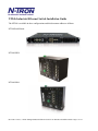
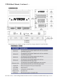
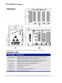
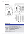


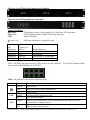

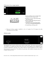
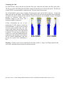

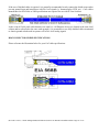
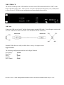
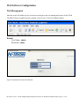


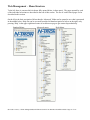

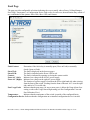
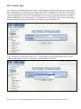
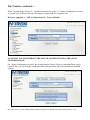
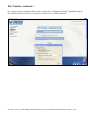
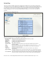
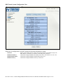
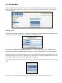

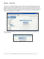
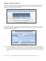

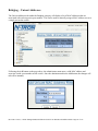
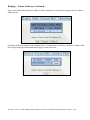
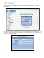

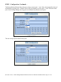
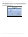
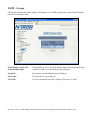
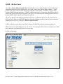
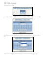
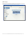
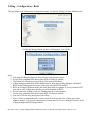
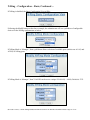
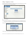
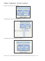
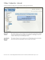

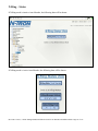
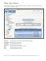
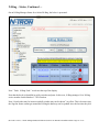

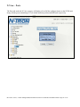
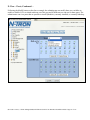
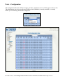
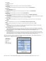
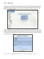
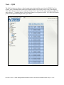
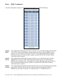
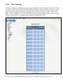
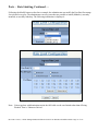
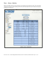
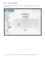
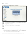
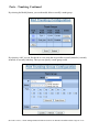
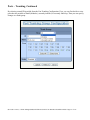
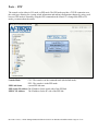
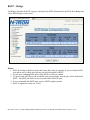
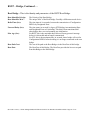

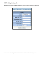

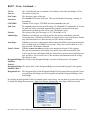
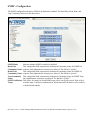
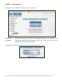
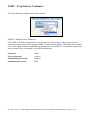
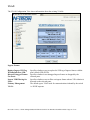
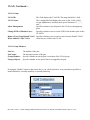
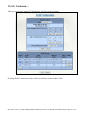

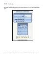
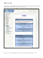

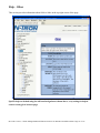

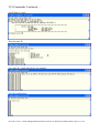
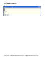


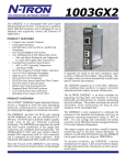


![sf-list [s]](http://vs1.manualzilla.com/store/data/005727021_1-5e70d84b679a2d9887789b982f459474-150x150.png)